Embed Size (px)
Citation preview

BDC05S-04 Page 1 of 74
New Jersey Department of Transportation
1035 Parkway Avenue, PO Box 600, Trenton, New Jersey 08625-0600
Baseline Document Change Announcement
High Performance Concrete, Composite Piles BDC05S-04 June 15, 2005 SUBJECT: Revision to Divisions 100, 500 and 900 of the 2001 Standard Specifications,
both English and Metric Units regarding High Performance Concrete (HPC) and Composite Piles.
Several sections of Divisions 100, 500 and 900 of the 2001 Standard specifications have been revised to include specifications for High Performance Concrete, Composite Piles, and other miscellaneous revisions. The following revisions have been incorporated in both the English unit Standard Input SI2001E1 and Metric unit Standard Input SI2001M1 as of June 15, 2005: The following revisions are incorporated in the English unit Standard Input SI2001E1:
SECTION 105 – CONTROL OF WORK 105.04 Working Drawings. THE FOLLOWING IS ADDED TO THE END OF THE SEVENTEENTH PARAGRAPH:
22. Precast Concrete Arch Structures
SECTION 109 – MEASUREMENT AND PAYMENT 109.01 Measurement of Quantities. THE 25TH TYPE 2 PAY ITEM IS CHANGED TO:
Type 2 Pay Items Charge per Unit of Measure
SAWCUT GROOVED DECK SURFACE $0.06 PER SQUARE FOOT
BDC05S-04 Page 2 of 74
SECTION 201 – CLEARING SITE 201.11 Method of Measurement. THE FOLLOWING IS ADDED:
Excavation or the use of any type of sheeting that is required for the removal of the structure, or when such sheeting is to remain for planned new construction that is at the same location of the removal, will not be measured. Payment shall be included in the bid price for “Clearing Site, _______”.
SECTION 501 – CONCRETE STRUCTURES 501.01 Description. THE FOLLOWING IS ADDED AFTER THE FIRST PARAGRAPH:
This work shall also consist of the construction of portland cement concrete deck slabs, parapets and sidewalks with the use of High Performance Concrete (HPC). Additionally, HPC shall be used for the protection of substructures that may be subjected to waterway abrasion. THE SECOND THROUGH SIX PARAGRAPHS ARE DELETED. 501.02 Materials. THE FOLLOWING IS ADDED TO THE FIRST PARAGRAPHS MATERIAL LIST
High Performance Concrete................................................................................................................ 914.02 THE FOLLOWING IS ADDED AFTER THE FIRST PARAGRAPH:
The epoxy resin system that is to be used for the filling of concrete cracks by pressure injection shall be a two component 100 percent solid moisture insensitive high-modulus high-strength epoxy resin adhesive. The following products, or approved equal, may be used:
1. Sikadur Hi-Mod LV, manufactured by Sika Corporation. 2. Duralcrete, as manufactured by Dural International Corporation. 3. Metaband HMLV, as manufactured by American Metaseal Company. 4. Thermal-Chem Injection Resin Product No. 2, as manufactured by Thermal-Chem, Inc. 5. Concressive 1380, as manufactured by Adhesive Engineering Co. of San Carlos, California.
THE FOLLOWING IS ADDED:
In the production of HPC, in order to achieve the desired resistance to chloride penetration, an appropriate pozzalonic or other cementitious material; such as, silica fume, fly ash or ground granulated blast furnace slag shall be provided in the mix design.
Silica fume shall not be used as a sole material to achieve the desired resistance to chlorides. When used, silica fume’s content shall be limited to a maximum of 5 percent of the total cement content and a proportion of fly ash or ground granulated blast furnace slag shall be included to obtain the resistance specified in 914.02 to chloride penetration. The fly ash and ground granulated blast furnace slag limitations specified in 914.02 may be increased in the fabrication of HPC.
The maximum water cement ratio shall be maintained at 0.40. In the fabrication of HPC, the cement content should not be increased for the purpose of achieving high early strength. THE FOURTH THROUGH SIX PARAGRAPHS ARE DELETED. 501.05 Working Drawings. THE SECOND, THIRD AND FOURTH ARAGRAPHS ARE DELETED. 501.07 Forms.
7. a. Design.

BDC05S-04 Page 3 of 74
THE SEVENTH PARAGRAPH IS CHANGED TO:
The spacing (pitch) of the ribs (flutes) shall match the spacing of the bottom main reinforcement steel, except on curved girder structures and in the areas of bridge decks with a flared rebar pattern. In these locations, the pitch of the flutes may be independent of the bottom main reinforcement spacing, and the forms may be dropped as necessary to achieve the minimum 1 inch concrete cover between the main reinforcement steel and the form. When the forms are dropped, additional dead load shall be accounted for in the design. Approval from the Engineer to drop the forms shall be obtained before construction of the deck begins.
b. Construction.
THE FOLLOWING IS ADDED AT THE END OF THE SECOND PARAGRAPH:
Joints between the forms should be lapped in the direction of concrete placement. 501.11 Limitations of Placing. THE SECOND SENTENCE OF THE FIRST PARAGRAPH IS CHANGED TO: In no case, during mixing and placement, shall the temperature of the concrete be less than 60 or more than 90 degrees F. 501.12 Placing Concrete.
5. Deck Slabs. THE FOLLOWING IS ADDED AFTER THE FIRST PARAGRAPH:
a. General Provisions. The following provisions shall be adhered to in all concrete deck slab construction.
THE 21 ST PARAGRAPH IS CHANGED TO:
When the concrete placing within any complete unit (i.e., for trusses, arches, continuous or cantilevered unit) is to be divided, the placing shall be made and finished in the numbered sequence shown, beginning with the lowest number. All sections having the same number shall be placed before sections of higher number. The sequence of placing for sections having the same number shall be optional. No deck section shall be placed until all previously placed concrete within the complete unit has cured for 72 hours. This requirement may be waived if the succeeding section(s) can be completed within four hours after the start of the initial placement of section(s) of any given unit for that day. A written request to waive this requirement shall be submitted to the Engineer for approval. This requirement may not be waived for deck slabs on prestressed concrete beams that are continuous for live load. The numbered sequence shown on the Plans shall be adhered to
THE FOLLOWING IS ADDED:
b. High Performance Concrete (HPC) for Deck Slabs, Sidewalks, Concrete Railings and substructure Protection. HPC is defined as concrete that meets special performance and uniformity requirements that cannot always be obtained by using conventional ingredients, normal mixing procedures and typical curing practices. The furnishing of HPC shall conform to the requirements of 914.02. (1) The Contractor is advised that curing of the HPC deck slab shall be performed in accordance
with the provisions of Subsection 501.17. Upon completion of the 7 day wet curing period, the HPC deck slab shall be further cured according to the provisions of Subsection 405.14, Subpart 1.
(2) The finishing machine equipment shall be set up so that the HPC is placed only 6 to 8 feet ahead of the machine.
15. Pumped Concrete.
THE FOLLOWING IS ADDED:

BDC05S-04 Page 4 of 74
As per the provisions of 914.04, fresh mixed concrete shall be sampled according to the requirements of AASHTO T 141. Samples shall be taken at the discharge of the concrete pump. If the Engineer believes that this is not a feasible, the pump shall be calibrated to calculate slump and air entrainment losses. These losses shall be deducted from the values as sampled from the concrete truck.
17. Reinforced Concrete Box Culvert, Precast.
THIS SUBPART IS DELETED
18. Slip-form Method of Parapet Construction. THIS SUBPART NUMBER IS CHANGED TO:
17. Slip-form Method of Parapet Construction.
19. Corrosion Inhibitor Admixture. THIS SUBPART NUMBER IS CHANGED TO:
18. Corrosion Inhibitor Admixture. PARAGRAPG C IS DELETED
20. Pressure Injection. THIS SUBPART NUMBER IS CHANGED TO:
19. Pressure Injection. THE FOLLOWING SUBPART IS ADDED:
20. Mass Concrete. Mass concrete is the placement of any large volume of cast in place concrete or precast concrete with dimensions large enough to require that measures be taken to cope with the generation of heat and attendant volume change, so as to minimize cracking.
A Mass Concrete member is defined as any concrete placement where each measured dimension of a
concrete component exceeds 3 feet and the ratio of its volume to surface area is greater than 1 foot. The surface area will include all of the cumulative area of all surfaces of the concrete component being considered including the full underside (bottom) surface of footings, caps, etc. Volume and surface area calculations shall be in units of feet. Therefore, the volume shall be measured in units of cubic feet and the area in units of square feet.
Mass concrete members will be as designated on the plans. Deck slab placements will not be considered
as mass concrete.
a. Thermal Curing Plan. At least 20 days prior to the Mass Concrete pour; the Contractor shall submit to the Engineer a Thermal Curing Plan Report. The Report shall address the following issues:
(1) An analysis of the anticipated thermal developments within the mass pour placements using
proposed materials and casting methods.
(2) A plan outlining specific measures to be taken to control the temperature differential within the limits stated below.
(3) The proposed monitoring system.
(4) Outline of corrective actions to maintain the temperature differential.
(5) Proposed methods of repairs or corrective actions if the mass concrete member is not
accepted.
b. Curing and Monitoring. The Contractor shall thermally cure the concrete so as to maintain a temperature differential between the internal (hottest – located as close as possible to the center of

BDC05S-04 Page 5 of 74
the pour but not less than 12 inches from the surface and external (coolest) temperature of the concrete to a 35 degrees F. maximum. In addition, the internal temperature of the concrete (measured at the hottest point located at the center of the pour) shall at no time exceed 160 degrees F.
The Contractor shall provide temperature-monitoring devices to record temperature
development between the interior and exterior of the element at points approved by the Engineer and shall monitor the mass pours to measure temperature differentials. Temperature monitoring shall continue until the interior temperature is within 35 degrees F. of the lowest ambient temperature or a maximum of two weeks. The Resident Engineer shall be provided with a copy of each set of readings as they are taken and a temperature chart for each mass pour element showing temperature readings vs. time.
If monitoring indicates that the proposed measures are not controlling the concrete
temperature differential within the 35 degrees F. specified, the Contractor shall implement corrective actions as presented in the Thermal Curing Plan to maintain the temperature differential.
c. Concrete Mix Requirement. In order to better control the heat of hydration of the mass concrete,
the concrete mix design shall contain a pozzolanic material; such as, fly ash, silica fume or ground granulated blast furnace slag.
d. Approval and Acceptance. Should any mass concrete placed under this specification prove
unsatisfactory, the Contractor will be required to make the necessary repairs or remove and replace the material at the Contractor’s expense.
The Engineer will be the sole judge in determining acceptance of the Mass Concrete member.
Corrective actions, as approved in the Thermal Curing Plan Report, shall be made to those areas directed by the Engineer before the Mass Concrete member will be considered for acceptance.
501.15 Deck Slab Surface Texture Finish. THE FIRST PARAGRAPH AND SUBPART 1 ARE CHANGED TO:
The surface of the deck slab shall be finished according to Subsection 405.13 except that Subpart G shall not apply. The time between strike-off and application of deck slab surface texture finish in any location shall not exceed one hour. All concrete bridge deck slabs shall be textured with a stiff, coarse broom and shall be saw cut groove finished as follows:
1. Broom Finish. Immediately after finishing has been completed, the surface shall be given a texture with an approved stiff, coarse broom.
The broom shall be operated in a longitudinal or transverse direction. Once begun, the direction of texturing shall not be changed. Transverse texturing shall be done from a work bridge.
The broom finish shall be applied so as to prevent ridges or gouges from forming in the concrete surface. The broom shall be weighted and the contact area changed as required to produce a uniform texture. The broom shall be cleaned periodically to remove all hardened concrete particles. Texture resulting from the broom shall stop within 1 foot of curbs.
3. Saw Cut Grooved Surface.
THE SECOND PARAGRAPH IS DELETED. 501.16 Concrete Deck Surface Requirements.
B. Control Testing. THIS SUBPART IS CHANGED
Deck slab surfaces shall be checked during placement to correct surface irregularities while the concrete is in workable condition.
Such control testing shall be performed as follows:

BDC05S-04 Page 6 of 74
1. After strike-off, the deck surface shall be checked with an aluminum straightedge having a minimum length of 10 feet, as provided by the contractor. The Resident Engineer shall determine the specific conduct of the control testing, including the number and location of Straightedge checks. Surface variations shall be corrected before the concrete sets. Major deviations shall be corrected by the finishing machine or other strike-off, while minor deviations may be corrected by a straightedge or float. The addition of water to the surface of the concrete to assist in finishing operations will not be permitted.
501.17 Curing and Protecting Concrete
A. Curing Concrete Under Normal Conditions. THIS SUBPART IS CHANGED TO:
Concrete decks, curbs, and tops of sidewalks for one-course deck slab construction shall be cured according to Subheading 4 of Subsection 405.14 with the exception that the minimum wet cure period shall not be less than seven calendar days. The burlap shall be kept continuously wet throughout this curing period. According to the provisions of Subheading 3 of Subsection 405.14, the wet burlap shall be covered with white polyethylene sheeting for the seven-day duration. The polyethylene sheeting shall be lapped at the joints and secured to the deck as tightly as possible. In two-course deck slab construction, the Contractor shall prepare the entire deck surface area according to Subheading 6 of Subpart C of Subsection 518.06 before placing the second course. The second course shall be cured according to Subsection 518.06 C.12.
The time between final finishing and application of the wet burlap shall not exceed 20 minutes in any
location within the placement area.
Other concrete structures and concrete surfaces to receive an epoxy coating, rubbed finish or to be covered with another material shall be cured according to Subheadings 2, 3, 4, and 5 of the sixth paragraph of Subsection 405.14.
501.25 Method of Measurement. THE 8TH PARAGRAPH IS DELETED. 501.26 Basis of Payment. THE 18TH PAY ITEM IS CHANGED TO:
Pay Item Pay Unit SAWCUT GROOVED DECK SURFACE SQUARE FOOT
THE FOLLOWING PAY ITEMS ARE ADDED:
CONCRETE IN SUPERSTRUCTURE, DECK SLABS HPC CUBIC YARD CONCRETE IN SUPERSTRUCTURE, SIDEWALKS HPC CUBIC YARD CONCRETE IN SUPERSTRUCTURE, PARAPETS HPC LINEAR FOOT CONCRETE IN SUBSTRUCTURES, HPC CUBIC YARD
THE 19TH PAY ITEM IS DELETED. THE FOLLOWING IS ADDED:
No separate payment will be made for work described under 501.12, Subpart 20. Mass Concrete. Such cost shall be included in the bid price for the applicable Pay Item.
In the construction of deck joint systems, no separate payment will be made for supplying and installation of steel armoring that is to be placed on the roadway side of the header. Such cost shall be included in the bid price for the Pay Item “Concrete in Substructures, Abutment Walls”.
Payment for the furnishing of the F–Shape and Texas Type HT barriers shall be made under the Item “Concrete in Superstructure, Parapets”. Steel railing that is to be provided with the Texas Type HT barrier shall be included in the Item.
The Pay Item “Concrete in Superstructure Deck Slabs, HPC” will include payment for use of HPC for sidewalks and concrete bridge railings.

BDC05S-04 Page 7 of 74
The pay item “Concrete in Substructures, HPC” will include payment for use of HPC for substructure member protection concrete.
SECTION 502 – PRESTRESSED CONCRETE STRUCTURES THE TITLE OF THIS SECTION IS CHANGED TO:
SECTION 502 – PRECAST/PRESTRESSSED CONCRETE STRUCTURES 502.01 Description. THE FOLLOWING IS ADDED:
This work shall also consist of manufacturing, furnishing, and erecting of precast reinforced concrete box culverts and precast concrete arch structures in accordance with these Specifications and in conformity with the lines, grades and dimensions shown on the Plans.
The use of precast concrete end sections, including headwalls and wingwalls, is permitted. However, precast end sections for precast concrete culverts shall not be used when the skew angle requires that the smallest side of the precast concrete culvert segment is less than 3 feet. In such cases, cast-in-place end sections shall be provided. Adequate provisions shall be made for cast-in-place appurtenances, such as end sections, headwalls, wingwalls, aprons, and cut-off walls. Such provisions shall include proper transition of the precast culvert unit section into the cast-in-place appurtenance section. If the sections do not align, both the cast in place appurtenance and precast culvert unit section shall be redesigned and properly detailed.
Unless otherwise stated, all provisions of Sections 501, 502, and 914 shall apply in the furnishing of precast concrete culverts and precast concrete arch structures.
Materials and methods of construction that are used in the furnishing of precast concrete culverts and precast concrete arch structures and that are not specifically covered on the Plans and in these Specifications shall conform to the AASHTO LRFD Bridge Design Specifications or to the AASHTO Standard Specifications for Highway Bridges, whichever is applicable. In lieu of the applicable AASHTO Specifications, the current ACI Manual of Concrete Practice and the current PCI Precast Prestressed Bridge Design Manual shall be adhered to. 502.02 Materials. THE FOLLOWING IS ADDED:
Concrete for precast concrete culverts and precast concrete arch structures, according to Section 914, shall be, as a minimum, Class P concrete. However, coarse aggregate for such concrete shall be washed gravel or broken stone of argillite, granite, gneiss, quartzite, or trap rock conforming to the requirements of Section 901, and shall also be graded as specified for size No. 57 or 67.
Reinforcement steel for precast concrete culverts and precast concrete arch structures shall be deformed billet steel bars or welded wire fabric. The deformed billet bars shall conform to AASHTO M 31, Grade 60. The welded wire fabric shall conform to ASTM A-497 or ASTM A-185. Longitudinal distribution reinforcement may consist of welded wire fabric or deformed billet steel bars. Welded wire fabric shall not be shipped in rolls but shall be shipped in mats.
Longitudinal ties used to tie the precast concrete culvert units together shall be ¾-inch diameter high-tensile strength steel bars conforming to AASHTO M 275 or ½-inch, Grade 270 polystrands conforming to AASHTO M 203. No splices will be allowed in the ½-inch diameter polystrands, if used. Bars shall be galvanized according to AASHTO M 111. End anchorages (nuts, washers, and anchor plates), to be used with high-tensile strength steel bars, shall be approved by the Engineer. End anchorages shall be compatible with the tie rod system and shall be galvanized according to AASHTO M 111. When corrosion protection of the longitudinal ties is specified, the ¾-inch diameter high-tensile strength steel bar shall be used. Anchorages and end fittings for the ½-inch diameter polystrands and the corrosion protection method for the end fittings shall be as indicated on the Plans. 502.04 Working Drawings. THE FOLLOWING IS ADDED:
Before fabrication of precast concrete culverts and precast concrete arch structures, the Contractor shall submit complete working drawings and erection plans according to Subsection 105.04.

BDC05S-04 Page 8 of 74
Working drawings for precast concrete culverts and precast concrete arch structures shall show plan, elevation, and sections as well as details for all appurtenances such as headwalls, cutoff walls, wingwalls, and aprons. In addition, working drawings shall show details of the neoprene gasket between the precast concrete culvert units as well as all threaded inserts, bar extensions, waterproofing, and end anchorage details for the longitudinal ties.
Erection details shall be complete in every detail including handling points, neoprene gasket details, the method for pulling the culvert boxes together, details of the joint seal between the precast arch units, joint seal details, section lengths and the method of installing the units. Additionally, the working drawings shall indicate the profiles and dimensions of all precast arch units, lifting loads of all components and steel reinforcement layout. 502.15 Storage, Transportation and Erection. THE FOLLOWING IS ADDED TO THE NINTH PARAGRAPH: Additionally, the requirements stated in Subsection 503.07 B. shall be followed for the erection process. THE NEW SUBSECTION IS ADDED: 502.16 Precast Concrete Structures.
The fabricator of precast concrete structures shall be certified by the PCI or the NPCA to the category of applicable work. The certification will be maintained during production of items for the Project. A copy of the current field audit report shall be submitted to the Department’s Bureau of Materials before the start of production. The fabricator shall provide an Engineer’s office according to Subsection 502.03, Subpart E.
1. Precast Concrete Box Culverts.
a. Design and Detail Requirements. Precast concrete units shall be designed with a minimum design compressive strength of f 'c= 5,000
pounds per square inch . The cover of concrete over the circumferential reinforcement shall be 1½ inches except on the top
slab where it shall be 2 inches. Reinforcement bars shall be tied at all intersections, except where the spacing is less than 12 inches in
each direction, in which case alternate intersections shall be tied. The wall thickness for the precast culvert shall be a minimum of 8 inches. The top and bottom slab
thickness shall be a minimum of 10 inches. A flexible, watertight neoprene gasket, conforming to ASTM D-1056 requirements, shall be provided
at the joint between the precast units. The gasket shall be continuous around the circumference of the joint and shall contain only one splice.
A positive means shall be provided to prevent water from entering the vertical joint between the last precast culvert section and any cast-in-place appurtenances such as wingwalls, cutoff walls, aprons, and cast-in-place culvert end sections.
Two rows of threaded inserts or bar extensions shall be provided in the last precast culvert section for the cast-in-place end section and the wingwall attachment. The same information shall be provided for the headwall attachment, if necessary.
When the earth fill over the precast culvert is less than 2 feet, the top mat of reinforcement in the roof slab shall be corrosion protected.
Lifting devices will be permitted in each precast unit for the purpose of handling and erection. If lifting hooks or lugs are used, they shall be galvanized according to AASHTO M 111. The precast units shall be tied together with a minimum of four longitudinal rods or strands to ensure an adequate seal and to provide continuity and concrete shear transfer between the precast units. For the purpose of tying units together, a 1½-inch diameter hole shall be preformed in each corner of each unit. If hand holes are used for the installation of the longitudinal ties, they shall be spaced appropriately.
Design calculations shall be submitted according to Subsection 105.04.
b. Fabrication Requirements Each precast concrete culvert unit shall be identified with a permanent marking. The precast concrete
culvert units shall be manufactured in steel forms. Curing of the precast units shall be by any one of the

BDC05S-04 Page 9 of 74
methods specified in Subsections 4.19 and 4.20 of the PCI Manual for Quality Control for Plants and Production of Precast Prestressed Concrete Products.
If steam curing is used, the PCI Manual is amended as follows. The application of steam within the enclosure shall be delayed for a period of five to six hours when the air temperature is less than 50 ºF and shall be delayed for a period of three hours when the air temperature is 50 ºF or higher. If retarders are used, the waiting period shall be from four to six hours regardless of the air temperature. The temperature in the enclosure shall be maintained between 90 and 150 ºF for a period of 12 hours.
Two representative concrete test cylinders per precast culvert unit, similarly cured, shall be tested after the curing period specified above. Should tests indicate that the precast units have not achieved a compressive strength of 4,000 pounds per square inch or greater, the precast units shall be cured further until the required strength is achieved.
To determine the acceptance or failure of the concrete, one compressive strength test from the two concrete cylinders that are taken from each concrete truck or from each batch of concrete that is produced shall be performed. The two test results shall be averaged together to obtain a single value representing the units. Concrete will be accepted if this averaged single value is equal to or greater than the class design strength as identified in Section 914.05, Table 914-3. Concrete will be accepted with a pay adjustment if the averaged single value is no less than 500 psi below the class design strength of the specified concrete class, (i.e. for Class P concrete, this range will be between 5,000 to 5,500 pounds per square inch). The pay adjustment will be according to Section 914. Concrete will be rejected if the averaged single value is greater than an amount that is 500 pounds per square inch less than the class design strength for the specified concrete class. The Engineer may use testing results obtained from concrete cores or nondestructive testing before requiring any corrective action or removal and replacement of the concrete. All costs for coring and testing shall be paid for by the Contractor.
Precast concrete culvert units shall remain in their steel forms for the duration of the steam or natural curing operation. Upon removal of the forms, the entire precast concrete culvert unit including exterior, interior, and all lap surfaces shall be given a Class 1 finish according to Subheading 1 of the fourth paragraph of Subsection 501.14.
Upon approval of the Class 1 finish, precast concrete culvert units shall be given one coat of an epoxy waterproofing seal coat on the exterior of the roof slab. This coating shall be applied in the precaster’s plant not earlier than 72 hours after fabrication, and after the concrete compressive strength has reached 5,000 pounds per square inch. The concrete surfaces of the precast units shall be dry before application of the epoxy waterproofing seal coat. The application of the epoxy seal coat shall be in conformance with the product manufacturer’s recommendation.
Precast concrete culvert units shall not be shipped until 72 hours after fabrication and after the concrete compressive strength has reached 5,000 pounds per square inch.
The precaster is ultimately responsible for providing a finished product which is acceptable to the Engineer.
c. Construction and Erection. A coarse aggregate layer shall be provided under the precast concrete box
culvert. The minimum depth of the coarse aggregate layer shall be 2 feet. It shall extend 12 inches on each side of the precast box culvert. The coarse aggregate layer shall be compacted according to Subsection 203.09.
Before backfilling, a 2-foot wide strip of filter fabric shall be placed over the top and side transverse joints. The filter fabric shall be according to Subsection 919.06.
If precast concrete culvert units are used in parallel for multicell installations, the parallel units shall be placed a maximum of 6 inches apart, and the 6-inch space between the units shall be filled with non-shrink grout. As an alternate, the 6-inch space may be filled and compacted with Zone 2 or crushed stone conforming to coarse aggregate size No. 57. If crushed stone is used, a 2 foot-8 inch wide strip of filter fabric shall be placed over the longitudinal joint.
One longitudinal tie rod or strand shall be placed in position through a 1½-inch diameter preformed hole located in each corner of the box units (a minimum total of four longitudinal ties) and stressed to a tension of 30,000 pounds each. After tensioning, the exposed end of the ties shall be removed so that no part of the ties or no part of the end fittings extend beyond a point 1 inch inside the anchorage pocket. All hardware associated with the end anchorage system shall be galvanized. The exposed parts of the end fittings shall be coated with two coats of bituminous paint. If hand holes are used for the installation

BDC05S-04 Page 10 of 74
of longitudinal ties, they shall be spaced appropriately. A tensile force versus elongation chart for the strand shall be furnished by the fabricator.
The tie rod bars shall be tensioned by torquing. Precautions shall be taken during the tensioning process to prevent any damage to the concrete under the outside bearing plates. The tensioning process shall be conducted so that the tension being applied may be measured at all times.
Hand hole pockets, longitudinal tie rod sleeves, and lifting lugs shall be grouted after the joints are sealed and the longitudinal ties are tensioned. The grout shall be non-shrink and nonmetallic and conform to Subsection 914.03. Any top slab hand hole pockets or lifting holes which are grouted in the field shall receive one coat of an epoxy waterproofing seal coat after the grout has properly cured.
2. Precast Concrete Arch Structures.
a. Design and Detail Requirements.
Precast concrete arch units shall be designed and conform to, as a minimum, Class P concrete strength requirements. The Design Compressive Strength value shall be indicated on the Plans.
Each precast concrete arch structure unit shall be identified with a permanent marking. The precast concrete arch structure units shall be manufactured in steel forms. Curing of the units shall be by any one of the methods specified in Subsection 3.4.3 of the PCI Manual for Quality Control for Plants and Production of Precast Prestressed Concrete Products.
If steam curing is used, the PCI Manual is amended as follows. The application of steam within the enclosure shall be delayed for a period of five to six hours when the air temperature is less than 50 °F and shall be delayed for a period of three hours when the air temperature is 50 °F or higher. If retarders are used, the waiting period shall be from four to six hours regardless of the air temperature. The temperature in the enclosure shall be maintained between 90 °F and 150 ºF for a period of 12 hours.
Two representative concrete test cylinders per precast arch unit, similarly cured, shall be tested after the curing period specified above. Should tests indicate that the precast units have not achieved a compressive strength of 4000 psi or greater, the precast units shall be cured further until the required strength is achieved.
To determine the acceptance or failure of the concrete, one compressive strength test from the two concrete cylinders that are taken from each concrete truck or from each batch of concrete that is produced shall be performed. The two test results shall be averaged together to obtain a single value representing the units.
Concrete will be accepted if this averaged single value is equal to or greater than the class design strength as identified in Section 914.05, Table 914-3. Concrete will be accepted with a pay adjustment if the averaged single value is no less than 500 psi below the class design strength of the specified concrete class, (i.e. for Class P concrete, this range will be between 5000 psi to 5500 psi). The pay adjustment will be in accordance with 914.02.
Concrete will be rejected if the averaged single value is lower than 500 psi below the class design strength. The Engineer may use testing results obtained from concrete cores or nondestructive testing before requiring any corrective action or removal and replacement of the concrete.
The Contractor shall pay for all costs for coring and testing. Precast concrete arch units shall remain in their steel forms for the duration of the steam or natural
curing operation. Upon removal of the forms, the entire precast concrete arch unit including exterior, interior, and all lap surfaces shall be given a Class 1 finish in accordance with Subheading 1 of the fourth paragraph of 501.14.
Precast concrete arch units shall not be shipped until 72 hours after fabrication and after the concrete compressive strength has reached the design compressive strength as indicated on the Plans.
The joint between the arch units, the end unit and headwall and, if applicable, between the end unit and precast headwall shall be sealed in accordance with the Manufacturer’s specifications.
When the earth cover over the precast concrete arch unit is less than 24 inches, corrosion protected reinforcement shall be provided in the outside/top mat of reinforcement.
Design calculations shall be submitted in accordance with 105.04 and shall be signed and sealed by a Professional Engineer licensed in the State of New Jersey.
b. Fabrication Requirements. The cover of concrete over the reinforcing steel shall be a minimum of 2
inches on the outside face of the arch unit, and 1.5 inches on the inside face of the arch unit.

BDC05S-04 Page 11 of 74
Other permissible variations criteria shall conform to the requirements of AASHTO M 259. Special care must be taken when casting bearing surfaces to ensure that the units will join properly
when installed.
c. Construction and Erection. Precast Concrete Arch Structures shall be installed on cast-in-place concrete footings in accordance with the Manufacturer’s specifications. Footing concrete shall conform to Class B concrete requirements. The footings shall be constructed in accordance with the Working Drawings and to the elevations detailed on the plans. To assure against differential settlement of the arch units, the foundations for the arch units and other appurtenances shall be connected by reinforcement or suitable mechanical connections to form one monolithic body. The following provisions shall also be adhered to:
The Contractor shall provide to the Engineer written guidelines, be they in a product Manual or other type publication, that provides guidance on the erection and installation of their precast arch structure system.
The Contractor shall provide a crane that is capable of properly lifting the precast units. The Manufacturer shall be consulted to verify the ability of the selected crane.
The precast arch units shall be stored per the Manufacturer’s requirements. To prevent cracking of the units, for the storage duration, the precast arch units shall be supported by timber members.
A keyway, conforming to the Manufacturer’s specifications, shall be formed in the top surface of the footing. The footings shall be given a smooth float finish and shall reach a compressive strength of 3000 psi before placement of the arch sections.
The completed footing surface shall be constructed in accordance with grades shown on the plans. When tested with a 36 inch straight edge the surfaces shall not vary more than ¼ inch in 10 feet.
The arch units shall be placed as shown on the Working Drawings and as directed by the Manufacturer’s representative.
The footing keyway shall be filled with cement grout. Additionally, precast unit lifting points may be filled with cement grout or filled in accordance with Manufacturer’s specifications.
Provision of Backfill Material shall consist of placement of select granular borrow excavation that conforms to porous fill, designated I-9 and is in accordance with Section 203.
No backfill material shall be placed against any precast arch unit until its erection has been approved by the Engineer.
Mechanical tampers or approved compacting equipment shall be used to compact backfill and embankment immediately adjacent to each side of the arch units and over the top of the arch units until they are covered to a minimum depth of 12 inches. The backfill within 4 feet of each side of the arch unit shall be placed in lifts of 8 inches or less (loose depth). Heavy compaction equipment shall not be operated in this area or over the culvert until it is covered to a depth of 12 inches.
Heavy earth moving equipment (weighing in excess of 12 Tons or having track pressures of 8 psi or greater) shall require 2 feet of earth cover unless the design cover is less than 2 feet. In no case shall equipment operating in excess of the design load be permitted over the arch unit.
As a precaution against introducing unbalanced stresses in the arch structure and wingwalls, when placing backfill, at no time shall the difference between the heights on opposite sides of the arch structure exceed 2 feet.
The butt joint made by two adjoining arch units shall be sealed and covered in accordance with the Manufacturer’s specifications. The surface shall be free of dirt before the sealing operations begin. The joint shall be covered continuously from the bottom of one arch unit section leg across the top of the arch and to the opposite arch unit section leg. Any laps that result in the joint wrap shall be a minimum of 6 inches long with the overlap running downhill.
In addition to the joints between the units, the joint between the end unit and the headwall also shall be sealed in accordance with the Manufacturer’s specifications. If using precast wingwalls, the joint between the end arch unit and the wingwall shall also be accordingly sealed.
502.16 Method of Measurement. THE SUBSECTION NUMBER IS CHANGED: 502.17 Method of Measurement. 502.17 Method of Measurement.

BDC05S-04 Page 12 of 74
THE FOLLOWING IS ADDED:
Precast concrete box culverts and precast concrete arch structures will be measured by the linear foot along their centerline. 502.17 Basis of Payment. THE SUBSECTION NUMBER IS CHANGED: 502.18 Basis of Payment. 502.18 Basis of Payment. THE FOLLOWING PAY ITEMS ARE ADDED:
Pay Item Pay Unit
REINFORCED CONCRETE BOX CULVERT, PRECAST LINEAR FOOT PRECAST CONCRETE ARCH STRUCTURE LINEAR FOOT
THE FOLLOWING IS ADDED TO THE LAST PARAGRAPH:
Payment for the use of plain elastomeric bearing pads shall be included in the price that is bid for the prestressed concrete beam type that is to be used in the project. Payment for the use of other type bearing assemblies shall be according to the provisions of 503.18.
SECTION 503 – STEEL STRUCTURES 503.01 Description. THE FIRST PARAGRAPH IS CHANGED TO:
This work shall consist of the furnishing, fabrication, erection and painting of bridges, structures, furnishing of Structural Bearings and Reinforced Elastomeric Bearings and associated elements that include use of structural steel and miscellaneous metals. 503.02 Materials.
C. 1. Steel. THE FIRST SENTENCE IS CHANGED TO:
Steel that is to be used in the bearing assemblies shall conform to AASHTO M 270, Grades 36 or 50, except for steel that is used for guide bars and shear restriction pins and sleeves.
D. 1. b. (7)
THE 2ND SENTENCE IS DELETED.
E. 1. Elastomer Material. THE LAST SENTENCE IN THE FIRST PARAGRAPH IS DELETED.
E. 3. Bond Strength. THIS SUBPART IS CHANGE TO:
The vulcanized bond between fabric and reinforcement shall have a minimum peel strength of 30 lbs/inch. Steel laminated bearings shall develop a minimum peel strength of 40 lbs/inch. Peel strength tests shall be performed by ASTM D 429 Method B.
503.03 Inspection and Testing. THE SUBPART 1 IS CHANGED TO:
1. Steel bridge bearings and HLMR bearing assemblies are considered to be main load carrying members.
BDC05S-04 Page 13 of 74
THE SUBPART 2 a IS CHANGED TO:
2. a. Simple Steel Bridge Structures (SBr): Includes highway sign support structures, parts for bridges (such as cross frames), unspliced rolled steel bridges, steel bridge bearings and HLMR bearing assemblies.
THE SUBPART 4 c IS CHANGED TO:
4. c. Fracture Control Plan. Steel bridge members or member components designated as Fracture Critical Members (FCM’s) shall conform to the provisions of the most current edition of the AASHTO/AWS D1.5 Bridge Welding Code, Section 12 “AASHTO/AWS Fracture Control Plan (FCP) for Non-Redundant Members”.
503.07 Shipping, Handling and Erection.
B. Erection. THE FOLLOWING IS ADDED TO THE FIRST LISTED ITEM 2.:
The written plan shall be signed by a Professional Engineer licensed in the State of New Jersey. The Contractor’s Professional Engineer and the State’s Design Engineer shall attend the meeting.
THE FOLLOWING IS ADDED TO THE FIRST LIST:
4. The Contractor’s Professional Engineer shall inspect each phase of girder installation prior to permitting vehicular or pedestrian traffic on or below the bridge.
503.08 Setting Shoes and Bearings.
D. Structural Bearings. THE FIRST SENTENCE IS CHANGED TO:
This work shall consist of furnishing and installing structural bearing assemblies that are one or more of the following types: High Load Multi-Rotational (HLMR) bearings as defined in 503.02 or Seismic Isolation Bearings. As per the requirements of 105.04, Working Drawings, for the complete design of such structural bearing assemblies, shall be submitted. The designs shall conform to the provisions of the AASHTO LRFD Bridge Design Specifications and/or the AASHTO LRFD Bridge Construction Specifications and these Specifications.
503.15 Cleaning and Painting of Structural Steel.
A. 4. f THE FOLLOWING IS ADDED AFTER THE FIRST SENTENCE:
Surfaces of steel that will be embedded in concrete shall be given a prime coat of paint only.
F. 3. b SUBPART B IS CHANGE TO:
With the exception of steel designated to be galvanized, all structural steel for a distance away from the ends of the girders of 1.5 times the depth of the girder or a maximum of 6 feet shall be cleaned and painted.
503.17 Method of Measurement. THE FOLLOWING IS ADDED:
Reinforced Elastomeric Bearing assemblies shall be measured on a Unit basis. 503.18 Basis of Payment. THE FOLLOWING PAY ITEM IS DELETED:

BDC05S-04 Page 14 of 74
Pay Item Pay Unit
STEEL BEARINGS FOR PRESTRESSED CONCRETE BEAMS LUMP SUM
THE FOLLOWING PAY ITEM IS ADDED:
Pay Item Pay Unit
REINFORCED ELASTOMERIC BEARING ASSEMBLY UNIT
SECTION 505 – LOAD BEARING PILES 505.03 Equipment.
B. Impact Pile Drivers. SUBPART 3. IS CHANGED TO:
3. For steam or air hammers, the weight of the ram shall be no less than 1/3 the weight of the pile. For diesel hammers, the weight of the ram shall be no less than ¼ the weight of the pile.
E. Leads and Followers.
THE FOLLOWING IS ADDED AFTER THE SECOND SENTENCE:
Leads may be either of the fixed or swinging type. Fixed leads, when used, shall be held in position by guys or braces to ensure support to the pile during driving. Swinging leads, when used, shall be fitted with a pile gate at the bottom of the leads and, in the case of battered piles, a horizontal brace may be required. Swinging leads shall be adequately embedded in the ground or the pile constrained in a structural frame such as a template to maintain alignment.
G. Hammer Cushion (Cap Block) and Pile Cushion.
1. Hammer Cushion. THE SECOND AND THIRD SENTENCES ARE CHANGE TO:
Hammer cushions (cap block) shall be made of manufactured materials according to the hammer manufacturers guidelines. Wood, rope, wire rope, hose, tires and asbestos cushions are specifically disallowed and shall not be used.
505.04 Preparation for Driving. THE FOLLOWING IS ADDED:
4. Installation Sequence. The order of placing individual piles in pile groups shall be either starting from the center of the group and proceeding outwards in both directions or, starting at an outside row and proceeding progressively across the group.
505.06 Methods of Driving.
1. Accuracy of Driving. THE FIRST SENTENCE IS CHANGED TO:
Foundation and fender piles shall be driven with a variation of not more than ¼ inch per foot from the vertical or from the batter. Foundation piles shall not be out of the required position by more than 6 inches after driving, or ¼ of their diameter, whichever is greater.
505.07 Determination of Bearing Values.
4. Dynamic Pile Load Tests. THE THIRD SENTENCE OF THE FIFTH PARAGRAPH IS CHANGED TO:

BDC05S-04 Page 15 of 74
The restrike should be terminated when the ultimate capacity of the pile is reached or the penetration reaches 6 inches or the total number of hammer blows reaches 50, whichever occurs first.
505.11 Manufacture of Precast Concrete Piles and Precast Concrete Pile Caps. THE THIRD PARAGRAPH IS CHANGED TO:
Concrete piles for use in seawater and sulfate soils shall be cured for not less than 30 days before being used. 505.12 Extensions and Splices.
B. Precast and Prestressed Concrete Piles. THE FIRST SENTENCE OF THE SECOND PARAGRAPH IS CHANGE TO:
After the driving is completed, the concrete at the end of the pile shall be cut away leaving the reinforcing steel exposed for a length of 40 diameters.
505.13 Cut-Offs and Cappings. THE SECOND PARAGRAPH IS DELETED. THE THIRD PARAGRAPH IS CHANGED TO:
As shown on the Plans, all piles shall be anchored to the structure. 505.15 Method of Measurement. THE 10TH PARAGRAPH IS CHANGED TO:
Splices for all type piles will be measured per each individual splice. However, splices within the pile length ordered by the Engineer will not be measured unless the ordered length is in excess of 80 feet.
SECTION 506 – BULKHEADS, FENDER SYSTEMS, AND DOLPHINS 506.01 Description. THE FOLLOWING IS ADDED:
This work shall also consist of designing, furnishing and installation of Fiberglass-Concrete Composite Piles (FCCP) and Fiberglass Reinforced Plastic Piles (FRPP) that may be used for the construction of fender systems and dolphins. All equipment, materials and labor that are required to install these type piles, as shown on the plans, shall be included.
This work shall also consist of designing, furnishing and installing Fiberglass Reinforced Plastic Lumber (FRPL) wales for fender systems and smaller dimensional FRPL for fender system platforms as shown on the plans and specified herein. 506.02 Materials. THE FOLLOWING IS ADDED TO THE LIST OF MATERIAL REFERENCES:
Fiber Reinforced Plastic Lumber………………………………………………..………….…..921 Fiberglass Reinforced Plastic Piles……………………………………………………………..922 Fiberglass-Concrete Composite Piles…………………………………………………………..923
THE FOLLOWING IS ADDED:
The material conformance criteria of Section 921 shall be followed for supplying FRPL, of Section 922 for supplying FRPP and of Section 923 for supplying FCCP.
BDC05S-04 Page 16 of 74
THE NEW SUBSECTION IS ADDED: 506.06 Fiberglass-Concrete Composite Piles / Fiberglass Reinforced Plastic Piles / Fiberglass Reinforced Plastic
Lumber.
A. Fiberglass-Concrete Composite Piles (FCCP). The following criteria shall be followed in furnishing (FCCP). 1. Working Drawings. According to the requirements of 105.04, Working Drawings for FCCP shall be
submitted. The submission shall include test results and calculations to establish the flexural strength requirements stated herein and shall also include the following criteria:
a. The outside diameter of the FCCP and wall thickness of the composite reinforcement tube. b. The location of any embedded or attached lifting devices and use of pick up or support points. c. The location of the roughened surface where skin friction is needed between the pile and the
soil. d. The location of detailing of any splices, shoes and top of pile connections that may be
required. 2. Additional Submittals. The following documentation and details shall be submitted to the Engineer for
approval at least thirty (30) days prior to the scheduled FCCP installation. a. Documentation that indicates the fiberglass tubing physical properties and the diameter and
wall thickness of the tubes. b. The method of placing concrete in the fiberglass tubes. c. Catalog cuts, illustrations, schedules, diagrams, performance charts, instructions, brochures or
lab reports that illustrate the size, physical appearance and other characteristics of FCCP that indicate conformity to the requirements of the Plans and the requirements specified in Section 923.
d. Lab reports from an independent testing facility shall include calculations that confirm that the FCCP meets the ultimate strength requirements specified in Section 923. A minimum of three (3) flexural tests shall be required. The average of the three tests shall exceed the specified ultimate flexural strength.
e. Placement method of the concrete for the fiberglass tubes. The concrete shall be placed in one continuous bottom to top operation in a manner that prevents voids from forming.
3. Storage and Handling. FCCP shall not be installed until 30 days after concrete has been placed in the tubes. FCCP shall be stored and handled to avoid damage to all components including fiberglass tubes, protective coatings and concrete. During storage, the piles shall be placed on minimum 6 inch wide timber cribbing arranged to give even support and to maintain straightness within the tolerance specified herein.
4. Lifting Piles. Only fabric slings may be used to lift the piles. Chain or cable in direct contact with the piles may not be used.
5. Splices. Full length piles where practicable shall be used. Where splices are unavoidable their number and locations will be subject to written approval by the Engineer. Splicing details shall be submitted to the Engineer for approval.
6. Shoes. Steel shoes for FCCP, when required, shall be provided. Install shoes in conformance with details submitted to and approved by the Engineer.
7. Equipment for Driving FCCP. a. Equipment for driving FCCP shall conform to the requirements of 505.03. b. As per the requirements of 505.03 G., an approved hammer cushion block to transfer pile
hammer energy to the FCCP shall be used. Each hammer shall be equipped with a helmet/drive head to fit the diameter of the FCCP to be driven.
c. As per the requirements of 505.03 G., an approved pile cushion block to prevent damage to the FCCP shall be used. At a minimum frequency, the pile cushion block shall be inspected after each FCCP is driven and replaced as needed.
8. Allowable. Variation in Pile Alignment. FCCP shall be installed truly vertical or accurately battered as indicated on the Plans. The top of any FCCP driven its full length into the ground shall not vary from the plan location by more than 2 inches.
9. Defective Composite Piles. The provisions of 505.08, in addition to the following, shall apply for determining FCCP defective characteristics. The following will be causes for rejection of a FCCP:

BDC05S-04 Page 17 of 74
a. Incorrect pile location or batter. b. Pile damage from any cause prior to driving. c. Insufficient concrete strength, based on testing of cylinders. d. FCCP broken by reason of internal defects (even if placed in the leads), or improper driving.
10. Cutting Off Piles. Tops of FCCP shall be cut off at the elevation indicated on the Plans, or as established by the Engineer. The FCCP shall be cut to a true plane, in accordance with the detail shown on the Plans. All cut off lengths will become the property of the Contractor.
B. Fibergalss Reinforced Plastic Lumber (FRPL). The following criteria shall be adhered to in furnishing
FRPL for the project: 1. Submission Requirements. The Contractor shall submit the following information to the Resident for
approval at least thirty (30) days before installation of FRPL. a. Copies of the FRPL manufacturer’s standards and most recent brochure for the product
covered by these Specifications. b. According to the requirements of Subsection 106.04, the Contractor shall submit a written
certification from the FRPL manufacturer that their product satisfies the requirements of Section 921 and has been in service for a minimum of three (3) years on other bridge protection applications in the United States. This written certification shall include project owner information, project names, locations, contacts and phone numbers.
c. Copies of independent lab test reports and performance test data that confirm that the FRPL meets the Plastic material properties and the structural property requirements specified in Section 921.
2. Shipping, Storage, Handling. During storage FRPL materials shall be protected at all times against exposure to extreme heat or impact. FRPL shall be shipped in a manner that will minimize scratching or damage to the outer surfaces. FRPL shall be stacked on dunnage above ground so that it may be easily inspected and stored in a manner that will avoid damage. FRPL shall be handled with nylon slings. Sharp instruments shall not be used in handling the product. FRPL damaged in shipping or handling will be rejected.
3. Installation. FRPL shall be cut, beveled, drilled, countersunk, and otherwise fabricated in accordance with the manufacturer’s recommendations. Set all material accurately to required levels and lines, with members plumb and true and accurately cut and fitted. Securely attach all FRPL to substrate by anchoring and fastening as shown on plans.
C. Fiberglass Reinforced Plastic Piles (FRPP). The following criteria shall be adhered to in furnishing FRPP
piles: 1. Working Drawings. According to the requirements of Subsection 105.04, FRPP submissions shall
consist of working drawings. The submission shall include calculations to establish the FRPP structural properties found in Tables 3-A and 3-B.
2. Additional Submittals. Submit the following documentation and details to the Engineer for approval at least thirty (30) days prior to driving the piles.
a. Copies of FRPP manufacturer’s standards and most recent product brochure for the product covered by these specifications.
b. Written certification from the FRPP manufacturer that their product meets the requirements of Section 922 and that the product has been in service for a minimum of three (3) years on at least 5 bridge protection applications in the United States. The certification shall include project owner information, project names, locations, contacts and phone numbers.
c. Independent test lab report confirming that FRPP meets the Plastic Material Properties and structural properties specified in Section 922.
d. Manufacturer’s field guide with recommendations on handling, storage, cutting, drilling and driving. Driving recommendations shall include recommended driving energies.
3. Splices. Splices shall not be permitted except where overhead restrictions in the driving area require splices to be used. Splicing details shall be submitted to the Engineer for approval.
4. Pile Points. Steel pile points shall be provided by the manufacturer and attached prior to shipment. 5. Allowable Variation in Pile Alignment. Install FRPP truly vertical or accurately battered as indicated
on the Contract Plans. The top of any pile driven its full length into the ground shall not vary from the plan location by more than 2 inches.

BDC05S-04 Page 18 of 74
6. Defective FRPP. The provisions of Subsection 505.08, in addition to the following, shall apply for determining FRPP defective characteristics:
a. Incorrect pile location or batter. b. Pile damage from any cause prior to driving. c. Pile broken by reason of internal defects (even if placed in the leads0, or improper driving.
7. Cutting Off Piles. Cut off the tops of FRPP at the elevation indicated on the Contract Plans, or as established by the Engineer. Cut the piles to a true plane, in accordance with the detail shown on the Contract Plans. All cut off lengths become the property of the Contractor.
8. Wrapping. Wrapping for the FRPP that are to be placed in clusters shall be ½” diameter cable (5/8” OD covering) polypropylene impregnated wire rope.
To verify suppliers of Composite Piles/Fiber Reinforced Plastic Piles/Composite Lumber that may be used, the
Contractor is advised to study the “Bureau of Material’s Approved List” on the following NJDOT website: http://www.state.nj.us/transportation/eng/technology/materials
506.06 Method of Measurement. THE SUBSECTION NUMBER IS CHANGED: 506.07 Method of Measurement. 506.07 Method of Measurement. THE FOLLOWING IS ADDED:
FRPP and FCCP will be measured in linear feet of pile that is placed in accordance with the plans.
FRPL will be measured in cubic feet computed on the basis of actual volumes and the shortest commercially available lengths which may be used and that is placed in accordance with the Plans. 506.07 Basis of Payment. THE SUBSECTION NUMBER IS CHANGED: 506.08 Basis of Payment. 506.08 Basis of Payment. THE FOLLOWING IS ADDED:
Pay Item Pay Unit
FIBERGLASS-CONCRETE COMPOSITE PILE (FCCP), ___ INCH DIAMETER LINEAR FOOT FIBERGLASS REINFORCED PLASTIC PILE (FRPP), ___INCH DIAMETER LINEAR FOOT FIBERGLASS REINFORCED PLASTIC LUMBER (FRPL) CUBIC FOOT
Wrapping is to be paid for under the item FIBERGLASS-CONCRETE COMPOSITE PILE (FCCP), ___ INCH
DIAMETER or FIBERGLASS REINFORCED PLASTIC PILE (FRPP), ___INCH DIAMETER No additional payment will be made for re-driving of FCCP or FRPP that are forced up by any cause. Included in
the Payment will be all costs for all material, labor, equipment, and other necessary items required for completing the work including storage costs, disposal of unused piles, repair to damaged piles, and transportation costs. Parts of pile cut off will not be included for payment.
Payment for FRPL shall include all material, labor, equipment, fasteners, and other necessary items required for completing the work including storage costs, disposal of unused materials, and transportation costs.
Also, no separate payment will be made for grout, plates, bolts, screws or other hardware that is needed for attaching the wales to the dolphins or for assembly and or installation of a platform. All costs hereof is to be included in the item FIBERGLASS REINFORCED PLASTIC LUMBER.
SECTION 509 – SIGN SUPPORT STRUCTURES 509.02 Materials. THE SEVENTH PARAGRAPH IS CHANGED TO:
BDC05S-04 Page 19 of 74
Caps for the ends of chords and tops of posts shall be steel conforming to AASHTO M 270 Grade 36 and shall be
hot dip galvanized according to ASTM A 123.
SECTION 513 – SHEETING, TEMPORARY AND LEFT IN PLACE 513.05 Method of Measurement. THE FIRST PARAGRAPH IS REMOVED AND THE FOLLOWING IS ADDED:
Temporary sheeting will be measured by the square foot basis. The area measured will be the product of the average height and the length of sheeting that is driven. The average height will be determined by extending a line from the bottom of excavation to a vertical plane of the top of sheeting.
SECTION 515 – GRANITE MASONRY 515.07 Pointing. THE FIRST SENTENCE OF THE SECOND PARAGRAPH IS CHANGED TO:
Pointing shall be done with epoxy mortar.
SECTION 518 – BRIDGE DECK REHABILITATION 518.02 Materials.
A. Repair of Concrete Deck. THE SECOND “OTHER MATERIALS” REFERENCE IS CHANGED TO:
Epoxy Bonding Coat ……………………………………………………………………………912.06 THE FIRST SENTENCE OF THE SECOND PARAGRAPH IS CHANGED TO:
To verify the approved product listing of quick-setting patching materials that may be used, the Contractor is advised to study the “Bureau of Material’s Approved List” on the following NJDOT website: http://www.state.nj.us/transportation/eng/technology/materials
B. Membrane Waterproofing.
THE FIRST SENTENCE OF THE FIRST PARAGRAPH IS CHANGED TO:
To verify approved membrane waterproofing products, the Contractor is advised to study the “Bureau of Material’s Approved List” on the following NJDOT website: http://www.state.nj.us/transportation/eng/technology/materials
C. Concrete Deck Overlay Protective System.
THE SECOND SENTENCE OF SUBPART 6 IS CHANGED TO:
To verify approved listing of Concrete Deck Overlay Protective Systems that may be used, the Contractor is advised to study the “Bureau of Material’s Approved List” on the following NJDOT website: http://www.state.nj.us/transportation/eng/technology/materials
518.06 Concrete Deck Overlay Protective System.
C. Furnishing and Installation. 13. Saw Cut Grooving.
THE FIRST SENTENCE IS CHANGED TO:
BDC05S-04 Page 20 of 74
After the completion of the curing time specified in C.12. the overlay shall be sawcut grooved according to Subsection 501.15, Item 3., provided that the concrete has attained a strength of at least 4000 psi as determined from cylinders that are cast during the placement.
SECTION 519 – PREFABRICATED MODULAR WALLS 519.01 Description. THE SECOND SENTENCE OF THE SECOND PARAGRAPH IS CHANGED TO:
To verify the approved listing of Prefabricated Modular Wall systems that may be used, the Contractor is advised to study the “Bureau of Material’s Approved List” on the following NJDOT website: http://www.state.nj.us/transportation/eng/technology/materials
519.02 Materials.
2. Joint Filler Material. THE SECOND SENTENCE IS CHANGED TO:
Filler for front face horizontal joints between units shall be closed-cell polyethylene foam backer rod conforming to AASHTO M 153, Type 1, fiber expansion joint material and shall be in conformance with 908.01.
SECTION 520 – MECHANICALLY STABILIZED EARTH (MSE) WALLS 520.01 Description. THE SECOND SENTENCE OF THE SEVENTH PARAGRAPH IS CHANGED TO:
To verify approved listing of MSE Wall systems that may be used, the Contractor is advised to study the “Bureau of Material’s Approved List” on the following NJDOT website: http://www.state.nj.us/transportation/eng/technology/materials 520.02 Materials.
6. Backfill Material. a. Select Granular Borrow Excavation Material.
THE FOURTH ITEM UNDER SIEVE SIZE IS CHANGED TO:
Sieve Size ...................................................................................................Percent Passing No. 50......................................................................................................................... ...0-20
THE THIRD PARAGRAPH IS CHANGED TO:
Select granular backfill shall meet the following recommended electrochemical limit requirements: THE FIRST ITEM IN FOURTH PARAGRAPH IS CHANGED TO:
Property Standard Test Procedure Resistivity, ohm-cm Greater than 3,000 ASTM G57
THE SIXTH PARAGRAPH IS CHANGED TO:
The frequency of sampling of select granular backfill necessary to ensure electrochemical limits shall be performed at least once for every 6000 cubic yards of material that is placed. A minimum of one sample per structure shall be taken. Whenever the appearance or behavior of the material changes and as directed, additional samples shall be taken.
THE SEVENTH PARAGRAPH IS CHANGED TO:

BDC05S-04 Page 21 of 74
The materials shall be substantially free of shale or other soft, poor durability particles. The
material shall have a sodium sulfate soundless loss of less than 15 percent after five cycles determined according to AASHTO T 104.
THE LAST PARAGRAPH IS CHANGED TO:
The Contractor shall determine, by means of proper sampling and laboratory tests that the Select Granular Material from proposed sources conform to the requirements of the Specifications. A copy of all test results performed by the Contractor shall be furnished to the Engineer prior to delivery of the material.
SECTION 521 – ALTERNATE RETAINING WALL DESIGNS 521.01 Description. THE FOLLOWING IS ADDED TO THE THIRD PARAGRAPH:
Also, as required, provision for furnishing cofferdam work shall be included.
SECTION 522 – NOISE BARRIERS 522.07 Foundations. THE EIGHTH PARAGRAPH IS CHANGED TO:
Permanent metal casings shall consist of zinc-coated steel.
SECTION 612 – BEAM GUIDE RAIL 612.08 Beam Guide Rail on Bridges. THE FOURTH PARAGRAPH IS DELETED.
SECTION 902 – BEAM GUIDE RAIL 902.02 Posts and Spacers. THE ENTIRE SUBSECTION TEXT IS CHANGED TO:
Suppliers for obtaining recycled/synthetic routed spacers will be identified in the Standard Input. According to the provisions of 105.04, the Working Drawing submission shall provide evidence that the spacers that are to be used do satisfy the above criteria. Steel spacers shall conform to AASHTO M 270 Grade 36 and shall be galvanized according to AASHTO M 111. Steel pipe spacers shall be schedule 40 galvanized pipe.
Wood timber spacers and posts shall conform to Subsection 918.01.
Steel posts shall be structural steel that conforms to AASHTO M 270 Grade 36 and shall be galvanized according to AASHTO M 111.
To verify suppliers for obtaining recycled/synthetic routed spacers (Polymer & Composite Blockouts), the Contractor is advised to study the “Bureau of Material’s Approved List” on the following NJDOT website:
http://www.state.nj.us/transportation/eng/technology/materials
BDC05S-04 Page 22 of 74
SECTION 908 - JOINT MATERIALS 908.03 Preformed Elastomeric Joint Sealer (Compression Type)
A. Requirements. THE SECOND SENTENCE IS CHANGED TO:
The material shall conform to the physical properties specified in Table 1 of ASTM D 3542 and as modified herein. The Compression-Deflection properties specified in Table 1 of ASTM 3542 shall be replaced with NJDOT Test Method J-2 as provided within these Specifications. The requirement for Pressure Deflection shall be 3.5 psi.
THE FIRST SENTENCE OF THE FIFTH PARAGRAPH IS CHANGED TO:
The width to height ratio of the compression sealer shall never be less than 90%. 908.05 Strip Seal Expansion Dam.
B. Glandular Type Strip Seal. 1. Scope.
THE FIRST SENTENCE IS CHANGED TO:
This specification covers the material requirements for glandular type strip seal deck joint systems consisting of an extruded neoprene rubber gland seal mechanically locked in the cavities of two parallel steel rail sections.
3. Metal Components and Adhesive.
THE FIRST AND SECOND SENTENCES ARE CHANGED TO:
Steel rail sections shall conform to AASHTO M 270 Grade 36 or 50. Steel for plates, shapes and other structural steel used in the deck joint system shall conform to AASHTO M 270 Grade 36 or 50.
SECTION 912 – PAINTS, COATINGS AND MARKINGS 912.13 Inorganic Zinc Coating System. THE FOLLOWING IS ADDED:
A complete coating system of an inorganic zinc rich primer, a high build epoxy intermediate coat and a urethane finish coat shall be selected from one of the approved coating systems listed on the following website:
http://www.state.nj.us/transportation/eng/technology/materials
All products for the complete system, including thinners and solvents, shall be from the same manufacturer and shall be from the Qualified Paint List.
Drying time between coats shall be per the manufacturer’s recommendations. The following information shall be submitted for the system selected at least one month before painting is
anticipated: 1. A 1-gallon sample for each coat of paint in the system. 2. Infrared curves (0.1 to 0.6 mils) for each coat. Curves for the dry film of the vehicle (binder) of each
component and for the mixed paint shall be included. 3. Weight per gallon, at 77 °F, for each coat. Variance shall be within plus or minus 1.8 ounces of the normal
weight per gallon of the sample that was approved and placed on the QPL. 4. Viscosity in Krebs Units, at 77 °F, for each coat. Variance shall be within plus or minus 5 Krebs Units, or
equivalent units of another viscometer, of the viscosity of the sample that was approved and placed on the QPL.

BDC05S-04 Page 23 of 74
5. Percent of solids by weight of each coat. 6. Percent of metallic zinc by weight in the dry film of the cured zinc primer coat. This percentage shall be
greater than or equal to that of the sample that was approved and placed on the QPL. 7. Percent of metallic zinc by weight in the zinc pigment component. 8. Finish coat color chips for selection of color by the Engineer. 9. The required curing time and dry film thickness for the qualification of the zinc primer for slip-critical
connections in conformance with the requirements of AASHTO, Division I, Table 10.32.3C for Class of Surface B. A certified test report with the slip coefficient tested according to AASHTO Division 1, Article 10.32.3.2.3.
10. Technical data sheets, MSDS, and specific application instructions for all coats. In the event of a conflict between the data/instruction sheets and these Specifications, with the approval of the Engineer, the manufacturer’s requirements shall govern. Work shall not be allowed to proceed until the information is received and approved.
11. Mixing and thinning directions. 12. Recommended spray nozzles and pressures. The Contractor shall submit the manufacturer’s recommended repair procedures to correct damage such as that
caused in handling and shipping, deficient or excessive coating thickness, removal of zinc salts and other contaminants that would be detrimental to succeeding coats, and procedures for surface preparation and painting of rust spots.
The Contractor shall provide the services of a paint or a painting technical representative from the paint manufacturer at the beginning of operations and whenever required during operations.
Each container of paint shall be labeled to show the name of the manufacturer, the trade name designation of the contents, the lot or batch number, the date of manufacture, and the volumetric contents in gallons or the weight of zinc powder in pounds. Each container shall be labeled according to the Code of Federal Regulations for flammables and shall contain all information necessary to comply with NJSA 34:5A-1 New Jersey Worker and Community Right To Know Act. 912.14 Epoxy Mastic Coating System. THE FOLLOWING IS ADDED:
A complete coating system of an aluminum epoxy mastic primer and a urethan finish coat shall be selected from one of the approved coating systems listed on the following website:
http://www.state.nj.us/transportation/eng/technology/materials
All products for the complete system, including thinners and solvents, shall be from the same manufacturer and shall be from the Qualified Paint List.
Drying time between coats shall be per the manufacturer’s recommendations. The following information shall be submitted for the system selected at least one month before painting is
anticipated: 1. A 1-gallon sample for each coat of paint in the system. 2. Infrared curves (0.1 to 0.6 mils) for each coat. Curves for the dry film of the vehicle (binder) of each
component and for the mixed paint shall be included. 3. Weight per gallon, at 77 °F, for each coat. Variance shall be within plus or minus 1.8 ounces of the nominal
weight per gallon of the sample that was approved and placed on the QPL. 4. Viscosity in Krebs Units, at 77 °F, for each coat. Variance shall be within plus or minus 5 Krebs Units, or
equivalent units of another viscometer, of the viscosity of the sample that was approved and placed on the QPL.
5. Percent of solids by weight of each coat. 6. Finish coat color chips for selection of color by the Engineer. 7. Technical data sheets, MSDS, and specific application instructions for all coats. In the event of a conflict
between the data/instruction sheets and these Specifications, with the approval of the Engineer, the manufacturer’s requirements shall govern. Work shall not be allowed to proceed until the information is received and approved.
8. Mixing and thinning directions. 9. Recommended spray nozzles and pressures.

BDC05S-04 Page 24 of 74
The Contractor shall submit the manufacturer’s recommended repair procedures to correct damage such as that caused in handling and shipping, deficient or excessive coating thickness, removal of zinc salts and other contaminants that would be detrimental to succeeding coats, and procedures for surface preparation and painting of rust spots.
The Contractor shall provide the services of a paint or a painting technical representative from the paint manufacturer at the beginning of operations and whenever required during operations.
Each container of paint shall be labeled to show the name of the manufacturer, the trade name designation of the contents, the lot or batch number, the date of manufacture, and the volumetric contents in gallons or the weight of zinc powder in pounds. Each container shall be labeled according to the Code of Federal Regulations for flammables and shall contain all information necessary to comply with NJSA 34:5A-1 New Jersey Worker and Community Right To Know Act. 912.15 Organic Zinc Coating System. THE FOLLOWING IS ADDED:
A complete coating system of an organic zinc rich primer, a high build epoxy intermediate coat and a urethane finish coat shall be selected from one of the approved coating systems listed on the following website:
http://www.state.nj.us/transportation/eng/technology/materials
All products for the complete system, including thinners and solvents, shall be from the same manufacturer and shall be from the Qualified Paint List (QPL).
Drying time between coats shall be per the manufacturer’s recommendations. The following information shall be submitted for the system selected at least one month before painting is
anticipated: 1. A 1-gallon sample for each coat of paint in the system. 2. Infrared curves (0.1 to 0.6 mils) for the zinc primer, intermediate, and finish coats to include curves for the
dry film of the vehicle (binder) of each component and for the mixed paint. 3. Weight per gallon, at 77 °F, for the zinc primer, intermediate, and finish coats. Variance shall be within plus
or minus 1.8 ounces of the nominal weight per gallon of the sample that was approved and placed on the QPL.
4. Viscosity in Krebs Units, at 77 °F, for the zinc primer vehicle and the intermediate and finish coat paints. Variance shall be within plus or minus 5 Krebs Units, or equivalent units of another viscometer, of the viscosity of the sample that was approved and placed on the QPL.
5. Percent of solids by weight of the zinc primer vehicle and the intermediate and finish coat paints. 6. Percent of metallic zinc by weight in the dry film of the cured zinc primer coat. This percentage shall be
greater than or equal to that of the sample that was approved and placed on the QPL. 7. Percent of metallic zinc by weight in the zinc pigment component. 8. Finish coat color chips for selection of color by the Engineer. 9. The required curing time and dry film thickness for the qualification of the zinc primer for slip-critical
connections in conformance with the requirements of AASHTO, Division I, Table 10.32.3C for Class of Surface A. A certified test report with the slip coefficient tested according to AASHTO Division 1 Article 10.32.3.2.2.
10. Technical data sheets, MSDS, and specific application instructions for all coats. In the event of a conflict between the data/instruction sheets and these Specifications, with the approval of the Engineer, the manufacturer’s requirements shall govern. Work shall not be allowed to proceed until the information is received and approved.
11. Mixing and thinning directions. 12. Recommended spray nozzles and pressures. The Contractor shall submit the manufacturer’s recommended repair procedures to correct damage such as that
caused in handling and shipping, deficient or excessive coating thickness, removal of zinc salts and other contaminants that would be detrimental to succeeding coats, and procedures for surface preparation and painting of rust spots.
The Contractor shall provide the services of a paint or a painting technical representative from the paint manufacturer at the beginning of operations and whenever required during operations.
Each container of paint shall be labeled to show the name of the manufacturer, the trade name designation of the contents, the lot or batch number, the date of manufacture, and the volumetric contents in gallons or the weight of zinc

BDC05S-04 Page 25 of 74
powder in pounds. Each container shall be labeled according to the Code of Federal Regulations for flammables and shall contain all information necessary to comply with NJSA 34:5A-1 New Jersey Worker and Community Right To Know Act.
SECTION 914 – PORTLAND OR BLENDED HYDRAULIC CEMENT CONCRETE, MORTOR, AND GROUT
914.02 Portland or Blended Hydraulic Cement Concrete Design, Control, and Acceptance Testing Requirements. THE FOLLOWING IS ADDED:
G. Mix Design, Fabrication and Furnishing of High Performance Concrete (HPC) for Deck Slabs, Sidewalks, Concrete Railings and Substructure Members.
1. Fabrication Requirements. For the construction of deck slabs, sidewalks, concrete railings and
substructure concrete, the HPC shall be fabricated in accordance with the requirements of these specifications.
2. Mix Design Verification. In the development of the HPC mix design, the following performance requirements, in accordance with the indicated test method, shall be achieved. A report to document these results shall be provided to the NJDOT Regional Materials Office. The Contractor shall obtain the results of these standard tests from an AASHTO Accredited testing agency, that is approved for Portland Cement concrete testing, at no cost to the Department.
Performance Requirements for Deck Slabs, Sidewalks, Concrete Railings
Performance Characteristic Standard Test Method Performance Required
Scaling Resistance (x = visual rating of the surface after 50 cycles) ASTM C 672 x = 3 max
Freeze-Thaw Durability (x = relative dynamic modulus of elasticity after
300 cycles)
AASHTO T 161 ASTM C 666
Proc. A x = 80% minimum
Chloride Permeability 56 days (coulombs)
AASHTO T 277 ASTM C1202
1000 maximum
56 Day Compressive Strength (Verification Strength)
AASHTO T 22 ASTM C 39 5400 psi minimum
Performance Requirements for Substructure Protection Concrete
Performance Characteristic Standard Test Method Performance Required
Abrasion Resistance (x = average depth of wear ) ASTM C 944 x = 0.04 inches maximum
Freeze-Thaw Durability (x = relative dynamic modulus of elasticity after
300 cycles)
AASHTO T 161 ASTM C 666
Proc. A x = 80% minimum
Chloride Permeability 56 days (coulombs)
AASHTO T 277 ASTM C1202
1000 maximum
56 Day Compressive Strength (Verification Strength)
AASHTO T 22 ASTM C 39 5400 psi minimum
Note: For the Scaling Resistance performance testing, as prescribed in the Standard Test Method,
specimens shall be moist cured for 14 days and then air cured for 14 days.
a. If the compressive strength requirement has been achieved in 28 days, the strength requirement shall be considered acceptable. If the required compressive strength is not achieved in 28 days, the HPC sample shall be tested at 56 days.

BDC05S-04 Page 26 of 74
b. If the chloride permeability requirement has been achieved in 28 days, the chloride permeability shall be considered acceptable. If the required chloride permeability is not achieved in 28 days, the HPC sample shall be tested at 56 days.
c. At least 90 calendar days prior to the planned start of the concrete placement, the mix design shall be submitted for approval and verification in accordance with Subsection 914.02. The submission shall include the results of the required Performance testing specified above.
d. In accordance with the above referenced AASHTO T 277 test, at 28 and 56 day intervals, the Department will perform chloride permeability testing to document the quality of the HPC mix design and to verify the results submitted in the above referenced Report.
e. The Contractor shall submit four (4) additional cylindrical samples to the Department Laboratory, for performance of this testing. These samples shall be 4 inches in diameter and at least 8 inches in length. The test value shall be the result of the average value of tests on two (2) specimens for each mix design.
3. Production HPC.
a. As per the provisions of 501.12, Subpart 5., a plan of operation for placement of the HPC
deck slab, shall be submitted for review and approval by the Engineer. Additionally, a pre-placement meeting shall be held at least seven days prior to the start of placement.
b. During production, the components of the mix design shall not be changed in any way from the approved mix design. If for some reason, the components must be changed, the mix design shall be re-verified according to the requirements stated herein.
4. HPC Acceptance Requirements.
a. With the exception that compression testing may be conducted at 56 days, the requirements
specified in Subsection 914.02 for control and acceptance testing of Class A concrete shall be adhered to in the fabrication of the HPC elements.
b. Testing for the Chloride Permeability requirements stated below will not be performed for the sidewalk and parapet HPC.
c. Acceptance testing performance measures shall consists of the following parameters:
Performance Characteristic Standard Test Method Performance Required
Percent Air Entrainment * AASHTO T 152 6.0 ± 1.5 (#57 Aggregate) 6.0 ± 1.5 (#67 Aggregate) 7.0 ± 1.5 (#8 Aggregate)
Slump (inches) * 3 ± 1 Chloride Permeability **
56 days (coulombs) AASHTO T 277 ASTM C1202
2000 maximum
56 Day Compressive Strength *** (Retest Limit)
AASHTO T 22 ASTM C 39
4400 psi minimum
Notes: * As per the guidance stated in Subsection 501.03, a Type F water-reducing, high range admixture will be permitted in accordance with Subsection 905.02 and Subsection 914.02, Subparts B and C. When a Type F admixture is used, the Slump and Air Content values for the HPC shall be as follows:
Slump: 6 ± 2 inches Air Content: increase both the target value and tolerance percentages by 0.5
** For chloride permeability testing, 4 additional cylinders shall be provided to the
Department Laboratory. Two cylinders each from two randomly selected delivery trucks shall be taken for testing at 28 day and 56 day intervals.
*** For compressive strength testing, the Initial Sampling Rate for the HPC shall be 6/Lot.

BDC05S-04 Page 27 of 74
d. The HPC shall be a Non-Pay-Adjustment Item. In accordance with the provisions of Subsection 914.02 F., the HPC shall be accepted for strength according to the strength performance requirements stated herein.
e. A test for chloride permeability shall consist of two test specimens. The results of the two specimens shall be averaged to determine the test result. There will be two tests performed on each lot from samples taken from two randomly selected delivery trucks.
f. The lot is eligible for 100 percent payment provided that all test results are equal to or below 2000 coulombs.
g. Whenever one or more individual test results exceed 2000 coulombs at 28 days, the lot shall be re-evaluated at the same testing rate at 56 days. If, upon testing at 56 days, one or more individual test results exceed 2000 coulombs, the Engineer may:
(1) Require the Contractor to remove and replace the defective lot at no cost to the State,
(2) Permit the Contractor to submit a plan, for approval, for corrective action that is to be performed at no cost to the State.
5. Surface cracks Surface cracks that may develop in deck slabs and do not exceed 3/8 inch in depth shall be sealed with a low viscosity epoxy sealer or a low viscosity methacrylate monomer penetrating sealer that is to be approved by the Engineer. Cracks exceeding 3/8 inch in depth shall be repaired by methods that are to be approved by the Engineer. All such corrective work shall be at the Contractor’s expense.
SECTION 915 – REINFORCEMENT STEEL 915.02 Prestressing Reinforcement.
C. Grit Impregnated Epoxy-Coated Prestressing Steel. THE FIRST SENTENCE IS CHANGED TO:
Grit impregnated epoxy-coated prestressing steel strands shall conform to the requirements of ASTM A 882 and to the criteria specified in 502.06.
SECTION 917 – STRUCTURAL STEEL AND OTHER FERROUS METALS 917.01 Bolts and Bolting Material.
2. Specifications. THE FOLLOWING IS ADDED:
c. Direct Tension Indicators shall comply with ASTM F 959 and shall be accepted and installed according to Test Method S-3, “Procedure for Identification and Installation of High Strength Bolts with Direct Tension Indicators (DTI’s)”.
3. Manufacturing.
a. Bolts. THE FIRST SENTENCE IS CHANGED TO:
Hardness for bolt diameters ¼ inch to 1 ½ inches, inclusive, shall be as noted: THE FOLLOWING IS ADDED:
When atmospheric corrosion resistant weathering steel is to be used, Type 3 bolts shall be used. THE FOLLOWING IS ADDED:
d. Direct Tension Indicators (DTI’s). When galvanizing of the bolt assembly is required, DTI’s shall be mechanically galvanized in accordance with AASHTO M 298, Class 50 (ASTM B 695, Class 50). DTI’s to be used for Type 3 bolts shall be epoxy coated with a black color.

BDC05S-04 Page 28 of 74
4. Testing. THE FOLLOWING IS ADDED:
g. Direct Tension Indicators (DTI’s). DTI’s shall be tested according to ASTM F 959.
7. Installation. THE SUBPART A. IS CHANGE TO:
a. Bolts shall be installed according to the appropriate AASHTO Specifications. Direct Tension Indicators (DTI’s) shall be used with high strength bolts to verify the required tension. The provisions of Article 11.5.6.4.7 of Division II of the AASHTO Standard Specifications or of Article 11.5.6.4.7 of the AASHTO LRFD Bridge Construction Specifications shall be followed. If warranted and as directed by the Engineer, the face of the nut shall be smeared with wax before it is installed. The Castral Stick Wax lubricant, beeswax or a water wax emulsion; such as, the MacDermid “Torque ’N Tension Control Fluid” may be used.
THE FOLLOWING IS ADDED AT THE END OF THE SUBSECTION:
Anchor bolts, rock anchors, and hardware shall conform to AASHTO M 270 Grade 36 and shall be galvanized after fabrication, including threading, according to ASTM A 153.
Dowels used to anchor prestressed concrete voided slabs and box beams to abutments and piers shall conform to AASHTO M 270 Grade 36 and shall be galvanized to ASTM A 153. Threading of dowels is not required.
Welded steel shear connectors shall conform to Division II, Section 11 of the AASHTO Standard Specifications for Highway Bridges or Section 11 of the AASHTO LRFD Bridge Construction Specifications.
Stainless steel bolts, nuts, and washers shall conform to ASTM A 320, Class 1, Grade B8 (AISI Type 304). For overhead and cantilever sign support structures, bolts, nuts and washers for steel to steel chord splices shall
conform to AASHTO M 164 and be hot-dip galvanized as per ASTM A 153. As an alternate, bolts, nuts and washers conforming to AASHTO M 164 may be substituted for bolts, nuts, and
washers of the same diameter, length, and thickness conforming to ASTM A 307. 917.03 Castings, Materials and Components for Drainage Structures. THE FIRST PARAGRAPH IS CHANGED TO:
All inlet and manhole castings, grates, extension rings, extension frames and covers shall be capable of withstanding the proof load testing requirements specified in AASHTO M 306 when they are tested as a complete assembled unit and shall conform to the following:
SECTION 919 – MISCELLANEOUS 919.02 Bearing Pads.
A. Elastomeric Bearing Pads. THE FIRST PARAGRAPH IS CHANGED TO:
Elastomeric bearing pads for bridge beams shall conform to Division II, Section 18 of the AASHTO Standard Specifications for Highway Bridges or Section 18 of the AASHTO LRFD Bridge Construction Specifications.
THE FOLLOWING SECTION IS ADDED:
SECTION 921 – FIBERGLASS REINFORCED PLASTIC LUMBER
The furnishing of Fiberglass Reinforced Plastic Lumber (FRPL) shall conform to the following material properties: 1. Plastic. The plastic for FRPL shall be a mixture of one or more of the following recycled post consumer or
post industrial thermoplastics: high-density polyethylene, medium-density polyethylene or, low-density

BDC05S-04 Page 29 of 74
polyethylene. The plastic shall be mixed with appropriate colorants, UV inhibitors and antioxidants so that the resulting product meets the material property requirements specified in Table I below.
FRPL shall not absorb moisture, corrode, rot, warp, splinter or crack. The outer skin shall be smooth and black in color unless otherwise specified in the contract plans. It shall contain hindered amine light stabilizers to provide sufficient resistance to ultraviolet light degradation so as to meet the requirements in Table I below.
2. Manufacturing. Manufacture FRPL as one continuous piece with no joints or splices to the dimensions and tolerances in accordance with Table 2 and consisting of a dense outer skin surrounding a less dense core. Interior voids shall not exceed 0.75 inch in diameter. FRPL shall be free of twist and curvature.
3. Reinforcement. FRPL shall be reinforced by fiberglass reinforcing rods spaced inside the four corners of the timber. Reinforce 10”x10” FRPL with a minimum of four 1.5 inch diameter reinforcing rods placed in the corners of the section. Reinforce 12”x12” FRPL with a minimum of four 1.5 inch diameter reinforcing rods placed in the corners of the section. Reinforcing rods must be continuous and offer a minimum flexural strength of 70 ksi when tested in accordance with ASTM D 4476 and a minimum compressive strength of 40 ksi when tested in accordance with ASTM D 695. Steel reinforcing rods shall not be permitted. All FRPL used for constructing platforms, blocking and wales shall have a minimum of 15% (by weight) chopped glass reinforcement added to the polyethylene. No fiberglass rebar will be required for the smaller dimensional FRPL.
4. Structural Properties. 10”x10” and 12”x12” FRPL shall meet the minimum structural properties (+/- 10%) listed in Tables 3A and 3B. Smaller, dimensional FRPL for platforms and blocking shall meet the minimum structural properties listed in Table 4.
TABLE 1: PLASTIC MATERIAL PROPERTIES
Density (ASTM D792) Skin 55-63-lbs/ft3
Density (ASTM E1547) Core 34-48-lbs/ft3
Water Absorption (ASTM D570) Skin 2 hrs: <1.0% wt. increase 24 hrs: <3.0% wt. increase
Brittleness (ASTM D746) Skin No break at -40oF Impact Resistance (ASTM D746) Skin Greater than 4 ft-lbs/inch Hardness (ASTM D2240) Skin 44-75 (Shore D) Abrasion (ASTM D4060) Cycles = 10,000 Wheel = CS17 Load – 2.2 lbs
Skin Weight Loss: <0.03g Wear Index: 2.5 to 3.0
Chemical Resistance (ASTM D543)
Skin/Core Sea Water Gasoline No. 2 Diesel
<1.5% weight increase <7.5% weight increase <6.0% weight increase
Tensile Properties (ASTM D638) Skin/Core Minimum 500 psi at break Compressive Modulus (ASTM D695) Skin/Core Minimum 40 Ksi Coefficient of Friction (ASTM F489) Skin Maximum 0.25, wet or dry Nail Pull-Out (ASTM D1761) Skin/Core Minimum 60 lbs
TABLE 2: DIMENSIONS AND TOLERANCES
Plastic Timber Dimension Tolerance Length Per order ± 6 in Width See Contract Plans ± 0.25 in Height See Contract Plans ± 0.25 in Corner Radius 1.75 inches ± 0.25 in Outer Skin Thickness 0.1875 inches ± 0.125 in Distance from outer surface to rebar 1.5 inches ± 0.625 in

BDC05S-04 Page 30 of 74
elements Straightness (gap, bend or bulge inside while lying on a flat surface)
<1.5 in per 10 ft length
TABLES 3-A AND 3-B: STRUCTURAL PROPERTIES
Table 3-A Member Size 10 in x 10 in Modulus of Elasticity as derived below 521 ksi Stiffness, E.I. 4.05E+08lb-in2 Yield Stress in Bending 5.8 ksi Weight 30-37 lbs/ft
Table 3-B Member Size 12 in x 12 in Modulus of Elasticity as derived below 405 ksi Stiffness, E.I. 6.58E+08 lb-in2 Yield Stress in Bending 4.4 ksi Weight 42-51 lbs/ft
5. Modulus of Elasticity. Determine the Modulus of Elasticity of a full size specimen by conducting a three
point bend test with a load applied in the center of a simply supported fourteen foot span at a deflection rate of 0.25 inches per minute. The Modulus is to be taken at a strain of 0.01 inches per inch, where strain equals (6) x (depth of cross section) x (deflection) / (span length squared) and where Modulus of Elasticity equals (load) x (span length cubed) / [(48) x (deflection) x (moment of inertia)].
TABLE 4: STRUCTURAL PROPERTIES
Table 4
Modulus of Elasticity (ASTM D6109) 175,000 psi Flexural Strength (ASTM D6109) No fracture at 1,800 psi Compressive Strength (ASTM D6108) 1,500 psi Compressive Strength Parallel to Grain (ASTM D6112) 1,750 psi Compressive Strength Perpendicular to Grain (ASTM D6112) 600 psi Screw Withdrawal (ASTM D6117) 350 lbs
The approved manufacturers of FRPL products are listed on the following website:
http://www.state.nj.us/transportation/eng/technology/materials
THE FOLLOWING SECTION IS ADDED:
SECTION 922 – FIBERGLASS REINFORCED PLASTIC PILES
The furnishing of Fiberglass Reinforced Plastic Piles (FRPP) shall conform to the following material properties: 1. Plastic. The plastic for FRPP shall be a mixture of one or more of the following recycled post consumer or
post industrial thermoplastics: high-density polyethylene, medium-density polyethylene or, low-density polyethylene. The plastic shall be mixed with appropriate colorants, UV inhibitors and antioxidants so that the resulting product meets the material property requirements specified in Table I below.
FRPP shall not absorb moisture, corrode, rot, warp, splinter or crack. The outer skin shall be smooth and black in color unless otherwise specified in the contract plans. It shall contain hindered amine light stabilizers to provide sufficient resistance to ultraviolet light degradation so as to meet the requirements in Table I below.

BDC05S-04 Page 31 of 74
2. Manufacturing. Manufacture FRPP as one continuous piece with no joints or splices to the dimensions and tolerances in accordance with Table 2 and consisting of a dense outer skin surrounding a less dense core. Interior voids shall not exceed 0.75 inch in diameter. FRPP shall be free of twist and curvature.
3. Reinforcement. FRPP shall be reinforced by fiberglass reinforcing rods spaced evenly around the inside perimeter of the pile. Reinforce 10” OD FRPP with a minimum of six 1.000 inch diameter fiberglass reinforcing rods. Reinforce 13” OD FRPP with a minimum of twelve 1.375 inch diameter fiberglass reinforcing rods. Reinforce 16” OD FRPP with a minimum of sixteen 1.375” diameter fiberglass reinforcing rods. Reinforcing rods must be continuous and offer a minimum flexural strength of 70 ksi when tested in accordance with ASTM D 4476 and a minimum compressive strength of 40 ksi when tested in accordance with ASTM D 695. Steel reinforcing rods shall not be permitted. All FRPP shall have a minimum of 5% (by weight) chopped glass reinforcement added to the polyethylene.
4. Structural Properties. 10” OD, 13” OD and 16” OD FRPP shall meet the minimum structural properties (+/- 10%) listed in Tables 3A and 3B. The Modulus of Elasticity shall be determined by the test procedure found in Section 6.
5. Recoverable Deflection. FRPP shall exhibit recoverable deflection. FRPP shall not exhibit more than a 5% reduction in bending stiffness (EI) when cyclically load tested. The manufacturer of the FRPP shall provide cyclical, flexural load test results from an independent test laboratory. Cyclical load testing shall be conducted on either the specified 13"O.D. or 16"O.D. FRPP. The test shall be for a minimum of 200 load cycles. The test shall be a four point load condition with a minimum 30.5' clear span and a minimum 15' shear span. The applied load shall produce a minimum of 40% of the FRPP's bending moment at yield. The bending moment at yield shall be determined by the formula M = f (I / c) where:
M = bending moment at yield (in·lbs) f = yield stress in bending (lb/in2) I = moment of inertia of cross-section (in4) c = distance from neutral axis to point where stress is desired (inches)
TABLE 1: PLASTIC MATERIAL PROPERTIES
Density (ASTM D792) Skin 55-63-lbs/ft3
Density (ASTM E1547) Core 34-48-lbs/ft3
Water Absorption (ASTM D570) Skin
2 hrs: <1.0% wt. increase 24 hrs: <3.0% wt. increase
Brittleness (ASTM D746) Skin No break at -40oF Impact Resistance (ASTM D746) Skin Greater than 4 ft-lbs/inch Hardness (ASTM D2240) Skin 44-75 (Shore D) Abrasion (ASTM D4060) Cycles = 10,000 Wheel = CS17 Load – 2.2 lbs
Skin Weight Loss: <0.03g Wear Index: 2.5 to 3.0
Chemical Resistance (ASTM D543)
Skin/Core Sea Water Gasoline No. 2 Diesel
<1.5% weight increase <7.5% weight increase <6.0% weight increase
Tensile Properties (ASTM D638) Skin/Core Minimum 500 psi at break Compressive Modulus (ASTM D695) Skin/Core Minimum 40 Ksi Coefficient of Friction (ASTM F489) Skin Maximum 0.25, wet or dry Nail Pull-Out (ASTM D1761) Skin/Core Minimum 60 lbs
TABLE 2: DIMENSIONS AND TOLERANCES
FRPP Dimension Tolerance Length Per order (105 ft. max) +6.0 in. / -0.0 in.
Outside Diameter 10.000 in. / 12.875 in. / 16.250 in. ± 0.375 in.

BDC05S-04 Page 32 of 74
FRPP Dimension Tolerance
Outer Skin Thickness 0.1875 in./ 0.1875 in. / 0.1875 in. ± 0.125 in.
Distance from outer surface to rebar elements (SFRPP)
0.880in. /0.750 in. / 1.250 in. ± 0.375 in.
Straightness (gap, bend or inside while lying on a flat surface) <1.5 inches per 10 feet
TABLES 3-A and 3-B: STRUCTURAL PROPERTIES
Table 3-A
Member Size 10” OD Modulus of Elasticity as derived below 458 ksi Stiffness, E.I. 2.25E+09lb-in2
Yield Stress in Bending 4.3 ksi Bending Moment at Yield 422 in-kips Weight 24-29 lbs/ft
Table 3-B Member Size 13” OD Modulus of Elasticity as derived below 1,054 ksi Stiffness, E.I. 1.48E+09lb-in2 Yield Stress in Bending 8.6 ksi Bending Moment at Yield 1860 in-kips Weight 45-55 lbs/ft
Table 3-C
Member Size 16” OD Modulus of Elasticity as derived below 997 ksi Stiffness, E.I. 3.21E+09 lb-in2 Yield Stress in Bending 7.8 ksi Bending Moment at Yield 3168 in-kips Weight 66-81 lbs/ft
6. Modulus of Elasticity. The Modulus of Elasticity shall be determined by the following test procedure:
a. Place a 54 foot long standard commercial type FRPP in a clamping device so that 6 feet of the piling
will be firmly fixed and unable to move. b. The opposite end is to simply supported. c. Gradually apply a vertical (downward) load at a point that is 12 feet from the simply-supported end. d. Measure the deflection along the length of the piling at the load point, and 3 equidistant locations. e. Use the load and deflection data to calculate the flexural modulus of elasticity, maximum outer fiber
stress, stiffness (EI), and the bending stress. f. The flexural modulus of elasticity is calculated by dividing EI by the moment of inertia of the cross
section of the product.
Calculate the properties in Table 3A and 3B utilizing standard elastic beam flexure formulas (as found in references such as Machinery’s Handbook; and Formulas for Stress and Strain, by Roark and Young). Report the Stiffness (EI) as the average of the stiffness at all measurement locations, between zero load and half the load corresponding to the specification yield stress. The specified minimum yield stress in bending shall be reached before failure of the product. Calculate the stress at the load point, on the tension side of the plastic composite marine piling.
As stated, conduct the tests on a full-scale product of the specified size. The results of these tests may be extended through engineering calculations, to a product of another size only if the other size has the same or smaller cross section than the tested product. Do not use smaller cross sections to predict the performance of larger cross sections.

BDC05S-04 Page 33 of 74
7. Wrapping. Wrapping for the FRPP that are to be placed in clusters shall be 0.5” diameter steel cable (5/8”
OD covering) polypropylene impregnated wire rope.
The approved manufacturers of FRPP products are listed on the following website:
http://www.state.nj.us/transportation/eng/technology/materials THE FOLLOWING SECTION IS ADDED:
SECTION 923 – FIBERGLASS-CONCRETE COMPOSITE PILES
The Fiberglass-Concrete Composite Piles (FCCP) shall consist of three components: a hollow composite tube, a concrete core and a durable coating. The furnishing of FCCP shall conform to the following material properties:
1. Composite Tubes. Composite tubes shall be produced of composite FRP (Fiber Reinforced Polymer) materials that have been formed by means of pultrusion, filament winding, scrimp, or by other methods of production. E-Glass or other continuous fiber reinforcement shall be incorporated in the shell and shall be impregnated with vinyl ester, polyester, or epoxy resin. The content of the structural wall shall be 50 to 70 percent glass with a minimum of 25 percent resin (by weight). The manufactured tubes shall be capable of withstanding normal handling, shipment, and installation procedures.
The Tubes shall exhibit superior corrosion and ultraviolet resistance as demonstrated when exposed to an accelerated environmental test chamber for not less than 3,600 hours. The tube shall show no structural failure (i.e. <10% loss of strength) as a result of exposure to moisture and lamps required in one of the following: ASTM G152, G155, G154 or B-117.
The Tubes to be used in the fabrication of FCCP shall provide sufficient cross section and strength to withstand stresses incurred by fabrication, handling and driving of the piles to the required resistance.
a. Tolerances. Acceptable tolerances for the fiberglass tubes shall be as follows:
Minimum Length (inches) plus one foot; minus 0 inches Maximum Sweep (inches)* 0.08% of total length Ends out of Square (inches) 1.0% of diameter
* Sweep – deviation from straightness, measured at several points about the pile circumference
while the pile is not subjected to bending stresses. b. Physical Properties. As defined in ASTM D 2310 or D 2996, fiberglass products designated as
follows shall be used:
Class: RTRP (Reinforced Thermosetting Resin Pipe) Type: Type I (filament wound) Grade: Grade 1 (Glass fiber reinforced epoxy resin pipe),
Grade 2 (Glass fiber reinforced polyester resin pipe) or Vinylester resin.
In the manufacture of fiberglass tubes resins containing ultraviolet (UV) inhibitors shall be
used. A UV resistant film coating of a minimum 3 mils thickness to portions of piles remaining exposed after installation shall be applied. Fiberglass tubes that have the following minimum physical properties shall be used:

BDC05S-04 Page 34 of 74
Nominal Tube Diameter (inch)
12 14 16 axial-tensile1 4000 ksi 3350 ksi 2800 ksi axial-compressive2 2800 ksi 2350 ksi 1900 ksi Elastic Moduli (ksi) hoop-tensile3 4500 ksi 4500 ksi 4500 ksi axial-tensile 70 ksi 58 ksi 49 ksi axial-compressive 39 ksi 35 ksi 29 ksi hoop-tensile 35 ksi 35 ksi 35ksi Strength (ksi)
Wall thickness 0.200” 0.210” 0.230” 1 ASTM D 2105 2 ASTM D 695 (modified – see Allowable Degradation) 3 ASTM D 1599
c. Allowable Degradation. After exposure to light and water spray or salt spray for a duration of
3600 hours the total UV resistance of resin inhibitors and color film shall be sufficient to limit the loss of their properties to the limits specified below. Certification of exposure testing that has been conducted in accordance with at least one of the following ASTM methods: G 152, G 155, G 154 or B 117 shall be provided to the Engineer.
Property Allowable
loss/change Test Designation axial tensile strength loss ≤ 10% ASTM D 2105 axial compressive strength loss ≤ 10% ASTM D 695 (modified)* hoop tensile strength loss ≤ 10% ASTM D 1599 color film adhesion loss ≤ 10% ASTM D 4541 color change ∆Ε 25 ASTM E 308 and D 2244 * ASTM D 695 may be modified as follows: Test specimen dimensions: diameter: full diameter of tube being tested height: 1 inch Note. The compression tool described in ASTM D 695 is not to be used. Center the specimen in
the compression test machine and place a steel plate on top of the specimen to evenly distribute the load from the test machine.
2. Dimensional and Physical Stability. Dimensional and physical stability of materials used in the
manufacture of composite piles shall meet the evaluation criteria of ASTM D 696. 3. Color. Color shall be permanent. Color to be provided shall be black or gray. 4. Concrete. As a minimum, concrete infill for FCCP shall conform to Class A concrete strength requirements.
In addition, a positive connection such as either using a composite tube with a textured inside surface, or use of a chemical bonding agent, or by using shrinkage compensating concrete shall be established between the composite tube and concrete core to ensure composite action.
5. Ultimate Flexural Strength. Independent test lab results confirming that the FCCP meet or exceed a 1400 in-kips ultimate flexural strength value for a 12 inch nominal dimension FCCP shall be submitted to the Engineer. In practice, FCCP should not be designed to their ultimate flexural strength capacity. Due to the strain limitations of concrete in tension, a factor of safety should be applied. For cyclically loaded bridge pier protection applications, FCCP should not be loaded beyond 50% of their ultimate flexural strength or 700 in-kips.
6. Wrapping. Wrapping for the FCCP that are to be placed in clusters shall be 0.5” diameter steel cable (5/8” OD covering) polypropylene impregnated wire rope.
The approved manufacturers of FCCP products are listed on the following website:
http://www.state.nj.us/transportation/eng/technology/materials

BDC05S-04 Page 35 of 74
SECTION 990 – METHODS OF TESTS Test Method S-2 S-2 PROCEDURE FOR PERFORMING ROTATIONAL-CAPACITY TEST ON BOLTS TOO SHORT TO FIT
TENSION CALIBRATOR. B. Procedure.
7. THE LAST SIX PARAGRAPHS ARE REMOVED. THE FOLLOWING IS ADDED: Test Method S-3
S-3 PROCEDURE FOR VERIFICATION AND INSTALLATION OF HIGH STRENGTH BOLTS WITH DIRECT TENSION INDICATORS (DTI’s).
I. Verification of DTI Performance
Verification of DTI performance is required prior to installation of bolts in the work. In bridge work the manufacturers are typically specifying smaller gaps in the spaces between the protrusions on the washer than normally used in other construction or in the gap specified for testing in the product specification ASTM F 959. The basic principle used in this verification test is to make sure that there is a DTI gap when the test tension is 1.05 times greater than the job installation tension requirement. The following verification procedure shall be used:
A. Equipment Required:
1. Calibrated bolt tension measuring device with a special flat insert in place of normal bolt head holding insert. Special insert required to allow access to measure DTI gap.
2. Tapered leaf thickness (feeler) gage 0.005 inch. Same gage as to be used to inspect the bolts after installation.
3. Bolts, nuts, and standard washers to be used in the work with the DTI’s.
4. Impact and manual wrench to tighten bolts. Equipment should be the same as to be used in the work.
B. Verification Test Procedure: (Test three seats for each RC lot and position of DTI)
1. Install bolt, nut, DTI and standard washer into bolt tension measuring device. Assembly should match that to
be used the work.
2. Use another wrench on the bolt head to prevent rotation of the head against the DTI if the DTI is to be used under the unturned element.
3. Tighten bolt to tension listed below (1.05 times the minimum installation tension). Use another wrench on the
bolt head to prevent rotation of the head against the DTI if the DTI is to be used under the unturned element. If an impact wrench is used, tighten to a load slightly below the required load and use a manual wrench to attain the required tension. The load indicating needle of the bolt calibrator cannot be read accurately when an impact wrench is used.
(3)Bolt Tension, kips
Bolt Size (inches) ½ 5/8 ¾ 7/8 1 1 1/8 1 ¼

BDC05S-04 Page 36 of 74
M164 (A325) Bolts 13 20 29 41 54 59 75
(3) Bolt Tension equals 1.05 (Min. Installation Tension)
4. Determine and record the number of spaces between the protrusion on the DTI that a 0.005 inch thickness gage is refused. The total number of spaces in the various sizes and grade of DTI’s is shown below.
Number of Spaces on DTI
Bolt Diameter Inches ½ 5/8 ¾ 7/8 1 1 1/8 1 ¼
M164 (A325) Bolts 4 4 5 5 6 6 7
5. The number of spaces which the 0.005 inch thickness gage is refused should not exceed the number given in
the table below. If the number of spaces exceeds the number in the table, the DTI fails the verification test.
Verification Criteria*
Number of spaces in washer 4 5 6 7 8 9
Max. number of spaces gage is refused 1 2 2 3 3 4
* If the test is a coated DTI under the turned element, the maximum number of spaces that the gage
is refused is the number of spaces on the washer minus one.
6. The bolts should be further tightened to the smallest gap to be allowed in the work. Normally, this smallest gap condition is achieved when the gaps at all the spaces are less than 0.005 inch (or a gap size as approved by the Engineer) and not all gaps completely closed. When such a condition is achieved, the 0.005 inch thickness gage is refused at all spaces but a visible gap exists in at least one space. Note the load in the bolt at the smallest gap. The bolts in this installation verification test and in the actual installation should not be tightened to a no visible gap condition when all the gaps are completely closed. The load in the bolt becomes indeterminate when no gap exists. It is possible to cause failure by tightening beyond complete crushing of the washer. The bolt load at this smallest gap should not cause excessive permanent inelastic deformation of the fastener. The degree of inelastic deformation is judged by removing the fastener from the test apparatus and turning the nut by hand the full length of the threads on the bolt after the test.
7. Remove the bolt from the calibrator and turn the nut on the threads of the bolt by hand. The nut should be
able to be turned on the complete length of the threads, excluding the thread runout. Alternatively, if the nut is unable to go the full length, but the load at the minimum DTI gap (measured in step 6 above) is less than 95% of the bolt tension recorded at the nut rotation required for the rotational-capacity test, the assembly, including the DTI, is deemed to have passed the test. If the nut cannot be run the full thread length, and if the load at the smallest gap condition is greater that the 95% of the bolt tension recorded at the nut rotation required for the rotational-capacity test, the load required for the smallest gap in step 6 is too large and the DTI lot shall be rejected.
Short Bolts
Bolts from Rotational Capacity (RC) lots too short to fit in the tension measuring device shall be tested
in accordance with Test Method S-2 of these Specifications by tightening to the minimum DTI gap (measured in step 6 above) and checked in accordance with step 7. The 95% alternative cannot be used since short bolts

BDC05S-04 Page 37 of 74
are not tested in the tension measuring device for rotational capacity. The DTI used with the short bolt should be checked in accordance with step 1 through 5 using a longer bolt in the tension measuring device.
II. Installation
1. The use of a DTI under the unturned bolt head requires that the element bearing against the DTI not turn. Two men are required: One to operate the wrench, and the other to prevent turning of the element with the DTI and to monitor the gap. If the DTI is used under the turned element, an additional hardened washer must be used between the turning element and the protrusion on the DTI.
2. Snug the connection to compact the joint. The DTI should be inspected after snugging and the gaps checked.
If the number of spaces in which the 0.005 inch thickness gage is refused exceeds the value in the table shown above in step 5 of the verification test, the bolt must be removed and another DTI installed. The bolt should be resnugged.
3. Tighten the bolts systematically to the inspection gap. The number of spaces in which the 0.005 inch
thickness gage is refused should be equal or greater than the number shown in the table below. Tightening beyond the smallest gap established above in steps 6 and 7 is not allowed. Bolts which have a DTI with a smaller gap or no gap shall be replaced and the bolts tightened with a new DTI.
Inspection Criteria *
Number of spaces in washer 4 5 6 7 8 9
Minimum spaces gage is refused 2 3 3 4 4 5
* The gage shall be refused in all spaces when a coated DTI is used under the turned
element.

BDC05S-04 Page 38 of 74
The following revisions are incorporated in the Metric unit Standard Input SI2001M1:
SECTION 105 – CONTROL OF WORK 105.04 Working Drawings. THE FOLLOWING IS ADDED TO THE END OF THE SEVENTEENTH PARAGRAPH:
22. Precast Concrete Arch Structures
SECTION 109 – MEASUREMENT AND PAYMENT 109.01 Measurement of Quantities. THE 25TH TYPE 2 PAY ITEM IS CHANGED TO:
Type 2 Pay Items Charge per Unit of Measure
SAWCUT GROOVED DECK SURFACE $0.06 PER SQUARE METER
SECTION 201 – CLEARING SITE 201.11 Method of Measurement. THE FOLLOWING IS ADDED:
Excavation or the use of any type of sheeting that is required for the removal of the structure, or when such sheeting is to remain for planned new construction that is at the same location of the removal, will not be measured. Payment shall be included in the bid price for “Clearing Site, _______”.
SECTION 501 – CONCRETE STRUCTURES 501.01 Description. THE FOLLOWING IS ADDED AFTER THE FIRST PARAGRAPH:
This work shall also consist of the construction of portland cement concrete deck slabs, parapets and sidewalks with the use of High Performance Concrete (HPC). Additionally, HPC shall be used for the protection of substructures that may be subjected to waterway abrasion. THE SECOND THROUGH SIX PARAGRAPHS ARE DELETED. 501.02 Materials. THE FOLLOWING IS ADDED TO THE FIRST PARAGRAPHS MATERIAL LIST
High Performance Concrete................................................................................................................ 914.02 THE FOLLOWING IS ADDED AFTER THE FIRST PARAGRAPH:
The epoxy resin system that is to be used for the filling of concrete cracks by pressure injection shall be a two component 100 percent solid moisture insensitive high-modulus high-strength epoxy resin adhesive. The following products, or approved equal, may be used:
1. Sikadur Hi-Mod LV, manufactured by Sika Corporation. 2. Duralcrete, as manufactured by Dural International Corporation. 3. Metaband HMLV, as manufactured by American Metaseal Company. 4. Thermal-Chem Injection Resin Product No. 2, as manufactured by Thermal-Chem, Inc. 5. Concressive 1380, as manufactured by Adhesive Engineering Co. of San Carlos, California.

BDC05S-04 Page 39 of 74
THE FOLLOWING IS ADDED:
In the production of HPC, in order to achieve the desired resistance to chloride penetration, an appropriate pozzalonic or other cementitious material; such as, silica fume, fly ash or ground granulated blast furnace slag shall be provided in the mix design.
Silica fume shall not be used as a sole material to achieve the desired resistance to chlorides. When used, silica fume’s content shall be limited to a maximum of 5 percent of the total cement content and a proportion of fly ash or ground granulated blast furnace slag shall be included to obtain the resistance specified in 914.02 to chloride penetration. The fly ash and ground granulated blast furnace slag limitations specified in 914.02 may be increased in the fabrication of HPC.
The maximum water cement ratio shall be maintained at 0.40. In the fabrication of HPC, the cement content should not be increased for the purpose of achieving high early strength. THE FOURTH THROUGH SIX PARAGRAPHS ARE DELETED. 501.05 Working Drawings. THE SECOND, THIRD AND FOURTH ARAGRAPHS ARE DELETED. 501.07 Forms.
7. a. Design. THE SEVENTH PARAGRAPH IS CHANGED TO:
The spacing (pitch) of the ribs (flutes) shall match the spacing of the bottom main reinforcement steel, except on curved girder structures and in the areas of bridge decks with a flared rebar pattern. In these locations, the pitch of the flutes may be independent of the bottom main reinforcement spacing, and the forms may be dropped as necessary to achieve the minimum 25 millimeters concrete cover between the main reinforcement steel and the form. When the forms are dropped, additional dead load shall be accounted for in the design. Approval from the Engineer to drop the forms shall be obtained before construction of the deck begins.
b. Construction.
THE FOLLOWING IS ADDED AT THE END OF THE SECOND PARAGRAPH:
Joints between the forms should be lapped in the direction of concrete placement. 501.11 Limitations of Placing. THE SECOND SENTENCE OF THE FIRST PARAGRAPH IS CHANGED TO: In no case, during mixing and placement, shall the temperature of the concrete be less than 16 or more than 32 degrees C. 501.12 Placing Concrete.
5. Deck Slabs. THE FOLLOWING IS ADDED AFTER THE FIRST PARAGRAPH:
a. General Provisions. The following provisions shall be adhered to in all concrete deck slab construction.
THE 21 ST PARAGRAPH IS CHANGED TO:
When the concrete placing within any complete unit (i.e., for trusses, arches, continuous or cantilevered unit) is to be divided, the placing shall be made and finished in the numbered sequence shown, beginning with the lowest number. All sections having the same number shall be placed before sections of higher number. The sequence of placing for sections having the same number shall be optional. No deck section shall be placed until all previously placed concrete within the complete unit has cured for 72 hours. This requirement may be waived if the succeeding section(s) can be completed within four hours after the start of the initial placement of section(s) of any given unit for that day. A

BDC05S-04 Page 40 of 74
written request to waive this requirement shall be submitted to the Engineer for approval. This requirement may not be waived for deck slabs on prestressed concrete beams that are continuous for live load. The numbered sequence shown on the Plans shall be adhered to
THE FOLLOWING IS ADDED:
b. High Performance Concrete (HPC) for Deck Slabs, Sidewalks, Concrete Railings and substructure Protection. HPC is defined as concrete that meets special performance and uniformity requirements that cannot always be obtained by using conventional ingredients, normal mixing procedures and typical curing practices. The furnishing of HPC shall conform to the requirements of 914.02. (1) The Contractor is advised that curing of the HPC deck slab shall be performed in accordance
with the provisions of Subsection 501.17. Upon completion of the 7 day wet curing period, the HPC deck slab shall be further cured according to the provisions of Subsection 405.14, Subpart 1.
(2) The finishing machine equipment shall be set up so that the HPC is placed only 2 to 2.4 meters ahead of the machine.
15. Pumped Concrete.
THE FOLLOWING IS ADDED:
As per the provisions of 914.04, fresh mixed concrete shall be sampled according to the requirements of AASHTO T 141. Samples shall be taken at the discharge of the concrete pump. If the Engineer believes that this is not a feasible, the pump shall be calibrated to calculate slump and air entrainment losses. These losses shall be deducted from the values as sampled from the concrete truck.
17. Reinforced Concrete Box Culvert, Precast.
THIS SUBPART IS DELETED
18. Slip-form Method of Parapet Construction. THIS SUBPART NUMBER IS CHANGED TO:
17. Slip-form Method of Parapet Construction.
19. Corrosion Inhibitor Admixture. THIS SUBPART NUMBER IS CHANGED TO:
18. Corrosion Inhibitor Admixture. PARAGRAPG C IS DELETED
20. Pressure Injection. THIS SUBPART NUMBER IS CHANGED TO:
19. Pressure Injection. THE FOLLOWING SUBPART IS ADDED:
20. Mass Concrete. Mass concrete is the placement of any large volume of cast in place concrete or precast concrete with dimensions large enough to require that measures be taken to cope with the generation of heat and attendant volume change, so as to minimize cracking.
A Mass Concrete member is defined as any concrete placement where each measured dimension of a
concrete component exceeds 1 meter and the ratio of its volume to surface area is greater than 300 millimeters. The surface area will include all of the cumulative area of all surfaces of the concrete component being considered including the full underside (bottom) surface of footings, caps, etc. Volume and surface area calculations shall be in units of meters. Therefore, the volume shall be measured in units of cubic meters and the area in units of square meters.

BDC05S-04 Page 41 of 74
Mass concrete members will be as designated on the plans. Deck slab placements will not be considered as mass concrete.
a. Thermal Curing Plan. At least 20 days prior to the Mass Concrete pour; the Contractor shall
submit to the Engineer a Thermal Curing Plan Report. The Report shall address the following issues:
(1) An analysis of the anticipated thermal developments within the mass pour placements using
proposed materials and casting methods.
(2) A plan outlining specific measures to be taken to control the temperature differential within the limits stated below.
(3) The proposed monitoring system.
(4) Outline of corrective actions to maintain the temperature differential.
(5) Proposed methods of repairs or corrective actions if the mass concrete member is not
accepted.
b. Curing and Monitoring. The Contractor shall thermally cure the concrete so as to maintain a temperature differential between the internal (hottest – located as close as possible to the center of the pour but not less than 300 millimeters from the surface and external (coolest) temperature of the concrete to a 1.7 degrees C. maximum. In addition, the internal temperature of the concrete (measured at the hottest point located at the center of the pour) shall at no time exceed 71 degrees C.
The Contractor shall provide temperature-monitoring devices to record temperature
development between the interior and exterior of the element at points approved by the Engineer and shall monitor the mass pours to measure temperature differentials. Temperature monitoring shall continue until the interior temperature is within 1.7 degrees C. of the lowest ambient temperature or a maximum of two weeks. The Resident Engineer shall be provided with a copy of each set of readings as they are taken and a temperature chart for each mass pour element showing temperature readings vs. time.
If monitoring indicates that the proposed measures are not controlling the concrete
temperature differential within the 1.7 degrees C. specified, the Contractor shall implement corrective actions as presented in the Thermal Curing Plan to maintain the temperature differential.
c. Concrete Mix Requirement. In order to better control the heat of hydration of the mass concrete,
the concrete mix design shall contain a pozzolanic material; such as, fly ash, silica fume or ground granulated blast furnace slag.
d. Approval and Acceptance. Should any mass concrete placed under this specification prove
unsatisfactory, the Contractor will be required to make the necessary repairs or remove and replace the material at the Contractor’s expense.
The Engineer will be the sole judge in determining acceptance of the Mass Concrete member.
Corrective actions, as approved in the Thermal Curing Plan Report, shall be made to those areas directed by the Engineer before the Mass Concrete member will be considered for acceptance.
501.15 Deck Slab Surface Texture Finish. THE FIRST PARAGRAPH AND SUBPART 1 ARE CHANGED TO:
The surface of the deck slab shall be finished according to Subsection 405.13 except that Subpart G shall not apply. The time between strike-off and application of deck slab surface texture finish in any location shall not exceed one hour.

BDC05S-04 Page 42 of 74
All concrete bridge deck slabs shall be textured with a stiff, coarse broom and shall be saw cut groove finished as follows:
1. Broom Finish. Immediately after finishing has been completed, the surface shall be given a texture with an approved stiff, coarse broom.
The broom shall be operated in a longitudinal or transverse direction. Once begun, the direction of texturing shall not be changed. Transverse texturing shall be done from a work bridge.
The broom finish shall be applied so as to prevent ridges or gouges from forming in the concrete surface. The broom shall be weighted and the contact area changed as required to produce a uniform texture. The broom shall be cleaned periodically to remove all hardened concrete particles. Texture resulting from the broom shall stop within 300 millimeters of curbs.
3. Saw Cut Grooved Surface.
THE SECOND PARAGRAPH IS DELETED. 501.16 Concrete Deck Surface Requirements.
B. Control Testing. THIS SUBPART IS CHANGED
Deck slab surfaces shall be checked during placement to correct surface irregularities while the concrete is in workable condition.
Such control testing shall be performed as follows: 1. After strike-off, the deck surface shall be checked with an aluminum straightedge having a minimum
length of 3 meters, as provided by the contractor. The Resident Engineer shall determine the specific conduct of the control testing, including the number and location of Straightedge checks. Surface variations shall be corrected before the concrete sets. Major deviations shall be corrected by the finishing machine or other strike-off, while minor deviations may be corrected by a straightedge or float. The addition of water to the surface of the concrete to assist in finishing operations will not be permitted.
501.17 Curing and Protecting Concrete
A. Curing Concrete Under Normal Conditions. THIS SUBPART IS CHANGED TO:
Concrete decks, curbs, and tops of sidewalks for one-course deck slab construction shall be cured according to Subheading 4 of Subsection 405.14 with the exception that the minimum wet cure period shall not be less than seven calendar days. The burlap shall be kept continuously wet throughout this curing period. According to the provisions of Subheading 3 of Subsection 405.14, the wet burlap shall be covered with white polyethylene sheeting for the seven-day duration. The polyethylene sheeting shall be lapped at the joints and secured to the deck as tightly as possible. In two-course deck slab construction, the Contractor shall prepare the entire deck surface area according to Subheading 6 of Subpart C of Subsection 518.06 before placing the second course. The second course shall be cured according to Subsection 518.06 C.12.
The time between final finishing and application of the wet burlap shall not exceed 20 minutes in any
location within the placement area.
Other concrete structures and concrete surfaces to receive an epoxy coating, rubbed finish or to be covered with another material shall be cured according to Subheadings 2, 3, 4, and 5 of the sixth paragraph of Subsection 405.14.
501.25 Method of Measurement. THE 8TH PARAGRAPH IS DELETED. 501.26 Basis of Payment. THE 18TH PAY ITEM IS CHANGED TO:
Pay Item Pay Unit SAWCUT GROOVED DECK SURFACE SQUARE METER

BDC05S-04 Page 43 of 74
THE FOLLOWING PAY ITEMS ARE ADDED:
CONCRETE IN SUPERSTRUCTURE, DECK SLABS HPC CUBIC METER CONCRETE IN SUPERSTRUCTURE, SIDEWALKS HPC CUBIC METER CONCRETE IN SUPERSTRUCTURE, PARAPETS HPC LINEAR METER CONCRETE IN SUBSTRUCTURES, HPC CUBIC METER
THE 19TH PAY ITEM IS DELETED. THE FOLLOWING IS ADDED:
No separate payment will be made for work described under 501.12, Subpart 20. Mass Concrete. Such cost shall be included in the bid price for the applicable Pay Item.
In the construction of deck joint systems, no separate payment will be made for supplying and installation of steel armoring that is to be placed on the roadway side of the header. Such cost shall be included in the bid price for the Pay Item “Concrete in Substructures, Abutment Walls”.
Payment for the furnishing of the F–Shape and Texas Type HT barriers shall be made under the Item “Concrete in Superstructure, Parapets”. Steel railing that is to be provided with the Texas Type HT barrier shall be included in the Item.
The Pay Item “Concrete in Superstructure Deck Slabs, HPC” will include payment for use of HPC for sidewalks and concrete bridge railings.
The pay item “Concrete in Substructures, HPC” will include payment for use of HPC for substructure member protection concrete.
SECTION 502 – PRESTRESSED CONCRETE STRUCTURES THE TITLE OF THIS SECTION IS CHANGED TO:
SECTION 502 – PRECAST/PRESTRESSSED CONCRETE STRUCTURES 502.01 Description. THE FOLLOWING IS ADDED:
This work shall also consist of manufacturing, furnishing, and erecting of precast reinforced concrete box culverts and precast concrete arch structures in accordance with these Specifications and in conformity with the lines, grades and dimensions shown on the Plans.
The use of precast concrete end sections, including headwalls and wingwalls, is permitted. However, precast end sections for precast concrete culverts shall not be used when the skew angle requires that the smallest side of the precast concrete culvert segment is less than 1 meter. In such cases, cast-in-place end sections shall be provided. Adequate provisions shall be made for cast-in-place appurtenances, such as end sections, headwalls, wingwalls, aprons, and cut-off walls. Such provisions shall include proper transition of the precast culvert unit section into the cast-in-place appurtenance section. If the sections do not align, both the cast in place appurtenance and precast culvert unit section shall be redesigned and properly detailed.
Unless otherwise stated, all provisions of Sections 501, 502, and 914 shall apply in the furnishing of precast concrete culverts and precast concrete arch structures.
Materials and methods of construction that are used in the furnishing of precast concrete culverts and precast concrete arch structures and that are not specifically covered on the Plans and in these Specifications shall conform to the AASHTO LRFD Bridge Design Specifications or to the AASHTO Standard Specifications for Highway Bridges, whichever is applicable. In lieu of the applicable AASHTO Specifications, the current ACI Manual of Concrete Practice and the current PCI Precast Prestressed Bridge Design Manual shall be adhered to. 502.02 Materials. THE FOLLOWING IS ADDED:

BDC05S-04 Page 44 of 74
Concrete for precast concrete culverts and precast concrete arch structures, according to Section 914, shall be, as a minimum, Class P concrete. However, coarse aggregate for such concrete shall be washed gravel or broken stone of argillite, granite, gneiss, quartzite, or trap rock conforming to the requirements of Section 901, and shall also be graded as specified for size No. 57 or 67.
Reinforcement steel for precast concrete culverts and precast concrete arch structures shall be deformed billet steel bars or welded wire fabric. The deformed billet bars shall conform to AASHTO M 31M, Grade 420. The welded wire fabric shall conform to ASTM A-497 or ASTM A-185. Longitudinal distribution reinforcement may consist of welded wire fabric or deformed billet steel bars. Welded wire fabric shall not be shipped in rolls but shall be shipped in mats.
Longitudinal ties used to tie the precast concrete culvert units together shall be 19 millimeters diameter high-tensile strength steel bars conforming to AASHTO M 275M or 13 millimeters, Grade 1860 polystrands conforming to AASHTO M 203M. No splices will be allowed in the 13 millimeters diameter polystrands, if used. Bars shall be galvanized according to AASHTO M 111M. End anchorages (nuts, washers, and anchor plates), to be used with high-tensile strength steel bars, shall be approved by the Engineer. End anchorages shall be compatible with the tie rod system and shall be galvanized according to AASHTO M 111M. When corrosion protection of the longitudinal ties is specified, the 19 millimeters diameter high-tensile strength steel bar shall be used. Anchorages and end fittings for the 13 millimeters diameter polystrands and the corrosion protection method for the end fittings shall be as indicated on the Plans. 502.04 Working Drawings. THE FOLLOWING IS ADDED:
Before fabrication of precast concrete culverts and precast concrete arch structures, the Contractor shall submit complete working drawings and erection plans according to Subsection 105.04.
Working drawings for precast concrete culverts and precast concrete arch structures shall show plan, elevation, and sections as well as details for all appurtenances such as headwalls, cutoff walls, wingwalls, and aprons. In addition, working drawings shall show details of the neoprene gasket between the precast concrete culvert units as well as all threaded inserts, bar extensions, waterproofing, and end anchorage details for the longitudinal ties.
Erection details shall be complete in every detail including handling points, neoprene gasket details, the method for pulling the culvert boxes together, details of the joint seal between the precast arch units, joint seal details, section lengths and the method of installing the units. Additionally, the working drawings shall indicate the profiles and dimensions of all precast arch units, lifting loads of all components and steel reinforcement layout. 502.15 Storage, Transportation and Erection. THE FOLLOWING IS ADDED TO THE NINTH PARAGRAPH: Additionally, the requirements stated in Subsection 503.07 B. shall be followed for the erection process. THE NEW SUBSECTION IS ADDED: 502.16 Precast Concrete Structures.
The fabricator of precast concrete structures shall be certified by the PCI or the NPCA to the category of applicable work. The certification will be maintained during production of items for the Project. A copy of the current field audit report shall be submitted to the Department’s Bureau of Materials before the start of production. The fabricator shall provide an Engineer’s office according to Subsection 502.03, Subpart E.
1. Precast Concrete Box Culverts.
a. Design and Detail Requirements. Precast concrete units shall be designed with a minimum design compressive strength of f 'c= 34
megapascals . The cover of concrete over the circumferential reinforcement shall be 38 millimeters except on the
top slab where it shall be 50 millimeters. Reinforcement bars shall be tied at all intersections, except where the spacing is less than 300
millimeters in each direction, in which case alternate intersections shall be tied. The wall thickness for the precast culvert shall be a minimum of 200 millimeters. The top and
bottom slab thickness shall be a minimum of 254 millimeters.

BDC05S-04 Page 45 of 74
A flexible, watertight neoprene gasket, conforming to ASTM D-1056 requirements, shall be provided at the joint between the precast units. The gasket shall be continuous around the circumference of the joint and shall contain only one splice.
A positive means shall be provided to prevent water from entering the vertical joint between the last precast culvert section and any cast-in-place appurtenances such as wingwalls, cutoff walls, aprons, and cast-in-place culvert end sections.
Two rows of threaded inserts or bar extensions shall be provided in the last precast culvert section for the cast-in-place end section and the wingwall attachment. The same information shall be provided for the headwall attachment, if necessary.
When the earth fill over the precast culvert is less than 600 millimeters, the top mat of reinforcement in the roof slab shall be corrosion protected.
Lifting devices will be permitted in each precast unit for the purpose of handling and erection. If lifting hooks or lugs are used, they shall be galvanized according to AASHTO M 111M. The precast units shall be tied together with a minimum of four longitudinal rods or strands to ensure an adequate seal and to provide continuity and concrete shear transfer between the precast units. For the purpose of tying units together, a 38 millimeters diameter hole shall be preformed in each corner of each unit. If hand holes are used for the installation of the longitudinal ties, they shall be spaced appropriately.
Design calculations shall be submitted according to Subsection 105.04.
b. Fabrication Requirements Each precast concrete culvert unit shall be identified with a permanent marking. The precast concrete
culvert units shall be manufactured in steel forms. Curing of the precast units shall be by any one of the methods specified in Subsections 4.19 and 4.20 of the PCI Manual for Quality Control for Plants and Production of Precast Prestressed Concrete Products.
If steam curing is used, the PCI Manual is amended as follows. The application of steam within the enclosure shall be delayed for a period of five to six hours when the air temperature is less than 10 ºC and shall be delayed for a period of three hours when the air temperature is 10 ºC or higher. If retarders are used, the waiting period shall be from four to six hours regardless of the air temperature. The temperature in the enclosure shall be maintained between 32 and 66 ºC for a period of 12 hours.
Two representative concrete test cylinders per precast culvert unit, similarly cured, shall be tested after the curing period specified above. Should tests indicate that the precast units have not achieved a compressive strength of 28 megapascals or greater, the precast units shall be cured further until the required strength is achieved.
To determine the acceptance or failure of the concrete, one compressive strength test from the two concrete cylinders that are taken from each concrete truck or from each batch of concrete that is produced shall be performed. The two test results shall be averaged together to obtain a single value representing the units. Concrete will be accepted if this averaged single value is equal to or greater than the class design strength as identified in Section 914.05, Table 914-3. Concrete will be accepted with a pay adjustment if the averaged single value is no less than 3.5 megapascals below the class design strength of the specified concrete class, (i.e. for Class P concrete, this range will be between 34 to 38 megapascals). The pay adjustment will be according to Section 914. Concrete will be rejected if the averaged single value is greater than an amount that is 3.5 megapascals less than the class design strength for the specified concrete class. The Engineer may use testing results obtained from concrete cores or nondestructive testing before requiring any corrective action or removal and replacement of the concrete. All costs for coring and testing shall be paid for by the Contractor.
Precast concrete culvert units shall remain in their steel forms for the duration of the steam or natural curing operation. Upon removal of the forms, the entire precast concrete culvert unit including exterior, interior, and all lap surfaces shall be given a Class 1 finish according to Subheading 1 of the fourth paragraph of Subsection 501.14.
Upon approval of the Class 1 finish, precast concrete culvert units shall be given one coat of an epoxy waterproofing seal coat on the exterior of the roof slab. This coating shall be applied in the precaster’s plant not earlier than 72 hours after fabrication, and after the concrete compressive strength has reached 34 megapascals. The concrete surfaces of the precast units shall be dry before application of the epoxy waterproofing seal coat. The application of the epoxy seal coat shall be in conformance with the product manufacturer’s recommendation.

BDC05S-04 Page 46 of 74
Precast concrete culvert units shall not be shipped until 72 hours after fabrication and after the concrete compressive strength has reached 34 megapascals.
The precaster is ultimately responsible for providing a finished product which is acceptable to the Engineer.
c. Construction and Erection. A coarse aggregate layer shall be provided under the precast concrete box
culvert. The minimum depth of the coarse aggregate layer shall be 600 millimeters. It shall extend 300 millimeters on each side of the precast box culvert. The coarse aggregate layer shall be compacted according to Subsection 203.09.
Before backfilling, a 600 millimeters wide strip of filter fabric shall be placed over the top and side transverse joints. The filter fabric shall be according to Subsection 919.06.
If precast concrete culvert units are used in parallel for multicell installations, the parallel units shall be placed a maximum of 150 millimeters apart, and the 150 millimeters space between the units shall be filled with non-shrink grout. As an alternate, the 150 millimeters space may be filled and compacted with Zone 2 or crushed stone conforming to coarse aggregate size No. 57. If crushed stone is used, a 813 millimeters wide strip of filter fabric shall be placed over the longitudinal joint.
One longitudinal tie rod or strand shall be placed in position through a 38 millimeters diameter preformed hole located in each corner of the box units (a minimum total of four longitudinal ties) and stressed to a tension of 13,608 kilograms each. After tensioning, the exposed end of the ties shall be removed so that no part of the ties or no part of the end fittings extend beyond a point 25 millimeters inside the anchorage pocket. All hardware associated with the end anchorage system shall be galvanized. The exposed parts of the end fittings shall be coated with two coats of bituminous paint. If hand holes are used for the installation of longitudinal ties, they shall be spaced appropriately. A tensile force versus elongation chart for the strand shall be furnished by the fabricator.
The tie rod bars shall be tensioned by torquing. Precautions shall be taken during the tensioning process to prevent any damage to the concrete under the outside bearing plates. The tensioning process shall be conducted so that the tension being applied may be measured at all times.
Hand hole pockets, longitudinal tie rod sleeves, and lifting lugs shall be grouted after the joints are sealed and the longitudinal ties are tensioned. The grout shall be non-shrink and nonmetallic and conform to Subsection 914.03. Any top slab hand hole pockets or lifting holes which are grouted in the field shall receive one coat of an epoxy waterproofing seal coat after the grout has properly cured.
2. Precast Concrete Arch Structures.
a. Design and Detail Requirements.
Precast concrete arch units shall be designed and conform to, as a minimum, Class P concrete strength requirements. The Design Compressive Strength value shall be indicated on the Plans.
Each precast concrete arch structure unit shall be identified with a permanent marking. The precast concrete arch structure units shall be manufactured in steel forms. Curing of the units shall be by any one of the methods specified in Subsection 3.4.3 of the PCI Manual for Quality Control for Plants and Production of Precast Prestressed Concrete Products.
If steam curing is used, the PCI Manual is amended as follows. The application of steam within the enclosure shall be delayed for a period of five to six hours when the air temperature is less than 10 °C and shall be delayed for a period of three hours when the air temperature is 10 °C or higher. If retarders are used, the waiting period shall be from four to six hours regardless of the air temperature. The temperature in the enclosure shall be maintained between 32 °C and 66 ºC for a period of 12 hours.
Two representative concrete test cylinders per precast arch unit, similarly cured, shall be tested after the curing period specified above. Should tests indicate that the precast units have not achieved a compressive strength of 28 megaparcals or greater, the precast units shall be cured further until the required strength is achieved.
To determine the acceptance or failure of the concrete, one compressive strength test from the two concrete cylinders that are taken from each concrete truck or from each batch of concrete that is produced shall be performed. The two test results shall be averaged together to obtain a single value representing the units.
Concrete will be accepted if this averaged single value is equal to or greater than the class design strength as identified in Section 914.05, Table 914-3. Concrete will be accepted with a pay adjustment if

BDC05S-04 Page 47 of 74
the averaged single value is no less than 3.5 megapascals below the class design strength of the specified concrete class, (i.e. for Class P concrete, this range will be between 35 megapascals to 38 megapascals). The pay adjustment will be in accordance with 914.02.
Concrete will be rejected if the averaged single value is lower than 3.5 megapascals below the class design strength. The Engineer may use testing results obtained from concrete cores or nondestructive testing before requiring any corrective action or removal and replacement of the concrete.
The Contractor shall pay for all costs for coring and testing. Precast concrete arch units shall remain in their steel forms for the duration of the steam or natural
curing operation. Upon removal of the forms, the entire precast concrete arch unit including exterior, interior, and all lap surfaces shall be given a Class 1 finish in accordance with Subheading 1 of the fourth paragraph of 501.14.
Precast concrete arch units shall not be shipped until 72 hours after fabrication and after the concrete compressive strength has reached the design compressive strength as indicated on the Plans.
The joint between the arch units, the end unit and headwall and, if applicable, between the end unit and precast headwall shall be sealed in accordance with the Manufacturer’s specifications.
When the earth cover over the precast concrete arch unit is less than 600 millimeters, corrosion protected reinforcement shall be provided in the outside/top mat of reinforcement.
Design calculations shall be submitted in accordance with 105.04 and shall be signed and sealed by a Professional Engineer licensed in the State of New Jersey.
b. Fabrication Requirements. The cover of concrete over the reinforcing steel shall be a minimum of 50
millimeters on the outside face of the arch unit, and 38 millimeters on the inside face of the arch unit. Other permissible variations criteria shall conform to the requirements of AASHTO M 259. Special care must be taken when casting bearing surfaces to ensure that the units will join properly
when installed.
c. Construction and Erection. Precast Concrete Arch Structures shall be installed on cast-in-place concrete footings in accordance with the Manufacturer’s specifications. Footing concrete shall conform to Class B concrete requirements. The footings shall be constructed in accordance with the Working Drawings and to the elevations detailed on the plans. To assure against differential settlement of the arch units, the foundations for the arch units and other appurtenances shall be connected by reinforcement or suitable mechanical connections to form one monolithic body. The following provisions shall also be adhered to:
The Contractor shall provide to the Engineer written guidelines, be they in a product Manual or other type publication, that provides guidance on the erection and installation of their precast arch structure system.
The Contractor shall provide a crane that is capable of properly lifting the precast units. The Manufacturer shall be consulted to verify the ability of the selected crane.
The precast arch units shall be stored per the Manufacturer’s requirements. To prevent cracking of the units, for the storage duration, the precast arch units shall be supported by timber members.
A keyway, conforming to the Manufacturer’s specifications, shall be formed in the top surface of the footing. The footings shall be given a smooth float finish and shall reach a compressive strength of 21 megapascals before placement of the arch sections.
The completed footing surface shall be constructed in accordance with grades shown on the plans. When tested with a 1 meters straight edge the surfaces shall not vary more than 6 millimeter in 3 meters.
The arch units shall be placed as shown on the Working Drawings and as directed by the Manufacturer’s representative.
The footing keyway shall be filled with cement grout. Additionally, precast unit lifting points may be filled with cement grout or filled in accordance with Manufacturer’s specifications.
Provision of Backfill Material shall consist of placement of select granular borrow excavation that conforms to porous fill, designated I-9 and is in accordance with Section 203.
No backfill material shall be placed against any precast arch unit until its erection has been approved by the Engineer.
Mechanical tampers or approved compacting equipment shall be used to compact backfill and embankment immediately adjacent to each side of the arch units and over the top of the arch units until they are covered to a minimum depth of 300 millimeters. The backfill within 1.2 meters of each side of

BDC05S-04 Page 48 of 74
the arch unit shall be placed in lifts of 203 millimeters or less (loose depth). Heavy compaction equipment shall not be operated in this area or over the culvert until it is covered to a depth of 300 millimeters.
Heavy earth moving equipment (weighing in excess of 12000 kilogram or having track pressures of 55 kpa or greater) shall require 600 millimeters of earth cover unless the design cover is less than 600 millimeters. In no case shall equipment operating in excess of the design load be permitted over the arch unit.
As a precaution against introducing unbalanced stresses in the arch structure and wingwalls, when placing backfill, at no time shall the difference between the heights on opposite sides of the arch structure exceed 600 millimeters.
The butt joint made by two adjoining arch units shall be sealed and covered in accordance with the Manufacturer’s specifications. The surface shall be free of dirt before the sealing operations begin. The joint shall be covered continuously from the bottom of one arch unit section leg across the top of the arch and to the opposite arch unit section leg. Any laps that result in the joint wrap shall be a 150 minimum of 150 millimeters long with the overlap running downhill.
In addition to the joints between the units, the joint between the end unit and the headwall also shall be sealed in accordance with the Manufacturer’s specifications. If using precast wingwalls, the joint between the end arch unit and the wingwall shall also be accordingly sealed.
502.16 Method of Measurement. THE SUBSECTION NUMBER IS CHANGED: 502.17 Method of Measurement. 502.17 Method of Measurement. THE FOLLOWING IS ADDED:
Precast concrete box culverts and precast concrete arch structures will be measured by the linear meter along their centerline. 502.17 Basis of Payment. THE SUBSECTION NUMBER IS CHANGED: 502.18 Basis of Payment. 502.18 Basis of Payment. THE FOLLOWING PAY ITEMS ARE ADDED:
Pay Item Pay Unit
REINFORCED CONCRETE BOX CULVERT, PRECAST LINEAR METER PRECAST CONCRETE ARCH STRUCTURE LINEAR METER
THE FOLLOWING IS ADDED TO THE LAST PARAGRAPH:
Payment for the use of plain elastomeric bearing pads shall be included in the price that is bid for the prestressed concrete beam type that is to be used in the project. Payment for the use of other type bearing assemblies shall be according to the provisions of 503.18.
SECTION 503 – STEEL STRUCTURES 503.01 Description. THE FIRST PARAGRAPH IS CHANGED TO:
This work shall consist of the furnishing, fabrication, erection and painting of bridges, structures, furnishing of Structural Bearings and Reinforced Elastomeric Bearings and associated elements that include use of structural steel and miscellaneous metals. 503.02 Materials.

BDC05S-04 Page 49 of 74
C. 1. Steel. THE FIRST SENTENCE IS CHANGED TO:
Steel that is to be used in the bearing assemblies shall conform to AASHTO M 270M, Grades 250 or 345, except for steel that is used for guide bars and shear restriction pins and sleeves.
D. 1. b. (7)
THE 2ND SENTENCE IS DELETED.
E. 1. Elastomer Material. THE LAST SENTENCE IN THE FIRST PARAGRAPH IS DELETED.
E. 3. Bond Strength. THIS SUBPART IS CHANGE TO:
The vulcanized bond between fabric and reinforcement shall have a minimum peel strength of 5250 newtons/meter. Steel laminated bearings shall develop a minimum peel strength of 7000 newtons/meter. Peel strength tests shall be performed by ASTM D 429 Method B.
503.03 Inspection and Testing. THE SUBPART 1 IS CHANGED TO:
1. Steel bridge bearings and HLMR bearing assemblies are considered to be main load carrying members. THE SUBPART 2 a IS CHANGED TO:
2. a. Simple Steel Bridge Structures (SBr): Includes highway sign support structures, parts for bridges (such as cross frames), unspliced rolled steel bridges, steel bridge bearings and HLMR bearing assemblies.
THE SUBPART 4 c IS CHANGED TO:
4. c. Fracture Control Plan. Steel bridge members or member components designated as Fracture Critical Members (FCM’s) shall conform to the provisions of the most current edition of the AASHTO/AWS D1.5 Bridge Welding Code, Section 12 “AASHTO/AWS Fracture Control Plan (FCP) for Non-Redundant Members”.
503.07 Shipping, Handling and Erection.
B. Erection. THE FOLLOWING IS ADDED TO THE FIRST LISTED ITEM 2.:
The written plan shall be signed by a Professional Engineer licensed in the State of New Jersey. The Contractor’s Professional Engineer and the State’s Design Engineer shall attend the meeting.
THE FOLLOWING IS ADDED TO THE FIRST LIST:
4. The Contractor’s Professional Engineer shall inspect each phase of girder installation prior to permitting vehicular or pedestrian traffic on or below the bridge.
503.08 Setting Shoes and Bearings.
D. Structural Bearings. THE FIRST SENTENCE IS CHANGED TO:
This work shall consist of furnishing and installing structural bearing assemblies that are one or more of the following types: High Load Multi-Rotational (HLMR) bearings as defined in 503.02 or Seismic Isolation Bearings. As per the requirements of 105.04, Working Drawings, for the complete design of such structural

BDC05S-04 Page 50 of 74
bearing assemblies, shall be submitted. The designs shall conform to the provisions of the AASHTO LRFD Bridge Design Specifications and/or the AASHTO LRFD Bridge Construction Specifications and these Specifications.
503.15 Cleaning and Painting of Structural Steel.
A. 4. f THE FOLLOWING IS ADDED AFTER THE FIRST SENTENCE:
Surfaces of steel that will be embedded in concrete shall be given a prime coat of paint only.
F. 3. b SUBPART B IS CHANGE TO:
With the exception of steel designated to be galvanized, all structural steel for a distance away from the ends of the girders of 1.5 times the depth of the girder or a maximum of 2 meters shall be cleaned and painted.
503.17 Method of Measurement. THE FOLLOWING IS ADDED:
Reinforced Elastomeric Bearing assemblies shall be measured on a Unit basis. 503.18 Basis of Payment. THE FOLLOWING PAY ITEM IS DELETED:
Pay Item Pay Unit
STEEL BEARINGS FOR PRESTRESSED CONCRETE BEAMS LUMP SUM THE FOLLOWING PAY ITEM IS ADDED:
Pay Item Pay Unit
REINFORCED ELASTOMERIC BEARING ASSEMBLY UNIT
SECTION 505 – LOAD BEARING PILES 505.03 Equipment.
B. Impact Pile Drivers. SUBPART 3. IS CHANGED TO:
3. For steam or air hammers, the weight of the ram shall be no less than 1/3 the weight of the pile. For diesel hammers, the weight of the ram shall be no less than ¼ the weight of the pile.
E. Leads and Followers.
THE FOLLOWING IS ADDED AFTER THE SECOND SENTENCE:
Leads may be either of the fixed or swinging type. Fixed leads, when used, shall be held in position by guys or braces to ensure support to the pile during driving. Swinging leads, when used, shall be fitted with a pile gate at the bottom of the leads and, in the case of battered piles, a horizontal brace may be required. Swinging leads shall be adequately embedded in the ground or the pile constrained in a structural frame such as a template to maintain alignment.
G. Hammer Cushion (Cap Block) and Pile Cushion.
1. Hammer Cushion.

BDC05S-04 Page 51 of 74
THE SECOND AND THIRD SENTENCES ARE CHANGE TO:
Hammer cushions (cap block) shall be made of manufactured materials according to the hammer manufacturers guidelines. Wood, rope, wire rope, hose, tires and asbestos cushions are specifically disallowed and shall not be used.
505.04 Preparation for Driving. THE FOLLOWING IS ADDED:
4. Installation Sequence. The order of placing individual piles in pile groups shall be either starting from the center of the group and proceeding outwards in both directions or, starting at an outside row and proceeding progressively across the group.
505.06 Methods of Driving.
1. Accuracy of Driving. THE FIRST SENTENCE IS CHANGED TO:
Foundation and fender piles shall be driven with a variation of not more than 6 millimeters per 300 millimeters from the vertical or from the batter. Foundation piles shall not be out of the required position by more than 150 millimeters after driving, or ¼ of their diameter, whichever is greater.
505.07 Determination of Bearing Values.
4. Dynamic Pile Load Tests. THE THIRD SENTENCE OF THE FIFTH PARAGRAPH IS CHANGED TO:
The restrike should be terminated when the ultimate capacity of the pile is reached or the penetration reaches 150 millimeterses or the total number of hammer blows reaches 50, whichever occurs first.
505.11 Manufacture of Precast Concrete Piles and Precast Concrete Pile Caps. THE THIRD PARAGRAPH IS CHANGED TO:
Concrete piles for use in seawater and sulfate soils shall be cured for not less than 30 days before being used. 505.12 Extensions and Splices.
B. Precast and Prestressed Concrete Piles. THE FIRST SENTENCE OF THE SECOND PARAGRAPH IS CHANGE TO:
After the driving is completed, the concrete at the end of the pile shall be cut away leaving the reinforcing steel exposed for a length of 40 diameters.
505.13 Cut-Offs and Cappings. THE SECOND PARAGRAPH IS DELETED. THE THIRD PARAGRAPH IS CHANGED TO:
As shown on the Plans, all piles shall be anchored to the structure. 505.15 Method of Measurement. THE 10TH PARAGRAPH IS CHANGED TO:
Splices for all type piles will be measured per each individual splice. However, splices within the pile length ordered by the Engineer will not be measured unless the ordered length is in excess of 24.4 meters.
SECTION 506 – BULKHEADS, FENDER SYSTEMS, AND DOLPHINS

BDC05S-04 Page 52 of 74
506.01 Description. THE FOLLOWING IS ADDED:
This work shall also consist of designing, furnishing and installation of Fiberglass-Concrete Composite Piles (FCCP) and Fiberglass Reinforced Plastic Piles (FRPP) that may be used for the construction of fender systems and dolphins. All equipment, materials and labor that are required to install these type piles, as shown on the plans, shall be included.
This work shall also consist of designing, furnishing and installing Fiberglass Reinforced Plastic Lumber (FRPL) wales for fender systems and smaller dimensional FRPL for fender system platforms as shown on the plans and specified herein. 506.02 Materials. THE FOLLOWING IS ADDED TO THE LIST OF MATERIAL REFERENCES:
Fiber Reinforced Plastic Lumber………………………………………………..………….…..921 Fiberglass Reinforced Plastic Piles……………………………………………………………..922 Fiberglass-Concrete Composite Piles…………………………………………………………..923
THE FOLLOWING IS ADDED:
The material conformance criteria of Section 921 shall be followed for supplying FRPL, of Section 922 for supplying FRPP and of Section 923 for supplying FCCP. THE NEW SUBSECTION IS ADDED: 506.06 Fiberglass-Concrete Composite Piles / Fiberglass Reinforced Plastic Piles / Fiberglass Reinforced Plastic
Lumber.
A. Fiberglass-Concrete Composite Piles (FCCP). The following criteria shall be followed in furnishing (FCCP). 1. Working Drawings. According to the requirements of 105.04, Working Drawings for FCCP shall be
submitted. The submission shall include test results and calculations to establish the flexural strength requirements stated herein and shall also include the following criteria:
a. The outside diameter of the FCCP and wall thickness of the composite reinforcement tube. b. The location of any embedded or attached lifting devices and use of pick up or support points. c. The location of the roughened surface where skin friction is needed between the pile and the
soil. d. The location of detailing of any splices, shoes and top of pile connections that may be
required. 2. Additional Submittals. The following documentation and details shall be submitted to the Engineer for
approval at least thirty (30) days prior to the scheduled FCCP installation. a. Documentation that indicates the fiberglass tubing physical properties and the diameter and
wall thickness of the tubes. b. The method of placing concrete in the fiberglass tubes. c. Catalog cuts, illustrations, schedules, diagrams, performance charts, instructions, brochures or
lab reports that illustrate the size, physical appearance and other characteristics of FCCP that indicate conformity to the requirements of the Plans and the requirements specified in Section 923.
d. Lab reports from an independent testing facility shall include calculations that confirm that the FCCP meets the ultimate strength requirements specified in Section 923. A minimum of three (3) flexural tests shall be required. The average of the three tests shall exceed the specified ultimate flexural strength.
e. Placement method of the concrete for the fiberglass tubes. The concrete shall be placed in one continuous bottom to top operation in a manner that prevents voids from forming.

BDC05S-04 Page 53 of 74
3. Storage and Handling. FCCP shall not be installed until 30 days after concrete has been placed in the tubes. FCCP shall be stored and handled to avoid damage to all components including fiberglass tubes, protective coatings and concrete. During storage, the piles shall be placed on minimum 150 millimeters wide timber cribbing arranged to give even support and to maintain straightness within the tolerance specified herein.
4. Lifting Piles. Only fabric slings may be used to lift the piles. Chain or cable in direct contact with the piles may not be used.
5. Splices. Full length piles where practicable shall be used. Where splices are unavoidable their number and locations will be subject to written approval by the Engineer. Splicing details shall be submitted to the Engineer for approval.
6. Shoes. Steel shoes for FCCP, when required, shall be provided. Install shoes in conformance with details submitted to and approved by the Engineer.
7. Equipment for Driving FCCP. a. Equipment for driving FCCP shall conform to the requirements of 505.03. b. As per the requirements of 505.03 G., an approved hammer cushion block to transfer pile
hammer energy to the FCCP shall be used. Each hammer shall be equipped with a helmet/drive head to fit the diameter of the FCCP to be driven.
c. As per the requirements of 505.03 G., an approved pile cushion block to prevent damage to the FCCP shall be used. At a minimum frequency, the pile cushion block shall be inspected after each FCCP is driven and replaced as needed.
8. Allowable. Variation in Pile Alignment. FCCP shall be installed truly vertical or accurately battered as indicated on the Plans. The top of any FCCP driven its full length into the ground shall not vary from the plan location by more than 50 millimeters.
9. Defective Composite Piles. The provisions of 505.08, in addition to the following, shall apply for determining FCCP defective characteristics. The following will be causes for rejection of a FCCP:
a. Incorrect pile location or batter. b. Pile damage from any cause prior to driving. c. Insufficient concrete strength, based on testing of cylinders. d. FCCP broken by reason of internal defects (even if placed in the leads), or improper driving.
10. Cutting Off Piles. Tops of FCCP shall be cut off at the elevation indicated on the Plans, or as established by the Engineer. The FCCP shall be cut to a true plane, in accordance with the detail shown on the Plans. All cut off lengths will become the property of the Contractor.
B. Fibergalss Reinforced Plastic Lumber (FRPL). The following criteria shall be adhered to in furnishing
FRPL for the project: 1. Submission Requirements. The Contractor shall submit the following information to the Resident for
approval at least thirty (30) days before installation of FRPL. a. Copies of the FRPL manufacturer’s standards and most recent brochure for the product
covered by these Specifications. b. According to the requirements of Subsection 106.04, the Contractor shall submit a written
certification from the FRPL manufacturer that their product satisfies the requirements of Section 921 and has been in service for a minimum of three (3) years on other bridge protection applications in the United States. This written certification shall include project owner information, project names, locations, contacts and phone numbers.
c. Copies of independent lab test reports and performance test data that confirm that the FRPL meets the Plastic material properties and the structural property requirements specified in Section 921.
2. Shipping, Storage, Handling. During storage FRPL materials shall be protected at all times against exposure to extreme heat or impact. FRPL shall be shipped in a manner that will minimize scratching or damage to the outer surfaces. FRPL shall be stacked on dunnage above ground so that it may be easily inspected and stored in a manner that will avoid damage. FRPL shall be handled with nylon slings. Sharp instruments shall not be used in handling the product. FRPL damaged in shipping or handling will be rejected.
3. Installation. FRPL shall be cut, beveled, drilled, countersunk, and otherwise fabricated in accordance with the manufacturer’s recommendations. Set all material accurately to required levels and lines, with

BDC05S-04 Page 54 of 74
members plumb and true and accurately cut and fitted. Securely attach all FRPL to substrate by anchoring and fastening as shown on plans.
C. Fiberglass Reinforced Plastic Piles (FRPP). The following criteria shall be adhered to in furnishing FRPP
piles: 1. Working Drawings. According to the requirements of Subsection 105.04, FRPP submissions shall
consist of working drawings. The submission shall include calculations to establish the FRPP structural properties found in Tables 3-A and 3-B.
2. Additional Submittals. Submit the following documentation and details to the Engineer for approval at least thirty (30) days prior to driving the piles.
a. Copies of FRPP manufacturer’s standards and most recent product brochure for the product covered by these specifications.
b. Written certification from the FRPP manufacturer that their product meets the requirements of Section 922 and that the product has been in service for a minimum of three (3) years on at least 5 bridge protection applications in the United States. The certification shall include project owner information, project names, locations, contacts and phone numbers.
c. Independent test lab report confirming that FRPP meets the Plastic Material Properties and structural properties specified in Section 922.
d. Manufacturer’s field guide with recommendations on handling, storage, cutting, drilling and driving. Driving recommendations shall include recommended driving energies.
3. Splices. Splices shall not be permitted except where overhead restrictions in the driving area require splices to be used. Splicing details shall be submitted to the Engineer for approval.
4. Pile Points. Steel pile points shall be provided by the manufacturer and attached prior to shipment. 5. Allowable Variation in Pile Alignment. Install FRPP truly vertical or accurately battered as indicated
on the Contract Plans. The top of any pile driven its full length into the ground shall not vary from the plan location by more than 50 millimeters.
6. Defective FRPP. The provisions of Subsection 505.08, in addition to the following, shall apply for determining FRPP defective characteristics:
a. Incorrect pile location or batter. b. Pile damage from any cause prior to driving. c. Pile broken by reason of internal defects (even if placed in the leads0, or improper driving.
7. Cutting Off Piles. Cut off the tops of FRPP at the elevation indicated on the Contract Plans, or as established by the Engineer. Cut the piles to a true plane, in accordance with the detail shown on the Contract Plans. All cut off lengths become the property of the Contractor.
8. Wrapping. Wrapping for the FRPP that are to be placed in clusters shall be 13 millimeters diameter cable (16 millimeters OD covering) polypropylene impregnated wire rope.
To verify suppliers of Composite Piles/Fiber Reinforced Plastic Piles/Composite Lumber that may be used, the
Contractor is advised to study the “Bureau of Material’s Approved List” on the following NJDOT website: http://www.state.nj.us/transportation/eng/technology/materials
506.06 Method of Measurement. THE SUBSECTION NUMBER IS CHANGED: 506.07 Method of Measurement. 506.07 Method of Measurement. THE FOLLOWING IS ADDED:
FRPP and FCCP will be measured in linear meter of pile that is placed in accordance with the plans.
FRPL will be measured in cubic meter computed on the basis of actual volumes and the shortest commercially available lengths which may be used and that is placed in accordance with the Plans. 506.07 Basis of Payment. THE SUBSECTION NUMBER IS CHANGED: 506.08 Basis of Payment.

BDC05S-04 Page 55 of 74
506.08 Basis of Payment. THE FOLLOWING IS ADDED:
Pay Item Pay Unit
FIBERGLASS-CONCRETE COMPOSITE PILE (FCCP), ___ MILLIMETER DIAMETER LINEAR METER FIBERGLASS REINFORCED PLASTIC PILE (FRPP), ___MILLIMETER DIAMETER LINEAR METER FIBERGLASS REINFORCED PLASTIC LUMBER (FRPL) CUBIC METER
Wrapping is to be paid for under the item FIBERGLASS-CONCRETE COMPOSITE PILE (FCCP), ___
MILLIMETER DIAMETER or FIBERGLASS REINFORCED PLASTIC PILE (FRPP), ___MILLIMETER DIAMETER
No additional payment will be made for re-driving of FCCP or FRPP that are forced up by any cause. Included in the Payment will be all costs for all material, labor, equipment, and other necessary items required for completing the work including storage costs, disposal of unused piles, repair to damaged piles, and transportation costs. Parts of pile cut off will not be included for payment.
Payment for FRPL shall include all material, labor, equipment, fasteners, and other necessary items required for completing the work including storage costs, disposal of unused materials, and transportation costs.
Also, no separate payment will be made for grout, plates, bolts, screws or other hardware that is needed for attaching the wales to the dolphins or for assembly and or installation of a platform. All costs hereof is to be included in the item FIBERGLASS REINFORCED PLASTIC LUMBER.
SECTION 509 – SIGN SUPPORT STRUCTURES 509.02 Materials. THE SEVENTH PARAGRAPH IS CHANGED TO:
Caps for the ends of chords and tops of posts shall be steel conforming to AASHTO M 270M Grade 250 and shall be hot dip galvanized according to ASTM A 123.
SECTION 513 – SHEETING, TEMPORARY AND LEFT IN PLACE 513.05 Method of Measurement. THE FIRST PARAGRAPH IS REMOVED AND THE FOLLOWING IS ADDED:
Temporary sheeting will be measured by the square meters basis. The area measured will be the product of the average height and the length of sheeting that is driven. The average height will be determined by extending a line from the bottom of excavation to a vertical plane of the top of sheeting.
SECTION 515 – GRANITE MASONRY 515.07 Pointing. THE FIRST SENTENCE OF THE SECOND PARAGRAPH IS CHANGED TO:
Pointing shall be done with epoxy mortar.
SECTION 518 – BRIDGE DECK REHABILITATION 518.02 Materials.
A. Repair of Concrete Deck. THE SECOND “OTHER MATERIALS” REFERENCE IS CHANGED TO:

BDC05S-04 Page 56 of 74
Epoxy Bonding Coat ……………………………………………………………………………912.06
THE FIRST SENTENCE OF THE SECOND PARAGRAPH IS CHANGED TO:
To verify the approved product listing of quick-setting patching materials that may be used, the Contractor is advised to study the “Bureau of Material’s Approved List” on the following NJDOT website: http://www.state.nj.us/transportation/eng/technology/materials
B. Membrane Waterproofing.
THE FIRST SENTENCE OF THE FIRST PARAGRAPH IS CHANGED TO:
To verify approved membrane waterproofing products, the Contractor is advised to study the “Bureau of Material’s Approved List” on the following NJDOT website: http://www.state.nj.us/transportation/eng/technology/materials
C. Concrete Deck Overlay Protective System.
THE SECOND SENTENCE OF SUBPART 6 IS CHANGED TO:
To verify approved listing of Concrete Deck Overlay Protective Systems that may be used, the Contractor is advised to study the “Bureau of Material’s Approved List” on the following NJDOT website: http://www.state.nj.us/transportation/eng/technology/materials
518.06 Concrete Deck Overlay Protective System.
C. Furnishing and Installation. 13. Saw Cut Grooving.
THE FIRST SENTENCE IS CHANGED TO:
After the completion of the curing time specified in C.12. the overlay shall be sawcut grooved according to Subsection 501.15, Item 3., provided that the concrete has attained a strength of at least 28 megapascals as determined from cylinders that are cast during the placement.
SECTION 519 – PREFABRICATED MODULAR WALLS 519.01 Description. THE SECOND SENTENCE OF THE SECOND PARAGRAPH IS CHANGED TO:
To verify the approved listing of Prefabricated Modular Wall systems that may be used, the Contractor is advised to study the “Bureau of Material’s Approved List” on the following NJDOT website: http://www.state.nj.us/transportation/eng/technology/materials
519.02 Materials.
2. Joint Filler Material. THE SECOND SENTENCE IS CHANGED TO:
Filler for front face horizontal joints between units shall be closed-cell polyethylene foam backer rod conforming to AASHTO M 153, Type 1, fiber expansion joint material and shall be in conformance with 908.01.
SECTION 520 – MECHANICALLY STABILIZED EARTH (MSE) WALLS 520.01 Description. THE SECOND SENTENCE OF THE SEVENTH PARAGRAPH IS CHANGED TO:

BDC05S-04 Page 57 of 74
To verify approved listing of MSE Wall systems that may be used, the Contractor is advised to study the “Bureau of Material’s Approved List” on the following NJDOT website: http://www.state.nj.us/transportation/eng/technology/materials 520.02 Materials.
6. Backfill Material. a. Select Granular Borrow Excavation Material.
THE FOURTH ITEM UNDER SIEVE SIZE IS CHANGED TO:
Sieve Size ...................................................................................................Percent Passing 300 µm ....................................................................................................................... ...0-20
THE THIRD PARAGRAPH IS CHANGED TO:
Select granular backfill shall meet the following recommended electrochemical limit requirements: THE FIRST ITEM IN FOURTH PARAGRAPH IS CHANGED TO:
Property Standard Test Procedure Resistivity, ohm-cm Greater than 3,000 ASTM G57
THE SIXTH PARAGRAPH IS CHANGED TO:
The frequency of sampling of select granular backfill necessary to ensure electrochemical limits shall be performed at least once for every 4580 cubic meters of material that is placed. A minimum of one sample per structure shall be taken. Whenever the appearance or behavior of the material changes and as directed, additional samples shall be taken.
THE SEVENTH PARAGRAPH IS CHANGED TO:
The materials shall be substantially free of shale or other soft, poor durability particles. The material shall have a sodium sulfate soundless loss of less than 15 percent after five cycles determined according to AASHTO T 104.
THE LAST PARAGRAPH IS CHANGED TO:
The Contractor shall determine, by means of proper sampling and laboratory tests that the Select Granular Material from proposed sources conform to the requirements of the Specifications. A copy of all test results performed by the Contractor shall be furnished to the Engineer prior to delivery of the material.
SECTION 521 – ALTERNATE RETAINING WALL DESIGNS 521.01 Description. THE FOLLOWING IS ADDED TO THE THIRD PARAGRAPH:
Also, as required, provision for furnishing cofferdam work shall be included.
SECTION 522 – NOISE BARRIERS 522.07 Foundations. THE EIGHTH PARAGRAPH IS CHANGED TO:
Permanent metal casings shall consist of zinc-coated steel.

BDC05S-04 Page 58 of 74
SECTION 612 – BEAM GUIDE RAIL 612.08 Beam Guide Rail on Bridges. THE FOURTH PARAGRAPH IS DELETED.
SECTION 902 – BEAM GUIDE RAIL 902.02 Posts and Spacers. THE ENTIRE SUBSECTION TEXT IS CHANGED TO:
Suppliers for obtaining recycled/synthetic routed spacers will be identified in the Standard Input. According to the provisions of 105.04, the Working Drawing submission shall provide evidence that the spacers that are to be used do satisfy the above criteria. Steel spacers shall conform to AASHTO M 270M Grade 250 and shall be galvanized according to AASHTO M 111M. Steel pipe spacers shall be schedule 40 galvanized pipe.
Wood timber spacers and posts shall conform to Subsection 918.01.
Steel posts shall be structural steel that conforms to AASHTO M 270M Grade 250 and shall be galvanized according to AASHTO M 111M.
To verify suppliers for obtaining recycled/synthetic routed spacers (Polymer & Composite Blockouts), the Contractor is advised to study the “Bureau of Material’s Approved List” on the following NJDOT website:
http://www.state.nj.us/transportation/eng/technology/materials
SECTION 908 - JOINT MATERIALS 908.03 Preformed Elastomeric Joint Sealer (Compression Type)
A. Requirements. THE SECOND SENTENCE IS CHANGED TO:
The material shall conform to the physical properties specified in Table 1 of ASTM D 3542 and as modified herein. The Compression-Deflection properties specified in Table 1 of ASTM 3542 shall be replaced with NJDOT Test Method J-2 as provided within these Specifications. The requirement for Pressure Deflection shall be 24kelopascals.
THE FIRST SENTENCE OF THE FIFTH PARAGRAPH IS CHANGED TO:
The width to height ratio of the compression sealer shall never be less than 90%. 908.05 Strip Seal Expansion Dam.
B. Glandular Type Strip Seal. 1. Scope.
THE FIRST SENTENCE IS CHANGED TO:
This specification covers the material requirements for glandular type strip seal deck joint systems consisting of an extruded neoprene rubber gland seal mechanically locked in the cavities of two parallel steel rail sections.
3. Metal Components and Adhesive.
THE FIRST AND SECOND SENTENCES ARE CHANGED TO:
Steel rail sections shall conform to AASHTO M 270M Grade 250 or 345. Steel for plates, shapes and other structural steel used in the deck joint system shall conform to AASHTO M 270M Grade 250 or 345.

BDC05S-04 Page 59 of 74
SECTION 912 – PAINTS, COATINGS AND MARKINGS 912.13 Inorganic Zinc Coating System. THE FOLLOWING IS ADDED:
A complete coating system of an inorganic zinc rich primer, a high build epoxy intermediate coat and a urethane finish coat shall be selected from one of the approved coating systems listed on the following website:
http://www.state.nj.us/transportation/eng/technology/materials
All products for the complete system, including thinners and solvents, shall be from the same manufacturer and shall be from the Qualified Paint List.
Drying time between coats shall be per the manufacturer’s recommendations. The following information shall be submitted for the system selected at least one month before painting is
anticipated: 1. A 1-liter sample for each coat of paint in the system. 2. Infrared curves (0.1 to 0.6 mils) for each coat. Curves for the dry film of the vehicle (binder) of each
component and for the mixed paint shall be included. 3. Weight per liter, at 25 °C, for each coat. Variance shall be within plus or minus 0.24 kilogram of the normal
weight per liter of the sample that was approved and placed on the QPL. 4. Viscosity in Krebs Units, at 25 °C, for each coat. Variance shall be within plus or minus 5 Krebs Units, or
equivalent units of another viscometer, of the viscosity of the sample that was approved and placed on the QPL.
5. Percent of solids by weight of each coat. 6. Percent of metallic zinc by weight in the dry film of the cured zinc primer coat. This percentage shall be
greater than or equal to that of the sample that was approved and placed on the QPL. 7. Percent of metallic zinc by weight in the zinc pigment component. 8. Finish coat color chips for selection of color by the Engineer. 9. The required curing time and dry film thickness for the qualification of the zinc primer for slip-critical
connections in conformance with the requirements of AASHTO, Division I, Table 10.32.3C for Class of Surface B. A certified test report with the slip coefficient tested according to AASHTO Division 1, Article 10.32.3.2.3.
10. Technical data sheets, MSDS, and specific application instructions for all coats. In the event of a conflict between the data/instruction sheets and these Specifications, with the approval of the Engineer, the manufacturer’s requirements shall govern. Work shall not be allowed to proceed until the information is received and approved.
11. Mixing and thinning directions. 12. Recommended spray nozzles and pressures. The Contractor shall submit the manufacturer’s recommended repair procedures to correct damage such as that
caused in handling and shipping, deficient or excessive coating thickness, removal of zinc salts and other contaminants that would be detrimental to succeeding coats, and procedures for surface preparation and painting of rust spots.
The Contractor shall provide the services of a paint or a painting technical representative from the paint manufacturer at the beginning of operations and whenever required during operations.
Each container of paint shall be labeled to show the name of the manufacturer, the trade name designation of the contents, the lot or batch number, the date of manufacture, and the volumetric contents in liters or the weight of zinc powder in pounds. Each container shall be labeled according to the Code of Federal Regulations for flammables and shall contain all information necessary to comply with NJSA 34:5A-1 New Jersey Worker and Community Right To Know Act. 912.14 Epoxy Mastic Coating System. THE FOLLOWING IS ADDED:

BDC05S-04 Page 60 of 74
A complete coating system of an aluminum epoxy mastic primer and a �rethane finish coat shall be selected from one of the approved coating systems listed on the following website:
http://www.state.nj.us/transportation/eng/technology/materials
All products for the complete system, including thinners and solvents, shall be from the same manufacturer and shall be from the Qualified Paint List.
Drying time between coats shall be per the manufacturer’s recommendations. The following information shall be submitted for the system selected at least one month before painting is
anticipated: 1. A 1-liter sample for each coat of paint in the system. 2. Infrared curves (0.1 to 0.6 mils) for each coat. Curves for the dry film of the vehicle (binder) of each
component and for the mixed paint shall be included. 3. Weight per liter, at 25 °C, for each coat. Variance shall be within plus or minus 14 grams of the nominal
weight per liter of the sample that was approved and placed on the QPL. 4. Viscosity in Krebs Units, at 25 °C, for each coat. Variance shall be within plus or minus 5 Krebs Units, or
equivalent units of another viscometer, of the viscosity of the sample that was approved and placed on the QPL.
5. Percent of solids by weight of each coat. 6. Finish coat color chips for selection of color by the Engineer. 7. Technical data sheets, MSDS, and specific application instructions for all coats. In the event of a conflict
between the data/instruction sheets and these Specifications, with the approval of the Engineer, the manufacturer’s requirements shall govern. Work shall not be allowed to proceed until the information is received and approved.
8. Mixing and thinning directions. 9. Recommended spray nozzles and pressures. The Contractor shall submit the manufacturer’s recommended repair procedures to correct damage such as that
caused in handling and shipping, deficient or excessive coating thickness, removal of zinc salts and other contaminants that would be detrimental to succeeding coats, and procedures for surface preparation and painting of rust spots.
The Contractor shall provide the services of a paint or a painting technical representative from the paint manufacturer at the beginning of operations and whenever required during operations.
Each container of paint shall be labeled to show the name of the manufacturer, the trade name designation of the contents, the lot or batch number, the date of manufacture, and the volumetric contents in liters or the weight of zinc powder in pounds. Each container shall be labeled according to the Code of Federal Regulations for flammables and shall contain all information necessary to comply with NJSA 34:5A-1 New Jersey Worker and Community Right To Know Act. 912.15 Organic Zinc Coating System. THE FOLLOWING IS ADDED:
A complete coating system of an organic zinc rich primer, a high build epoxy intermediate coat and a urethane finish coat shall be selected from one of the approved coating systems listed on the following website:
http://www.state.nj.us/transportation/eng/technology/materials
All products for the complete system, including thinners and solvents, shall be from the same manufacturer and shall be from the Qualified Paint List (QPL).
Drying time between coats shall be per the manufacturer’s recommendations. The following information shall be submitted for the system selected at least one month before painting is
anticipated: 1. A 1-liter sample for each coat of paint in the system. 2. Infrared curves (0.1 to 0.6 mils) for the zinc primer, intermediate, and finish coats to include curves for the
dry film of the vehicle (binder) of each component and for the mixed paint.

BDC05S-04 Page 61 of 74
3. Weight per liter, at 25 °C, for the zinc primer, intermediate, and finish coats. Variance shall be within plus or minus 14 grams of the nominal weight per liter of the sample that was approved and placed on the QPL.
4. Viscosity in Krebs Units, at 25 °C, for the zinc primer vehicle and the intermediate and finish coat paints. Variance shall be within plus or minus 5 Krebs Units, or equivalent units of another viscometer, of the viscosity of the sample that was approved and placed on the QPL.
5. Percent of solids by weight of the zinc primer vehicle and the intermediate and finish coat paints. 6. Percent of metallic zinc by weight in the dry film of the cured zinc primer coat. This percentage shall be
greater than or equal to that of the sample that was approved and placed on the QPL. 7. Percent of metallic zinc by weight in the zinc pigment component. 8. Finish coat color chips for selection of color by the Engineer. 9. The required curing time and dry film thickness for the qualification of the zinc primer for slip-critical
connections in conformance with the requirements of AASHTO, Division I, Table 10.32.3C for Class of Surface A. A certified test report with the slip coefficient tested according to AASHTO Division 1 Article 10.32.3.2.2.
10. Technical data sheets, MSDS, and specific application instructions for all coats. In the event of a conflict between the data/instruction sheets and these Specifications, with the approval of the Engineer, the manufacturer’s requirements shall govern. Work shall not be allowed to proceed until the information is received and approved.
11. Mixing and thinning directions. 12. Recommended spray nozzles and pressures. The Contractor shall submit the manufacturer’s recommended repair procedures to correct damage such as that
caused in handling and shipping, deficient or excessive coating thickness, removal of zinc salts and other contaminants that would be detrimental to succeeding coats, and procedures for surface preparation and painting of rust spots.
The Contractor shall provide the services of a paint or a painting technical representative from the paint manufacturer at the beginning of operations and whenever required during operations.
Each container of paint shall be labeled to show the name of the manufacturer, the trade name designation of the contents, the lot or batch number, the date of manufacture, and the volumetric contents in liters or the weight of zinc powder in pounds. Each container shall be labeled according to the Code of Federal Regulations for flammables and shall contain all information necessary to comply with NJSA 34:5A-1 New Jersey Worker and Community Right To Know Act.
SECTION 914 – PORTLAND OR BLENDED HYDRAULIC CEMENT CONCRETE, MORTOR, AND GROUT
914.02 Portland or Blended Hydraulic Cement Concrete Design, Control, and Acceptance Testing Requirements. THE FOLLOWING IS ADDED:
G. Mix Design, Fabrication and Furnishing of High Performance Concrete (HPC) for Deck Slabs, Sidewalks, Concrete Railings and Substructure Members.
1. Fabrication Requirements. For the construction of deck slabs, sidewalks, concrete railings and
substructure concrete, the HPC shall be fabricated in accordance with the requirements of these specifications.
2. Mix Design Verification. In the development of the HPC mix design, the following performance requirements, in accordance with the indicated test method, shall be achieved. A report to document these results shall be provided to the NJDOT Regional Materials Office. The Contractor shall obtain the results of these standard tests from an AASHTO Accredited testing agency, that is approved for Portland Cement concrete testing, at no cost to the Department.

BDC05S-04 Page 62 of 74
Performance Requirements for Deck Slabs, Sidewalks, Concrete Railings
Performance Characteristic Standard Test Method Performance Required Scaling Resistance
(x = visual rating of the surface after 50 cycles) ASTM C 672 x = 3 max Freeze-Thaw Durability
(x = relative dynamic modulus of elasticity after 300 cycles)
AASHTO T 161 ASTM C 666
Proc. A x = 80% minimum
Chloride Permeability 56 days (coulombs)
AASHTO T 277 ASTM C1202
1000 maximum
56 Day Compressive Strength (Verification Strength)
AASHTO T 22 ASTM C 39 37 MPa minimum
Performance Requirements for Substructure Protection Concrete
Performance Characteristic Standard Test Method Performance Required
Abrasion Resistance (x = average depth of wear ) ASTM C 944 x = 1 millimeter
maximum Freeze-Thaw Durability
(x = relative dynamic modulus of elasticity after 300 cycles)
AASHTO T 161 ASTM C 666
Proc. A x = 80% minimum
Chloride Permeability 56 days (coulombs)
AASHTO T 277 ASTM C1202
1000 maximum
56 Day Compressive Strength (Verification Strength)
AASHTO T 22 ASTM C 39 37 MPa minimum
Note: For the Scaling Resistance performance testing, as prescribed in the Standard Test Method,
specimens shall be moist cured for 14 days and then air cured for 14 days.
a. If the compressive strength requirement has been achieved in 28 days, the strength requirement shall be considered acceptable. If the required compressive strength is not achieved in 28 days, the HPC sample shall be tested at 56 days.
b. If the chloride permeability requirement has been achieved in 28 days, the chloride permeability shall be considered acceptable. If the required chloride permeability is not achieved in 28 days, the HPC sample shall be tested at 56 days.
c. At least 90 calendar days prior to the planned start of the concrete placement, the mix design shall be submitted for approval and verification in accordance with Subsection 914.02. The submission shall include the results of the required Performance testing specified above.
d. In accordance with the above referenced AASHTO T 277 test, at 28 and 56 day intervals, the Department will perform chloride permeability testing to document the quality of the HPC mix design and to verify the results submitted in the above referenced Report.
e. The Contractor shall submit four (4) additional cylindrical samples to the Department Laboratory, for performance of this testing. These samples shall be 100 millimeters in diameter and at least 200 millimeters in length. The test value shall be the result of the average value of tests on two (2) specimens for each mix design.
3. Production HPC.
a. As per the provisions of 501.12, Subpart 5., a plan of operation for placement of the HPC
deck slab, shall be submitted for review and approval by the Engineer. Additionally, a pre-placement meeting shall be held at least seven days prior to the start of placement.
b. During production, the components of the mix design shall not be changed in any way from the approved mix design. If for some reason, the components must be changed, the mix design shall be re-verified according to the requirements stated herein.
4. HPC Acceptance Requirements.
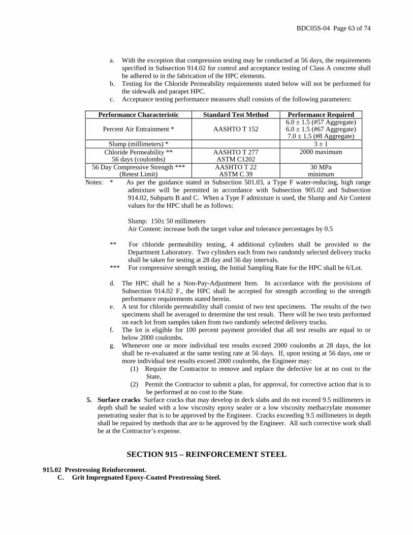
BDC05S-04 Page 63 of 74
a. With the exception that compression testing may be conducted at 56 days, the requirements
specified in Subsection 914.02 for control and acceptance testing of Class A concrete shall be adhered to in the fabrication of the HPC elements.
b. Testing for the Chloride Permeability requirements stated below will not be performed for the sidewalk and parapet HPC.
c. Acceptance testing performance measures shall consists of the following parameters:
Performance Characteristic Standard Test Method Performance Required
Percent Air Entrainment * AASHTO T 152 6.0 ± 1.5 (#57 Aggregate) 6.0 ± 1.5 (#67 Aggregate) 7.0 ± 1.5 (#8 Aggregate)
Slump (millimeters) * 3 ± 1 Chloride Permeability **
56 days (coulombs) AASHTO T 277 ASTM C1202
2000 maximum
56 Day Compressive Strength *** (Retest Limit)
AASHTO T 22 ASTM C 39
30 MPa minimum
Notes: * As per the guidance stated in Subsection 501.03, a Type F water-reducing, high range admixture will be permitted in accordance with Subsection 905.02 and Subsection 914.02, Subparts B and C. When a Type F admixture is used, the Slump and Air Content values for the HPC shall be as follows:
Slump: 150± 50 millimeters Air Content: increase both the target value and tolerance percentages by 0.5
** For chloride permeability testing, 4 additional cylinders shall be provided to the
Department Laboratory. Two cylinders each from two randomly selected delivery trucks shall be taken for testing at 28 day and 56 day intervals.
*** For compressive strength testing, the Initial Sampling Rate for the HPC shall be 6/Lot.
d. The HPC shall be a Non-Pay-Adjustment Item. In accordance with the provisions of Subsection 914.02 F., the HPC shall be accepted for strength according to the strength performance requirements stated herein.
e. A test for chloride permeability shall consist of two test specimens. The results of the two specimens shall be averaged to determine the test result. There will be two tests performed on each lot from samples taken from two randomly selected delivery trucks.
f. The lot is eligible for 100 percent payment provided that all test results are equal to or below 2000 coulombs.
g. Whenever one or more individual test results exceed 2000 coulombs at 28 days, the lot shall be re-evaluated at the same testing rate at 56 days. If, upon testing at 56 days, one or more individual test results exceed 2000 coulombs, the Engineer may:
(1) Require the Contractor to remove and replace the defective lot at no cost to the State,
(2) Permit the Contractor to submit a plan, for approval, for corrective action that is to be performed at no cost to the State.
5. Surface cracks Surface cracks that may develop in deck slabs and do not exceed 9.5 millimeters in depth shall be sealed with a low viscosity epoxy sealer or a low viscosity methacrylate monomer penetrating sealer that is to be approved by the Engineer. Cracks exceeding 9.5 millimeters in depth shall be repaired by methods that are to be approved by the Engineer. All such corrective work shall be at the Contractor’s expense.
SECTION 915 – REINFORCEMENT STEEL 915.02 Prestressing Reinforcement.
C. Grit Impregnated Epoxy-Coated Prestressing Steel.

BDC05S-04 Page 64 of 74
THE FIRST SENTENCE IS CHANGED TO:
Grit impregnated epoxy-coated prestressing steel strands shall conform to the requirements of ASTM A 882 and to the criteria specified in 502.06.
SECTION 917 – STRUCTURAL STEEL AND OTHER FERROUS METALS 917.01 Bolts and Bolting Material.
2. Specifications. THE FOLLOWING IS ADDED:
c. Direct Tension Indicators shall comply with ASTM F 959 and shall be accepted and installed according to Test Method S-3, “Procedure for Identification and Installation of High Strength Bolts with Direct Tension Indicators (DTI’s)”.
3. Manufacturing.
a. Bolts. THE FIRST SENTENCE IS CHANGED TO:
Hardness for bolt diameters 6 millimeters to 13 millimeters, inclusive, shall be as noted: THE FOLLOWING IS ADDED:
When atmospheric corrosion resistant weathering steel is to be used, Type 3 bolts shall be used. THE FOLLOWING IS ADDED:
d. Direct Tension Indicators (DTI’s). When galvanizing of the bolt assembly is required, DTI’s shall be mechanically galvanized in accordance with AASHTO M 298, Class 50 (ASTM B 695, Class 50). DTI’s to be used for Type 3 bolts shall be epoxy coated with a black color.
4. Testing.
THE FOLLOWING IS ADDED:
g. Direct Tension Indicators (DTI’s). DTI’s shall be tested according to ASTM F 959.
7. Installation. THE SUBPART A. IS CHANGE TO:
a. Bolts shall be installed according to the appropriate AASHTO Specifications. Direct Tension Indicators (DTI’s) shall be used with high strength bolts to verify the required tension. The provisions of Article 11.5.6.4.7 of Division II of the AASHTO Standard Specifications or of Article 11.5.6.4.7 of the AASHTO LRFD Bridge Construction Specifications shall be followed. If warranted and as directed by the Engineer, the face of the nut shall be smeared with wax before it is installed. The Castral Stick Wax lubricant, beeswax or a water wax emulsion; such as, the MacDermid “Torque ’N Tension Control Fluid” may be used.
THE FOLLOWING IS ADDED AT THE END OF THE SUBSECTION:
Anchor bolts, rock anchors, and hardware shall conform to AASHTO M 270M Grade 250 and shall be galvanized after fabrication, including threading, according to ASTM A 153.
Dowels used to anchor prestressed concrete voided slabs and box beams to abutments and piers shall conform to AASHTO M 270M Grade 250 and shall be galvanized to ASTM A 153. Threading of dowels is not required.
Welded steel shear connectors shall conform to Division II, Section 11 of the AASHTO Standard Specifications for Highway Bridges or Section 11 of the AASHTO LRFD Bridge Construction Specifications.
Stainless steel bolts, nuts, and washers shall conform to ASTM A 320, Class 1, Grade B8 (AISI Type 304).

BDC05S-04 Page 65 of 74
For overhead and cantilever sign support structures, bolts, nuts and washers for steel to steel chord splices shall conform to AASHTO M 164 and be hot-dip galvanized as per ASTM A 153.
As an alternate, bolts, nuts and washers conforming to AASHTO M 164 may be substituted for bolts, nuts, and washers of the same diameter, length, and thickness conforming to ASTM A 307. 917.03 Castings, Materials and Components for Drainage Structures. THE FIRST PARAGRAPH IS CHANGED TO:
All inlet and manhole castings, grates, extension rings, extension frames and covers shall be capable of withstanding the proof load testing requirements specified in AASHTO M 306 when they are tested as a complete assembled unit and shall conform to the following:
SECTION 919 – MISCELLANEOUS 919.02 Bearing Pads.
A. Elastomeric Bearing Pads. THE FIRST PARAGRAPH IS CHANGED TO:
Elastomeric bearing pads for bridge beams shall conform to Division II, Section 18 of the AASHTO Standard Specifications for Highway Bridges or Section 18 of the AASHTO LRFD Bridge Construction Specifications.
THE FOLLOWING SECTION IS ADDED:
SECTION 921 – FIBERGLASS REINFORCED PLASTIC LUMBER
The furnishing of Fiberglass Reinforced Plastic Lumber (FRPL) shall conform to the following material properties: 1. Plastic. The plastic for FRPL shall be a mixture of one or more of the following recycled post consumer or
post industrial thermoplastics: high-density polyethylene, medium-density polyethylene or, low-density polyethylene. The plastic shall be mixed with appropriate colorants, UV inhibitors and antioxidants so that the resulting product meets the material property requirements specified in Table I below.
FRPL shall not absorb moisture, corrode, rot, warp, splinter or crack. The outer skin shall be smooth and black in color unless otherwise specified in the contract plans. It shall contain hindered amine light stabilizers to provide sufficient resistance to ultraviolet light degradation so as to meet the requirements in Table I below.
2. Manufacturing. Manufacture FRPL as one continuous piece with no joints or splices to the dimensions and tolerances in accordance with Table 2 and consisting of a dense outer skin surrounding a less dense core. Interior voids shall not exceed 19 millimeters in diameter. FRPL shall be free of twist and curvature.
3. Reinforcement. FRPL shall be reinforced by fiberglass reinforcing rods spaced inside the four corners of the timber. Reinforce 254 MM x 254 MM FRPL with a minimum of four 38 millimeters diameter reinforcing rods placed in the corners of the section. Reinforce 305 MM x 305 MM FRPL with a minimum of four 38 millimeters diameter reinforcing rods placed in the corners of the section. Reinforcing rods must be continuous and offer a minimum flexural strength of 483 megapascals when tested in accordance with ASTM D 4476 and a minimum compressive strength of 276 megapascals when tested in accordance with ASTM D 695. Steel reinforcing rods shall not be permitted. All FRPL used for constructing platforms, blocking and wales shall have a minimum of 15% (by weight) chopped glass reinforcement added to the polyethylene. No fiberglass rebar will be required for the smaller dimensional FRPL.
4. Structural Properties. 254 MM x 254 MM and 305 MM x 305 MM FRPL shall meet the minimum structural properties (+/- 10%) listed in Tables 3A and 3B. Smaller, dimensional FRPL for platforms and blocking shall meet the minimum structural properties listed in Table 4.
TABLE 1: PLASTIC MATERIAL PROPERTIES
Density (ASTM D792) Skin 881-1009-kilograms/cubic meter Density (ASTM E1547) Core 54.4-769- kilograms/cubic meter

BDC05S-04 Page 66 of 74
Water Absorption (ASTM D570) Skin 2 hrs: <1.0% wt. increase 24 hrs: <3.0% wt. increase
Brittleness (ASTM D746) Skin No break at -4.4oC Impact Resistance (ASTM D746) Skin Greater than 0.22 N.m/millimeters Hardness (ASTM D2240) Skin 44-75 (Shore D) Abrasion (ASTM D4060) Cycles = 10,000 Wheel = CS17 Load – 1.0 kilograms
Skin Weight Loss: <0.03g Wear Index: 2.5 to 3.0
Chemical Resistance (ASTM D543)
Skin/Core Sea Water Gasoline No. 2 Diesel
<1.5% weight increase <7.5% weight increase <6.0% weight increase
Tensile Properties (ASTM D638) Skin/Core Minimum 3.4 MPa at break Compressive Modulus (ASTM D695) Skin/Core Minimum 276 MPa Coefficient of Friction (ASTM F489) Skin Maximum 0.25, wet or dry Nail Pull-Out (ASTM D1761) Skin/Core Minimum 27 kilograms
TABLE 2: DIMENSIONS AND TOLERANCES
Plastic Timber Dimension Tolerance Length Per order ± 150 millimeters Width See Contract Plans ± 6 millimeters Height See Contract Plans ± 6 millimeters Corner Radius 1.75 millimeters ± 6 millimeters Outer Skin Thickness 0.1875 millimeters ± 3 millimeters Distance from outer surface to rebar elements
1.5 millimeters ± 3 millimeters
Straightness (gap, bend or bulge inside while lying on a flat surface)
<38 millimeters per 1 meter length
TABLES 3-A AND 3-B: STRUCTURAL PROPERTIES
Table 3-A Member Size 254 millimeters x 254 millimeters Modulus of Elasticity as derived below 3592 MPa Stiffness, E.I. 1162 kN-m2
Yield Stress in Bending 40 MPa Weight 45-55 kg/m
Table 3-B Member Size 305 millimeters x 305 millimeters Modulus of Elasticity as derived below 2792 MPa Stiffness, E.I. 1888 kN-m2
Yield Stress in Bending 30 MPa Weight 63-76 kg/m
5. Modulus of Elasticity. Determine the Modulus of Elasticity of a full size specimen by conducting a three
point bend test with a load applied in the center of a simply supported 4267 millimeters span at a deflection rate of 6 millimeters per minute. The Modulus is to be taken at a strain of 0.25 millimeters per millimeters,

BDC05S-04 Page 67 of 74
where strain equals (6) x (depth of cross section) x (deflection) / (span length squared) and where Modulus of Elasticity equals (load) x (span length cubed) / [(48) x (deflection) x (moment of inertia)].
TABLE 4: STRUCTURAL PROPERTIES
Table 4
Modulus of Elasticity (ASTM D6109) 1207 MPa Flexural Strength (ASTM D6109) No fracture at 12 MPa Compressive Strength (ASTM D6108) 10 MPa Compressive Strength Parallel to Grain (ASTM D6112) 12 MPa Compressive Strength Perpendicular to Grain (ASTM D6112) 4 MPa Screw Withdrawal (ASTM D6117) 159 kilograms
The approved manufacturers of FRPL products are listed on the following website:
http://www.state.nj.us/transportation/eng/technology/materials
THE FOLLOWING SECTION IS ADDED:
SECTION 922 – FIBERGLASS REINFORCED PLASTIC PILES
The furnishing of Fiberglass Reinforced Plastic Piles (FRPP) shall conform to the following material properties: 1. Plastic. The plastic for FRPP shall be a mixture of one or more of the following recycled post consumer or
post industrial thermoplastics: high-density polyethylene, medium-density polyethylene or, low-density polyethylene. The plastic shall be mixed with appropriate colorants, UV inhibitors and antioxidants so that the resulting product meets the material property requirements specified in Table I below.
FRPP shall not absorb moisture, corrode, rot, warp, splinter or crack. The outer skin shall be smooth and black in color unless otherwise specified in the contract plans. It shall contain hindered amine light stabilizers to provide sufficient resistance to ultraviolet light degradation so as to meet the requirements in Table I below.
2. Manufacturing. Manufacture FRPP as one continuous piece with no joints or splices to the dimensions and tolerances in accordance with Table 2 and consisting of a dense outer skin surrounding a less dense core. Interior voids shall not exceed 19 millimeters in diameter. FRPP shall be free of twist and curvature.
3. Reinforcement. FRPP shall be reinforced by fiberglass reinforcing rods spaced evenly around the inside perimeter of the pile. Reinforce 254 millimeters OD FRPP with a minimum of six 25 millimeters diameter fiberglass reinforcing rods. Reinforce 330 millimeters OD FRPP with a minimum of twelve 35 millimeters diameter fiberglass reinforcing rods. Reinforce 406 millimeters OD FRPP with a minimum of sixteen 35 millimeters diameter fiberglass reinforcing rods. Reinforcing rods must be continuous and offer a minimum flexural strength of 483 MPa when tested in accordance with ASTM D 4476 and a minimum compressive strength of 276 MPa when tested in accordance with ASTM D 695. Steel reinforcing rods shall not be permitted. All FRPP shall have a minimum of 5% (by weight) chopped glass reinforcement added to the polyethylene.
4. Structural Properties. 254 millimeters OD, 330 millimeters OD and 406 millimeters OD FRPP shall meet the minimum structural properties (+/- 10%) listed in Tables 3A and 3B. The Modulus of Elasticity shall be determined by the test procedure found in Section 6.
5. Recoverable Deflection. FRPP shall exhibit recoverable deflection. FRPP shall not exhibit more than a 5% reduction in bending stiffness (EI) when cyclically load tested. The manufacturer of the FRPP shall provide cyclical, flexural load test results from an independent test laboratory. Cyclical load testing shall be conducted on either the specified 330 millimeters or 406 millimeters FRPP. The test shall be for a minimum of 200 load cycles. The test shall be a four point load condition with a minimum 9.3 meters clear span and a minimum 15' shear span. The applied load shall produce a minimum of 40% of the FRPP's bending moment at yield. The bending moment at yield shall be determined by the formula M = f (I / c) where:
M = bending moment at yield (Newton meter)

BDC05S-04 Page 68 of 74
f = yield stress in bending (megapascals) I = moment of inertia of cross-section (MM4) c = distance from neutral axis to point where stress is desired (millimeters)
TABLE 1: PLASTIC MATERIAL PROPERTIES
Density (ASTM D792) Skin 881-1009- kilograms/cubic meter Density (ASTM E1547) Core 544-769- kilograms/cubic meter
Water Absorption (ASTM D570) Skin
2 hrs: <1.0% wt. increase 24 hrs: <3.0% wt. increase
Brittleness (ASTM D746) Skin No break at -4oC Impact Resistance (ASTM D746) Skin Greater than 0.22 N.m/millimeters Hardness (ASTM D2240) Skin 44-75 (Shore D) Abrasion (ASTM D4060) Cycles = 10,000 Wheel = CS17 Load – 1 kg
Skin Weight Loss: <0.03g Wear Index: 2.5 to 3.0
Chemical Resistance (ASTM D543)
Skin/Core Sea Water Gasoline No. 2 Diesel
<1.5% weight increase <7.5% weight increase <6.0% weight increase
Tensile Properties (ASTM D638) Skin/Core Minimum 3.4 MPa at break Compressive Modulus (ASTM D695) Skin/Core Minimum 276 MPa Coefficient of Friction (ASTM F489) Skin Maximum 0.25, wet or dry Nail Pull-Out (ASTM D1761) Skin/Core Minimum 27 kgs
TABLE 2: DIMENSIONS AND TOLERANCES
FRPP Dimension Tolerance Length Per order (32 meters max) +150MM / -0.0 MM Outside Diameter 254 MM / 327 MM / 413 MM ± 10 MM Outer Skin Thickness 5 MM/ 5 MM / 5 MM ± 3 MM Distance from outer surface to rebar elements (SFRPP) 22 MM /19 MM / 32 MM ± 10 MM
Straightness (gap, bend or inside while lying on a flat surface) <38 millimeters per
3048 millimeters
TABLES 3-A and 3-B: STRUCTURAL PROPERTIES
Table 3-A Member Size 254 MM OD Modulus of Elasticity as derived below 3158 MPa Stiffness, E.I. 6457 kN-m2
Yield Stress in Bending 30 MPa Bending Moment at Yield 47644 N.M Weight 36-43 kg/m
Table 3-B Member Size 330 MM OD Modulus of Elasticity as derived below 7267 MPa Stiffness, E.I. 4247 kN-m2
Yield Stress in Bending 59 MPa Bending Moment at Yield 209994 N.m Weight 67-82 kg/m

BDC05S-04 Page 69 of 74
Table 3-C Member Size 406 MM OD Modulus of Elasticity as derived below 6874 MPa Stiffness, E.I. 9212 kN-m2
Yield Stress in Bending 54 MPa Bending Moment at Yield 357667 N.m Weight 98-121 kg/m
6. Modulus of Elasticity. The Modulus of Elasticity shall be determined by the following test procedure:
a. Place a 16.5 meters long standard commercial type FRPP in a clamping device so that 1.8 meters of
the piling will be firmly fixed and unable to move. b. The opposite end is to simply supported. c. Gradually apply a vertical (downward) load at a point that is 3.7 meters from the simply-supported
end. d. Measure the deflection along the length of the piling at the load point, and 3 equidistant locations. e. Use the load and deflection data to calculate the flexural modulus of elasticity, maximum outer fiber
stress, stiffness (EI), and the bending stress. f. The flexural modulus of elasticity is calculated by dividing EI by the moment of inertia of the cross
section of the product.
Calculate the properties in Table 3A and 3B utilizing standard elastic beam flexure formulas (as found in references such as Machinery’s Handbook; and Formulas for Stress and Strain, by Roark and Young). Report the Stiffness (EI) as the average of the stiffness at all measurement locations, between zero load and half the load corresponding to the specification yield stress. The specified minimum yield stress in bending shall be reached before failure of the product. Calculate the stress at the load point, on the tension side of the plastic composite marine piling.
As stated, conduct the tests on a full-scale product of the specified size. The results of these tests may be extended through engineering calculations, to a product of another size only if the other size has the same or smaller cross section than the tested product. Do not use smaller cross sections to predict the performance of larger cross sections.
7. Wrapping. Wrapping for the FRPP that are to be placed in clusters shall be 13 MM diameter steel cable (16
MM OD covering) polypropylene impregnated wire rope.
The approved manufacturers of FRPP products are listed on the following website:
http://www.state.nj.us/transportation/eng/technology/materials THE FOLLOWING SECTION IS ADDED:
SECTION 923 – FIBERGLASS-CONCRETE COMPOSITE PILES
The Fiberglass-Concrete Composite Piles (FCCP) shall consist of three components: a hollow composite tube, a concrete core and a durable coating. The furnishing of FCCP shall conform to the following material properties:
1. Composite Tubes. Composite tubes shall be produced of composite FRP (Fiber Reinforced Polymer) materials that have been formed by means of pultrusion, filament winding, scrimp, or by other methods of production. E-Glass or other continuous fiber reinforcement shall be incorporated in the shell and shall be impregnated with vinyl ester, polyester, or epoxy resin. The content of the structural wall shall be 50 to 70 percent glass with a minimum of 25 percent resin (by weight). The manufactured tubes shall be capable of withstanding normal handling, shipment, and installation procedures.
The Tubes shall exhibit superior corrosion and ultraviolet resistance as demonstrated when exposed to an accelerated environmental test chamber for not less than 3,600 hours. The tube shall show no structural failure (i.e. <10% loss of strength) as a result of exposure to moisture and lamps required in one of the following: ASTM G152, G155, G154 or B-117.

BDC05S-04 Page 70 of 74
The Tubes to be used in the fabrication of FCCP shall provide sufficient cross section and strength to withstand stresses incurred by fabrication, handling and driving of the piles to the required resistance.
a. Tolerances. Acceptable tolerances for the fiberglass tubes shall be as follows:
Minimum Length (millimeters) plus one meter; minus 0 millimeters Maximum Sweep (millimeters)* 0.08% of total length Ends out of Square (millimeters) 1.0% of diameter
* Sweep – deviation from straightness, measured at several points about the pile circumference
while the pile is not subjected to bending stresses. b. Physical Properties. As defined in ASTM D 2310 or D 2996, fiberglass products designated as
follows shall be used:
Class: RTRP (Reinforced Thermosetting Resin Pipe) Type: Type I (filament wound) Grade: Grade 1 (Glass fiber reinforced epoxy resin pipe),
Grade 2 (Glass fiber reinforced polyester resin pipe) or Vinylester resin.
In the manufacture of fiberglass tubes resins containing ultraviolet (UV) inhibitors shall be
used. A UV resistant film coating of a minimum 3 mils thickness to portions of piles remaining exposed after installation shall be applied. Fiberglass tubes that have the following minimum physical properties shall be used:
Nominal Tube Diameter (millimeters)
12 14 16 axial-tensile1 27580
MPa 23097mpa 2800 MPa
axial-compressive2 19305mpa 16203 MPa
1900 MPa Elastic Moduli (MPa) hoop-tensile3 31026
MPa 31026 MPa
31026 MPa
axial-tensile 483 MPa 400 MPa 338 MPa axial-compressive 269 MPa 241 MPa 200 MPa hoop-tensile 241 MPa 241 MPa 241 MPa Strength (MPa)
Wall thickness 4 MM 5 MM 6 MM 1 ASTM D 2105 2 ASTM D 695 (modified – see Allowable Degradation) 3 ASTM D 1599
c. Allowable Degradation. After exposure to light and water spray or salt spray for a duration of
3600 hours the total UV resistance of resin inhibitors and color film shall be sufficient to limit the loss of their properties to the limits specified below. Certification of exposure testing that has been conducted in accordance with at least one of the following ASTM methods: G 152, G 155, G 154 or B 117 shall be provided to the Engineer.
Property Allowable
loss/change Test Designation axial tensile strength loss ≤ 10% ASTM D 2105 axial compressive strength loss ≤ 10% ASTM D 695 (modified)* hoop tensile strength loss ≤ 10% ASTM D 1599 color film adhesion loss ≤ 10% ASTM D 4541 color change ∆Ε 25 ASTM E 308 and D 2244 * ASTM D 695 may be modified as follows: Test specimen dimensions: diameter: full diameter of tube being tested height: 25 millimeters

BDC05S-04 Page 71 of 74
Note. The compression tool described in ASTM D 695 is not to be used. Center the specimen in the compression test machine and place a steel plate on top of the specimen to evenly distribute the load from the test machine.
2. Dimensional and Physical Stability. Dimensional and physical stability of materials used in the
manufacture of composite piles shall meet the evaluation criteria of ASTM D 696. 3. Color. Color shall be permanent. Color to be provided shall be black or gray. 4. Concrete. As a minimum, concrete infill for FCCP shall conform to Class A concrete strength requirements.
In addition, a positive connection such as either using a composite tube with a textured inside surface, or use of a chemical bonding agent, or by using shrinkage compensating concrete shall be established between the composite tube and concrete core to ensure composite action.
5. Ultimate Flexural Strength. Independent test lab results confirming that the FCCP meet or exceed a 158060 N.m ultimate flexural strength value for a 300 millimeters nominal dimension FCCP shall be submitted to the Engineer. In practice, FCCP should not be designed to their ultimate flexural strength capacity. Due to the strain limitations of concrete in tension, a factor of safety should be applied. For cyclically loaded bridge pier protection applications, FCCP should not be loaded beyond 50% of their ultimate flexural strength or 79030 N.m
6. Wrapping. Wrapping for the FCCP that are to be placed in clusters shall be 13 MM diameter steel cable (16 MM OD covering) polypropylene impregnated wire rope.
The approved manufacturers of FCCP products are listed on the following website:
http://www.state.nj.us/transportation/eng/technology/materials
SECTION 990 – METHODS OF TESTS Test Method S-2 S-2 PROCEDURE FOR PERFORMING ROTATIONAL-CAPACITY TEST ON BOLTS TOO SHORT TO FIT
TENSION CALIBRATOR. B. Procedure.
7. THE LAST SIX PARAGRAPHS ARE REMOVED. THE FOLLOWING IS ADDED: Test Method S-3
S-3 PROCEDURE FOR VERIFICATION AND INSTALLATION OF HIGH STRENGTH BOLTS WITH DIRECT TENSION INDICATORS (DTI’s).
I. Verification of DTI Performance
Verification of DTI performance is required prior to installation of bolts in the work. In bridge work the manufacturers are typically specifying smaller gaps in the spaces between the protrusions on the washer than normally used in other construction or in the gap specified for testing in the product specification ASTM F 959. The basic principle used in this verification test is to make sure that there is a DTI gap when the test tension is 1.05 times greater than the job installation tension requirement. The following verification procedure shall be used:
A. Equipment Required:
1. Calibrated bolt tension measuring device with a special flat insert in place of normal bolt head holding insert. Special insert required to allow access to measure DTI gap.
2. Tapered leaf thickness (feeler) gage 0.127 millimeters. Same gage as to be used to inspect the bolts after
installation.

BDC05S-04 Page 72 of 74
3. Bolts, nuts, and standard washers to be used in the work with the DTI’s.
4. Impact and manual wrench to tighten bolts. Equipment should be the same as to be used in the work.
B. Verification Test Procedure: (Test three seats for each RC lot and position of DTI)
1. Install bolt, nut, DTI and standard washer into bolt tension measuring device. Assembly should match that to be used the work.
2. Use another wrench on the bolt head to prevent rotation of the head against the DTI if the DTI is to be used
under the unturned element.
3. Tighten bolt to tension listed below (1.05 times the minimum installation tension). Use another wrench on the bolt head to prevent rotation of the head against the DTI if the DTI is to be used under the unturned element. If an impact wrench is used, tighten to a load slightly below the required load and use a manual wrench to attain the required tension. The load indicating needle of the bolt calibrator cannot be read accurately when an impact wrench is used.
(3)Bolt Tension, kN
Bolt Size (millimeters) 13 16 20 22 24 27 30
M164 (A325) Bolts 58 89 129 182 240 262 334
(3) Bolt Tension equals 1.05 (Min. Installation Tension)
4. Determine and record the number of spaces between the protrusion on the DTI that a 0.127 millimeters thickness gage is refused. The total number of spaces in the various sizes and grade of DTI’s is shown below.
Number of Spaces on DTI
Bolt Diameter
Millimeters 13 16 20 22 24 27 30
M164 (A325) Bolts 4 4 5 5 6 6 7
5. The number of spaces which the 0.127 millimeters thickness gage is refused should not exceed the number
given in the table below. If the number of spaces exceeds the number in the table, the DTI fails the verification test.
Verification Criteria*
Number of spaces in washer 4 5 6 7 8 9
Max. number of spaces gage is refused 1 2 2 3 3 4
* If the test is a coated DTI under the turned element, the maximum number of spaces that the gage
is refused is the number of spaces on the washer minus one.

BDC05S-04 Page 73 of 74
6. The bolts should be further tightened to the smallest gap to be allowed in the work. Normally, this smallest gap condition is achieved when the gaps at all the spaces are less than 0.127 millimeters (or a gap size as approved by the Engineer) and not all gaps completely closed. When such a condition is achieved, the 0.127 millimeters thickness gage is refused at all spaces but a visible gap exists in at least one space. Note the load in the bolt at the smallest gap. The bolts in this installation verification test and in the actual installation should not be tightened to a no visible gap condition when all the gaps are completely closed. The load in the bolt becomes indeterminate when no gap exists. It is possible to cause failure by tightening beyond complete crushing of the washer. The bolt load at this smallest gap should not cause excessive permanent inelastic deformation of the fastener. The degree of inelastic deformation is judged by removing the fastener from the test apparatus and turning the nut by hand the full length of the threads on the bolt after the test.
7. Remove the bolt from the calibrator and turn the nut on the threads of the bolt by hand. The nut should be
able to be turned on the complete length of the threads, excluding the thread runout. Alternatively, if the nut is unable to go the full length, but the load at the minimum DTI gap (measured in step 6 above) is less than 95% of the bolt tension recorded at the nut rotation required for the rotational-capacity test, the assembly, including the DTI, is deemed to have passed the test. If the nut cannot be run the full thread length, and if the load at the smallest gap condition is greater that the 95% of the bolt tension recorded at the nut rotation required for the rotational-capacity test, the load required for the smallest gap in step 6 is too large and the DTI lot shall be rejected.
Short Bolts
Bolts from Rotational Capacity (RC) lots too short to fit in the tension measuring device shall be tested
in accordance with Test Method S-2 of these Specifications by tightening to the minimum DTI gap (measured in step 6 above) and checked in accordance with step 7. The 95% alternative cannot be used since short bolts are not tested in the tension measuring device for rotational capacity. The DTI used with the short bolt should be checked in accordance with step 1 through 5 using a longer bolt in the tension measuring device.
II. Installation
1. The use of a DTI under the unturned bolt head requires that the element bearing against the DTI not turn. Two men are required: One to operate the wrench, and the other to prevent turning of the element with the DTI and to monitor the gap. If the DTI is used under the turned element, an additional hardened washer must be used between the turning element and the protrusion on the DTI.
2. Snug the connection to compact the joint. The DTI should be inspected after snugging and the gaps checked.
If the number of spaces in which the 0.127 millimeters thickness gage is refused exceeds the value in the table shown above in step 5 of the verification test, the bolt must be removed and another DTI installed. The bolt should be resnugged.
3. Tighten the bolts systematically to the inspection gap. The number of spaces in which the 0.127 millimeters
thickness gage is refused should be equal or greater than the number shown in the table below. Tightening beyond the smallest gap established above in steps 6 and 7 is not allowed. Bolts which have a DTI with a smaller gap or no gap shall be replaced and the bolts tightened with a new DTI.
Inspection Criteria *
Number of spaces in washer 4 5 6 7 8 9
Minimum spaces gage is refused 2 3 3 4 4 5
* The gage shall be refused in all spaces when a coated DTI is used under the turned element.

BDC05S-04 Page 74 of 74
Implementation Code R (ROUTINE) Changes must be implemented in all applicable Department projects scheduled for Final Design Submission at least one month after the date of the BDC announcement. This will allow designers to make necessary plan, specifications, and estimate/proposal changes without requiring the need for an addenda or postponement of advertisement or receipt of bids. Recommended By:
Approved By:
ORIGINAL SIGNED
ORIGINAL SIGNED
Lynn D. Rich Director, Quality Management Services
F. Howard Zahn Assistant Commissioner, Capital Program Management
LDR:KS:HVP BDC05S-04.doc


![DEPARTMENT OF EDUCATION PO Box SOO TRENTON, N] 08625 … · Little Ferry, NJ 07643-1756 • Re: Long-Range Facilities Plan Final Determination . Dear Mr. Scarafile: The Department](https://img.dokumen.tips/doc/110x75/5e829554a8c53716447b92eb/department-of-education-po-box-soo-trenton-n-08625-little-ferry-nj-07643-1756.jpg)