Embed Size (px)
Citation preview

Operation Manual
© CEDES Safety & Automation AG Version 1.8 / 02. August 2011 Part No. 103 373 E ID: 2000055149
Safe200 Safe400
Safety Light Curtain
Active Optoelectronic Protective Device (AOPD) type 2 (Safe200) or type 4 (Safe400) Type 2 / 4 according IEC 61496-1/-2
Category 2 / 4, PL c /e according EN ISO 13849-1 SIL 1 / 3 according IEC61508-1/-7 SIL CL 1 / 3 according EN 62061
English
IMPORTANT NOTE
FOLLOW THE INSTRUCTIONS GIVEN IN THIS MANUAL CAREFULLY. FAILURE TO DO SO MAY CAUSE CUSTOMER COMPLAINTS AND SERIOUS CALL BACKS. KEEP INSTRUCTION MANUAL ON SITE.
With the Safe400 safety light curtain, CEDES sets a new best mark for compactness.
Because of its flexibility, Safe400 guarantees use in the most varied of applications.

Safe200 / Safe400 Operation Manual
2 www.cedes-sa.com © CEDES Safety & Automation AG
Content 1. Approvals and conformity..................... 2 2. Introduction........................................... 3
2.1. System design..........................................3 2.2. Special features .......................................3
3. Applications and conditions.................. 4 3.1. Areas of Application.................................4 3.2. Application Restrictions.............................4 3.3. Application Conditions .............................5
4. Principles of operation.......................... 5 4.1. LED indicators..........................................5 4.2. Cascading using extension modules..........6 4.3. Perimeter system......................................7
5. Installation ............................................ 7 5.1. Regulations and standards .......................7
5.1.1. Safety distance to danger point .........7 5.1.2. Height of protective field ...................8 5.1.3. Response time - light curtain .............8 5.1.4. Response time – safety control units ...8 5.1.5. Distance to reflective surfaces............9 5.1.6. Multiple light curtain arrangement.....9 5.1.7. Mounting brackets..........................10 5.1.8. Robust Profile .................................11 5.1.9. Alignment procedure ......................12
5.2. Electrical installation...............................12 5.2.1. Connection diagram.......................12 5.2.2. Test ...............................................12 5.2.3. Power supply..................................13 5.2.4. Bringing into operation ...................13 5.2.5. Outputs .........................................13 5.2.6. Trouble shooting ............................13
6. Blanking functions .............................. 14 7. Height measurement .......................... 15 8. Dimensional drawings ........................ 16
8.1. System with one protective field ..............16 8.2. Cascaded systems..................................17
9. Selection of a safety light curtain........ 18 9.1. Check list ..............................................18 9.2. Selection table (14 mm resolution) ..........19 9.3. Selection table (30 mm resolution) ..........19 9.4. Cascaded systems..................................20 9.5. Accessories / components ......................20
10. Inspection and Service ........................ 21 10.1. Cleaning ...............................................21 10.2. Inspections ............................................21 10.3. Decommissioning ..................................21
11. Product labels...................................... 21 12. Technical data ..................................... 22 13. Index ................................................... 23 14. Certificates........................................... 24
14.1. TÜV.......................................................24 14.2. UL.........................................................26 14.3. CE ........................................................28
1. Approvals and conformity
TÜV Rheinland GmbH performed the CE-type examination according to the machinery directive EC/98/37, appendix 4 and the respective standards IEC 61496. The CE-conformity declaration and the product approval certification (TÜV) is printed in chapter 0 or is available at your nearest CEDES dealer.
Warning Safe200 and Safe400 are only a safety protection device if all instructions in this manual and in the related documents are carefully followed and fully complied with. In addition the installer is responsible to comply with all local laws and standards. Should some of these instructions not be carefully followed, serious injury or death may occur. The in-staller or system integrator will be fully responsible for a safe integration of the light curtain. This instruction manual is part of the light curtain Safe200 or Safe400. It must be kept accessible during the whole life cycle for all personnel who are responsible for installation, operation, maintenance and safety control. Safe200 or Safe400 systems have to be connected with the dedicated connection cables (Table 4). Other cables or a manipulation of the dedicated cables may lead to a loss of the safety function.
Operation Manual Safe200 / Safe400
© CEDES Safety & Automation AG www.cedes-sa.com 3
2. Introduction
Safe200 or Safe400 light curtains are Active Optoelectronic Protective Device (AOPD). Installed rigidly in a machine, it will detect interference or the entry of operating personnel and can in this way safeguard dangerous areas before unauthorized interference or entry can occur. One of the special characteristics of the system is its extremely narrow construction. Another, is that the protection area of this light curtain can be configured in combination with a CEDES safety control unit (SafeC 200, SafeC400, SafeCIS3), accordingly for the specific demand of an application. A Safe200 or Safe400 system complies to annex IV of the European Machinery Directive 2006/42/EG and is a certificated. In order to satisfy safety category 2, a Safe200 light curtain must be connected to a SafeC 200 control unit. To obtain a safety category 4, a Safe400 light curtain must be connected to a SafeCIS3 or SafeC 400 control unit. Further the safety light curtain Safe400 in conjunction with the safety control unit SafeCIS3 fulfills • Type 4 according with IEC 61496-1, -2 • Category 4, PL e according EN ISO 13849-1 • SIL 3 according IEC 61508 • SIL CL 3 according EN 62061
Safe200 in conjunction with the safety control unit SafeC 200 fulfills • Type 2 according with IEC 61496-1, -2 • Category 2, PL c according EN ISO 13849-1 • SIL 1 according IEC 61508 • SIL CL 1 according EN 62061 SafeC 200, SafeC 400 and SafeCIS3 control units accept the outputs of all standard safety components such as light curtains, emergency stop buttons, two hand controls or interlock switches.
2.1. System design
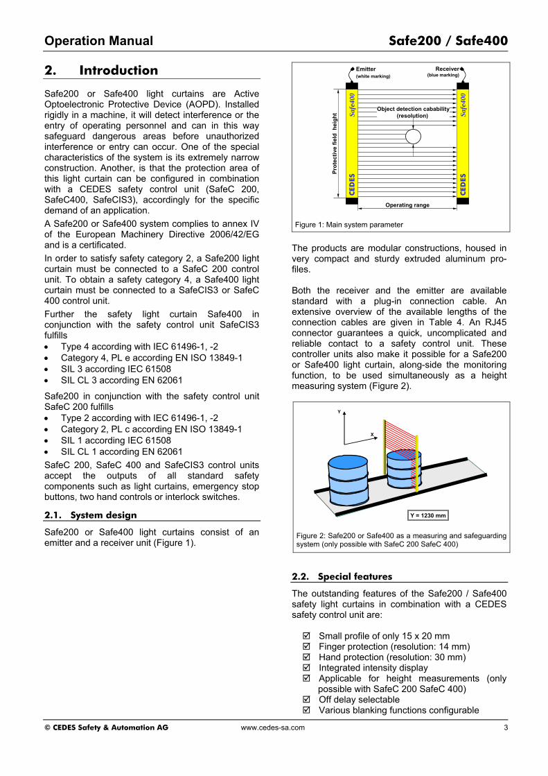
Safe200 or Safe400 light curtains consist of an emitter and a receiver unit (Figure 1).
CED
ESSa
fe40
0
Emitter(white marking)
Receiver(blue marking)
CED
ESSa
fe40
0
Object detection cabability(resolution)
Operating range
Prot
ectiv
e fie
ld h
eigh
t
Figure 1: Main system parameter
The products are modular constructions, housed in very compact and sturdy extruded aluminum pro-files. Both the receiver and the emitter are available standard with a plug-in connection cable. An extensive overview of the available lengths of the connection cables are given in Table 4. An RJ45 connector guarantees a quick, uncomplicated and reliable contact to a safety control unit. These controller units also make it possible for a Safe200 or Safe400 light curtain, along-side the monitoring function, to be used simultaneously as a height measuring system (Figure 2).
X
Y
Y = 1230 mm
Figure 2: Safe200 or Safe400 as a measuring and safeguarding system (only possible with SafeC 200 SafeC 400)
2.2. Special features
The outstanding features of the Safe200 / Safe400 safety light curtains in combination with a CEDES safety control unit are:
Small profile of only 15 x 20 mm Finger protection (resolution: 14 mm) Hand protection (resolution: 30 mm) Integrated intensity display Applicable for height measurements (only
possible with SafeC 200 SafeC 400) Off delay selectable Various blanking functions configurable

Safe200 / Safe400 Operation Manual
4 www.cedes-sa.com © CEDES Safety & Automation AG
Safety function manually mutable Big dynamic area; 0 m to 5 m with a very
compact design Profile length up to 1'200 mm (15 x 20mm) Profile length up to 2'200 mm with robust
profile (40 x 30 mm) Protective field height; in steps of 50 mm
selectable Max. number of beams: 255 Large product diversity regarding resolution,
protective field height and application Unaffected by dust and dirt Easy installation Maintenance free
3. Applications and conditions
3.1. Areas of Application
Safe200 or Safe400 systems can be used as (Figure 3):
Point-of-operation safeguarding Combination of height measuring and point-of
operation safeguarding Hazard area safeguarding Entry safeguarding (entry or exit) Combination of entry and hazard area safe-
guarding Combination of entry, point-of-operation and
hazard area safeguarding Typical areas of application are:
Robotic assembly lines Welding robots Storage facilities Automated assembly stations Small presses Automated conveyor belts
In different industries:
Automotive Apparatus Semiconductor materials Metal processing Paper processing Wood processing Glass manufacturing Textile
And anywhere working personnel need protection from dangerous machinery.
3.2. Application Restrictions
The application of a Safe200 or Safe400 system is not intended for the following usage:
• In an explosive environment (EX), • in radioactive areas or • outside of a temperature range of 0 … 55°C.
Entry safeguarding
Point-of-operation safeguarding
Hazard area safeguarding
Figure 3: Areas of applications

Operation Manual Safe200 / Safe400
© CEDES Safety & Automation AG www.cedes-sa.com 5
3.3. Application Conditions
The correct use of a Safe200 or Safe400 requires certain precautions:
1. The control unit of the machine or system must be able to be electrically stopped and the stop time must be known.
2. The hazardous moving parts of the machine must always be stoppable and must achieve a safe position or complete standstill within the specified stop time of the machine.
3. When installing your Safe200 or Safe400, it must be ensured that over-reach, under-reach, or unprotected areas are impossible, by taking appropriate measures.
Figure 4: Correct applications
Figure 5: Incorrect applications
For the professional installation and operation, please consult the relevant laws and regulations. The safety officer of the manufacturing facility, the local authorities (OSHA in USA, HSE in GB), or the respective industry associations as well as the intensively trained CEDES employees are available for any safety related queries.
4. Principles of operation
The emitter sends coded infrared light pulses (940 nm) to the receiver, which evaluates them. If an object at least the size of the resolution of the system penetrates the protective field, at least one light beam is interrupted. This interruption is evaluated by the CEDES safety control unit and leads to the opening of the configured safety contacts. Whether the safety contact should re-close automatically or manually, is controlled by the configuration of the safety control unit. For the configuration see: • "Operation manual for SafeC 200 / SafeC 400"
(part number: 103 415) • "Operation manual for SafeCIS3 (part number:
104 720) and • Software description "Configuration Tool" (part
number: 105 784)
4.1. LED indicators
There is an integrated red and a green LED in the connection module to each profile (near the cable), which signals the status of the protective field clearly (Figure 6).
Figure 6: LED display
Table 1: LED meanings
LED Description Color Meaning Off Light curtain interrupted
Green Light curtain OK Green Light curtain not interrupted
Green Flashing Intensity inadequate
Off Light curtain not interrupted
Red Red Light curtain interrupted
Light curtain status
Red Flashing Error
All indicators relevant to the control of light curtain systems are situated directly on the CEDES safety control unit (see operation manual SafeC 200 / SafeC 400, (part number: 103 415) or operation manual SafeCIS 3 (part number 104 720)). Note: In cascaded systems only the LED in the first safety light curtain will illuminate (closest to the safety controller).
LED

Safe200 / Safe400 Operation Manual
6 www.cedes-sa.com © CEDES Safety & Automation AG
4.2. Cascading using extension modules
For simpler connection between neighbouring protective fields, the Safe200 or Safe400 light curtain can be easily cascaded using extension modules (Figure 7). One such cascaded system allows the connection of e.g. front, back and topsides of a machine using only one light curtain system. The individual cascaded elements can be connected quickly and simply using the convenient plug-in connectors. Only the following limitations need to be considered: • A maximum of 255 light beams per controller • Protection area extensions in multiples of 50
mm • 10 m maximum total length for light curtains,
extension modules and connection cable combined (Figure 8)
• Only a CEDES prefabricated cable may be used between the light curtain and the SafeC 200, SafeC 400 or SafeCIS3 controller.
The extension modules are connected to the main system via plug-in connection cables. The customer defines:
• Length of the connection cable • Main system (protective field height) • Length of the extension cable and • Extension modules (protective field height)
Accessories, for example, a complete mounting kit or test rods, are provided standard with every delivery.
Due to safety reasons it is necessary that combined light curtains, as they are described above, are configured and tested at the factory as a complete system. Note: In cascaded systems only the LED in the first safety light curtain will illuminate (closest to the safety controller).
Extension cables
System length: 1 x length of connection cable + 1 x protective field length front side + 1 x length of extension cable + 1 x protective field length back side -------------------------------------------------------- Total length (maximum 10 m)
Figure 8: Connection of the back and front sides of a machine with only one Safe200 or Safe400 cascading system. The total length of the system is equal to the individual protective field lengths, plus connection and extension cables added together.
CED
ESSa
fe40
0
CED
ESSa
fe40
0
CED
ESSa
fe40
0
CED
ESSa
fe40
0
CED
ESSa
fe40
0
CED
ESSa
fe40
0
Figure 7: Example for standard and cascading systems

Operation Manual Safe200 / Safe400
© CEDES Safety & Automation AG www.cedes-sa.com 7
4.3. Perimeter system
According to the standard ISO 13855 is to build vertical entry safeguarding systems with the Safe400 safety light curtain. These types of safety systems are typically built using multiple single through beam sensors. Such systems are composed of active and passive modules in one compact profile. Safe400 perimeter light curtains are
built using 50 mm modules (each contains 2 emitter or receiver elements). The distances shown in Figure 9reflect the middle point of the respective 50 mm modules. The protective field respectively the active modules, are clearly recognized as grey / silver surfaces with integrated optical lenses. The not monitored areas (passive areas) are also clearly indicated as black surfaces.
400
900
Dis
tanc
e to
refe
renc
e pl
ane
[mm
]
Reference p lane (e .g . ground)0
300
1100D
ista
nce
to re
fere
nce
plan
e [m
m]
Reference plane (e.g. ground)0
700
300
1200
Reference plane (e.g. ground)0
600
900
Dis
tanc
e to
refe
renc
epl
ane
[mm
]
Figure 9: Perimeter 2, 3 und 4 beams, in accordance with ISO 13855 [2010]
5. Installation
5.1. Regulations and standards
The compliance with the fundamental health & safety requirements as detailed in the EU Machinery Directive 2006/42/EG and control reliability according to OSHA 29 CFR 1910.212, ANSI B11.19 and ANSI B11.20 has to be achieved with the correct implementation of safety components. With the help of a hazard analysis as laid out in DIN EN ISO 12100-1/-2 and EN ISO 14121-1, a comprehensive safety evaluation has to be made when designing and planning machinery and machinery control equipment. If Active Optoelectronic Protective Devices (AOPD) are used, the required safety distances, sufficient protective height and all application conditions must be considered during the planning phase.
5.1.1. Safety distance to danger point
According to the standards, the Safe200 / Safe400 light curtain and the point of danger must be separated by a defined safety distance. This minimum distance safeguards that the danger point may only be reached after the hazardous motion has stopped. The safety distance (see also standards DIN EN ISO 13857, ISO EN 10218, ISO 13855) depends on:
• Machine stop time • Response time of the protective device (light
curtain + safety control units) • Resolution of the protective device • Approaching speed to the danger point
• Position of the AOPD
The approaching speed is dependent on safety distance S as follows
S ≤ 500 mm, speed = 2 mm / ms S > 500 mm, speed = 1.6 mm / ms
In cases of 'vertical' installation of the light curtains within an industrial environment and a resolution of the light curtain system d, (where 14 mm ≤ d ≤ 40 mm), the safety distance S to the point of danger is calculated according to the formula:
For 100 mm ≤ S ≤ 500 mm: S = 2 mm / ms x T + 8 x (d - 14)
For S > 500 mm S = 1.6 mm / ms x T + 8 x (d - 14)
S = Safety distance in mm T = Total response time in ms (machine stop time +
Safe200 / Safe400 response time + SafeC 200 / SafeC 400 / SafeCIS3 controller response time + any configured delay time)
d = Resolution of Safe200 / Safe400 in mm
In the case of perimeter systems (chapter 4.3) for light curtain systems with a resolution d > 40 mm the safety distance is calculated for vertical mounted light curtains and horizontal approach, according to the formula:

Safe200 / Safe400 Operation Manual
8 www.cedes-sa.com © CEDES Safety & Automation AG
S = 1.6 mm / ms x T + 850 [mm]
More detailed information regarding safety distance and safety height can be found in ISO 13855 or DIN EN 13857, depending on mounting type of application.
Important information: The physical resolution of a Safe200 or Safe400 light curtain system is calculated by the distance from lens to lens + the lens diameter. This resolution can be found on the product label. Likewise the resolution can be obtained through the software of the connected CEDES safety control unit. If then the operation mode is set to static or floating blanking (chapter 6), the safety distance must be adjusted according to the new resolution and the new response time. The current resolution is always found on the last configuration print-out of the safety control unit.
5.1.2. Height of protective field
The protective field is clearly visible on the emitter and receiver portion of the light curtain, as the blue / silver area with the optical lenses. The protective field height L and the standard resolution d can be taken from the product label and the selection table of chapter 9.2 and 9.3. The measurements of the Safe200 or Safe400 profile end caps (Figure 21) are chosen so that the resolution can extend to the end of the light curtain (Figure 10). Depending on the application it must be checked, whether possible mirroring (e.g. a table top) has an effect on this resolution (chapter 5.1.5).
CED
ES S
afe4
00
14 mm CED
ES S
afe4
00
Figure 10: Resolution at the end of the light curtain (assuming no mirrored reflections)
When selecting or installing a light curtain, the pre-requisites outlined in Figure 4 must be kept. More detailed information regarding installation height is described in DIN EN ISO 13857 and DIN EN ISO 13855.
5.1.3. Response time - light curtain
The Safe200 and Safe400 light curtain system has two basic different operating modes:
1. Without blanking (standard) 2. With blanking (according to configuration)
The standard response time (reaction time) of the light curtain (tR-BWS) is dependant on the physical resolution and is shown on the product label. An overview of the resolution table is also given in chapter 9.2 and 9.3. CEDES offers additionally the possibility, using the software "Configuration Tool", to determine the response time of all possible Safe200 and Safe400 systems, with a simple mouse-click.
Important information: The response time of the Safe200 or Safe400 light curtain systems are dependent on the operating mode. This means, depending on the operating mode of the SafeC 200 or SafeC 400 control unit, the "Blanking" function may be activated (chapter 6). If this is the case, a new, longer response time applies. This longer response time is visible after a configuration, on the configuration control document. This new response time for the blanking operating mode must be attached to the light curtain in a clearly visible manner (Figure 19). The minimum safety distance from the danger point to the light curtain for the current operating mode may never be under-cut, and when modified, must be adapted to reflect any changes to the response time and resolution. The total light curtain response time for cascaded light curtains (extensions) is the sum of of the response times of each cascade.The declared response times are worst case values. The effectual response depends from the connected control unit and its configuration. The response time may be faster and can be taken form the configuration software tool (103 262) of the corresponding control unit.
5.1.4. Response time – safety control units
The response time of CEDES safety control units is described in the corresponding configuration control document. With the help of an OptiLink it is also possible, to delay the response time of a controller unit. If a controller unit is reconfigured, a new configuration control document must be printed and is always stored near to the control unit.
Important safety advice: A detailed explanation, including the corresponding safety information, for configuring a SafeC 200 / SafeC 400 controller module may be found in the "Configuration Tool" program manual (part number: 105 784). After configuring one of the blanking functions, it is necessary to attach the intended label to the light curtain (see operation manual SafeC 200 / SafeC 400, part number: 103 415). For configurations with a SafeCIS3 control unit, refer to the "Safety Configurator SafeCIS3" manual (part number 105 784) and the SafeCIS3 operation manual (part number: 104 720)
Operation Manual Safe200 / Safe400
© CEDES Safety & Automation AG www.cedes-sa.com 9
5.1.5. Distance to reflective surfaces
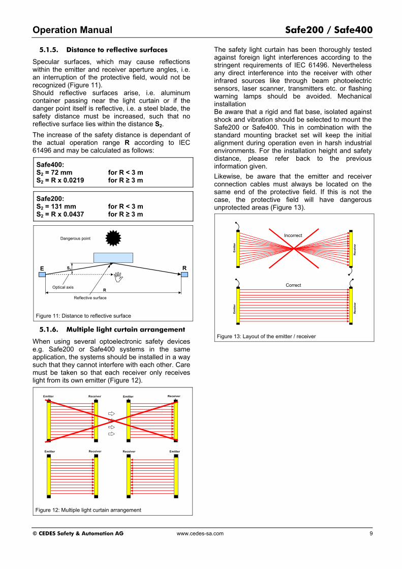
Specular surfaces, which may cause reflections within the emitter and receiver aperture angles, i.e. an interruption of the protective field, would not be recognized (Figure 11). Should reflective surfaces arise, i.e. aluminum container passing near the light curtain or if the danger point itself is reflective, i.e. a steel blade, the safety distance must be increased, such that no reflective surface lies within the distance S2.
The increase of the safety distance is dependant of the actual operation range R according to IEC 61496 and may be calculated as follows:
Safe400: S2 = 72 mm for R < 3 m S2 = R x 0.0219 for R ≥ 3 m
Safe200: S2 = 131 mm for R < 3 m S2 = R x 0.0437 for R ≥ 3 m
Dangerous point
Reflective surface
E R
Optical axis
S2
R
Figure 11: Distance to reflective surface
5.1.6. Multiple light curtain arrangement
When using several optoelectronic safety devices e.g. Safe200 or Safe400 systems in the same application, the systems should be installed in a way such that they cannot interfere with each other. Care must be taken so that each receiver only receives light from its own emitter (Figure 12).
Receiver EmitterEmitter Receiver
Emitter Receiver EmitterReceiver
Figure 12: Multiple light curtain arrangement
The safety light curtain has been thoroughly tested against foreign light interferences according to the stringent requirements of IEC 61496. Nevertheless any direct interference into the receiver with other infrared sources like through beam photoelectric sensors, laser scanner, transmitters etc. or flashing warning lamps should be avoided. Mechanical installation Be aware that a rigid and flat base, isolated against shock and vibration should be selected to mount the Safe200 or Safe400. This in combination with the standard mounting bracket set will keep the initial alignment during operation even in harsh industrial environments. For the installation height and safety distance, please refer back to the previous information given.
Likewise, be aware that the emitter and receiver connection cables must always be located on the same end of the protective field. If this is not the case, the protective field will have dangerous unprotected areas (Figure 13).
Rec
eive
r
Emitt
er
Rec
eive
r
Correct
Emitt
erIncorrect
Figure 13: Layout of the emitter / receiver
Safe200 / Safe400 Operation Manual
10 www.cedes-sa.com © CEDES Safety & Automation AG
5.1.7. Mounting brackets
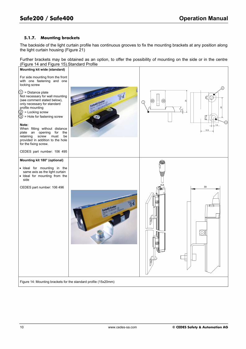
The backside of the light curtain profile has continuous grooves to fix the mounting brackets at any position along the light curtain housing (Figure 21) Further brackets may be obtained as an option, to offer the possibility of mounting on the side or in the centre (Figure 14 and Figure 15).Standard Profile Mounting kit wide (standard) For side mounting from the front with one fastening and one locking screw 1 = Distance plate Not necessary for wall mounting (see comment stated below), only necessary for standard profile mounting 2 = Locking screw 3 = Hole for fastening screw Note: When fitting without distance plate an opening for the retaining screw must be provided in addition to the hole for the fixing screw. CEDES part number: 106 495
25
5
Ø 4
.5M
4
20
12.9
1.9
3
1
2
3
Mounting kit 180° (optional) • Ideal for mounting in the
same axis as the light curtain • Ideal for mounting from the
side CEDES part number: 106 496
39
Figure 14: Mounting brackets for the standard profile (15x20mm)
Operation Manual Safe200 / Safe400
© CEDES Safety & Automation AG www.cedes-sa.com 11
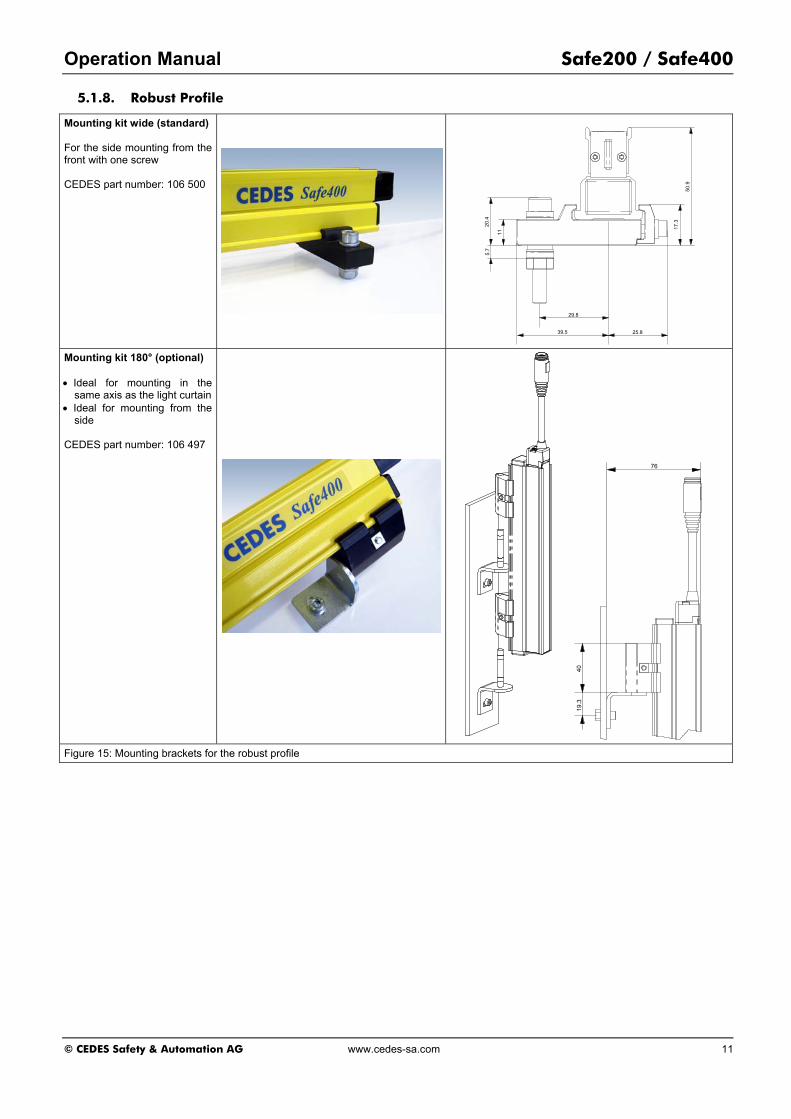
5.1.8. Robust Profile
Mounting kit wide (standard) For the side mounting from the front with one screw CEDES part number: 106 500
50.9
39.5 25.8
29.8
20.4
11
17.3
5.7
Mounting kit 180° (optional) • Ideal for mounting in the
same axis as the light curtain • Ideal for mounting from the
side CEDES part number: 106 497
76
4019
.3
Figure 15: Mounting brackets for the robust profile

Safe200 / Safe400 Operation Manual
12 www.cedes-sa.com © CEDES Safety & Automation AG
5.1.9. Alignment procedure
The alignment procedure can be made easier with the use of integrated indicator diodes (Table 1).
1. Mount the emitter and receiver with the previously mentioned brackets. Make sure that the longitudinal axis of both are oriented parallel. For a vertical or horizontal mounting a level might help to find the correct position.
2. Take care that the receiver and emitter are oriented in the same direction. This means, the beginning of the protective field which is found next to the cable which leads to the CEDES safety control unit, must be located at the same end of the protective field. It is not allowed to mount the Safe200 or Safe400 systems turned 180° (Figure 13).
3. After aligning the longitudinal axis of the emitter and receiver, rotate the receiver along the longitudinal axis to find the receiving angle. During rotation, the receiving angle is shown by the illumination of the green LED in the Safe200 or Safe400 light curtain. If this green diode is blinking, the amount of light detected by the receiver is not sufficient for stable operation. After realigning the light curtain, the protective field must be briefly interrupted. After removing the object from the protective field, a sufficient intensity level is indicated by the illumination of the green LED in the light curtain.
4. Adjust and mount the receiver at the centre of this operating angle.
5. After aligning the receiver, rotate the emitter to find the emitting angle. During rotation, the emitting angle is shown by the illumination of the green LED in the Safe200 or Safe400 light curtain.
6. Adjust and mount the emitter at the centre of this operating angle.
7. Control the protective function of the Safe200 or Safe400 light curtain by using the test rod, according to Figure 16. The insertion of this rod into the protective field at any position has to lead to a protective field interruption (illumination of the red LED in the Safe200 or Safe400 light curtain).
8. It is possible to operate the Safe200 or Safe400 system with a blanking configuration. In addition to the reduced resolution, it is important to note that the safety distance must reflect the newly configured resolution and the new response time (see chapter 5.1.1).
9. When installing a perimeter system (chapter 4.3), you need to note additionally, that it adhere to the EN 999 recommended control heights.
Emitt
er
Rec
eive
r
Figure 16: Correct testing of a protective field using a test rod
5.2. Electrical installation
5.2.1. Connection diagram
The connection of a Safe200 or Safe400 to a machine controller must occur using a SafeC 200 / SafeC 400 or a SafeCIS3 control unit (Figure 17). A quick and comfortable connection is guaranteed using connection cables provided by CEDES (Table 4).
Important safety advice: Safe200 or Safe400 systems have to be connected with the dedicated connection cables (Table 4). Other cables or a manipulation of the dedicated cables may lead to a loss of the safety function
The connectors are color coded: White – Emitter (E= Emitter) Blue – receiver (R= Receiver)
Figure 17: CEDES safety control units for the Safe200 or Safe400 light curtains
For the protection of connectors there are safety clamps (Figure 21) included with every cable delivery.
5.2.2. Test
According to EN 13849-1 when connecting a SafeC 400 or SafeCIS3 control unit in the context of a risk assessment it may not be necessary to conduct tests with a higher level controller.

Operation Manual Safe200 / Safe400
© CEDES Safety & Automation AG www.cedes-sa.com 13
In contrast, according to EN 13849-1, the SafeC 200 safety control unit must be tested within each machine cycle and such a controller must have an output which indicates a possible breakdown (soldering of the contacts), respectively transmits this information to a higher level controller.
Important safety advice: With all Safe200 light curtain systems that are used in conjunction with a SafeC 200 unit, the status con-tact L10 should be connected to the machine controller so that the possibility of a breakdown of the safety contacts is communicated. Within each machine cycle, i.e. every time before the beginning of a dangerous operation (see IEC 61496), the machine controller must test whether the output L10 is high (L10 = 24 V). If the output is low (L10 = 0 V), an error has occurred and the machine may not be started by the machine controller, respectively must immediately be stopped. Further important information can be found in the manual "Operation manual SafeC 200 / SafeC 400" (part number: 103 415).
Important safety advice: Safe400 light curtain systems, which are used with SafeC 200 controllers, correspond to category 2/PL c of IEC 13849-1.
5.2.3. Power supply
The power supply and the evaluation of the protective field of a Safe200 or Safe400 light curtain can fundamentally only be carried out through a SafeC 200, SafeC 400 or SafeCIS3 control unit.
5.2.4. Bringing into operation
First of all, both emitter and receiver light curtain must be connected to a CEDES safety control unit: (Safe200 to SafeC 200, Safe400 to SafeC 400 or to SafeCIS3).
Important safety advice: Safe200 or Safe400 systems have to be connected with the dedicated connection cables (Table 4). Other cables or a manipulation of the dedicated cables may lead to a loss of the safety function After connecting further components (e.g. start button, emergency stop, muting lamp, etc.), the supply voltage may be connected to the control unit. After power-up, there is an automatic self-test (duration < 5 s) of all system components. Provided the protective field is not interrupted and the emitter and receiver are correctly aligned, the self-test of the Safe200 or Safe400 system will be successfully ended. This is indicated by the illumination of the green LED on the Safe200 / Safe400 light curtain (Figure 6). If the light curtain detects an interruption in the protective field after a successful power-up, the
safety contacts of the controller unit will open within the sum of - the response time for the light curtain and - the response time for the control unit and - any configured delay time. In addition the green LED turns off and red LED turns on (see Table 1).
5.2.5. Outputs
A Safe200 or a Safe400 system itself has no outputs, which could be used for direct connection to a machine controller. Every connection to a machine controller or a safety circuit is done through a SafeC 200, SafeC 400 or SafeCIS3 control unit. The status outputs of the control units are not safety related! This means that, these may only be connected to the machine controller for information purposes. They may under no circumstances be used within the safety circuit of the machine.
5.2.6. Trouble shooting
With the help of the LED display, all system conditions and faults of the Safe200 or Safe400 systems are indicated. As an option the OptiLink interface can also be used for the diagnosis of the system (see chapter 0).
The possible conditions of the LED are shown in Table 1. The conditions of the status outputs may also be obtained from the operation manual of the SafeC 200 / SafeC 400 or SafeCIS3. External faults: These fault conditions can be eliminated when the installation is rectified:
1. None or not enough supply voltage to the safety control unit.
2. Emitter and receiver not correctly aligned 3. Emitter and receiver light curtains are reversed 4. Incorrect assembly in the case of cascaded
systems. 5. Connectors make poor contact
Internal faults (LED of the Safe200 / Safe400 blinking red):
1. Examine connections of emitter and receiver. 2. Turn the supply voltage off and on again.
If the LED of the safety light curtain is still blinking red, please contact your nearest CEDES partner.OptiLink As an accessory, CEDES offers a software package with an infrared adapter (OptiLink). With the help of OptiLink, authorized personnel are able to configure different blanking functions (chapter 6) as well as obtain additional diagnosis for simple error correction (Figure 18).

Safe200 / Safe400 Operation Manual
14 www.cedes-sa.com © CEDES Safety & Automation AG
Figure 18: OptiLink
The OptiLink can be attached to a SafeC 200, SafeC 400 or SafeCIS3 safety control unit and will be operated over an USB interface to a standard personal computer with MS-Windows. The diagnosis and configuration package "Configuration Tool" will be supplied with detailed instructions or is available for downloading at the CEDES S&A homepage.
6. Blanking functions
There are some industrial applications where material must be fed through the protective field (e.g. textile machines or presses). This movement of material through a Safe200 or Safe400 in the standard safety mode would result in an interruption and therefore bring the machine to an unwanted stop. To avoid this it is possible to blank out certain beams. This operating mode is generally known as "Blanking".
With a SafeC 200 / SafeC 400 or SafeCiS3 safety control unit and an OptiLink it is possible for authorized personnel to activate different blanking modes. Blanking modes are broken down into the following categories:
1. Fixed blanking 2. Floating blanking 3. Reduced resolution (SafeC 200/SafeC 400
only)
Important information: With the blanking function, the resolution and the response time of the Safe200 or Safe400 light curtain system will be changed. If the "Blanking" function is activated, a new, longer response time and a new, larger resolution will be present, which must be applied to the calculation of the safety distance (see chapter 5.1.1). The minimal safety distance of the light curtain must always be adapted to the actual operating mode.
The corresponding reaction time of a light curtain without blanking is stated on the label of each system. If blanking is configured, the new reaction time, and the new resolution, according to the configuration control document must be entered in the appropriate spaces on the supplied label, and attached to the Safe200 or Safe400 light curtain (Figure 19). Contact your nearest CEDES partner if you need additional labels.
� Fixed blanking� Floating blanking� Reduced resolution
From beam...............to beam..............Resolution........................mmReaction time...................ms
Figure 19: Additional label for blanking. After configuring blanking, the label must be attached clearly visible to the receiver portion of the light curtain.
Important information: Further important information to this "Blanking" subject may be found in the manual "Program description Configuration Tool" (part number 105 784).
Important information: The blanking function can only be configured with the SafeC 200 / SafeC 400 or the SafeCiS3 control unit..

Operation Manual Safe200 / Safe400
© CEDES Safety & Automation AG www.cedes-sa.com 15
7. Height measurement
Using the SafeC 200 or SafeC 400 control unit, the Safe200 or Safe400 light curtain can be implemented to make height measurements. Figure 20 shows the arrangement of the lenses. From a fixed reference plane the height of an object can be measured in grids of 10 resp. 25 mm.
Reference plane
10 m
m4
mm 9.5 mm
19.5 mm
29.5 mm
39.5 mm
49.5 mm
Finger protection, resolution 14 mm
Reference plane
25 m
m5
mm
23 mm
48 mm
Hand protection, resolution 30 mm
Figure 20: Beam geometry for systems with finger protection and for systems with hand protection
The evaluation of height can be done through a quick RS 485 interface, where both terminals (RSA and RSB) on the SafeC 200 or SafeC 400 units are available for connection. The information available over this interface is the highest and lowest interrupted beams. A communication over the RS 485 interface occurs only when the protective field is interrupted. This output occurs after every protective field scan and therefore in very short time periods.
More precise details regarding the protocol and technical data of the RS 485 interface can be obtained from the instruction manual of the corresponding SafeC 200 or SafeC 400 control unit.
Important information: The height measurement may not be used in safety related tasks.
Important information: The height measurement function can only be configurated with the safety control units SafeC 200 / SafeC 400.
Remark: The combination "Height Measurement and Blanking" cannot be configured.

Safe200 / Safe400 Operation Manual
16 www.cedes-sa.com © CEDES Safety & Automation AG
8. Dimensional drawings
8.1. System with one protective field
Connection cable2, 3, 5 or 8 m
Bending radius min. R = 35 mm
Light curtain
500
L = Length of protection field
18.5
1.5
Cable clipØ 6 mm
white (Emitter)blue (Receiver)
Safety clamp
Ø 15
40
Standard Profile
20
15
Robust Profile
30
40
20
5
Figure 21: Dimensional drawing, cross-section with connection plug
4

Operation Manual Safe200 / Safe400
© CEDES Safety & Automation AG www.cedes-sa.com 17
8.2. Cascaded systems
Connecting cable2 m, 3 m, 5 m or 8 m
Bend
ing
radi
usm
in. R
= 3
5 m
m
Option: Extension cable
Cable clipØ 6 mm
white (Emitter)blue (Receiver)
Safety clamp
500
Ø 15
400.3, 1 or 3 m
igure 22: Dimensional drawing, cross-section with connection plugs for cascaded systems

Safe200 / Safe400 Operation Manual
18 www.cedes-sa.com © CEDES Safety & Automation AG
9. Selection of a safety light curtain
9.1. Check list
To select a Safe200 or a Safe400 safety light curtain, please follow the questions below:
1. Regulations Look up carefully the current regulations and codes applicable to the particular application in your country. Local authorities and professional organizations as well as CEDES representatives will provide necessary assistance. USA: Occupation Safety and Health
Administration OSHA, others like ANSI, RIA and further professional organizations.
GB: Health and Safety Executive HSE, safety consultants and professional organizations.
2. Protective field
Determination of • Required operating range (up to 5 m) • Protective field height (in increments of 50 mm) • Resolution (object detection capability 14 mm
and 30 mm) • Position of the light curtain (e.g. length of
protective fields for cascaded systems, length of extension cables)
• Length of connection cable to SafeC 200, SafeC 400 or SafeCIS3 safety control units
Operating range, protective field height and special configuration must be chosen so that the danger points are only accessible through the protective field.
3. Response time
The response time tR-BWS of the Safe200 or Safe400 can be found on the product label and in the selection table in the next section. The response time of one system, which has cascaded light curtains, (chapter 9.2 and 9.3) is the sum of all of the beams (sum of the total control height A). The response time of the complete system can be found on the product label. Example: To safeguard a machine, a cascaded system must be made up of horizontal and vertical segments to prevent someone from standing between the vertical light curtain and the danger point. The vertical part has a protective height of 900 mm; the horizontal module is 600 mm. The response time of this set-up is identical to a light curtain with the protective height of 1'500 mm.
4. Corner mirrors Using corner mirrors allows the combination one protective field with another. Each corner mirror reduces the range by approx. 25 %.

Operation Manual Safe200 / Safe400
© CEDES Safety & Automation AG www.cedes-sa.com 19
9.2. Selection table (14 mm resolution)
Table 2
Part No. Order code (without connection cable)
Protection height L
(mm)
Total length (mm)1)
Typ. response time
tR-BWS (ms) 2)
Max. response time tR-BWS (ms)
3)
Response time tR-BWS (ms) [blanking]
Weight per system incl. packaging
(ca. kg)
Packaging L x W x H
(mm) 103 566 0167
S200S-KSF5N-LF1-ACD47 S400S-KSF5N-LF1-ACD41 50 70 4.2 ≤ 12.0 4) 1.5 965x160x90
103 566 0158
S200S-KSF5N-LF2-ACD44 S400S-KSF5N-LF2-ACD42 100 120 5.0 ≤ 13.3 4) 1.6 965x160x90
103 566 0029
S200S-KSF5N-LF3-ACD45 S400S-KSF5N-LF3-ACD43 150 170 5.8 ≤ 14.6 4) 1.6 965x160x90
104 158 0042 103 566 0014
S200S-KSF5N-LF4-ACD42 S400S-KSF5N-LF4-ACD44 200 220 6.6 ≤ 15.9 4) 1.7 965x160x90
103 566 0152
S200S-KSF5N-LF5-ACD43 S400S-KSF5N-LF5-ACD45 250 270 7.4 ≤ 17.2 4) 1.7 965x160x90
... … ... ... ... ... ... 103 566 0090
S200S-KSF5N-LF10-ACD77 S400S-KSF5N-LF10-ACD71 500 520 11.4 ≤ 23.7 4) 1.9 965x160x90
... … ... ... ... ... ... 103 566 0130
S200S-KSF5N-LF15-ACD72 S400S-KSF5N-LF15-ACD74 750 770 15.4 ≤ 30.2 4) 2.3 965x160x90
... … ... ... ... ... ... 103 566 0031
S200S-KSF5N-LF20-ACD74 S400S-KSF5N-LF20-ACD72 1'000 1'020 19.4 ≤ 36.7 4) 2.5 1410x160x90
... … ... ... ... ... ... 103 566 0170
S200S-KSF5N-LF24-ACD70 S400S-KSF5N-LF24-ACD76 1'200 1'220 22.6 ≤ 41.9 4) 2.7 1410x160x90
... … ... ... ... ... ... 103 566 0205
S400S-KSF5N-LF30-CCD71 1'500 1'524 27.4 ≤ 49.7 4) 4.8 2065x160x90
... ... 103 566 0196
S400S-KSF5N-LF436-
CCD77 1'800 1'824 32.2 ≤ 57.5.7 4) 5.2 2065x160x90
9.3. Selection table (30 mm resolution)
Table 3
Part No. Order code (without connection cable)
Protection height L
(mm)
Total length (mm)1)
Typ. response time
tR-BWS (ms) 2)
Max. response time tR-BWS (ms)
3)
Response time tR-BWS (ms) [blanking]
Weight per system incl. packaging
(ca. kg)
Packaging L x W x H
(mm) 104 158 0051 103 566 0222
S200S-KSF5N-LH1-ACD49 S400S-KSF5N-LH1-ACD4F 50 70 3.8 ≤ 11.3 4) 1.5 965x160x90
S200S-KSF5N-LH2-ACD4A S400S-KSF5N-LH2-ACD4C 100 120 4.0 ≤ 11.8 4) 1.6 965x160x90
103 566 0232
S200S-KSF5N-LH3-ACD4B S400S-KSF5N-LH3-ACD4D 150 170 4.4 ≤ 12.4 4) 1.6 965x160x90
130 566 0071
S200S-KSF5N-LH4-ACD4C S400S-KSF5N-LH4-ACD4A 200 220 4.7 ≤ 12.9 4) 1.7 965x160x90
130 566 0179
S200S-CSF5N-LH5-ACD45 S400S-KSF5N-LH5-ACD4B 250 270 5.0 ≤ 13.3 4) 1.7 965x160x90
… ... ... ... ... ... 130 566 0143
S200S-KSF5N-LH10-ACD79 S400S-KSF5N-LH10-ACD7F 500 520 6.6 ≤ 15.9 4) 1.9 965x160x90
… ... ... ... ... ... 130 566 0166
S200S-KSF5N-LH15-ACD7C S400S-KSF5N-LH15-ACD7A 750 770 8.2 ≤ 18.5 4) 2.3 965x160x90
… ... ... ... ... ... 130 566 0102
S200S-KSF5N-LH20-ACD7A S400S-KSF5N-LH20-ACD7C 1'000 1'020 9.8 ≤ 21.1 4) 2.5 1410x160x90
… ... ... ... ... ... 130 566 0113
S200S-KSF5N-LH24-ACD7E S400S-KSF5N-LH24-ACD78 1'200 1'220 11.1 ≤ 23.3 4) 2.7 14105x160x90
… ... ... ... ... ... 130 566 0190
S200S-KSF5N-LH30-CCD79 S400S-KSF5N-LH30-CCD7F 1'500 1'524 13.0 ≤ 26.3 4) 4.8 2065x160x90
... 130 566 0157
S200S-KSF5N-LH36-CCD7F S400S-KSF5N-LH36-CCD79 1'800 1'824 14.9 ≤ 29.5 4) 5.2 2165x165x90
Notes: 1) Total length = Length from cable input to the end cap inclusive 2) The response time for Safe400 with SafeCIS3 (configuration with manual start, no GPIO function, without double scan filter). For the exact response time see Safety
Configurator of SafeCIS3. 3) The mentioned response times are maximum values. The times depend on the controller type and the configuration. The real response time may be faster. Please obtain the
exact time from the software "Configuration Tool" or your next CEDES partner. 4) The reaction time for the various blanking modes may be found in the CEDES software "Configuration Tool" ["Blanking" (see chapter 6)].

Safe200 / Safe400 Operation Manual
20 www.cedes-sa.com © CEDES Safety & Automation AG
9.4. Cascaded systems
All of the Safe200 and Safe400 light curtains mentioned in the previous table can be extended with the aid of extension modules, to cascaded systems. This means, there can be multiple protective fields using simple plug-in connections to combine them with one another (Figure 23). Using the cascaded system, it is possible for example to monitor the front and backsides of a machine using only one light curtain system (chapter 4.2). Naturally, all these elements are provided with integrated self-monitoring.
Standard version
Two protective fields (Cascading)
Figure 23: Possible configurations
Note: For cascaded systems the light curtain LED's will only illuminate in the first light curtain portion (closest to the safety control unit).
An extensive overview of the possibilities that the modularity of the Safe200 or Safe400 systems offer are shown in the "Configuration Tool" software. This program can be obtained from any of your CEDES partners and is also available at www.cedes.com.
The customer defines his wanted configuration to a very simple graphics editor:
1. Length and number of protective fields 2. Length of extension cable 3. Length of connection cable
As a result the customer gets: 1. The product designation for unmistakable
identification of every single individual configu-ration
2. the response time and 3. the safety distance.
Your CEDES partner can advise you how to find the optimal configuration. Due to safety reasons, all special versions are tested and configured in house. You receive a system ready to be installed, with all safety relevant information on the label.
9.5. Accessories / components
Table 4
CEDES Part no. Description
104 158 Safe200 standard system
103 664 Safe200 cascading system
103 566 Safe400 standard system
103 567 Safe400 cascading system
103 568 Safe400 perimeter system
106 504 1x Cable, Rx/Tx, 0.3m, RJ45-MiniDin, 8pol, M-M
106 505 1x Cable, Rx/Tx, 2m, RJ45-MiniDin, 8pol, M-M
106 506 1x Cable, Rx/Tx, 3m, RJ45-MiniDin, 8pol, M-M
106 507 1x Cable, Rx/Tx, 5m, RJ45-MiniDin, 8pol, M-M
106 508 1x Cable, Rx/Tx, 8m, RJ45-MiniDin, 8pol, M-M
102 792 Extension cable with 8-pole Mini DIN plug for cascaded systems, length 1000 mm, plug diameter: 15 mm
102 793 Extension cable with 8-pole Mini DIN plug for cascaded systems, length 3'000 mm (other lengths upon request)
103 379 Safety clip for Mini-DIN connector
106 495 Mounting kit wide (2 pieces / set) for standard profile
106 496 Mounting kit 180° (2 pieces / set) for standard profile
106 500 Mounting kit wide (2 pieces / set) for robust profile
106 497 Mounting kit 180° (2 pieces / set) for robust profile
103 562 Safety controller "SafeC 400-3C"
103 563 Safety controller "SafeC 400-5C"
104 561 Safety controller "SafeC 400-2P5C"
103 564 Safety controller "SafeC 400-8C"
103 561 Safety controller "SafeC 400-4P"
103 558 Safety controller "SafeC 200-3C"
103 559 Safety controller "SafeC 200-5C"
103 560 Safety controller "SafeC 200-8C"
104 794 Safety controller "SafeCIS3-2P-4IO"
104 858 Safety controller "SafeCIS3-EXT-2C"
104 860 Safety controller "SafeCIS3-EXT-3C"
104 864 Safety controller "SafeCIS3-EXT-4C"
103 282 CD-ROM Configuration Tool / OptiLink
104 565 OptiLink USB

Operation Manual Safe200 / Safe400
© CEDES Safety & Automation AG www.cedes-sa.com 21
10. Inspection and Service
The light curtain is built without moving parts and so, does not need any preventative maintenance.
10.1. Cleaning
The optical windows should be cleaned with a soft and damp cloth depending on the degree of dirt build-up.
In no case should aggressive or abrasive materials be used to clean the Safe200 / Safe400, otherwise the range could be reduced and disturbances may occur.
10.2. Inspections
Depending on the valid regulations, the light curtain must be periodically tested by qualified and trained persons, so that unallowed manipulations and non-conform modifications may be detected. The function of the light curtain can be tested with the supplied test rod, which has a diameter corresponding to the resolution of the light curtain. The status is indicated through the LED display in the Safe200 or Safe400 light curtain. The following status' are possible: Table 5
Action Light curtain LED Light curtain on green Move test rod slowly over the entire protective field red
Remove test rod from protective field green
The test rod should be moved through the protective field according to the diagram shown in Figure 16.
10.3. Decommissioning
The safety light curtain may only be removed, if the machinery or assembly line will be closed definitively and may not be brought back into operation without the use of tools. If the light curtain has to be disposed of, it can easily be disassembled and separated using state of the art technology and following valid national regulations be recycled.
11. Product labels
All necessary information may be found on two product labels, which are attached to both the emitter as well as the receiver portion of the light curtain (example).
Figure 24: Product labels
Explanation of terminology Table 6
Receiver Receiver Emitter Emitter Type Classification of the device AOPD Type Active optoelectronic protective
equipment type 2 or type 4 based on IEC 61496-1, -2
Lot-No. Fabrication number Operating Range Maximum operating range Protective Height Protective height Resolution (no blanking)
Resolution for the protective process ("without blanking")
Enclosure Rating IP – enclosure rating Response time (no blanking)
Response time tR-BWS for the protective process ("without blanking") 16 ms Response time tLC of the light
curtain cascade tC Response time of the control
unit including any connected relay moduls
tN sum of response times tLC of all additional connected Safex00 light curtain cascades
Example to calculate the total response time of a cascaded light curtain:
Length/Resolution Response time Cascade 1 1200/14 mm 41.9 ms + tC + tN Cascade 2 300/14 mm 18.5 ms + tC + tN Cascade 3 600/14 mm 26.3 ms + tC + tN System 1200/14-300/14-600/14 mm 88.7 ms + tC
Note : Response time shown on label is the maximum value when used in combination with SafeC 400 controllers. Faster response times are possible with SafeCIS3 controllers. For more details see the corresponding controller configuration control document.

Safe200 / Safe400 Operation Manual
22 www.cedes-sa.com © CEDES Safety & Automation AG
12. Technical data
Table 7
Description Value Comments
Protective height L 50 ... 1'200 mm standard profile 50 … 2'200 mm robust profile
See Table 2 and Table 3
Max. system length 2'200 mm Above 1’200mm with robust profile
Max. system length Safe200 / Safe400: From controller to the last emitting or receiving element
10 m See chapter 4.2, Figure 8
Operating range 0 … 5 m Resolution 14 and 30 mm
Object detection capability (resolution) 14 mm 30 mm
Max. number of beams 255
Equipment class III VDE 0106 part 100
Time for self check when switching on Usp
< 5 s
Response time tR-BWS See Table 2 and Table 3
Connector RJ45
Connection cable Standard 2, 3, 5 and 8 m
Extension cable 1 and 3m
Important: Only cables of Table 4 can be used for the connection or extension
Probability of a dangerous failure per hour PFH
4.0 E-9 1/h 4.0 E-9 1/h 9.0 E-10 1/h 3.0 E-10 1/h 5.0 E-9 1/h 5.0 E-9 1/h 5.0 E-9 1/h
Safe400 Safety light curtain Safe200 Safety light curtain SafeCIS3-2P-4IO Safety controller SafeCIS3-Ext Safety contr. extens. SafeC 400 Safety controller SafeC 200 Safety controller SafeC 200M Safety controller
Standards
Safe200 Safe400 SafeC 200 SafeC 400 SafeCIS3 Category, PL 2, c 4, e Type 2 4 SIL 1 3 SIL CL 1 CL 3
EN ISO 13849-1 EN 61496-1/-2 IEC 61508 EN 62061
EMC IEC 61496 part 1
Approvals TÜV, cULus, CE See certificates on page 24-2x
Enclosure rating IP54 Special configuration Safe400 A035: IP65
Temperature range 0° ... +55°C -20° ...+70°C
Operation Storage and transport
Relative air humidity 15 ... 95% Not condensing
Housing 15 x 20 mm 30 x 40 mm
Standard aluminum profile Robust aluminum profile
Optical window Polycarbonate Optional protective film
Enclosure treatment Polyester powder coated Silicon free
Dimensions See Figure 21, Table 2 and Table 3
Weight See Table 2 and Table 3

Operation Manual Safe200 / Safe400
© CEDES Safety & Automation AG www.cedes-sa.com 23
13. Index
A Accessories............................................................ 19 Alignment procedure.............................................. 11 AOPD................................................................... 3, 7 Applications.............................................................. 4 Approaching speed.................................................. 7
B Blanking ............................................................. 8, 14 Bringing into operation........................................... 13
C Cascaded systems ................................................ 19 Cascading................................................................ 5 CE - conformity ........................................................ 2 Configuration print-out ............................................. 8 Configuration Tool ................................. 8, 13, 14, 19 Configuring............................................................... 8 Connection............................................................. 12 Connection cable ..................................................... 3 Controller unit..................................................... 8, 13
D Decommissioning .................................................. 20 Dimensional drawings............................................ 15 Dimensions ............................................................ 21
E External faults ........................................................ 13
F Foreign light interferences ....................................... 9
H Height measurement ............................................. 14 Height of protective field .......................................... 8 Housing.................................................................. 21
I Inspection............................................................... 20 Installation................................................................ 7 Internal faults ......................................................... 13
L Label ........................................................................ 8 LED indicators.......................................................... 5
M Machine controller ................................................. 12 Mechanical installation............................................. 9
Mirroring .................................................................. 8 Mounting brackets ................................................... 9
O Operating mode....................................................... 8 Operation range....................................................... 8 OptiLink ................................................................. 13 Outputs .................................................................. 13
P Perimeter system..................................................... 7 Power supply ......................................................... 12 Precaution ............................................................... 5 Principle of operation............................................... 5 Product label.......................................................... 20 Protective height.................................................... 21
R Reflective surfaces .................................................. 8 Regulations............................................................ 17 Resolution.............................................................. 21 Response time....................................... 8, 14, 17, 19 Restrictions.............................................................. 4 RJ45 .................................................................. 3, 12 RS 485 interface.................................................... 14
S Safety circuit .......................................................... 13 Safety contacts ...................................................... 12 Safety distance.............................................. 7, 8, 19 Selection table ....................................................... 18 Self test.................................................................. 13 Standards .............................................................. 21 Status contact........................................................ 12 Supply voltage ....................................................... 13 System design ......................................................... 3
T Technical data ....................................................... 21 Test rod ........................................................... 12, 20 Trouble shooting.................................................... 13
U USB interface ........................................................ 13
V Vertical entry safeguarding...................................... 7

Safe200 / Safe400 Operation Manual
24 www.cedes-sa.com © CEDES Safety & Automation AG
14. Certificates
14.1. TÜV

Operation Manual Safe200 / Safe400
© CEDES Safety & Automation AG www.cedes-sa.com 25

Safe200 / Safe400 Operation Manual
26 www.cedes-sa.com © CEDES Safety & Automation AG
14.2. UL

Operation Manual Safe200 / Safe400
© CEDES Safety & Automation AG www.cedes-sa.com 27

Safe200 / Safe400 Operation Manual
28 www.cedes-sa.com © CEDES Safety & Automation AG
14.3. CE

Operation Manual Safe200 / Safe400
© CEDES Safety & Automation AG www.cedes-sa.com 29

Safe200 / Safe400 Operation Manual
30 www.cedes-sa.com © CEDES Safety & Automation AG

Operation Manual Safe200 / Safe400
© CEDES Safety & Automation AG www.cedes-sa.com 31

Safe200 / Safe400 Operation Manual
CEDES Safety & Automation AG
+41 81 307 8200 Fax +41 81 307 8201 [email protected] www.cedes-sa.com
CEDES Safety & Automation AG reserves the right to modify or change technical data without prior notice. Copyright © 2011 Rockwell Automation, Inc. All rights reserved


![Safe2+ / Safe4 Safe400 Safe400 IP1 SafeCIS3 · %l]wrqvijwhfkqlndl hv]n|]|n el]wrqvijl prgxorn lsdul ipq\i jj|q\|n 11 3ur¿o nhuhv]wphwv]hw dodsnlylwho [ pp hu vtwhww sur¿o [ pp](https://img.dokumen.tips/doc/110x75/5e4895cc6fbec60a8b0dd78f/safe2-safe4-safe400-safe400-ip1-safecis3-lwrqvijwhfkqlndl-hvnn-elwrqvijl.jpg)


![Excerpts from the instruction manual Orion2 Base...Excerpts from the instruction manual Orion2 Base Safety light grids Type 4 Active Opto-electronic Protective Device (AOPD) [DE] junto](https://img.dokumen.tips/doc/110x75/5e92b1a89371276706138db6/excerpts-from-the-instruction-manual-orion2-base-excerpts-from-the-instruction.jpg)


![Orion1 Base QGOrion1 Base Safety light curtains Type 4 Active Opto-electronic Protective Device (AOPD) [EN] with the product in a digital format and can also While every effort has](https://img.dokumen.tips/doc/110x75/613186361ecc51586944ca4a/orion1-base-qg-orion1-base-safety-light-curtains-type-4-active-opto-electronic-protective.jpg)


