Embed Size (px)
Citation preview
10/25/2007 ITC-07 Paper 26.3 1
Delay Fault Simulation with Bounded Gate
Delay ModelSoumitra Bose
Design Technology, Intel Corp. Folsom, CA 95630
Hillary Grimes and Vishwani D. AgrawalDept. of ECE, Auburn University Auburn, AL 36849
10/25/2007 ITC-07 Paper 26.3 2
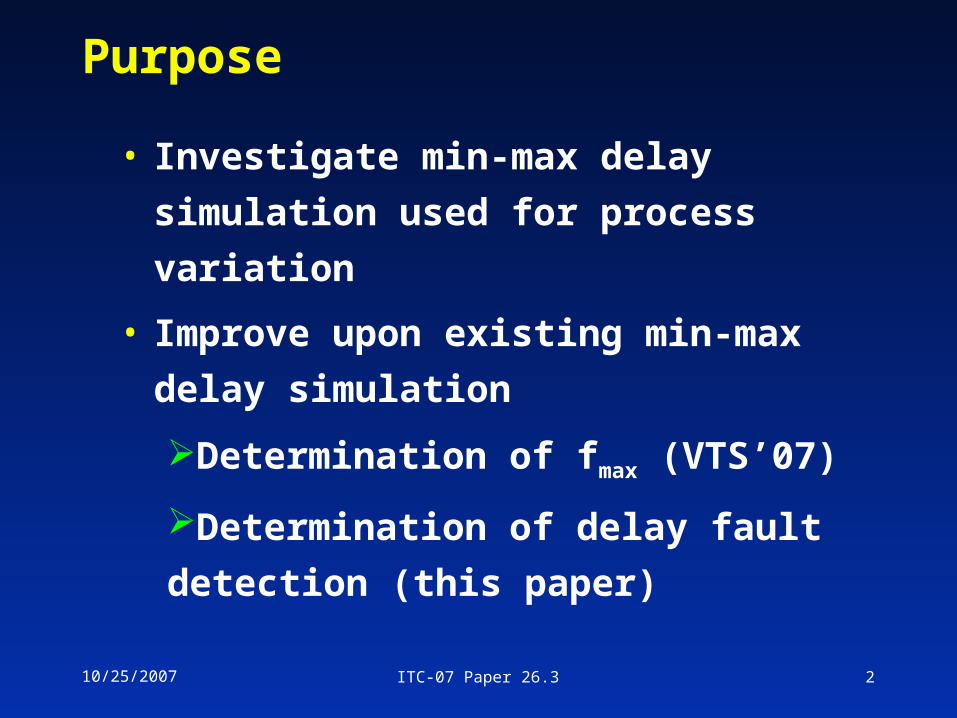
Purpose
• Investigate min-max delay simulation used
for process variation
• Improve upon existing min-max delay
simulation
Determination of fmax (VTS’07)
Determination of delay fault detection
(this paper)
10/25/2007 ITC-07 Paper 26.3 3
Outline
• Background
Min-max Delay Simulation
Determination of fmax
Hazard Lists
• Fault Detection
Correcting the detection threshold
• Finding fmax
vs Fault Detection
• Results
10/25/2007 ITC-07 Paper 26.3 4
Definitions
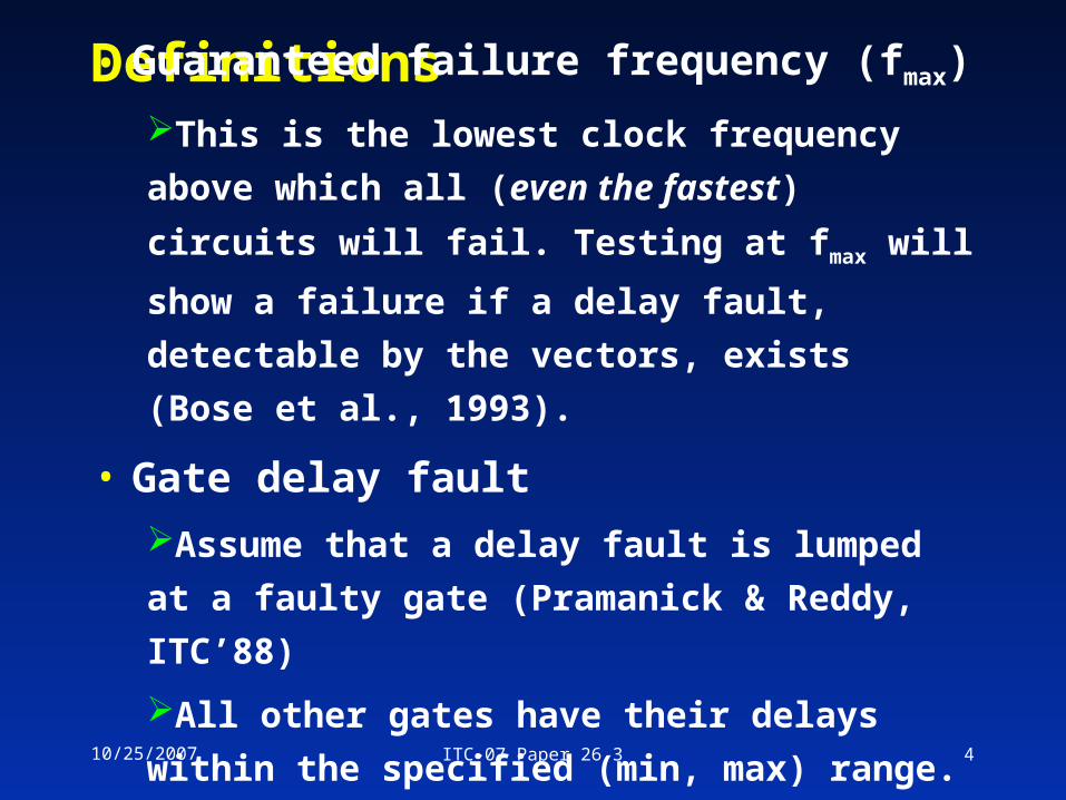
• Guaranteed failure frequency (fmax)
This is the lowest clock frequency above which
all (even the fastest) circuits will fail. Testing at
fmax will show a failure if a delay fault, detectable
by the vectors, exists (Bose et al., 1993).
• Gate delay fault
Assume that a delay fault is lumped at a faulty
gate (Pramanick & Reddy, ITC’88)
All other gates have their delays within the
specified (min, max) range.
10/25/2007 ITC-07 Paper 26.3 5
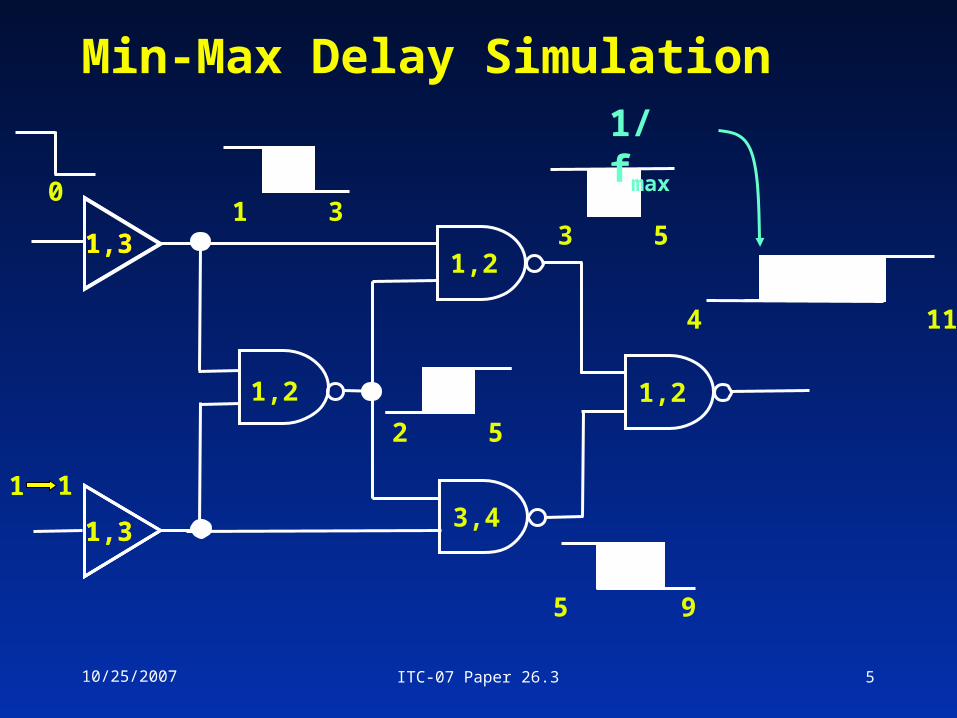
Min-Max Delay Simulation
1,31,31,3
1,31,31,3
1,2 1,2
1,2
3,4
1 3
2 5
3 5
5 9
4 11
1/fmax
0
1 1
10/25/2007 ITC-07 Paper 26.3 6
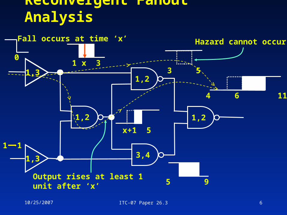
Reconvergent Fanout Analysis
1,31,31,3
1,31,31,3
1,2 1,2
1,2
3,4
1 x 33 5
5 9
4 6 11
Fall occurs at time ‘x’
x+1 5
Output rises at least 1 unit after ‘x’
Hazard cannot occur
0
1 1
10/25/2007 ITC-07 Paper 26.3 7
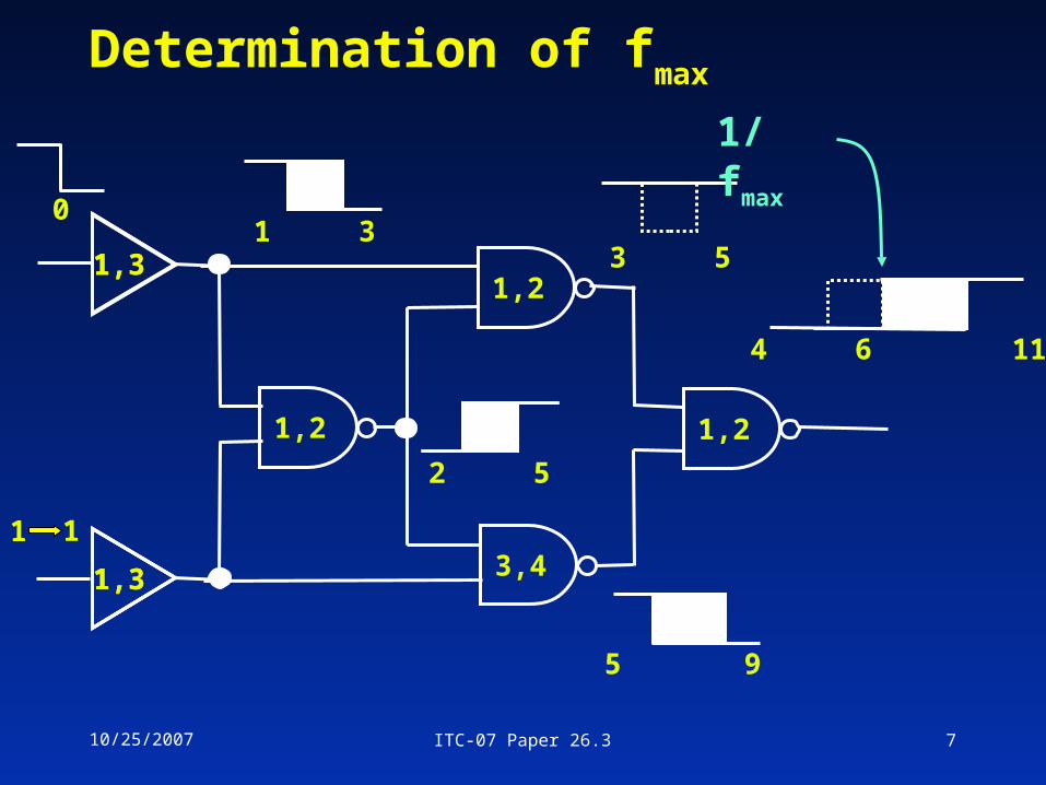
Determination of fmax
1,31,31,3
1,31,31,3
1,2 1,2
1,2
3,4
3 5
5 9
4 6 11
1 3
2 5
1/fmax
0
1 1
10/25/2007 ITC-07 Paper 26.3 8
Hazard Lists
• Hazard Lists generated at fanout points
contains
originating fanout name
ambiguity interval
• Propagate hazard lists through downcone of
fault site
similar to fault lists in concurrent fault
simulation
10/25/2007 ITC-07 Paper 26.3 9
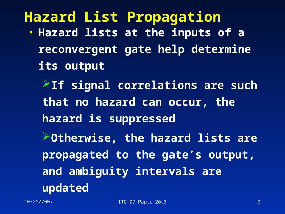
Hazard List Propagation
• Hazard lists at the inputs of a
reconvergent gate help determine its
output
If signal correlations are such that no
hazard can occur, the hazard is
suppressed
Otherwise, the hazard lists are
propagated to the gate’s output, and
ambiguity intervals are updated
10/25/2007 ITC-07 Paper 26.3 10
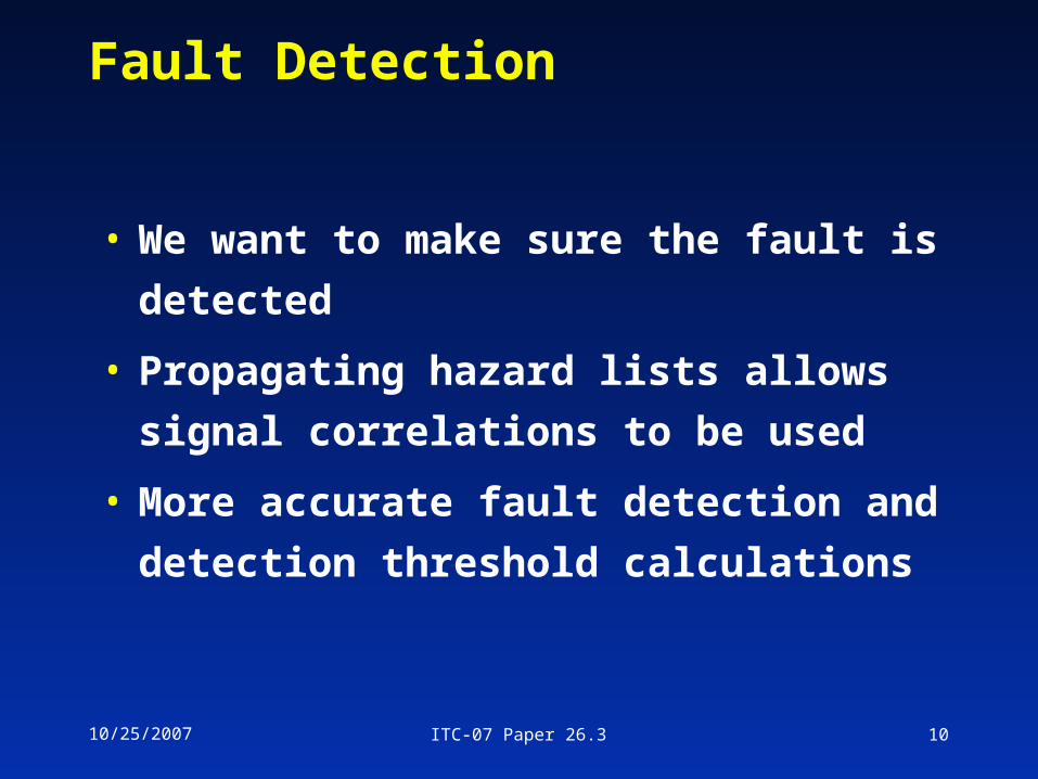
Fault Detection
• We want to make sure the fault is detected
• Propagating hazard lists allows signal
correlations to be used
• More accurate fault detection and
detection threshold calculations
10/25/2007 ITC-07 Paper 26.3 11
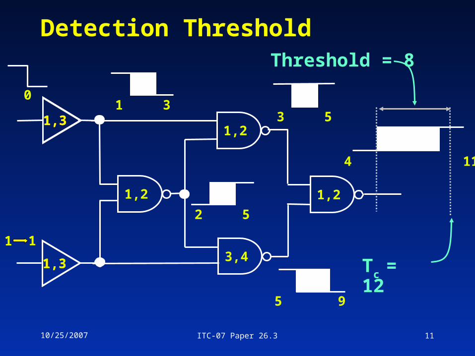
Detection Threshold
1,31,31,3
1,31,31,3
1,2 1,2
1,2
3,4
1 3
2 5
3 5
5 9
4 11
Tc = 12
Threshold = 8
0
1 1
10/25/2007 ITC-07 Paper 26.3 12
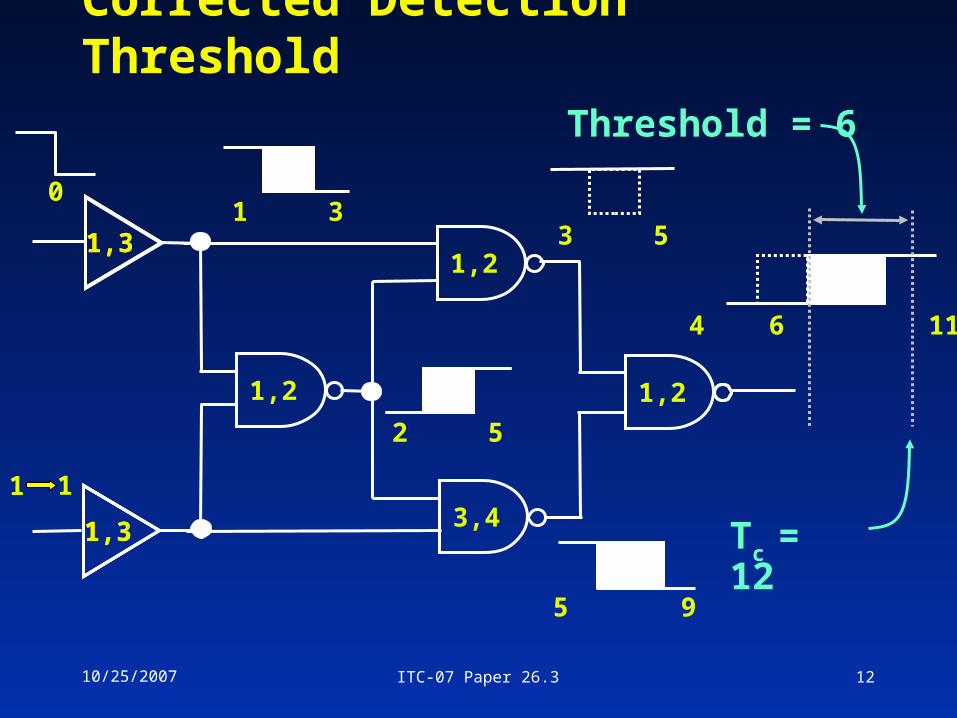
Corrected Detection Threshold
1,31,31,3
1,31,31,3
1,2 1,2
1,2
3,4
3 5
5 9
4 6 11
1 3
2 5
Tc = 12
Threshold = 6
0
1 1

10/25/2007 ITC-07 Paper 26.3 13
Finding fmax
vs Fault Detection
• A circuit output may have multiple ambiguity regions
4 6 7 10
3 4
4,6
3,40
0
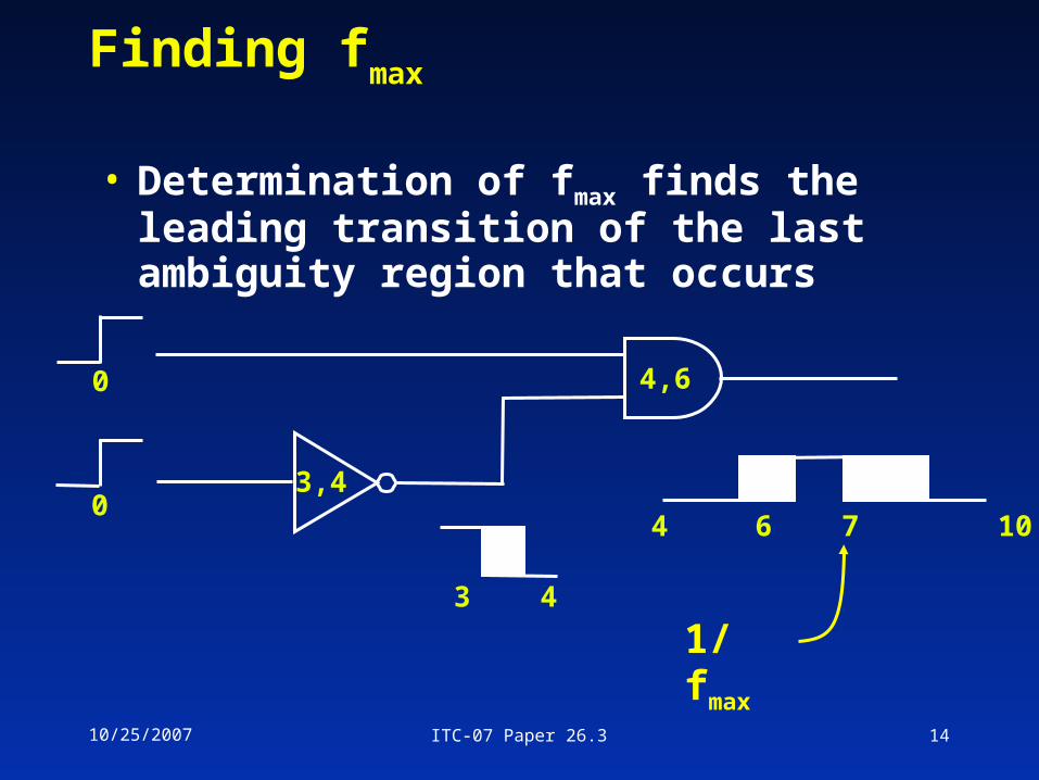
10/25/2007 ITC-07 Paper 26.3 14
Finding fmax
• Determination of fmax finds the leading transition of the last ambiguity region that occurs
4 6 7 10
3 4
4,6
3,40
0
1/fmax
10/25/2007 ITC-07 Paper 26.3 15
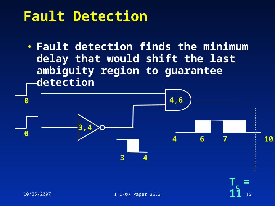
Fault Detection
• Fault detection finds the minimum delay that would shift the last ambiguity region to guarantee detection
4 6 7 10
3 4
4,6
3,40
0
Tc = 11
10/25/2007 ITC-07 Paper 26.3 16
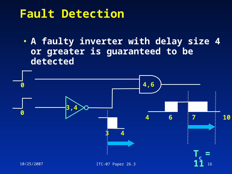
Fault Detection
• A faulty inverter with delay size 4 or greater is guaranteed to be detected
4 6 7 10
3 4
4,6
3,40
0
Tc = 11
10/25/2007 ITC-07 Paper 26.3 17
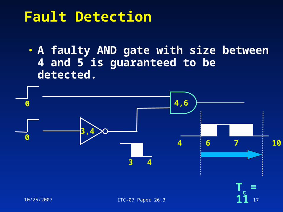
Fault Detection
• A faulty AND gate with size between 4 and 5 is guaranteed to be detected.
4 6 7 10
3 4
4,6
3,40
0
Tc = 11
10/25/2007 ITC-07 Paper 26.3 18
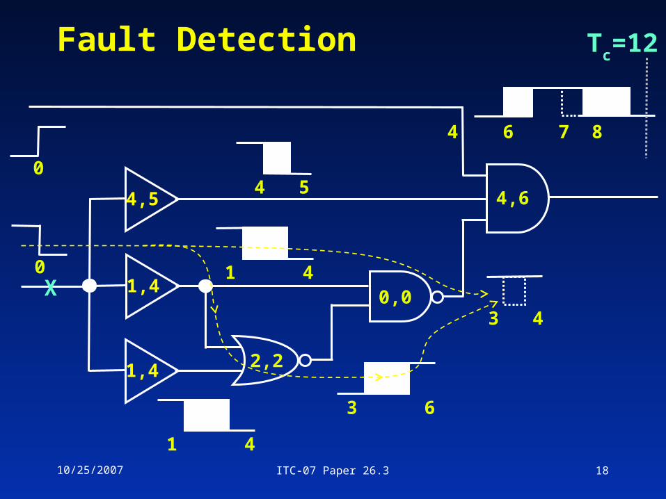
Fault Detection
4,5
1,4
1,4
0
0X 0,0
4,6
2,2
4 6 7 8 11
Tc=12
3 4
4 5
1 4
1 4
3 6
10/25/2007 ITC-07 Paper 26.3 19
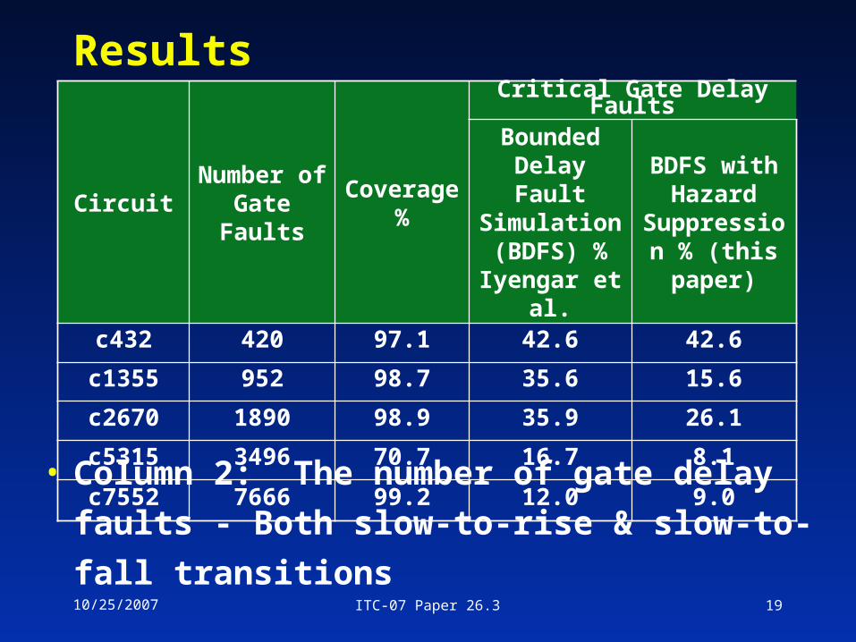
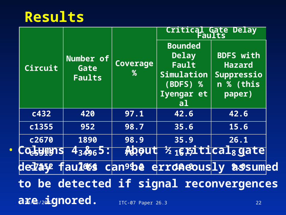
Results
CircuitNumber of Gate Faults
Coverage %
Critical Gate Delay Faults
Bounded Delay Fault Simulation (BDFS) %
Iyengar et al.
BDFS with Hazard
Suppression % (this paper)
c432 420 97.1 42.6 42.6
c1355 952 98.7 35.6 15.6
c2670 1890 98.9 35.9 26.1
c5315 3496 70.7 16.7 8.1
c7552 7666 99.2 12.0 9.0
• Column 2: The number of gate delay faults -
Both slow-to-rise & slow-to-fall transitions
10/25/2007 ITC-07 Paper 26.3 20
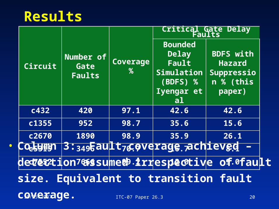
Results
CircuitNumber of Gate Faults
Coverage %
Critical Gate Delay Faults
Bounded Delay Fault Simulation (BDFS) %
Iyengar et al
BDFS with Hazard
Suppression % (this paper)
c432 420 97.1 42.6 42.6
c1355 952 98.7 35.6 15.6
c2670 1890 98.9 35.9 26.1
c5315 3496 70.7 16.7 8.1
c7552 7666 99.2 12.0 9.0
• Column 3: Fault coverage achieved – detection
assumed irrespective of fault size. Equivalent to
transition fault coverage.
10/25/2007 ITC-07 Paper 26.3 21
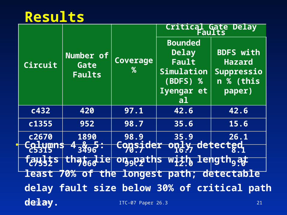
Results
CircuitNumber of Gate Faults
Coverage %
Critical Gate Delay Faults
Bounded Delay Fault Simulation (BDFS) %
Iyengar et al
BDFS with Hazard
Suppression % (this paper)
c432 420 97.1 42.6 42.6
c1355 952 98.7 35.6 15.6
c2670 1890 98.9 35.9 26.1
c5315 3496 70.7 16.7 8.1
c7552 7666 99.2 12.0 9.0
• Columns 4 & 5: Consider only detected faults that lie
on paths with length at least 70% of the longest path;
detectable delay fault size below 30% of critical path
delay.
10/25/2007 ITC-07 Paper 26.3 22
Results
CircuitNumber of Gate Faults
Coverage %
Critical Gate Delay Faults
Bounded Delay Fault Simulation (BDFS) %
Iyengar et al
BDFS with Hazard
Suppression % (this paper)
c432 420 97.1 42.6 42.6
c1355 952 98.7 35.6 15.6
c2670 1890 98.9 35.9 26.1
c5315 3496 70.7 16.7 8.1
c7552 7666 99.2 12.0 9.0
• Columns 4 & 5: About ½ critical gate delay
faults can be erroneously assumed to be
detected if signal reconvergences are ignored.
10/25/2007 ITC-07 Paper 26.3 23
Conclusion
• Conventional min-max delay simulation
produces extra hazards because correlations
between signals are neglected.
• Future work: General analysis of
reconvergent fanouts
How does this analysis affect static timing
analysis?
Timing simulation?
Dynamic timing analysis?