Embed Size (px)
Citation preview

8/7/2019 1018092- Manual- Autotrol Magnum CV
http://slidepdf.com/reader/full/1018092-manual-autotrol-magnum-cv 1/86
Installation and Service Manual
Magnum Cv Series

8/7/2019 1018092- Manual- Autotrol Magnum CV
http://slidepdf.com/reader/full/1018092-manual-autotrol-magnum-cv 2/86
8/7/2019 1018092- Manual- Autotrol Magnum CV
http://slidepdf.com/reader/full/1018092-manual-autotrol-magnum-cv 3/86
Table of Contents
Section1.0 Installation Profile Summary - - - - - - - - - - - - - - - - - - - - - - - - - - - 1
2.0 Introduction to the Magnum Cv Series - - - - - - - - - - - - - - - - - - - - - - 2
2.1 Assembling the Control to the Valve - - - - - - - - - - - - - - - - - - - - 3
2.2 General Specifications - - - - - - - - - - - - - - - - - - - - - - - - - - 7
2.3 Dimensional Specifications - - - - - - - - - - - - - - - - - - - - - - - - 8
3.0 General Installation Information - - - - - - - - - - - - - - - - - - - - - - - - - 10
3.1 Typical Installation Drawings - - - - - - - - - - - - - - - - - - - - - - - 12
4.0 Flow Diagrams - - - - - - - - - - - - - - - - - - - - - - - - - - - - - - - - 13
5.0 Control Settings - - - - - - - - - - - - - - - - - - - - - - - - - - - - - - - - 19
5.1 Manual Control - - - - - - - - - - - - - - - - - - - - - - - - - - - - - 19
5.2 Mechanical Control - - - - - - - - - - - - - - - - - - - - - - - - - - - 24
5.2.1 Common Settings - - - - - - - - - - - - - - - - - - - - - - - 245.2.2 Regenerating Iron Filter - - - - - - - - - - - - - - - - - - - - - 25
5.2.3 Backwashing Filter - - - - - - - - - - - - - - - - - - - - - - - 25
5.2.4 Salt Use Table - - - - - - - - - - - - - - - - - - - - - - - - - 26
5.2.5 Potassium Permanganate Use Table- - - - - - - - - - - - - - - 27
5.3 Impulse Controls - - - - - - - - - - - - - - - - - - - - - - - - - - - - 28
5.4 Electronic Controls- - - - - - - - - - - - - - - - - - - - - - - - - - - - 29
5.4.1 Connecting the 962 Control- - - - - - - - - - - - - - - - - - - 31
5.4.2 Connecting the 962M and the 962S Control - - - - - - - - - - - 32
5.4.3 Connecting the 962 Twin and Triple Parallel Control- - - - - - - - 33
6.0 Programming Tables for Electronic Controls - - - - - - - - - - - - - - - - - - - 34
6.1 Table I - Level I Values - - - - - - - - - - - - - - - - - - - - - - - - - - 34
6.2 Table IIA - Level II Program Values 962 Single Twin or Triple Parallel
Tank Softener or Dealkalizer - - - - - - - - - - - - - - - - - - - - - - - 35
6.3 Table IIB - Level II Program Values 962F
Single Tank Filter Mode Parameters - - - - - - - - - - - - - - - - - - - 36
6.4 Table IIC - Level II Program Values 962 Twin Tank Alternating
Softener - - - - - - - - - - - - - - - - - - - - - - - - - - - - - - - - 37
6.5 Table IID - Level II Program Values - Electronic TimeclockFilter - - - - - - - - - - - - - - - - - - - - - - - - - - - - - - - - - 38
6.6 Table IIE - Level II Program Values - Electronic Timeclock
Softener - - - - - - - - - - - - - - - - - - - - - - - - - - - - - - - 39
6.7 Explanation of Parameter Values for the 962 Single and Parallel
Tank Controls - - - - - - - - - - - - - - - - - - - - - - - - - - - - - - - - 40
6.8 New Features in the 962 Family Controls - - - - - - - - - - - - - - - - - 42
6.9 Table III Historical Data - - - - - - - - - - - - - - - - - - - - - - - - - 43
6.10 Table IV Error Messages - - - - - - - - - - - - - - - - - - - - - - - - 44
8/7/2019 1018092- Manual- Autotrol Magnum CV
http://slidepdf.com/reader/full/1018092-manual-autotrol-magnum-cv 4/86
7.0 Multi-Tank Systems - - - - - - - - - - - - - - - - - - - - - - - - - - - - - - 45
7.1 Twin Alternating - - - - - - - - - - - - - - - - - - - - - - - - - - - - - 45
7.1.1 Control Set-up - - - - - - - - - - - - - - - - - - - - - - - - - 47
7.1.2 Additional Checks - - - - - - - - - - - - - - - - - - - - - - - 48
7.2 Twin and Triple Parallel - - - - - - - - - - - - - - - - - - - - - - - - - 49
7.2.1 Control Set-up - - - - - - - - - - - - - - - - - - - - - - - - - 518.0 Start-Up Procedure - - - - - - - - - - - - - - - - - - - - - - - - - - - - - - 52
9.0 Service Instructions - - - - - - - - - - - - - - - - - - - - - - - - - - - - - - 53
10.0 Performance Data - - - - - - - - - - - - - - - - - - - - - - - - - - - - - - 55
10.1 Injector Data- - - - - - - - - - - - - - - - - - - - - - - - - - - - - - 55
10.2 Refill Control Chart (P6 Values) - - - - - - - - - - - - - - - - - - - - - 57
10.3 Injector Chart (P7 Values) - - - - - - - - - - - - - - - - - - - - - - - - 58
10.4 Drain Line Flow Control Chart - - - - - - - - - - - - - - - - - - - - - - 59
10.5 Autotrol Drain Line Flow Controls (5 gpm - 40 gpm)- - - - - - - - - - - - 60
11.0 Wiring Diagrams - - - - - - - - - - - - - - - - - - - - - - - - - - - - - - - 61
11.1 962 Series Remote Start - - - - - - - - - - - - - - - - - - - - - - - - 61
11.2 952 Impulse - - - - - - - - - - - - - - - - - - - - - - - - - - - - - - 62
11.3 952 QC Impulse - - - - - - - - - - - - - - - - - - - - - - - - - - - - 62
11.4 962 Twin and Triple Parallel - - - - - - - - - - - - - - - - - - - - - - - 63
11.5 962 Twin Alternating - - - - - - - - - - - - - - - - - - - - - - - - - - 64
12.0 Assembly Drawings and Parts Lists - - - - - - - - - - - - - - - - - - - - - - 65
12.1 942Man and 942FMan Manual Controls - - - - - - - - - - - - - - - - - 65
12.2 942 and 942F Timeclock Controls - - - - - - - - - - - - - - - - - - - - 6612.3 952,952F, and 952QC Impulse Controls - - - - - - - - - - - - - - - - - 67
12.4 962, 962F, 962TC, 962FTC, 962M, and 962S Electronic Controls - - - - - 69
12.5 Injector Assemblies - - - - - - - - - - - - - - - - - - - - - - - - - - 71
12.6 Refill Control Assemblies - - - - - - - - - - - - - - - - - - - - - - - - 72
12.7 Installation Adapters - - - - - - - - - - - - - - - - - - - - - - - - - - 73
12.8 Valve Cartridges - - - - - - - - - - - - - - - - - - - - - - - - - - - - 75
12.9 Cam and Pilot Valve Assemblies - - - - - - - - - - - - - - - - - - - - 76
12.10 Kits and Assemblies - - - - - - - - - - - - - - - - - - - - - - - - - - 79
12.11 962 Optional Switch Kits Available - - - - - - - - - - - - - - - - - - - 79

8/7/2019 1018092- Manual- Autotrol Magnum CV
http://slidepdf.com/reader/full/1018092-manual-autotrol-magnum-cv 5/861
1.0 Installation Profile Summary
Installation Date: ______________________________
Installation Location: ___________________________
Installer(s): ____________________________________
Phone Number:________________________________
Valve Number:_________________________________
Application Type: (Softener) (Filter) (Dealkalizer)
Water Source:
(Public Well) (Private Well)
(Surface Supply)
(Other)
Water Test Results:
Hardness:_______________ Iron:_______________
Other: ________________________________________
Misc:
Capacity: _______ Flow Rates:______min. ____ max.
Tank Size: Diameter ________ Height: __________
Resin or Media Volume:_________________________
Resin or Media Type: ___________________________
Brine Tank Volume:_____________________________
Salt Setting per Regeneration: ___________________
Control Valve Configuration:
Valve Type:____________________________________
(Co-current) (Countercurrent)
(Hard Water Bypass) (No Hard Water Bypass)
Refill Control:______________________________ gpm
Injector Control: ___________________________ gpm
Backwash Control:_________________________ gpm
Manual Control:
(Softener) (Filter)
Mechanical Timeclock:
(7 day) (12 day)
Salt Setting: __________________________________
Regeneration Frequency:
S M T W T F S
1 2 3 4 5 6 7 8 9 10 11 12
______________________________________________
______________________________________________
Impulse
(480) (Other) ___________________________________
Salt Setting:____________________________________
Electronic Demand Settings
P1 Time of Day _________________P2 Time of Day Regen _________________
P3 Hardness of Water _________________
P4 Salt Amount _________________
P5 Capacity of Unit _________________
P6 Refill Control Value _________________
P7 Brine Draw Value _________________
P9 Backwash Time _________________
P10 Slow Rinse Time _________________
P11 Fast Rinse Time _________________P12 Units of Measure _________________
P13 Clock Mode _________________
P14 Calendar Override _________________
P15 Reserve Type _________________
P16 Fixed Reserve Cap.
or Initial Ave. Value _________________
P17 Operation Type _________________
P18 Salt Change Lock Out _________________
P19 Flow Sensor Size _________________
P20 K-Factor or Pulse
Equivalent _________________
P21 Remote Regeneration
Switch Delay _________________
P22 Factory Use Only _________________
Twin Parallel Triple Parallel
Regeneration Type (P15): ___________
3 = Fixed Reserve withImmediate Regeneration
Fixed Reserve (P16):____________% (0% only)
Twin Alternating
Regeneration Type (P15): ___________
0 = Immediate Regen
1 = Delayed Regen
Fixed Reserve (P16): _____________%

8/7/2019 1018092- Manual- Autotrol Magnum CV
http://slidepdf.com/reader/full/1018092-manual-autotrol-magnum-cv 6/862
2.0 Introduction to the Magnum Cv Series
The Magnum CvTM Series valves offer a high degree of
installation simplicity and flexibility.
Figure 2.1 provides an overview of the major
components and connections of the 1-1/2-inch
(3.81-cm) Magnum Cv valve.
The Magnum Cv Series is available in either a
1-1/2-inch (3.81-cm) (Magnum CvTM ) or a 2-inch
(5.08-cm) (Magnum CvTM Plus) configuration.
Throughout this manual, the 1-1/2-inch (3.81-cm)
Magnum Cv is shown in illustrations where the model
type is irrelevant to what is being demonstrated.
Figure 2.1
8/7/2019 1018092- Manual- Autotrol Magnum CV
http://slidepdf.com/reader/full/1018092-manual-autotrol-magnum-cv 7/863
2.1 Assembling the Control to theMagnum Cv Series Valve
The control and the Magnum Cv series valve work
together as an integral system to ensure
synchronization. Follow the steps outlined below to
install the control on the Magnum Cv series valve.
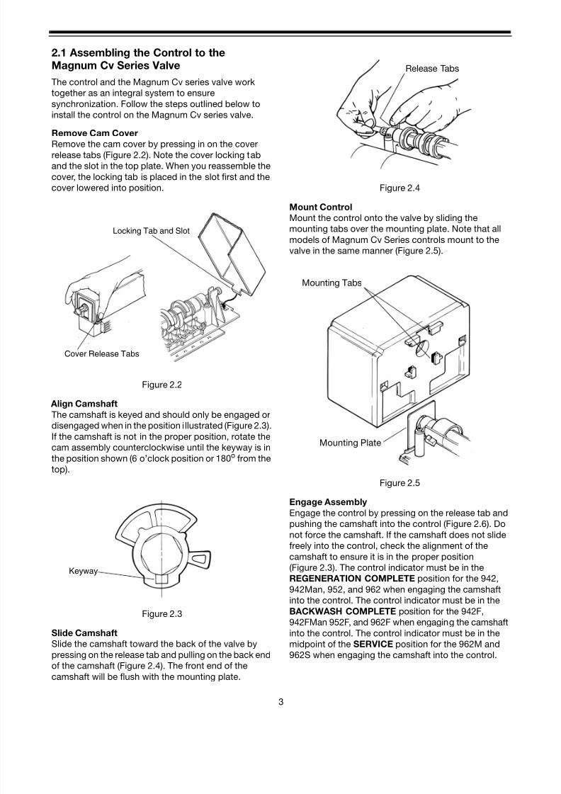
Remove Cam Cover
Remove the cam cover by pressing in on the cover
release tabs (Figure 2.2). Note the cover locking tab
and the slot in the top plate. When you reassemble the
cover, the locking tab is placed in the slot first and the
cover lowered into position.
Figure 2.2
Align Camshaft
The camshaft is keyed and should only be engaged ordisengaged when in the position illustrated (Figure 2.3).
If the camshaft is not in the proper position, rotate the
cam assembly counterclockwise until the keyway is in
the position shown (6 o’clock position or 180o from the
top).
Figure 2.3
Slide Camshaft
Slide the camshaft toward the back of the valve by
pressing on the release tab and pulling on the back end
of the camshaft (Figure 2.4). The front end of the
camshaft will be flush with the mounting plate.
Figure 2.4
Mount Control
Mount the control onto the valve by sliding the
mounting tabs over the mounting plate. Note that all
models of Magnum Cv Series controls mount to the
valve in the same manner (Figure 2.5).
Figure 2.5
Engage Assembly
Engage the control by pressing on the release tab and
pushing the camshaft into the control (Figure 2.6). Do
not force the camshaft. If the camshaft does not slide
freely into the control, check the alignment of the
camshaft to ensure it is in the proper position(Figure 2.3). The control indicator must be in the
REGENERATION COMPLETE position for the 942,
942Man, 952, and 962 when engaging the camshaft
into the control. The control indicator must be in the
BACKWASH COMPLETE position for the 942F,
942FMan 952F, and 962F when engaging the camshaft
into the control. The control indicator must be in the
midpoint of the SERVICE position for the 962M and
962S when engaging the camshaft into the control.
Cover Release Tabs
Locking Tab and Slot
Keyway
Release Tabs
Mounting Plate
Mounting Tabs

8/7/2019 1018092- Manual- Autotrol Magnum CV
http://slidepdf.com/reader/full/1018092-manual-autotrol-magnum-cv 8/864
Figure 2.6
Important:
When 942, 942Man, 952, or 962 controls are installed,
control dials must be in the REGENERATION
COMPLETE position.
When 942F, 942FMan, or 952F controls are installed,
control dials must be in the BACKWASH COMPLETE
position.
When 962M or 962S controls are installed, control dials
must be in the SERVICE position.
To disassemble the control from the valve, reverse the
assembling procedure.
Inlet, Outlet and Drain Connections
The inlet, outlet, and drain connections are designed to
accept an Osmonics supplied CPVC or brass adapter
(Figure 2.7). The adapters provide a convenient union
for the three connection ports on the valve. In addition,
they incorporate a positive O-ring face seal for ease of
installation and leak free operation. DO NOT
OVERTIGHTEN THE ADAPTERS. As a general
guideline, hand tightening the nut onto the valve will be
adequate. If additional tightening is required, never
exceed a quarter turn beyond the hand tight position.
The outlet of the 2-inch Magnum Plus has an integrated
turbine. The turbine measures the flow of water through
the outlet. This information is used by the control to
determine the best time to recycle.
Figure 2.7
No Hardwater Bypass Feature
The Magnum Cv Series control valve may be
configured for “Hard Water Bypass” or “No Hard Water
Bypass”. With Hard Water Bypass, unsoftened or
unfiltered water is allowed to bypass the Magnum Cv
Series control valve during regeneration or backwash.
With No Hard Water Bypass, a valve cartridge ensuresthat no unsoftened or unfiltered water bypasses the
valve during regeneration or backwash.
It is easy to observe which option is installed in the
valve. Note that the Hard Water Bypass End Cap has
much longer standoffs than the No Hard Water Bypass
cartridge. The No Hard Water Bypass assembly will
look identical to the other three valve cartridges on the
valve and will have a label identifying the cartridge
assembly (Figure 2.8).
Figure 2.8
Release Tab andCamshaft
Normal Standoffs
No Hard Water Bypass No Unfiltered Water Bypass
Extended Standoffs
With Hard Water Bypass End Cap
8/7/2019 1018092- Manual- Autotrol Magnum CV
http://slidepdf.com/reader/full/1018092-manual-autotrol-magnum-cv 9/865
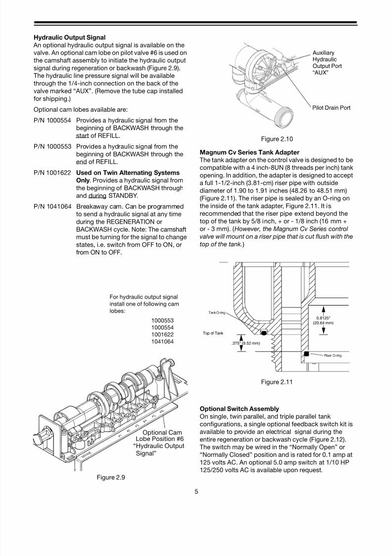
Hydraulic Output Signal
An optional hydraulic output signal is available on the
valve. An optional cam lobe on pilot valve #6 is used on
the camshaft assembly to initiate the hydraulic output
signal during regeneration or backwash (Figure 2.9).
The hydraulic line pressure signal will be available
through the 1/4-inch connection on the back of the
valve marked “AUX”. (Remove the tube cap installed
for shipping.)
Optional cam lobes available are:
P/N 1000554 Provides a hydraulic signal from the
beginning of BACKWASH through the
start of REFILL.
P/N 1000553 Provides a hydraulic signal from the
beginning of BACKWASH through the
end of REFILL.
P/N 1001622 Used on Twin Alternating Systems
Only. Provides a hydraulic signal from
the beginning of BACKWASH through
and during STANDBY.
P/N 1041064 Breakaway cam. Can be programmed
to send a hydraulic signal at any time
during the REGENERATION or
BACKWASH cycle. Note: The camshaft
must be turning for the signal to change
states, i.e. switch from OFF to ON, or
from ON to OFF.
Figure 2.9
Figure 2.10
Magnum Cv Series Tank Adapter
The tank adapter on the control valve is designed to be
compatible with a 4 inch-8UN (8 threads per inch) tank
opening. In addition, the adapter is designed to accept
a full 1-1/2-inch (3.81-cm) riser pipe with outside
diameter of 1.90 to 1.91 inches (48.26 to 48.51 mm)
(Figure 2.11). The riser pipe is sealed by an O-ring on
the inside of the tank adapter, Figure 2.11. It is
recommended that the riser pipe extend beyond the
top of the tank by 5/8 inch, + or - 1/8 inch (16 mm +
or - 3 mm). ( However, the Magnum Cv Series control
valve will mount on a riser pipe that is cut flush with the
top of the tank. )
Figure 2.11
Optional Switch Assembly
On single, twin parallel, and triple parallel tank
configurations, a single optional feedback switch kit is
available to provide an electrical signal during the
entire regeneration or backwash cycle (Figure 2.12).
The switch may be wired in the “Normally Open” or
“Normally Closed” position and is rated for 0.1 amp at
125 volts AC. An optional 5.0 amp switch at 1/10 HP
125/250 volts AC is available upon request.
Optional CamLobe Position #6
“Hydraulic Output
For hydraulic output signal
install one of following cam
lobes:
1000553
1000554
1001622
1041064
Signal”
AuxiliaryHydraulicOutput Port
Pilot Drain Port
“AUX”
.375" (9.52 mm)
0.8125"(20.64 mm)
O-ring
Top of Tank
O-ringRiser O-ring
Tank O-ring

8/7/2019 1018092- Manual- Autotrol Magnum CV
http://slidepdf.com/reader/full/1018092-manual-autotrol-magnum-cv 10/866
Figure 2.12
On ALL Magnum Cv Series tank configurations,
optional multi-switch kits are available to provide
additional electrical or switch closure signals during the
regeneration or backwash cycles. Coupled with the
optional breakaway cams, signals can be sent to
external system equipment at virtually any time while
the control/camshaft motor is running. Consult the
“Just Add Water” bulletin covering the multi-switch
option for additional application and programming
information.
Normally Closed
Normally Open
Common

8/7/2019 1018092- Manual- Autotrol Magnum CV
http://slidepdf.com/reader/full/1018092-manual-autotrol-magnum-cv 11/867
2.2 Magnum Cv Series General Specifications
Operating and Environmental
Operating Pressure ............................................................................................... 25 to 125 psig (172 to 862 kPa)
100 psig (688kPa) maximum in Canada
Operating Water Temperature Range................................................................................. 34 to 100oF (1 to 36oC)
Ambient Temperature Range.............................................................................................. 34 to 120 oF (1 to 50oC)
Cap Bolt Torque ...................................................................................................35-40 inch lbs. (3.95 to 4.51 Nm )
Connections
Inlet and Outlet................................................................................................................... 1-1/2 inch-Magnum Cv
2-inch-Magnum Cv PLUS
Tank....................................................................................................................................................... 4-inch-8UN
Brine ....................................................................................................................................................3/4-inch NPT
Pilot Drain and Auxiliary Hydraulic Out .................................................................................... 1/4-inch tube fitting
Riser Pipe Fitting .....................................................................................................................1-1/2-inch (3.81-cm)
Drain........................................................................................................................................1-1/2-inch (3.81-cm)
Physical
Dimensions..................................................................................................... Refer to drawings on pages 8 and 9
Approximate Weight (Valve and Control).................................................................................... 23.3 lbs. (10.6 kg.)
Electrical*
Voltage - 962 Series Control ..........................................................................12 VAC wall mount transformer only
Voltage - 942 Series Control ..................................................................120 VAC, 12 VAC wall mount transformer
Voltage - 952 Series Control ........................................................................................................24 VAC, 120 VAC
Power Draw........................................................................................................................................4.5 volt-amps
*See section on Electronic Controls for alternative electrical configurations.

8/7/2019 1018092- Manual- Autotrol Magnum CV
http://slidepdf.com/reader/full/1018092-manual-autotrol-magnum-cv 12/868
2.3 Magnum Cv Dimensional Specifications
1 1/2-inch Inlet, Outlet and Drain
3 . 9
9 3 ( 1 0 . 1
4 c m )
6 . 4
9 3 ( 1 6 . 5 c m )
7 . 5
0 0 ( 1 9 . 0
5 c m )
2 2 . 7
9 6 ( 5 7 . 9
0 c m )
2 . 8
1 7 ( 7 . 1
5 c m )
4 . 0
1 8 ( 1 0 . 2
0 c m )
8 . 6
8 0 ( 2 2 . 0
4 c m )
9 . 0
0 0 ( 2 2 . 8
6 c m )
1 3 . 4
8 1 ( 3 4 . 2
4 c m )
1 9 . 5
0 0 ( 4 9 . 5
3 c m )
7 . 0
0 0 ( 1 7 . 7
8 c m )
1 4 . 0
0 0 ( 3 5 . 5
6 c m )
1 5 . 5
3 9 ( 3 9 . 4
7 c
m )
1 . 1
1 3 ( 2 . 8
2 c m )
1 1 . 4
7 1 ( 2 9 . 1
3 c m )

8/7/2019 1018092- Manual- Autotrol Magnum CV
http://slidepdf.com/reader/full/1018092-manual-autotrol-magnum-cv 13/869
Magnum Cv PLUS Dimensional Specifications
2-Inch Inlet and Outlet, 1 1/2-Inch Drain
1 5 .
5 3 9
1 .
1 1 3
1 1 .
3 7 6
4 .
4 2 9
1 3 .
4 8 1
9 .
0 0 0
9 .
7 5 0
7 .
0 0 0
6 .
5 0 0
1 6 .
2 5 0
8 .
7 1 0
3 .
9 9 8
2 . 8
1 7
27.224
4.500 4.500
13.993
4.429

8/7/2019 1018092- Manual- Autotrol Magnum CV
http://slidepdf.com/reader/full/1018092-manual-autotrol-magnum-cv 14/8610
3.0 General Installation Information
Please review the following items thoroughly to ensure
an efficient and safe installation of the water treatment
system. Page 12 shows typical installation line
drawings for the Magnum Cv Series.
Operating Conditions - A minimum dynamic
operating water pressure of 25 psig (172 kPa) is required for the Magnum Cv Series control valve to operate properly. Water pressure is not to
exceed 125 psig (862 kPa). In Canada, water pressure
is not to exceed 100 psig (688 kPa). Water temperature
is not to exceed 100oF (36oC). Do not subject the valve
to freezing conditions.
Space Requirements - Allow adequate space for the
water treatment system and associated piping. The
General Specifications section (pages 7-9) provides
the overall dimensions of the control valve as well as
the dimensional reference information for each of the
connection ports. A minimum of 4 1/2 inches (11.5 cm)
front and rear clearance is required for cartridgeassembly and removal.
Plumbing - Always follow good plumbing practices
and conform to local codes. Check existing pipes for
lime and/or iron buildup. Replace piping if heavy
buildup exists and initiate the proper treatment to
prevent additional occurrences. Locate the equipment
close to a drain that is capable of handling the
maximum drain flow rate during backwash.
Flexible Connectors - Some tanks expand and
contract over the acceptable range of operating water
pressures of the Magnum Cv Series control valve. The
use of flexible connectors is recommended on
polywound or fiberglass tank installations of 24-inch
(60.96-cm) diameter and larger.
Inlet and Outlet Piping - Inlet and outlet plumbing
should be adequately supported to avoid excessive
loads on the valve. Install a manual bypass system to
provide for occasions when the water conditioner must
be bypassed for servicing.
Drain LIne Piping - To prevent mineral loss during
backwash, and to ensure proper operation of the
Magnum Cv Series control valve, A DRAIN LINE
FLOW CONTROL must be plumbed into the drain line
prior to placing the valve in the service mode. Flow
controls from 5 to 40 gpm (18.92 to 151.4 Lpm) are
available from Osmonics and can be easily installed in
the drain line (Figure 3.1). Flow controls greater than 40
gpm (151.4 Lpm) must be plumbed externally.
Selection of the proper drain line flow control will
depend on the tank size and media used for the
installation. See Table 10.3 on page 55.
The following general drain line piping guidelines
should be observed:
• 1 inch (2.54 cm) or larger piping
• Should not exceed 20 feet (6.1 m)
• Should not be elevated higher than the control
valve
• No shut-off valves should be installed in drain line
• Minimal number of elbows and fittings should be
installed in drain line
• Piping must be self-supporting
• Install air gap to provide a siphon break
• Flow control should be installed as close to the
Magnum Cv Series control valve as possible if an
external flow control is used
Figure 3.1
Brining System - The Magnum Cv Series control
valve utilizes timed water refill to add water to the salt
tank. A refill tube with check ball is required in the brine
tank that will not restrict the refill or brine draw flow rate
capabilities of the valve. Although not required, a
separate brine valve (safety float) system is
recommended for use with Magnum Cv Series
installations. Select a “High-Flow” brine valve that will
not restrict the refill or brine draw flow rate capabilities
of the valve. The “Performance Data and Charts”
section (Section 10.0) of this manual contains flow rate
information for various size injectors and refillcontrollers.
Pilot Drain - During regeneration, a small amount of
water (200 ml or 1 cup) is discharged from the 1/4-inch
(6.3-mm) tube fitting on the back of the valve marked
DRAIN (Figure 3.2). To prevent this water from being
discharged to the floor, plumb this connection to a non-
pressurized drain or to the brine tank. Do not plug or
apply back pressure to the pilot drain at any time.
Crimping the pilot drain line or installing the line to go
up, which causes backpressure, will prevent the
Drain Line Flow Control Disk

8/7/2019 1018092- Manual- Autotrol Magnum CV
http://slidepdf.com/reader/full/1018092-manual-autotrol-magnum-cv 15/8611
diaphragm cartridges from shifting properly through
the cycles of regeneration or backwash.
Figure 3.2
Electrical
1. Electrical requirements for the installation willdepend on the configuration of the control.
2. The standard North American Series 962 electronic
control is supplied with a 12 volt wall mount
transformer. Optional wall mount transformers are
available in the following configurations: Japanese
plug @ 100 volts/50 or 60 Hz, Australian/Argentine
plug @ 240 volts/50 Hz, British plug @ 240 volts/50
Hz, European/Italian plug @ 230 volts/50 Hz.
Optional transformers must be ordered separately
for all international 12 VAC configurations.
3. The standard North American Series 952 impulse
controls use 120 VAC or 24 VAC/50 or 60 Hz power.
Auxiliary HydraulicOutput Port - Plugged
Pilot Drain Port

8/7/2019 1018092- Manual- Autotrol Magnum CV
http://slidepdf.com/reader/full/1018092-manual-autotrol-magnum-cv 16/8612
3.1 Typical Installation Drawings
Figure 3.3 Magnum Cv and Cv Plus, Single Tank Softener Units with 962 Electronic Control
Inlet Valve
Drain
962 Control
1.5” Riser Tube
Hub & Lateral
Brine Tank
Brine Line
Turbine (standardwith 962 Control)
Outlet Valve
Manual Bypass ValveDrain Line Flow Control
Note: Support Inlet andOutlet PipingAdequately.
(Required)
Magnum Cv
Magnum Cv Plus
8/7/2019 1018092- Manual- Autotrol Magnum CV
http://slidepdf.com/reader/full/1018092-manual-autotrol-magnum-cv 17/8613
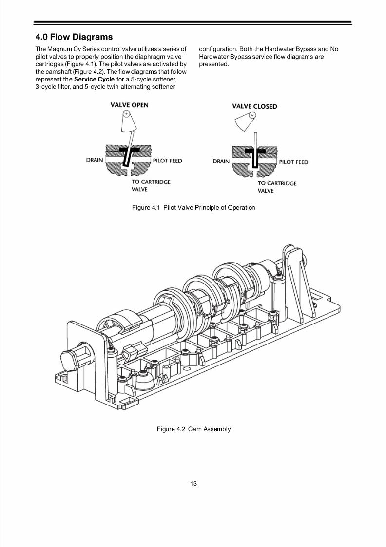
4.0 Flow Diagrams
The Magnum Cv Series control valve utilizes a series of
pilot valves to properly position the diaphragm valve
cartridges (Figure 4.1). The pilot valves are activated by
the camshaft (Figure 4.2). The flow diagrams that follow
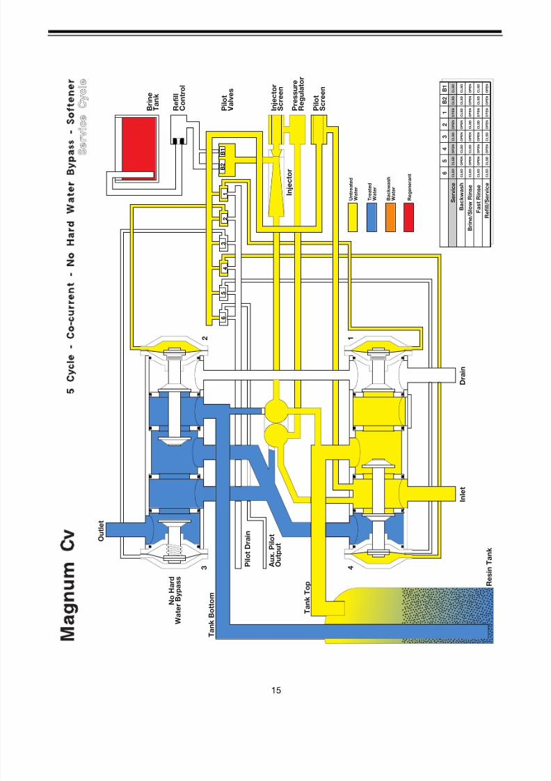
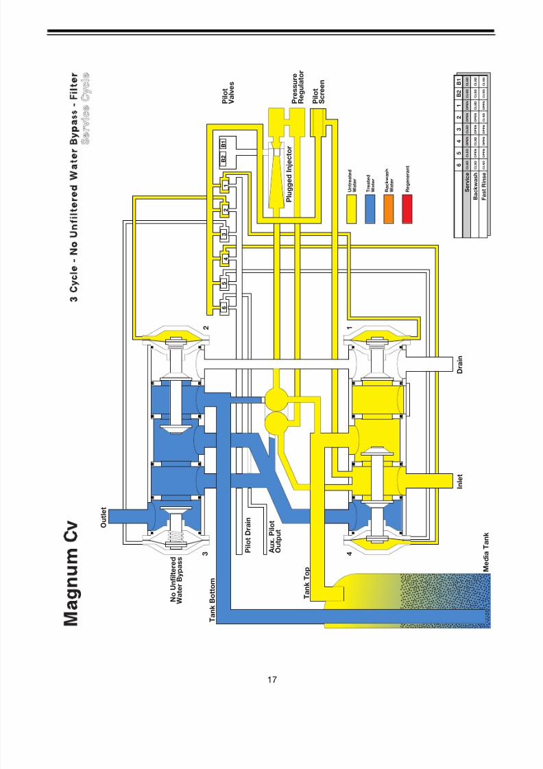
represent the Service Cycle for a 5-cycle softener,
3-cycle filter, and 5-cycle twin alternating softener
configuration. Both the Hardwater Bypass and No
Hardwater Bypass service flow diagrams are
presented.
Figure 4.1 Pilot Valve Principle of Operation
Figure 4.2 Cam Assembly

8/7/2019 1018092- Manual- Autotrol Magnum CV
http://slidepdf.com/reader/full/1018092-manual-autotrol-magnum-cv 18/86
8/7/2019 1018092- Manual- Autotrol Magnum CV
http://slidepdf.com/reader/full/1018092-manual-autotrol-magnum-cv 19/8615
B 1
B 2
1
2
3
4
5
6
P r e s s u r e
R e g u l a t o r
P i l o t
S c r e e n
R e f i l l
C o n t r o l
B r i n e
T a n k
U n t r e a t e d
W a t e r
T r e a t e d
W a t e r
I n j e c t o r
P i l o t
V a l v e s
I n l e t
T a n k T o p
D r a i n
1
T a n k B o t t o m
O u t l e t
2
B a c k w a s h
W a t e r
R e g e n e r a n t
A u x . P
i l o t
O u t p u t
I n j e c t o r
S c r e e n
R e s i n T a n k
4 3 P i l o t D
r a i n
N o H a r d
W a t e r B y p a s s
6
5
4
3
2
1
B 2
B 1
S e r v i c e
B a c k w a s h
B r i n e / S l o w R i n s e
F a s t R i n s e
R e f i l l / S e r v i c e
O P E N
O P E N
O P E N
C L S D
C L S D
C L S D
C L S
D
O P E N
O P E N
C L S D
C L S D
O P E N
C L S D
C L S D
O P E N
O P E N
C L S D
C L S D
O P E N
O P E N
O P E N
C L S D
C L S D
O P E N
O P E N
O P E N
O P E N
C L S D
O P E N
O P E N
C L S D
O P E N
O P E N
O P E N
C L S D
C L S D
C L S D
C L S D
C L S D
C L S
D

8/7/2019 1018092- Manual- Autotrol Magnum CV
http://slidepdf.com/reader/full/1018092-manual-autotrol-magnum-cv 20/8616
B 1
B 2
1
2
3
4
5
6
P r e s s u r e
R e g u l a t o r
P i l o t
S c r e e n
U n t r e a t e d
W a t e r
T r e a t e d
W a t e r
P l u g g e d I n j e c t o r
P i l o t
V a l v e s
I n l e t
T a n k T o p
D r a i n
1
T a n k B o t t o m
O u t l e t
2
B a c k w a s h
W a t e r
R e g e n e r a n t
A u x .
P i l o t
O u t p
u t
M e d i a T a n
k
4 3 P i l o t
D r a i n
U n f i l t e r e d
W a t e r B y p a s s
6
5
4
3
2
1
B 2
B 1
S e r v i c e
B a c k w a s h
F a s t R i n s e
O P E N
O P E N
O P E N
C L S D
C L S D
C L S D
C L S D
O P E N
O P E N
C L S D
C L S D
O P E N
C L S D
C L S D
C L S D
C L S D
O P E N
O P E N
O P E N
O P E N
C L S D
C L S D
C L S D
C L S D
8/7/2019 1018092- Manual- Autotrol Magnum CV
http://slidepdf.com/reader/full/1018092-manual-autotrol-magnum-cv 21/8617
B 1
B 2
1
2
3
4
5
6
P r e s s u r e
R e g u l a t o r
P i l o t
S c r e e n
U n t r e a t e d
W a t e r
T r e a t e d
W a t e r
P l u g g e d I n j e c t o r
P i l o t
V a l v e s
I n l e t
T a n k T o p
D r a i n
1
T a n k B o t t o m
O u t l e t
2
B a c k w a s h
W a t e r
R e g e n e r a n t
A u x .
P i l o t
O u t p
u t
M e d i a T a n
k
4 3 P i l o t
D r a i n
N o U n f i l t e r e d
W a t e r B y p a s s
6
5
4
3
2
1
B 2
B 1
S e r v i c e
B a c k w a s h
F a s t R i n s e
O P E N
O P E N
O P E N
C L S D
C L S D
C L S D
C L S D
O P E N
O P E N
C L S D
C L S D
O P E N
C L S D
C L S D
C L S D
C L S D
O P E N
O P E N
O P E N
O P E N
C L S D
C L S D
C L S D
C L S D

8/7/2019 1018092- Manual- Autotrol Magnum CV
http://slidepdf.com/reader/full/1018092-manual-autotrol-magnum-cv 22/8618
B 1
B 2
1
2
3
4
5
6
P r e s s u r e
R e g u l a t o r
P i l o t
S c r e e n
R e f i l l
C o n t r o l
B r i n e
T a n k
U n t r e a t e d
W a t e r
T r e a t e d
W a t e r
I n j e c t o r
P i l o t
V a l v e s
I n l e t
T a n k T o p
D r a i n
1
T a n k B o t t o m
O u t l e t
2
B a c k w a s h
W a t e r
R e g e n e r a n t
A u x . P i l o t
O u t p u t
I n j e c t o r
S c r e e n
R e s i n T a n
k
4 3 P i l o t D r a i n
N o H a r d
W a t e r B y p a s s
6
5
4
3
2
1
B 2
B 1
S e r v i c e
F i r s t S t a n d b y
B a c k w a s h
B r i n e / S l o w R i n s e
F a s t R i n s e
R e f i l l
S e c o n d S t a n d b y
O P E N
O P E N
O P E N
C L S D
C L S D
C L S D
C L S D
O P E N
O P E N
O P E N
C L S D
C L S D
C L S D
O P E N
O P E N
O P E N
C L S D
C L S D
O P E N
C L S D
C L S D
O P E N
O P E N
C L S D
C L S D
O P E N
O P E N
O P E N
C L S D
C L S D
O P E N
O P E N
O P E N
O P E N
C L S D
O P E N
O P E N
C L S D
C L S D
O P E N
O P E N
C L S D
O P E N
O P E N
O P E N
C L S D
O P E N
O P E N
O P E N
C L S D
C L S D
C L S D
C L S D
C L S D
C L S D
C L S D

8/7/2019 1018092- Manual- Autotrol Magnum CV
http://slidepdf.com/reader/full/1018092-manual-autotrol-magnum-cv 23/8619
5.0 Control Settings
5.1 Manual
Series 942Man Controls
The 942Man represents the maximum in versatility and
ease of operation for the manual control valve system.
Upgrade to an automatic system is easily
accomplished by switching the manual control to aclock or demand control.
DO NOT TURN THE INDICATOR KNOB CLOCKWISE
AT ANY TIME.
Regeneration Instructions
1. Move indicator knob COUNTERCLOCKWISE from
the Regeneration Complete position to the center
of the Backwash (Figure 5.1) position. DO NOT turn
the knob clockwise.
Figure 5.1
2. The indicator knob should remain in the Backwash
position for the appropriate amount of time.
Specific backwash times are determined by the
inlet water quality (i.e.: the amount of iron,
manganese, turbidity), the amount of time between
regenerations, water pressure, and flow. The
typical backwash time is 10-15 minutes*. The unit
should be in backwash until water at the drain is
clear.
3. When the backwash is complete, move theindicator knob COUNTERCLOCKWISE to the
center of the Brine/Slow Rinse position
(Figure 5.2). See the “Suggested Brine Draw/Slow
Rinse Table” to determine the correct draw/rinse
time. Please note that the tables are given at three
salting levels and four pressures. The indicator
knob should remain in the Brine/Slow Rinse
position for the time* indicated in the table.
Figure 5.2
4. When the slow rinse is complete, move the
indicator knob COUNTERCLOCKWISE to the
center of the Fast Rinse position (Figure 5.3). The
indicator knob should remain in the Fast Rinse
position for the appropriate amount of time.
specific fast rinse times are determined by water
quality, clarity of drain water, water pressure, and
flow. Fast rinse serves to eliminate excess salt and
repack the resin bed for the service run. Typically
fast rinse should continue for 5 - 15 minutes*.
Important: If excessive fast rinse time is required to
return the service effluent to quality, there could be an
underlying cause, such as low pressure, fouled resin
bed, fouled injector, etc.
Figure 5.3
5. When the fast rinse is complete, move the indicator
knob COUNTERCLOCKWISE to the Refill position
(Figure 5.4). Determine the correct refill time* from
Table 5.1 below. The indicator knob should remain
in the Refill position for the time indicated in the
table.
*Note: The times given are only general guidelines.
Adjustment of the times may be necessary for specific
applications and conditions.

8/7/2019 1018092- Manual- Autotrol Magnum CV
http://slidepdf.com/reader/full/1018092-manual-autotrol-magnum-cv 24/8620
Figure 5.4
6. When the refill is complete move the indicator knob
COUNTERCLOCKWISE to the Regeneration
Complete position (Figure 5.5). The unit will now
provide softened water.
Figure 5.5
*Note: The times given are only general guidelines.
Adjustment of the times may be necessary for specific
applications and conditions.
Regenerating Iron Filters - Model 942Man
Refer to Regenerating Iron Filters Model 942 in
Section 5.2 for information on this type of system
application. All common control settings, control
regenerant settings, and regenerant usage which apply
to the 942Man control are the same as those used on
the 942 control.
When using the 942Man control however, the time of
each cycle cannot be predicted exactly. Note the
following regeneration cycle parameters:
• Backwash the filter until the drain water flows clear,
typically 5 - 15 minutes.
• Regenerant draw continues until the check ball
closes to end draw.
• Slow Rinse should continue until there is NO pinkcolor to the drain water flow. This is typically four
times that of the regenerant draw time.
• Fast Rinse time continues until there is no pink
color to the drain water flow, typically 5 - 15
minutes.
• Refill time is determined by the size of the refill flow
control and the amount of regenerant required for a
particular size system. Refer to Regenerant Use
Table in Section 5.2.
Table 5.1 Suggested Refill Times
Tank
Diameter
Resin
cu.ft.Refill PN
Refill Flow Rategpm (lpm)
@ 60 psig
(414 kPa)
Minimum Salting
(6 lbs/ft3)
(96.1 kg/m3
)
Medium Salting
(10 lbs/ft3)
( 160.18 kg/m3
)
Maximum
Salting (15 lb/ft3)
(240.27 kg/m3
)
14 in (35.5 cm) 3 1040679 0.7 (2.6 lpm) 9 minutes 15 minutes 22 minutes
16 in (40.6 cm) 4 1040680 0.8 (3 lpm) 10 minutes 17 minutes 25 minutes
18 in (45.7 cm) 5 1040681 1.0 (3.8 lpm) 10 minutes 17 minutes 25 minutes
21 in (53.5 cm) 7 1040682 1.4 (5.31 lpm) 10 minutes 17 minutes 25 minutes
24 in (60.9 cm) 10 1040683 2.0 (7.6 lpm) 10 minutes 17 minutes 25 minutes
30 in (76.2 cm) 15 1040684 3.0 (11.4 lpm) 10 minutes 17 minutes 25 minutes
36 in (91.4 cm) 20 1040685 5.0 (18.9 lpm) 8 minutes 14 minutes 20 minutes
8/7/2019 1018092- Manual- Autotrol Magnum CV
http://slidepdf.com/reader/full/1018092-manual-autotrol-magnum-cv 25/8621
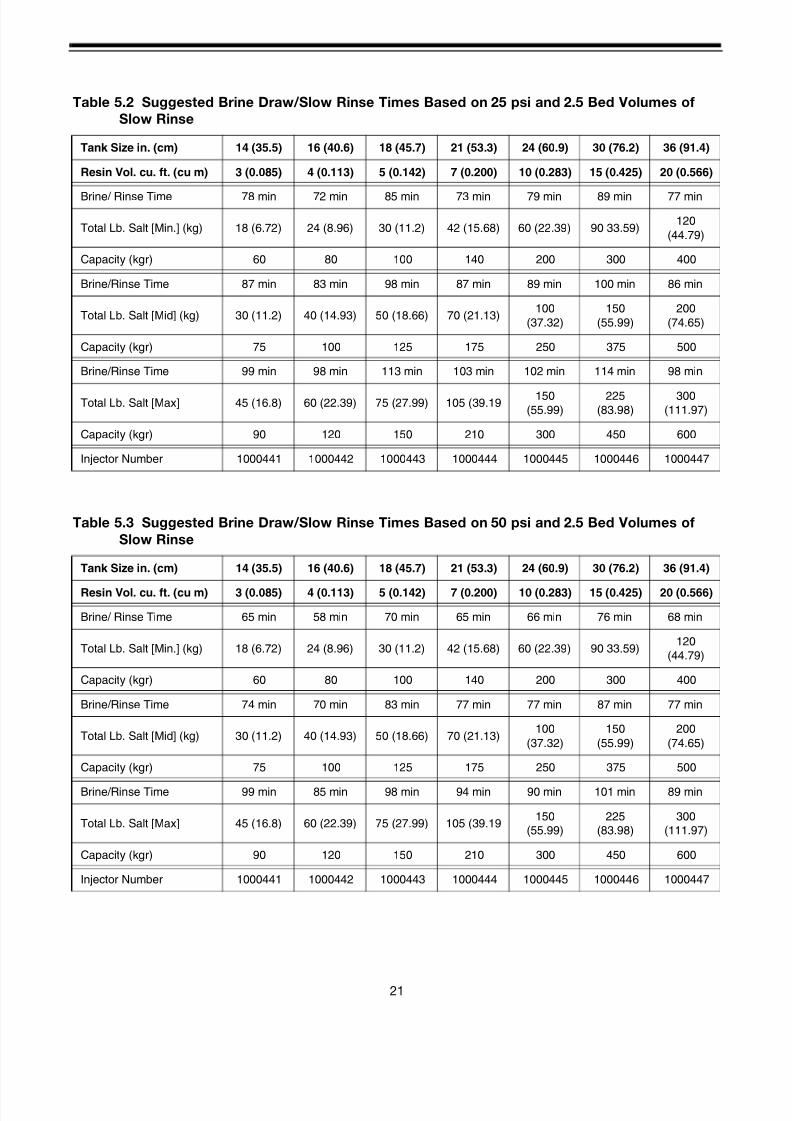
Table 5.2 Suggested Brine Draw/Slow Rinse Times Based on 25 psi and 2.5 Bed Volumes of
Slow Rinse
Tank Size in. (cm) 14 (35.5) 16 (40.6) 18 (45.7) 21 (53.3) 24 (60.9) 30 (76.2) 36 (91.4)
Resin Vol. cu. ft. (cu m) 3 (0.085) 4 (0.113) 5 (0.142) 7 (0.200) 10 (0.283) 15 (0.425) 20 (0.566)
Brine/ Rinse Time 78 min 72 min 85 min 73 min 79 min 89 min 77 min
Total Lb. Salt [Min.] (kg) 18 (6.72) 24 (8.96) 30 (11.2) 42 (15.68) 60 (22.39) 90 33.59)120
(44.79)
Capacity (kgr) 60 80 100 140 200 300 400
Brine/Rinse Time 87 min 83 min 98 min 87 min 89 min 100 min 86 min
Total Lb. Salt [Mid] (kg) 30 (11.2) 40 (14.93) 50 (18.66) 70 (21.13)100
(37.32)
150
(55.99)
200
(74.65)
Capacity (kgr) 75 100 125 175 250 375 500
Brine/Rinse Time 99 min 98 min 113 min 103 min 102 min 114 min 98 min
Total Lb. Salt [Max] 45 (16.8) 60 (22.39) 75 (27.99) 105 (39.19 150(55.99)
225(83.98)
300(111.97)
Capacity (kgr) 90 120 150 210 300 450 600
Injector Number 1000441 1000442 1000443 1000444 1000445 1000446 1000447
Table 5.3 Suggested Brine Draw/Slow Rinse Times Based on 50 psi and 2.5 Bed Volumes of
Slow Rinse
Tank Size in. (cm) 14 (35.5) 16 (40.6) 18 (45.7) 21 (53.3) 24 (60.9) 30 (76.2) 36 (91.4)
Resin Vol. cu. ft. (cu m) 3 (0.085) 4 (0.113) 5 (0.142) 7 (0.200) 10 (0.283) 15 (0.425) 20 (0.566)
Brine/ Rinse Time 65 min 58 min 70 min 65 min 66 min 76 min 68 min
Total Lb. Salt [Min.] (kg) 18 (6.72) 24 (8.96) 30 (11.2) 42 (15.68) 60 (22.39) 90 33.59)120
(44.79)
Capacity (kgr) 60 80 100 140 200 300 400
Brine/Rinse Time 74 min 70 min 83 min 77 min 77 min 87 min 77 min
Total Lb. Salt [Mid] (kg) 30 (11.2) 40 (14.93) 50 (18.66) 70 (21.13)100
(37.32)
150
(55.99)
200
(74.65)
Capacity (kgr) 75 100 125 175 250 375 500
Brine/Rinse Time 99 min 85 min 98 min 94 min 90 min 101 min 89 min
Total Lb. Salt [Max] 45 (16.8) 60 (22.39) 75 (27.99) 105 (39.19150
(55.99)
225
(83.98)
300
(111.97)
Capacity (kgr) 90 120 150 210 300 450 600
Injector Number 1000441 1000442 1000443 1000444 1000445 1000446 1000447
8/7/2019 1018092- Manual- Autotrol Magnum CV
http://slidepdf.com/reader/full/1018092-manual-autotrol-magnum-cv 26/8622
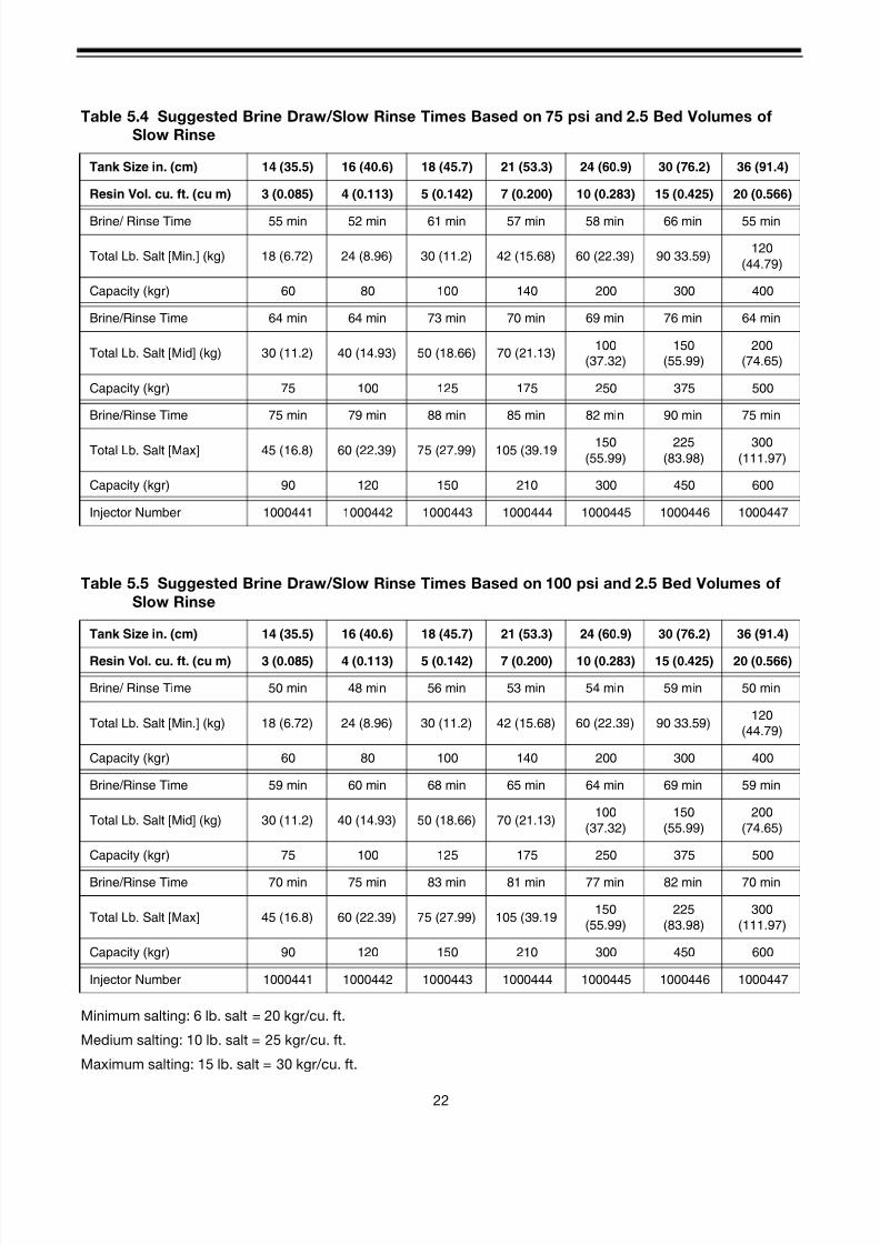
Minimum salting: 6 lb. salt = 20 kgr/cu. ft.
Medium salting: 10 lb. salt = 25 kgr/cu. ft.
Maximum salting: 15 lb. salt = 30 kgr/cu. ft.
Table 5.4 Suggested Brine Draw/Slow Rinse Times Based on 75 psi and 2.5 Bed Volumes of
Slow Rinse
Tank Size in. (cm) 14 (35.5) 16 (40.6) 18 (45.7) 21 (53.3) 24 (60.9) 30 (76.2) 36 (91.4)
Resin Vol. cu. ft. (cu m) 3 (0.085) 4 (0.113) 5 (0.142) 7 (0.200) 10 (0.283) 15 (0.425) 20 (0.566)
Brine/ Rinse Time 55 min 52 min 61 min 57 min 58 min 66 min 55 min
Total Lb. Salt [Min.] (kg) 18 (6.72) 24 (8.96) 30 (11.2) 42 (15.68) 60 (22.39) 90 33.59)120
(44.79)
Capacity (kgr) 60 80 100 140 200 300 400
Brine/Rinse Time 64 min 64 min 73 min 70 min 69 min 76 min 64 min
Total Lb. Salt [Mid] (kg) 30 (11.2) 40 (14.93) 50 (18.66) 70 (21.13)100
(37.32)
150
(55.99)
200
(74.65)
Capacity (kgr) 75 100 125 175 250 375 500
Brine/Rinse Time 75 min 79 min 88 min 85 min 82 min 90 min 75 min
Total Lb. Salt [Max] 45 (16.8) 60 (22.39) 75 (27.99) 105 (39.19150
(55.99)
225
(83.98)
300
(111.97)
Capacity (kgr) 90 120 150 210 300 450 600
Injector Number 1000441 1000442 1000443 1000444 1000445 1000446 1000447
Table 5.5 Suggested Brine Draw/Slow Rinse Times Based on 100 psi and 2.5 Bed Volumes of
Slow Rinse
Tank Size in. (cm) 14 (35.5) 16 (40.6) 18 (45.7) 21 (53.3) 24 (60.9) 30 (76.2) 36 (91.4)
Resin Vol. cu. ft. (cu m) 3 (0.085) 4 (0.113) 5 (0.142) 7 (0.200) 10 (0.283) 15 (0.425) 20 (0.566)
Brine/ Rinse Time 50 min 48 min 56 min 53 min 54 min 59 min 50 min
Total Lb. Salt [Min.] (kg) 18 (6.72) 24 (8.96) 30 (11.2) 42 (15.68) 60 (22.39) 90 33.59)120
(44.79)
Capacity (kgr) 60 80 100 140 200 300 400
Brine/Rinse Time 59 min 60 min 68 min 65 min 64 min 69 min 59 min
Total Lb. Salt [Mid] (kg) 30 (11.2) 40 (14.93) 50 (18.66) 70 (21.13)100
(37.32)
150
(55.99)
200
(74.65)
Capacity (kgr) 75 100 125 175 250 375 500
Brine/Rinse Time 70 min 75 min 83 min 81 min 77 min 82 min 70 min
Total Lb. Salt [Max] 45 (16.8) 60 (22.39) 75 (27.99) 105 (39.19150
(55.99)
225
(83.98)
300
(111.97)
Capacity (kgr) 90 120 150 210 300 450 600
Injector Number 1000441 1000442 1000443 1000444 1000445 1000446 1000447

8/7/2019 1018092- Manual- Autotrol Magnum CV
http://slidepdf.com/reader/full/1018092-manual-autotrol-magnum-cv 27/8623
942FMan - Manual Filter Control for the Magnum
Cv Valve
The 942FMan represents the maximum in versatility
and ease of operation for the manual control valve
system. Upgrade to an automatic system is easily
accomplished by switching the manual control to a
clock or demand control.
DO NOT TURN THE INDICATOR KNOB CLOCKWISE
AT ANY TIME.
Backwash Instructions:
1. Move the indicator knob COUNTERCLOCKWISE
from the Backwash Complete position to the
center of the Backwash (Figure 5.6) position. DO
NOT turn the knob clockwise. The knob should
remain in the Backwash position for 5 to 20
minutes*, or until the water runs clear at the drain.
Figure 5.6
2. When the backwash is finished, move the indicator
knob COUNTERCLOCKWISE to the center of the
Fast Rinse position (Figure 5.7). The knob should
remain in the Fast Rinse position for 5 to 20
minutes*, or until the water runs clear at the drain.
Figure 5.7
3. After the fast rinse is complete, return the filter to
service by rotating the indicator knob
COUNTERCLOCKWISE to the Backwash
Complete position (Figure 5.8).
Figure 5.8
*Note: the times given are only general guidelines.
Adjustment of the times may be necessary for specific
applications and conditions.

8/7/2019 1018092- Manual- Autotrol Magnum CV
http://slidepdf.com/reader/full/1018092-manual-autotrol-magnum-cv 28/8624
5.2 Mechanical
Series 942 Mechanical Controls
The Series 942 mechanical controls provide
mechanical timeclock function for water softening and
filter applications; 942 model for softening
applications, (Figure 5.9) 942F model for filtering
applications. Identification of the specific model is
provided on the front of the control. The controls arevery similar in appearance, function, and settings.
However, they require different gear drives and
camshafts to function properly. The softener and filter
camshafts are identified in the Assembly Drawings
and Parts List section of this manual (page 72).
Figure 5.9
5.2.1 Common Settings
Setting the Time of Day, the Days of Regeneration or
Backwash and performing manual regenerations or
backwashing are the same for 942 and 942F controls.
Setting the Time of Day
Rotate the Clock Dial clockwise until the pointer
indicates the correct time of day. With the time of day
set, the conditioner will regenerate at approximately2:00 a.m. If it is desired to have the unit regenerate at
an earlier or later time, simply offset the current time of
day accordingly. For example, to have the unit
regenerate at 4:00 a.m., set the Clock Dial 2 hours
earlier than the actual current time of day.
Note: Do not rotate the Calendar Cap by hand. The
Clock Dial indexes the Calendar Cap daily. To manually
index the Calendar Cap, rotate the Clock Dial
clockwise one complete turn for every day to be
indexed. Day pins should be in the outward position
during Clock Dial rotation to prevent an undesired
regeneration. Reset day pins when completed.
Setting the Days of Regeneration
Setting the days that the conditioner will regenerate is
accomplished in two simple steps:
1. Pull all of the day pins outward.
2. Push in the day pin(s) for the day(s) on which a
regeneration or backwash is desired.
NOTE: The NEXT DAY pin is noted on the control face.
Pushing this pin will insure a regeneration the next day
at approximately 2:00 a.m. since the Calendar Cap
progresses in a clockwise direction, pushing the day
pin immediately following the NEXT DAY pin
counterclockwise will insure a regeneration occurs the
following day at approximately 2:00 a.m. This
progression is noted on the control face as “FUTURE
DAYS”.
Manual Regeneration
Excessive water usage or other service related issues
may create the need to manually regenerate theconditioner. This function is performed by rotating the
Indicator Knob COUNTERCLOCKWISE to the
“START” position. Once in this position, the conditioner
will begin a regeneration or backwash within a few
minutes. The normal schedule, established with the
pushed in day pins, will not be disrupted by a manual
regeneration or backwash.
24 Hour Clock
All Magnum Cv Series 942 and 942F controls utilize a
24 hour clock dial. This is typically referred to as
“Military Time”. The hours of the day between 12:00
a.m. (midnight) and 12:00 p.m. (noon) are designatedon the clock dial by the numbers 1 through 12, with 1
being 1:00 a.m. The hours of the day between 12:00
p.m. (noon) and 12:00 a.m. (midnight) are designated
on the clock dial by the numbers 13 through 24, with 13
being 1:00 p.m. Be sure to set the correct time of day
accordingly.
Adjusting the Salt Setting - Model 942
The Salt Dial (Figure 5.10) controls the total amount of
salt used per regeneration. With the Indicator Knob in
the REGENERATION COMPLETE position, rotate the
Salt Dial counterclockwise at least one full turn to
cancel out the current setting. A light clicking sound willbe replaced by a heavier clicking sound when the
previous setting is cancelled. Once the heavier clicking
is heard, the new setting may be set by rotating the Salt
Dial counterclockwise to the desired setting.
Indicator Knob
Day Pin
Calendar Cap
Clock Dial
8/7/2019 1018092- Manual- Autotrol Magnum CV
http://slidepdf.com/reader/full/1018092-manual-autotrol-magnum-cv 29/8625
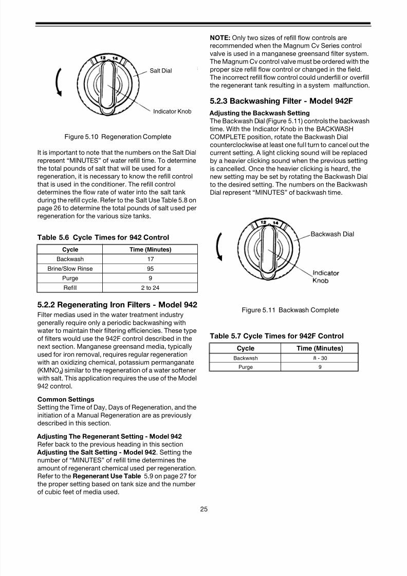
Figure 5.10 Regeneration Complete
It is important to note that the numbers on the Salt Dial
represent “MINUTES” of water refill time. To determine
the total pounds of salt that will be used for a
regeneration, it is necessary to know the refill control
that is used in the conditioner. The refill control
determines the flow rate of water into the salt tank
during the refill cycle. Refer to the Salt Use Table 5.8 onpage 26 to determine the total pounds of salt used per
regeneration for the various size tanks.
5.2.2 Regenerating Iron Filters - Model 942Filter medias used in the water treatment industry
generally require only a periodic backwashing with
water to maintain their filtering efficiencies. These type
of filters would use the 942F control described in the
next section. Manganese greensand media, typically
used for iron removal, requires regular regeneration
with an oxidizing chemical, potassium permanganate
(KMNO4 ) similar to the regeneration of a water softener
with salt. This application requires the use of the Model
942 control.
Common Settings
Setting the Time of Day, Days of Regeneration, and the
initiation of a Manual Regeneration are as previously
described in this section.
Adjusting The Regenerant Setting - Model 942
Refer back to the previous heading in this section
Adjusting the Salt Setting - Model 942. Setting the
number of “MINUTES” of refill time determines the
amount of regenerant chemical used per regeneration.
Refer to the Regenerant Use Table 5.9 on page 27 for
the proper setting based on tank size and the number
of cubic feet of media used.
NOTE: Only two sizes of refill flow controls are
recommended when the Magnum Cv Series control
valve is used in a manganese greensand filter system.
The Magnum Cv control valve must be ordered with the
proper size refill flow control or changed in the field.
The incorrect refill flow control could underfill or overfill
the regenerant tank resulting in a system malfunction.
5.2.3 Backwashing Filter - Model 942F Adjusting the Backwash Setting
The Backwash Dial (Figure 5.11) controls the backwash
time. With the Indicator Knob in the BACKWASH
COMPLETE position, rotate the Backwash Dial
counterclockwise at least one full turn to cancel out the
current setting. A light clicking sound will be replaced
by a heavier clicking sound when the previous setting
is cancelled. Once the heavier clicking is heard, the
new setting may be set by rotating the Backwash Dial
to the desired setting. The numbers on the Backwash
Dial represent “MINUTES” of backwash time.
Figure 5.11 Backwash Complete
Table 5.6 Cycle Times for 942 Control
Cycle Time (Minutes)
Backwash 17
Brine/Slow Rinse 95
Purge 9
Refill 2 to 24
Salt Dial
Indicator Knob
Table 5.7 Cycle Times for 942F Control
Cycle Time (Minutes)
Backwash 8 - 30
Purge 9
Backwash Dial

8/7/2019 1018092- Manual- Autotrol Magnum CV
http://slidepdf.com/reader/full/1018092-manual-autotrol-magnum-cv 30/8626
5.2.4 Salt Use Table
Notes:
1. Flow rates for refill controls are based on 60 psig (414 kPa) inlet pressure.
2. Take into account the type of brine system used when determining the actual amount of salt delivered duringregeneration. (i.e. dry salt/grid plate or wet salt)
3. Salt Use Table reflects minimum salting of 6 lbs./cu.ft. (96.11 kg/m3 ) through maximum salting of 15 lbs./cu.ft.
(240.27 kg/m3 ).
4. To use potassium chloride (KCl) increase salt dosage by approximately 25%.
5. Chloride/Anion dealkalizers regenerate with 5 lbs./cu.ft. (80.09 kg/m3 ) salt (NaCl) which yields approx. 7500 gr/
cu. ft. Injecting sodium hydroxide (NaOH) i.e. caustic soda, at a rate of 1/10 that of the salt dosage, during the
brine draw cycle, increases capacity to approx. 10000 gr./cu. ft. Exact capacity, based on tank size, must be
calculated using water analysis and resin manufacturer’s capacity curves.
Table 5.8 Model 942, 952, 952QC - Salt Used per Regeneration
Tank Size/Dia.inches (cm)
14 (35.5) 16 (40.6) 18 (45.7) 21 (53.3) 24 ( 60.9) 30 (76.2) 36 (91.4)
Resin Volume
cu. ft. (cu. m.)
3 (0.85) 4 (0.113) 5 (0.142) 7 (0.200)10
(0.283)
15
(0.425)
20
(0.566)Refill Flow
RateGPM (LPM)
0.7 (2.65) 0.8 (3.03) 1.0 (3.78) 1.4 (5.30) 2.0 (7.57)3.0
(11.36)
5.0
(18.93)
Salt DialSetting
(Minutes)
Approximate Pounds of Salt per Regeneration
8 18 -- -- -- -- -- 120
10 21 24 30 42 60 90 150
12 25 29 36 50 72 108 180
14 29 34 42 59 84 126 210
16 34 38 48 67 96 144 240
18 38 43 54 76 108 162 270
20 42 48 60 84 120 180 300
22 45 53 66 92 132 198 --
24 -- 60 75 105 150 225 --
8/7/2019 1018092- Manual- Autotrol Magnum CV
http://slidepdf.com/reader/full/1018092-manual-autotrol-magnum-cv 31/8627
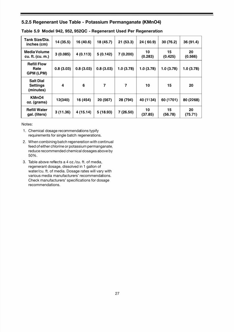
5.2.5 Regenerant Use Table - Potassium Permanganate (KMnO4)
Notes:
1. Chemical dosage recommendations typify
requirements for single batch regenerations.
2. When combining batch regeneration with continual
feed of either chlorine or potassium permanganate,
reduce recommended chemical dosages above by
50%.
3. Table above reflects a 4 oz./cu. ft. of media,
regenerant dosage, dissolved in 1 gallon of
water/cu. ft. of media. Dosage rates will vary with
various media manufacturers’ recommendations.Check manufacturers’ specifications for dosage
recommendations.
Table 5.9 Model 942, 952, 952QC - Regenerant Used Per Regeneration
Tank Size/Dia.inches (cm)
14 (35.5) 16 (40.6) 18 (45.7) 21 (53.3) 24 ( 60.9) 30 (76.2) 36 (91.4)
Media Volume
cu. ft. (cu. m.)
3 (0.085) 4 (0.113) 5 (0.142) 7 (0.200)10
(0.283)
15
(0.425)
20
(0.566)Refill Flow
RateGPM (LPM)
0.8 (3.03) 0.8 (3.03) 0.8 (3.03) 1.0 (3.78) 1.0 (3.78) 1.0 (3.78) 1.0 (3.78)
Salt DialSettings
(minutes)
4 6 7 7 10 15 20
KMnO4
oz. (grams)12(340) 16 (454) 20 (567) 28 (794) 40 (1134) 60 (1701) 80 (2268)
Refill Water
gal. (liters)
3 (11.36) 4 (15.14) 5 (18.93) 7 (26.50)10
(37.85)
15
(56.78)
20
(75.71)
8/7/2019 1018092- Manual- Autotrol Magnum CV
http://slidepdf.com/reader/full/1018092-manual-autotrol-magnum-cv 32/8628
5.3 Impulse
Series 952 Impulse Controls
The Series 952 impulse controls initiate a regeneration,
or backwash, upon receiving an external line powered
switch closer signal for a minimum of three minutes.
The three models available are:
Once the external signal is received, the control
automatically steps the valve through the appropriate
cycles. Cycle positions are identified by the Indicator
Knob.
Once the control has reached the REGENERATION
COMPLETE position, the 952 control will be ready for
the next external line powered switch closure signal. If
a switch closure signal is received during a
regeneration or backwash, it will be ignored.
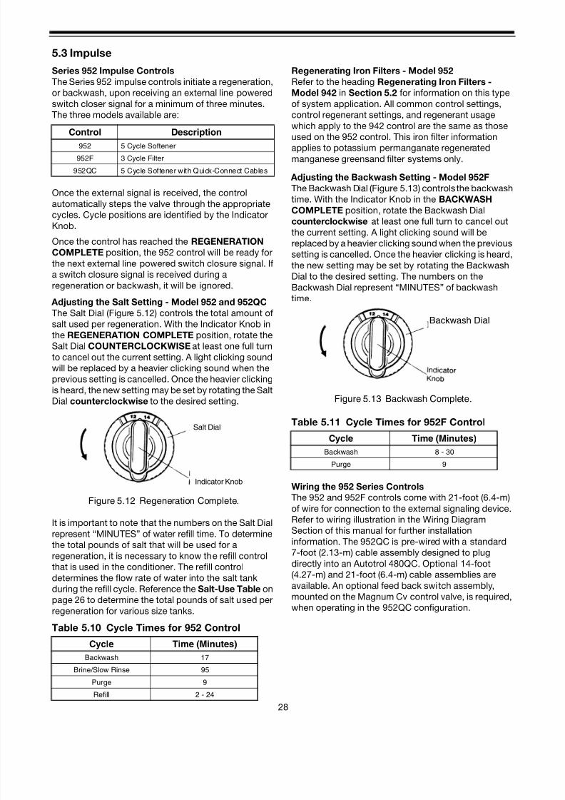
Adjusting the Salt Setting - Model 952 and 952QC
The Salt Dial (Figure 5.12) controls the total amount of
salt used per regeneration. With the Indicator Knob in
the REGENERATION COMPLETE position, rotate the
Salt Dial COUNTERCLOCKWISE at least one full turn
to cancel out the current setting. A light clicking sound
will be replaced by a heavier clicking sound when the
previous setting is cancelled. Once the heavier clicking
is heard, the new setting may be set by rotating the Salt
Dial counterclockwise to the desired setting.
Figure 5.12 Regeneration Complete.
It is important to note that the numbers on the Salt Dial
represent “MINUTES” of water refill time. To determine
the total pounds of salt that will be used for a
regeneration, it is necessary to know the refill controlthat is used in the conditioner. The refill control
determines the flow rate of water into the salt tank
during the refill cycle. Reference the Salt-Use Table on
page 26 to determine the total pounds of salt used per
regeneration for various size tanks.
Table 5.10 Cycle Times for 952 Control
Regenerating Iron Filters - Model 952
Refer to the heading Regenerating Iron Filters -
Model 942 in Section 5.2 for information on this type
of system application. All common control settings,
control regenerant settings, and regenerant usage
which apply to the 942 control are the same as those
used on the 952 control. This iron filter informationapplies to potassium permanganate regenerated
manganese greensand filter systems only.
Adjusting the Backwash Setting - Model 952F
The Backwash Dial (Figure 5.13) controls the backwash
time. With the Indicator Knob in the BACKWASH
COMPLETE position, rotate the Backwash Dial
counterclockwise at least one full turn to cancel out
the current setting. A light clicking sound will be
replaced by a heavier clicking sound when the previous
setting is cancelled. Once the heavier clicking is heard,
the new setting may be set by rotating the Backwash
Dial to the desired setting. The numbers on theBackwash Dial represent “MINUTES” of backwash
time.
Figure 5.13 Backwash Complete.
Table 5.11 Cycle Times for 952F Control
Wiring the 952 Series Controls
The 952 and 952F controls come with 21-foot (6.4-m)
of wire for connection to the external signaling device.
Refer to wiring illustration in the Wiring Diagram
Section of this manual for further installation
information. The 952QC is pre-wired with a standard
7-foot (2.13-m) cable assembly designed to plug
directly into an Autotrol 480QC. Optional 14-foot(4.27-m) and 21-foot (6.4-m) cable assemblies are
available. An optional feed back switch assembly,
mounted on the Magnum Cv control valve, is required,
when operating in the 952QC configuration.
Control Description
952 5 Cycle Softener
952F 3 Cycle Filter
952QC 5 Cycle Softener with Quick-Connect Cables
Cycle Time (Minutes)
Backwash 17
Brine/Slow Rinse 95
Purge 9
Refill 2 - 24
Salt Dial
Indicator Knob
Cycle Time (Minutes)
Backwash 8 - 30
Purge 9
Backwash Dial
8/7/2019 1018092- Manual- Autotrol Magnum CV
http://slidepdf.com/reader/full/1018092-manual-autotrol-magnum-cv 33/8629
5.4 Electronic
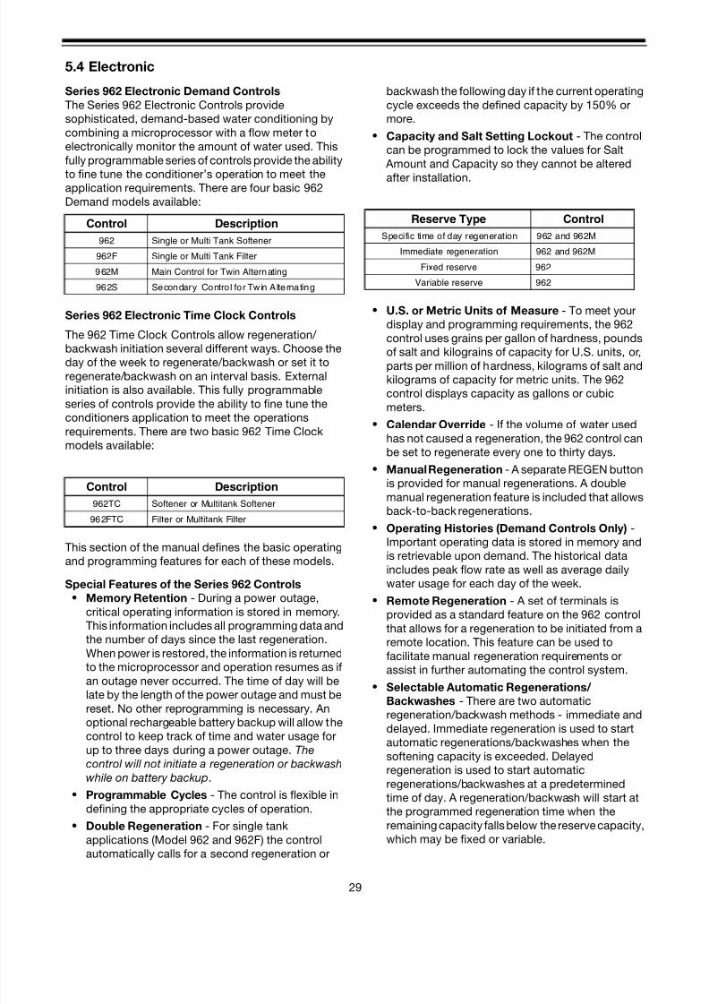
Series 962 Electronic Demand Controls
The Series 962 Electronic Controls provide
sophisticated, demand-based water conditioning by
combining a microprocessor with a flow meter to
electronically monitor the amount of water used. This
fully programmable series of controls provide the ability
to fine tune the conditioner’s operation to meet theapplication requirements. There are four basic 962
Demand models available:
Series 962 Electronic Time Clock Controls
The 962 Time Clock Controls allow regeneration/
backwash initiation several different ways. Choose theday of the week to regenerate/backwash or set it to
regenerate/backwash on an interval basis. External
initiation is also available. This fully programmable
series of controls provide the ability to fine tune the
conditioners application to meet the operations
requirements. There are two basic 962 Time Clock
models available:
This section of the manual defines the basic operating
and programming features for each of these models.
Special Features of the Series 962 Controls
• Memory Retention - During a power outage,
critical operating information is stored in memory.
This information includes all programming data and
the number of days since the last regeneration.
When power is restored, the information is returned
to the microprocessor and operation resumes as if
an outage never occurred. The time of day will be
late by the length of the power outage and must be
reset. No other reprogramming is necessary. An
optional rechargeable battery backup will allow the
control to keep track of time and water usage for
up to three days during a power outage. The
control will not initiate a regeneration or backwash
while on battery backup.
• Programmable Cycles - The control is flexible in
defining the appropriate cycles of operation.
• Double Regeneration - For single tank
applications (Model 962 and 962F) the control
automatically calls for a second regeneration or
backwash the following day if the current operating
cycle exceeds the defined capacity by 150% or
more.
• Capacity and Salt Setting Lockout - The control
can be programmed to lock the values for Salt
Amount and Capacity so they cannot be altered
after installation.
• U.S. or Metric Units of Measure - To meet your
display and programming requirements, the 962
control uses grains per gallon of hardness, pounds
of salt and kilograins of capacity for U.S. units, or,parts per million of hardness, kilograms of salt and
kilograms of capacity for metric units. The 962
control displays capacity as gallons or cubic
meters.
• Calendar Override - If the volume of water used
has not caused a regeneration, the 962 control can
be set to regenerate every one to thirty days.
• Manual Regeneration - A separate REGEN button
is provided for manual regenerations. A double
manual regeneration feature is included that allows
back-to-back regenerations.
• Operating Histories (Demand Controls Only) -Important operating data is stored in memory and
is retrievable upon demand. The historical data
includes peak flow rate as well as average daily
water usage for each day of the week.
• Remote Regeneration - A set of terminals is
provided as a standard feature on the 962 control
that allows for a regeneration to be initiated from a
remote location. This feature can be used to
facilitate manual regeneration requirements or
assist in further automating the control system.
• Selectable Automatic Regenerations/
Backwashes - There are two automaticregeneration/backwash methods - immediate and
delayed. Immediate regeneration is used to start
automatic regenerations/backwashes when the
softening capacity is exceeded. Delayed
regeneration is used to start automatic
regenerations/backwashes at a predetermined
time of day. A regeneration/backwash will start at
the programmed regeneration time when the
remaining capacity falls below the reserve capacity,
which may be fixed or variable.
Control Description
962 Single or Multi Tank Softener
962F Single or Multi Tank Filter
962M Main Control for Twin Alternating
962S Secondary Control for Twin Alternating
Control Description
962TC Softener or Multitank Softener
962FTC Filter or Multitank Filter
Reserve Type Control
Specific time of day regeneration 962 and 962M
Immediate regeneration 962 and 962M
Fixed reserve 962
Variable reserve 962

8/7/2019 1018092- Manual- Autotrol Magnum CV
http://slidepdf.com/reader/full/1018092-manual-autotrol-magnum-cv 34/8630
• Selectable Reserve Options (Demand Controls
Only) - To meet the conditioned water
requirements of the application, the 962 control
allows selection of one of two reserve types:
– Fixed Reserve - The reserve is fixed at a
progammable percentage (30% factory preset)
of the total softening capacity.
– Variable Reserve - The controller monitors the
daily water usage and at the programmed timeof regeneration, calculates the average water
used for each day of the week. The reserve
capacity is set to 120% of the average water
usage for the next day.
• Delayed Regeneration on Twin-alternating
Systems - The twin-alternating system does not
use a reserve capacity. The service tank switches
when the softening capacity is exhausted.
Regeneration of the exhausted tank will occur at
the specified time of day when using the delayed
regeneration feature.
• Immediate Regeneration on Twin and TripleParallel Systems - The twin and triple parallel
systems use a reserve capacity of “0” along with
immediate regeneration. Regeneration of an
exhausted tank in the system, will occur
immediately after reaching its maximum capacity,
IF, there are no other tanks, within the system,
already regenerating.
Normal Display Modes
In the normal operating mode the Series 962 control
will alternate between Capacity Remaining (gallons or
m3 ) and Flow Rate (gallons per minute or m/hr). In the
event of power loss, the display will alternate betweenTime of Day and Capacity Remaining once power
has been restored. The normal operating display mode
of the twin alternating, parallel system scrolls through
three displays. They are: Capacity Remaining of tank
1 in gallons, Capacity Remaining of tank 2 in gallons,
and Flow Rate. If a power outage has occurred, the
flow rate display will change to Time of Day. In both
cases the control will remain in Power Loss display
mode until the Time of Day is reset or until any button
is pressed. (Electronic Time Clock displays Time of Day
only).
Programming the Series 962 ControlsThis section contains common aspects of
programming the 962, 962F, and 962M controls and
retrieving historical operating data. The 962S control is
a secondary unit that always works in conjunction with
the 962M main control for twin alternating tank
applications. The operating values for the 962S are the
same as the operating values in the 962M control. An
adhesive installation label is provided with each 962,
962F, and 962M control. It is recommended that this be
filled out with programming parameters on start-up and
placed on the inside of the cam cover.
Factory Default Values - The control is shipped from
the factory with a default value for Salt Amount of 10 lb.
(4 kg for metric units). Capacity, Hardness, Refill and
Brine Draw values are set to 0 and must be changed
to appropriate values before the control will
operate. “Err 4” will be displayed until a valid
number is entered for each of these items. Program
variable P12 is preset at the factory to define the U.S.
units of measure for North American application ormetric units of measure for application outside North
America.
Program Levels - The Series 962 controls have been
designed to facilitate different levels of programming
requirements. Level I includes program variables that
are frequently referenced by users, operators,
installers, and service personnel, and is accessible
without the requirement of codes. Level II includes
variables that are most typically used at the time of
installation and initial setup and is accessible with
special access codes. Level III locations are used
primarily for accessing operating history information.Level III parameters also require access codes.
Programming levels are further defined in Section 6
(page 34).
Table I on page 34 lists the Level I program values for
the 962, 962F, 962TC, 962FTC and 962M controls.Tables IIA through IIE, on pages 35-41, list the Level II
program values for all 962 series controls.
Program Values and Locations - The P values that
are programmed into the Series 962 controls are listed
in the Level I and Level II tables.
Locating a Program Value - To locate and display a P
value in Level I press the UP [↑ ] or DOWN [↓] arrow
button until the desired value is displayed.
To locate and display a P value in Level II,
simultaneously press the UP [↑ ] and DOWN [↓] arrow
buttons for 3 seconds to gain access. Press the UP [↑
]or DOWN [↓] arrow buttons until the desired location is
displayed. Press LEFT [←] to display a value in P
locations.
To locate and display an L value in Level III,
simultaneously press the LEFT [←] and UP [↑ ] arrow
buttons for 3 seconds to gain access and the press the
UP [↑ ] or DOWN [↓] arrows buttons until the desired
location is displayed. Press LEFT [←] to display value in
the L location.
Levels Access Code
I None required
IIPress and hold the ↑ ↓ for approximately
3 seconds
IIIPress and hold the ←↑ arrow buttons for
approximately 3 seconds
8/7/2019 1018092- Manual- Autotrol Magnum CV
http://slidepdf.com/reader/full/1018092-manual-autotrol-magnum-cv 35/8631
Changing a Program Value - Once the P value you
want to change is displayed, press the LEFT [←] arrow
button to display the current entry for that value. To
change or modify the value, press the SET button. The
character on the right hand side of the display will begin
to flash. Use the UP [↑ ] or DOWN [↓] arrow buttons to
select the desired entry. Once the desired entry is
obtained, press the LEFT [←] button to move to the next
character and change as needed. Once you havecompleted the appropriate changes, press the SET
button. When you press the SET button the new entry
is stored and the control automatically scrolls to the
next P value. If a beep sounds, the new entry was not
accepted. Tables I and II list the range available for a
specific program value.
Exit Mode - To exit the Level II programming mode,
simultaneously press and hold the UP [↑ ] and DOWN
[↓] arrow buttons for 3 seconds, or wait 30 seconds
without pressing a button, and the display will return to
alternate between Capacity Remaining and Flow Rate.
Level I Program Values (Table I)
Level I Program Values are identified by the legend on
the faceplate of the control. Each Level I P value has a
green LED that is illuminated when displayed.
Following are the Level I P values:
• Time of Day P1
• Time of Regen P2
• Hardness P3
• Salt Amount P4
• Capacity P5
Time of Day - How to Change AM and PMPress the SET button. The display will show the Time of
Day with the minutes digit blinking. To change this
number press the UP [↑ ] arrow button to increase the
number or the DOWN [↓] arrow button to decrease the
number. To skip the number without changing, press
the LEFT [←] arrow button. The first digit will stop
flashing and the next digit will start flashing. You can
only change the flashing number. When the far left digit
is reached, pressing the LEFT [←] arrow button returns
the flashing to the far right digit. Continue changing
numbers until the desired Time of Day is displayed.
Press the SET button to enter the value.
Use the same procedure to modify any of the other
Level I or Level II P values.
The PM indicator is set when changing the left most
digit in the time display. The left most digit will be a zero
"O" or a "1”. When the PM indicator light is illuminated
the time will be PM.
Level II Program Values (Tables IIA, IIB, IIC, IID, IIE
and III)
The Level II Parameters are defined as P6 through P22.
The available range for the Refill Controller (P6), and the
Brine Draw Value (P7), may be found in the section
entitled Performance Data and Charts Section of this
manual (pages 57 and 58).
Table IV on page 43 lists the Level III historical data.
Manual Regeneration or Backwash
To initiate a manual regeneration or backwash, simply
press and hold the REGEN button for 3 seconds. If an
immediate second regeneration or backwash is
desired, wait for at least one minute after the first
regeneration or backwash begins and then press and
hold the REGEN button for 3 seconds. A second
regeneration or backwash will be performed
immediately following the first. The display will freeze
and only show the Regeneration Time Remaining as an
indication that the second regeneration or backwash
will be initiated.
When the first regeneration or backwash is complete,
the second regeneration or backwash will begin and
the display will alternate between Flow Rate and
Regeneration Time Remaining.
Note: Series 962M and 962S Twin Alternating Systems
have a two minute time period, after the manual
regeneration button is pressed, where the standby unit
drives to service. If an immediate second regeneration
is required of the OTHER unit in the system, wait for at
least three minutes after pressing the manual
regeneration button the first time, then press and holdthe REGEN button for three seconds.
Battery Backup
If the battery backup is provided with the Series 962
control, make sure that it is properly connected.
Reference pages 32 and 33. Water usage and time of
day will be maintained. The control has a trickle charge
circuit that will recharge the battery in the event it is
depleted by a power outage.
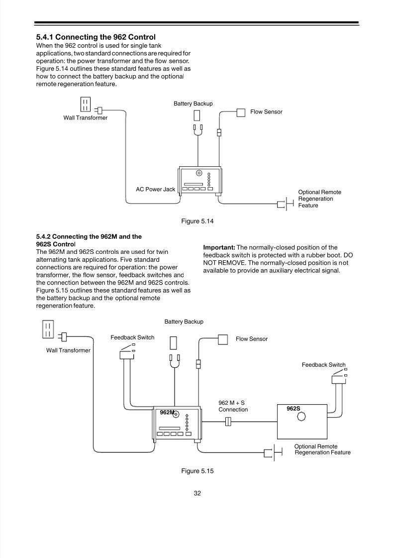
8/7/2019 1018092- Manual- Autotrol Magnum CV
http://slidepdf.com/reader/full/1018092-manual-autotrol-magnum-cv 36/8632
5.4.1 Connecting the 962 ControlWhen the 962 control is used for single tank
applications, two standard connections are required for
operation: the power transformer and the flow sensor.
Figure 5.14 outlines these standard features as well as
how to connect the battery backup and the optional
remote regeneration feature.
Figure 5.14
5.4.2 Connecting the 962M and the
962S Control
The 962M and 962S controls are used for twin
alternating tank applications. Five standard
connections are required for operation: the power
transformer, the flow sensor, feedback switches and
the connection between the 962M and 962S controls.
Figure 5.15 outlines these standard features as well asthe battery backup and the optional remote
regeneration feature.
Important: The normally-closed position of the
feedback switch is protected with a rubber boot. DO
NOT REMOVE. The normally-closed position is not
available to provide an auxiliary electrical signal.
Figure 5.15
Wall Transformer
AC Power Jack
Battery Backup
Flow Sensor
Optional RemoteRegenerationFeature
Wall Transformer
Feedback Switch
Battery Backup
Flow Sensor
962 M + SConnection
Optional RemoteRegeneration Feature
Feedback Switch
962S962M

8/7/2019 1018092- Manual- Autotrol Magnum CV
http://slidepdf.com/reader/full/1018092-manual-autotrol-magnum-cv 37/8633
5.4.3 Connecting the 962 Twin and TripleParallel ControlThe 962 control can be used for twin and triple tank
applications, operating in a parallel mode. Six standard
connections are required for twin parallel operations;
the power transformer and flow sensor for each control
and the twin interconnecting cable between the
controls. Nine standard connections are required for
triple parallel operation: the power transformer and flow
sensor for each control and the triple interconnecting
cable between the controls. Figure 5.16 outlines these
standard features, as well as the battery backup and
the optional remote regeneration feature.
Figure 5.16
Twin Cable Triple Cable
PARALLEL SYSTEM CONNECTION PROCEDURE
Connect turbine flow meters
Connect interlock cables
Attach optional batteries
Plug transformers into outlets on common circuit
1
2
3
4
PARALLEL INTERCONNECT CABLES
PN 1034312 - Twin System Cable - 10 feetPN 1035587 - Triplex System Cable - 10 feeteachPN 1035593 - Extension Cable - 2 feet
Optional RemoteRegeneration Feature

8/7/2019 1018092- Manual- Autotrol Magnum CV
http://slidepdf.com/reader/full/1018092-manual-autotrol-magnum-cv 38/8634
6.0 Programming Tables
6.1 Table I - Level 1 Values
Level I Program Values for 962, 962F, 962TC, 962FTC, and 962M Controls
Level II, III values on following pages.
Description ofProgram Values
Range of ValuesMin.
Incre-
ment
SettingFactoryValue
Units ofMeasure
Notes
P1Day of Week
Time of day
1:00 - 12:59 AM/PM
00:00 - 23:591 None hour:minute
Range depends
on value
selected for P13.
For day of week
Sun = 1, Mon =
2, Tues = 3, Wed
= 4, Thurs = 5,
Fri = 6, Sat = 7.
P2Time of day to start
regeneration
1:00 - 12:59 AM/PM
00:00 - 23:591 None
hour:minute
Range depends
on value
selected for P13
For 962M, used
only if P15 = 1
P3 Hardness of water3-250
30-2500
1
10
0
0
grains/gallon
(ppm)
Unit of measure
depends on
value selected
for P12
P4 Salt amount5-1250
2-500
5
2
10
4
pounds
(kilograms)
Unit of measure
and factory value
depends on
value selected
for P12
P5 Capacity of unit 1-26000.1-260.0 10.1 00 kilograins(kilograms)
Unit of measure
depends onvalue selected
for P12

8/7/2019 1018092- Manual- Autotrol Magnum CV
http://slidepdf.com/reader/full/1018092-manual-autotrol-magnum-cv 39/8635
6.2 Table IIA
Level II Program Values - 962 Single Twin or Triple Parallel Tank Softener or Dealkalizer (P17=0)
Note: This programming sheet is for use with controls
manufactured after 09 Aug 2000.
ParameterDescription of
Program ValuesRange of Values
Min.
Increment
Factory
ValueUnits of Measure Notes
P1 Day of Week and
Time of day
(1-7) 1:00 - 12:59
AM or PM
Metric (1-7)
0:00 - 23:59
(1 day)
1 minute
None Hour
Minute
Range depends on value selected for
P13. For day of week SUN=1, MON=2,
TUE=3, WED=4, THU=5, FRI=6, SAT=7.
P2 Time of day to start
regeneration
1:00 - 12:59
AM or PM
00:00 - 23:59
1 None Hour
Minute
Range depends on value selected for
P13 Use only if P15 = 0 or 1
P3 Hardness of water 3-250
30-2500
1
10
0
0
Grains per gallon
ppm
Unit of measure depends on value
selected for P12
P4 Salt amount 5 – 1250
2 - 500
5
2
10
4
Pounds
Kilograms
Unit of measure and factory value
depends on value selected for P12
P5 Capacity of unit 1-2600
0.1-260.0
1
0.1
0
0
Kilograins
Kilograms
Unit of measure depends on value
selected for P12
P6 Refill controller 2 - 99 1 0 Selected from chart in Performance Data
Sections, page 57
P7 Brine draw rate 2 - 99 1 0 Selected from chart in Performance Data
Sections, page 58
P9 Backwash time 4 - 30 1 14 Minutes May be adjusted for application
P10 Rinse time 7 - 125 1 40 Minutes May be adjusted for application
P11 Purge time 2 - 19 1 4 Minutes May be adjusted for application
P12 Units of measure 0 - 1 1 0 0 = US, 1 = Metric
P13 Clock mode 0 - 1 1 0 0 = 12 hour clock, 1 = 24 hour clock
P14 Calendar override 0 - 30 1 0 Days 0 = no calendar override
P15 Reserve Type 0 - 3 1 0 0=Variable Reserve, 1=Fixed Reserve
2=Variable Reserve with immediate
regeneration , 3=Fixed Reserve with
immediate regeneration
P16 Initial average
usage or fixed
reserve
0 - 70 1 30 Percent of Total
capacity
P17 Operation type 0 - 2 1 0 0 = Single or Parallel
P18 Salt/Capacity
Change Lock Out
0 - 1 1 0 0 = none, 1 = Salt /Capacity Change
Locked Out
P19 Flow Sensor select 2 1 = 1.0" Autotrol turbine, 2 = 2.0” Autotrol
turbine, 3 = User defined K-factor, 4 =
User defined pulse equivalent
P20 K-factor or Pulse
equivalent
0.01 - 255.00 .01 0.01 Number used for Meter K-factor or Pulse
equivalent
P21 Remote
Regeneration
Switch Delay
1 - 254 1 60 Seconds Time remote switch must be active to
start a regeneration.
P22 Factory Use Only
– DO NOT
CHANGE
99 Do not change

8/7/2019 1018092- Manual- Autotrol Magnum CV
http://slidepdf.com/reader/full/1018092-manual-autotrol-magnum-cv 40/8636
6.3 Table IIB
Level II Program Values - 962F Single Tank Filter (P17=4)
ParameterDescription of
ParameterRange of Values
Min.
Increment Factory Value Units of Measure Notes
P1 Day of Week and
Time of day
1:00 - 12:59
AM or PM
0:00 - 23:59
1 None Day
Hour:Minute
Range depends on value selected for
P13
P2 Time of day to start
regeneration
1:00 - 12:59 AM or PM
00:00 - 23:59
1 2:00 AM Hour:Minute Range depends on value selected for
P13. Use only if P15 =1
P3 Factory 10
100
Grains per gallon
ppm
Unit of measure depends on value
selected for P12
P4 Salt amount 0.5 – 125.0
0.2 - 50.0
0.5
0.2
0.5
0.2
Pounds
Kilograms
Unit of measure and factory value
depend on value selected for P12
P5 0 U.S. - Divide the volumetric capacity
(gallons) of the filter by 100 and enter
this number into P5.
Metric - Divide the volumetric capacity
(cubic meters) by 10 and enter this
number into P5.P6 Refill controller 2 - 200 1 200 gpm x 100 Do not change.
P7 Brine draw rate 2 - 200 1 200 gpm x 100 Do not change.
P9 Backwash time 7 - 60 1 14 Minutes May be adjusted for application.
P10 Does not apply 7 - 125 1 8 Minutes Do not change
P11 Purge time 9 - 60 1 9 Minutes May be adjusted for application.
P12 Units of measure 0 - 1 1 0 0 = US, 1 = Metric
P13 Clock mode 0 - 1 1 0 0 = 12 hour clock, 1 = 24 hour clock
P14 Calendar override 0 - 30 1 0 Days 0 = no calendar override
P15 Reserve Type 0 - 3 1 0 0 = variable reserve 1 = fixed reserve,
2 = variable reserve with immediate
regen, 3 = fixed reserve with immediate
regen.
P16 Initial average
usage or fixed
reserve
0 - 70 1 30 Percent of Total
capacity
Description depends on value entered
for P15.
P17 Operation type 0 - 7 4 0 4 = filter
P18 Salt/Capacity
Change Lock Out
0 - 1 1 0 0 = none 1 = Salt /Capacity Change
Locked Out
P19 Flow Sensor select 1 - 4 1 2 1 = 1.0" Autotrol Turbine
2 = 2.0” Autotrol Turbine
3 = User defined K-factor
4 = User defined pulse equivalent
P20 K-factor or Pulse
equivalent
0.01 -255.00 0.01 0.01 Number used for Meter K-factor or
Pulse equivalent
P21 Remote
Regeneration
Switch Delay
1 - 254 1 60 Seconds Time remote switch must be active to
start a regeneration.
P22 Factory Use Only 0 - 9 1 99 Do not change.

8/7/2019 1018092- Manual- Autotrol Magnum CV
http://slidepdf.com/reader/full/1018092-manual-autotrol-magnum-cv 41/8637
6.4 Table IIC
Level II Program Values - 962 Twin Tank Alternating Softener (P17=2)
ParameterDescription of
Program ValuesRange of Values
Min.
Increment
Factory
ValueUnits of Measure Notes
P1 Day of Week and
Time of day
(1-7) 1:00 - 12:59
AM or PM
Metric
(1-7) 0:00 - 23:59
(1 day)
1 minute
None Hour
Minute
Range depends on value selected for
P13. For day of week SUN=1, MON=2,
TUE=3, WED=4, THU=5, FRI=6, SAT=7.
P2 Time of day to start
regeneration
1:00 - 12:59 AM or PM
00:00 - 23:59
1 None Hour
Minute
Range depends on value selected for
P13. Use only if P15 =1
P3 Hardness of water 3-250
30-2500
1
10
0
0
Grains per gallon
ppm
Unit of measure depends on value
selected for P12
P4 Salt amount 5 – 1250
2 - 500
5
2
10
4
Pounds
Kilograms
Unit of measure and factory value
depend on value selected for P12
P5 Capacity of unit 1-2600
0.1-260.0
1
0.1
0 Kilograins
Kilograms
Total capacity for each tank. Unit of
measure depends on value selected for
P12
P6 Refill controller 2 - 99 1 0 Selected from chart in
Performance Data Sections, page 57
P7 Brine draw rate 2 - 99 1 0 Selected from chart in
Performance Data Sections, page 58
P9 Backwash time 4 - 30 1 14 Minutes
P10 Rinse time 7 - 125 1 40 Minutes
P11 Purge time 2 - 19 1 4 Minutes
P12 Units of measure 0 - 1 1 0 0 = US, 1 = Metric
P13 Clock mode 0 - 1 1 0 0 = 12 hour clock, 1 = 24 hour clock
P14 Calendar override 0 - 30 1 0 Days 0 = no calendar override
P15 Regeneration
delay
0 - 1 1 0 0 = Immediate regeneration
1 = Regeneration delayed until time pro-
grammed in P2 is reached
P16 Capacity that must
be left on 2nd tank
to permit delayed
regeneration of 1st
tank
0 - 70 1 30 Percent of Total
capacity
Used only if P15 is set to 1
P17 Operation type 0 - 2 1 2 2 = Twin Alternating
P18 Salt/Capacity
Change Lock Out
0 - 1 1 0 0 = none 1 = Salt /Capacity Change
Locked Out
P19 Flow Sensor select 2 1 = 1.0" Autotrol Turbine, 2 = 2.0”
Autotrol Turbine, 3 = User defined
K-factor, 4 = User defined pulse
equivalent
P20 K-factor or Pulse
equivalent
0.01 -255.00 .01 0.01 Number used for Meter K-factor or Pulse
equivalent
P21 Remote
Regeneration
Switch Delay
1 - 254 1 60 Seconds Time remote switch must be active to
start a regeneration.
P22 Factory Use Only
– DO NOT
CHANGE
99 Do not change

8/7/2019 1018092- Manual- Autotrol Magnum CV
http://slidepdf.com/reader/full/1018092-manual-autotrol-magnum-cv 42/8638
6.5 Table IID
Level II Program Values - Electronic Timeclock Filter (P17=7)
Parameter Description Range of ValuesMin.
IncrementFactory Value
Units of
MeasureNotes
P1 Day of Week
and Time of day
(1-7) 1:00 - 12:59
AM or PM
Metric
(1-7) 0:00 - 23:59
(1 day)
1 minute
Current Day and
Time
Hour
Minute
Range depends on value selected for
P13
For day of week SUN=1, MON=2,
TUE=3, WED=4, THU=5, FRI=6,SAT=7. THIS IS THE LEFT MOST
DIGIT ON THE DISPLAY
P2 Time of day to
start regenera-
tion
1:00 - 12:59
AM or PM
00:00 - 23:59
As required Hour
Minute
Range depends on value selected for
P13 Use only if P15 = 0 or 1
P3 Factory 10
P4 Does not apply 0.5
0.2
P5 Factory 10 U.S.- Divide the volumetric capacity
(gallons) of the filter by 100 and enter
this number into P5
Metric - Divide the volumetric
capacity (cubic meters) by 10 and
enter this number into P5
P6 Refill controller 2 - 200 1 200 Do not change
P7 Brine draw rate 2 - 200 1 200 Do not change
P9 Backwash time 7 - 60 1 14 Minutes May be adjusted for application
P10 Does not apply 7 - 125 1 8 Minutes May be adjusted for application
P11 Fast Rinse 9 - 60 1 9 Minutes May be adjusted for application
P12 Units of
measure
0 - 1 1 0 0 = US, 1 = Metric
P13 Clock mode 0 - 1 1 0 0 = 12 hour clock, 1 = 24 hour clock
P14 Interval
Regeneration
0 - 30 1 0 Days
between
regeneration
0 = No Interval chosen - *May be
adjusted for application
P15 Does not apply
for Timeclock
operation
0
P16 Does not apply
for Timeclock
operation
30
P17 Operation type 7 7 = Filter TimeClock
P18 Salt Change
Lock Out
0 - 1 1 0 0 = none 1 = Salt /Capacity Change
Locked Out
P19 Does not apply
for Timeclock
operation
P20 Does not apply
for Timeclock
operation
P21 Remote
Regeneration
Switch Delay
1 - 254 1 60 Seconds Time remote switch must be active to
start regeneration.
P22 Factory Use
Only – DO NOT
CHANGE
99 Do not change
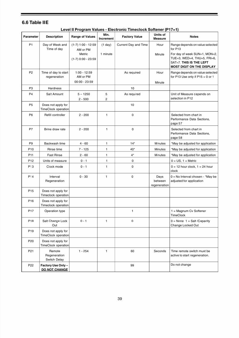
8/7/2019 1018092- Manual- Autotrol Magnum CV
http://slidepdf.com/reader/full/1018092-manual-autotrol-magnum-cv 43/8639
6.6 Table IIE
Level II Program Values - Electronic Timeclock Softener (P17=1)
Parameter Description Range of ValuesMin.
IncrementFactory Value
Units of
MeasureNotes
P1 Day of Week and
Time of day
(1-7) 1:00 - 12:59
AM or PM
Metric
(1-7) 0:00 - 23:59
(1 day)
1 minute
Current Day and Time Hour
Minute
Range depends on value selected
for P13
For day of week SUN=1, MON=2,
TUE=3, WED=4, THU=5, FRI=6,SAT=7. THIS IS THE LEFT
MOST DIGIT ON THE DISPLAY
P2 Time of day to start
regeneration
1:00 - 12:59
AM or PM
00:00 - 23:59
As required Hour
Minute
Range depends on value selected
for P13 Use only if P15 = 0 or 1
P3 Hardness 10
P4 Salt Amount 5 – 1250
2 - 500
5
2
As required Unit of Measure depends on
selection in P12
P5 Does not apply for
TimeClock operation
10
P6 Refill controller 2 - 200 1 0 Selected from chart in
Performance Data Sections,
page 57
P7 Brine draw rate 2 - 200 1 0 Selected from chart in
Performance Data Sections,
page 58
P9 Backwash time 4 - 60 1 14* Minutes *May be adjusted for application
P10 Rinse time 7 - 125 1 40* Minutes *May be adjusted for application
P11 Fast Rinse 2 - 60 1 4* Minutes *May be adjusted for application
P12 Units of measure 0 - 1 1 0 0 = US, 1 = Metric
P13 Clock mode 0 - 1 1 0 0 = 12 hour clock, 1 = 24 hour
clock
P14 IntervalRegeneration
0 - 30 1 0 Daysbetween
regeneration
0 = No Interval chosen - *May beadjusted for application
P15 Does not apply for
Timeclock operation
P16 Does not apply for
Timeclock operation
P17 Operation type 1 1 = Magnum Cv Softener
TimeClock
P18 Salt Change Lock
Out
0 - 1 1 0 0 = None 1 = Salt /Capacity
Change Locked Out
P19 Does not apply for
TimeClock operationP20 Does not apply for
TimeClock operation
P21 Remote
Regeneration
Switch Delay
1 - 254 1 60 Seconds Time remote switch must be
active to start regeneration.
P22 Factory Use Only –
DO NOT CHANGE
99 Do not change

8/7/2019 1018092- Manual- Autotrol Magnum CV
http://slidepdf.com/reader/full/1018092-manual-autotrol-magnum-cv 44/8640
6.7 Explanation of Parameter Values for the 962 Single and Parallel Tank Controls
This section contains a detailed explanation of the programming parameters in the 962 electronic control.
NumberDescription of
Program ValuesExplanation
P1* Time of Day The day of the week is displayed with the time of day in the far left digit . It is programmed at P1, the same
as the time of day. The day of week will automatically increment at midnight. This will allow correlation to
the daily usage history stored in L7 through L13 to days of the week. Customer should use day 1 = Sun-
day through day 7 = Saturday. Then L7 will hold the usage history for Sunday through L13 holding theusage history for Saturday. The daily averages stored in the L-values will still be updated at the time of
regeneration, not midnight. This is required to keep an accurate record for reserve capacity needed at the
time of regeneration. Customers should understand that the L-value displayed for the average water
usage for Sunday “day one” will be the average water usage for Sunday at 2:00 a.m. to Monday at 2:00
a.m. assuming the time of regeneration is set for 2:00 a.m. Customers can reduce this two hour shift by
setting the time of regeneration to 12:01 a.m.
P2* Time of
Regeneration
If P15 is set at 0 (smart reserve), the unit will check at the P2 time to see if the smart reserve capacity has
been reached. If it has, the unit WILL regenerate at the specified P2 time. If the capacity display reaches
zero gallons (m3) at any time during the day, the unit will NOT regenerate until the specified P2 time is
reached.
If P15 is set at 1 (fixed reserve), the unit will check at the P2 time to see if the fixed reserve capacity (P16)
has been reached. If it has, the unit WILL regenerate at the specified P2 time. If the capacity display
reaches zero gallons (m3
) at any time during the day, the unit will NOT regenerate until the specified P2time is reached.
If P15 is set at 2 (smart reserve with immediate regen), the unit will check at the P2 time to see if the
smart capacity has been reached. If it has, the unit will regenerate at the specified P2 time. If the capacity
display reaches zero gallons (m3) at any time during the day, the unit WILL regenerate immediately. It will
ALSO continue checking at the specified P2 time to see if the fixed reserve capacity has been reached,
initiating a regeneration at the P2 time if it has. If the fixed reserve is set to zero, the unit will ONLY
regenerate when the capacity display reaches zero.
If P15 is set to 3 the unit will operate almost exactly the same as if it were set to 1. The only difference
when set to 3 is that if the capacity were to reach zero at any time the unit will initiate an immediate
regeneration.
If calendar override is used P14), the unit will regenerate every 1 to 30 days at the specified P2 time.
Fixed Reserve: Fixed percentage of capacity defined by user (gallons) (m3).
Smart Reserve: 120% of the daily average (gallons) (m3) calculated from historical values stored in
NOVRAM.
P3** Hardness of water If the 962 controller is programmed at P12 to use U.S. units, enter hardness in grains per gallon (gpg). If
the 962 controller is programmed at P12 to use metric units, enter hardness in parts per million (ppm).
P4** Salt Amount Enter your TOTAL salt amount per regeneration. For example, salting at 10 lb (4.5 kg) per cubic foot on a
unit with 3 cubic feet of resin, enter 30 (10 lb/ft3) x (3 ft3) = 30 lb. salt. [(4.5 kg/ft3) x (3 ft3) = 13.6 kg salt].
P5 Capacity of Unit Enter the capacity of the unit here, in kilograins (kilograms). For example, a 3 ft3 unit with a resin capacity
of 25,000 grains (1620 grams) per ft3, enter 75 here. (25,000 grains/ft3) x (3 ft3 = 75,000 grains = 75
kilograins.
[(1620 grams/ft3) x (3 ft3) = 4860 grams = 4.86 kilograms].
Note: 15 lb/cu ft salting yields 30,000 grains/cu ft resin
10 lb/cu ft salting yields 25,000 grains, cu ft resin
6 lb/cu ft salting yields 20,000 grains/cu ft resin
Reduced salting yields a reduced capacity1 kilograin (1000 grains) = 0.0648 kilograms (64.8 grams)
P6 Refill controller This value is the refill flow rate times 10, rounded to the next whole number. For example, on a 16-inch
tank, the refill control has a flow rate of 0.8 gpm. Calculate: 0.8 gpm x 10 = 8. Enter 8.
P7 Brine draw rate This is the injector draw rate times 10, rounded to the next whole number. For example, on a 16-inch tank,
the injector has a draw rate of 0.8 gpm. Enter 8 (0.8 gpm x 10 = 8).
P8 Not used P8 is reserved for furture use.
P9 Backwash time Self explanatory. Generally, 5 to 15 minutes or until water runs clear or specific water conservation needs
are met.
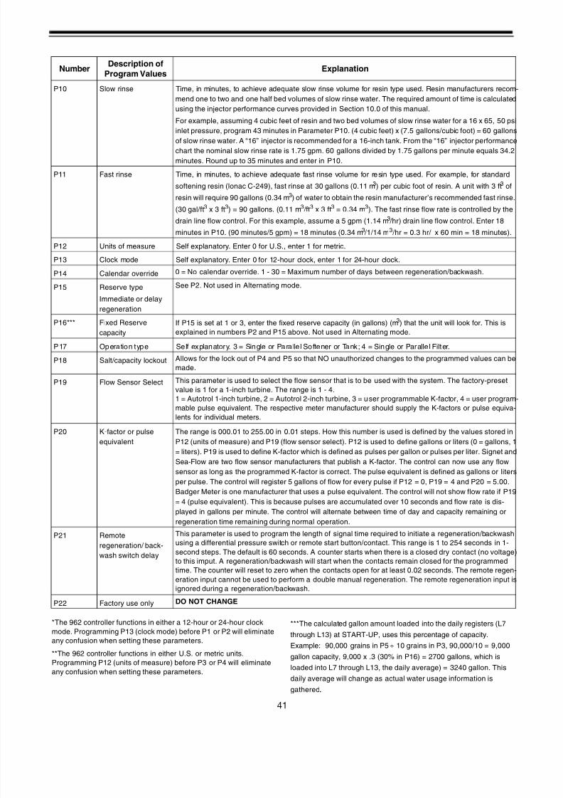
8/7/2019 1018092- Manual- Autotrol Magnum CV
http://slidepdf.com/reader/full/1018092-manual-autotrol-magnum-cv 45/8641
*The 962 controller functions in either a 12-hour or 24-hour clock
mode. Programming P13 (clock mode) before P1 or P2 will eliminate
any confusion when setting these parameters.
**The 962 controller functions in either U.S. or metric units.
Programming P12 (units of measure) before P3 or P4 will eliminate
any confusion when setting these parameters.
***The calculated gallon amount loaded into the daily registers (L7
through L13) at START-UP, uses this percentage of capacity.
Example: 90,000 grains in P5 ÷ 10 grains in P3, 90,000/10 = 9,000
gallon capacity, 9,000 x .3 (30% in P16) = 2700 gallons, which is
loaded into L7 through L13, the daily average) = 3240 gallon. This
daily average will change as actual water usage information is
gathered.
P10 Slow rinse Time, in minutes, to achieve adequate slow rinse volume for resin type used. Resin manufacturers recom-
mend one to two and one half bed volumes of slow rinse water. The required amount of time is calculated
using the injector performance curves provided in Section 10.0 of this manual.
For example, assuming 4 cubic feet of resin and two bed volumes of slow rinse water for a 16 x 65, 50 psi
inlet pressure, program 43 minutes in Parameter P10. (4 cubic feet) x (7.5 gallons/cubic foot) = 60 gallons
of slow rinse water. A “16” injector is recommended for a 16-inch tank. From the “16” injector performancechart the nominal slow rinse rate is 1.75 gpm. 60 gallons divided by 1.75 gallons per minute equals 34.2
minutes. Round up to 35 minutes and enter in P10.
P11 Fast rinse Time, in minutes, to achieve adequate fast rinse volume for resin type used. For example, for standard
softening resin (lonac C-249), fast rinse at 30 gallons (0.11 m3) per cubic foot of resin. A unit with 3 ft3 of
resin will require 90 gallons (0.34 m3) of water to obtain the resin manufacturer’s recommended fast rinse.
(30 gal/ft3 x 3 ft3) = 90 gallons. (0.11 m3 /ft3 x 3 ft3 = 0.34 m3). The fast rinse flow rate is controlled by the
drain line flow control. For this example, assume a 5 gpm (1.14 m3 /hr) drain line flow control. Enter 18
minutes in P10. (90 minutes/5 gpm) = 18 minutes (0.34 m3 /1/14 m3 /hr = 0.3 hr/ x 60 min = 18 minutes).
P12 Units of measure Self explanatory. Enter 0 for U.S., enter 1 for metric.
P13 Clock mode Self explanatory. Enter 0 for 12-hour clock, enter 1 for 24-hour clock.
P14 Calendar override 0 = No calendar override. 1 - 30 = Maximum number of days between regeneration/backwash.
P15 Reserve type
Immediate or delay
regeneration
See P2. Not used in Alternating mode.
P16*** Fixed Reserve
capacity
If P15 is set at 1 or 3, enter the fixed reserve capacity (in gallons) (m 3) that the unit will look for. This is
explained in numbers P2 and P15 above. Not used in Alternating mode.
P17 Operation type Self explanatory. 3 = Single or Parallel Softener or Tank; 4 = Single or Parallel Filter.
P18 Salt/capacity lockout Allows for the lock out of P4 and P5 so that NO unauthorized changes to the programmed values can be
made.
P19 Flow Sensor Select This parameter is used to select the flow sensor that is to be used with the system. The factory-preset
value is 1 for a 1-inch turbine. The range is 1 - 4.
1 = Autotrol 1-inch turbine, 2 = Autotrol 2-inch turbine, 3 = user programmable K-factor, 4 = user program-
mable pulse equivalent. The respective meter manufacturer should supply the K-factors or pulse equiva-
lents for individual meters.
P20 K-factor or pulse
equivalent
The range is 000.01 to 255.00 in 0.01 steps. How this number is used is defined by the values stored in
P12 (units of measure) and P19 (flow sensor select). P12 is used to define gallons or liters (0 = gallons, 1
= liters). P19 is used to define K-factor which is defined as pulses per gallon or pulses per liter. Signet and
Sea-Flow are two flow sensor manufacturers that publish a K-factor. The control can now use any flow
sensor as long as the programmed K-factor is correct. The pulse equivalent is defined as gallons or liters
per pulse. The control will register 5 gallons of flow for every pulse if P12 = 0, P19 = 4 and P20 = 5.00.
Badger Meter is one manufacturer that uses a pulse equivalent. The control will not show flow rate if P19
= 4 (pulse equivalent). This is because pulses are accumulated over 10 seconds and flow rate is dis-
played in gallons per minute. The control will alternate between time of day and capacity remaining or
regeneration time remaining during normal operation.
P21 Remote
regeneration/ back-
wash switch delay
This parameter is used to program the length of signal time required to initiate a regeneration/backwash
using a differential pressure switch or remote start button/contact. This range is 1 to 254 seconds in 1-
second steps. The default is 60 seconds. A counter starts when there is a closed dry contact (no voltage)
to this imput. A regeneration/backwash will start when the contacts remain closed for the programmedtime. The counter will reset to zero when the contacts open for at least 0.02 seconds. The remote regen-
eration input cannot be used to perform a double manual regeneration. The remote regeneration input is
ignored during a regeneration/backwash.
P22 Factory use only DO NOT CHANGE
NumberDescription of
Program ValuesExplanation

8/7/2019 1018092- Manual- Autotrol Magnum CV
http://slidepdf.com/reader/full/1018092-manual-autotrol-magnum-cv 46/8642
6.8 New Features in The 962 FamilyControls
P1 Day of Week Programming
The day of the week is now displayed with the time of
day in the far left digit. It is programmed at P1 the same
as the time of day. The shift key will move the flashing
digit to the far left digit skipping the blank digit betweentime of day and day of week. The day of week will
automatically increment at midnight. This change will
allow correlation of the daily usage history stored in L7
through L13 to days of the week. Use day 1 = Sunday
through day 7 = Saturday. Then L7 will hold the usage
history for Sunday through L13 holding the usage
history for Saturday. The daily averages stored in the L-
values will still be updated at the time of regeneration
not midnight. This is required to keep an accurate
record for reserve capacity needed at the time of
regeneration. The L-value displayed for the average
water usage for Sunday “day one” will be the average
water usage for Sunday at 2:00AM to Monday at2:00AM. Assuming the time of regeneration is set for
2:00AM. To more closely match the averages to the
days set the time of regeneration to 12:01AM.
P19 Flow Sensor Select
P19 will not show 1.0, 1.5, 2.0, 3.0 for flow sensor sizes
as before. P19 will now show “1” for Autotrol 1 inch
turbine, “2” for Autotrol 2 inch turbine, “3” for user
programmable K-factor, and “4” for user
programmable pulse equivalent. The K-factors or Pulse
equivalents for individual meters should be supplied by
the respective meter manufacturer. The control is no
longer preprogrammed for the Data Industrial 1.5
inch and 3.0 inch flow sensors. The default value is
“2” for use with the Autotrol 2 inch turbine.
P20 K-factor or Pulse Equivalent
P20 is now used for user defined K-factor or pulse
equivalent. The range is 000.01 to 255.00 in 0.01 steps.
How this number is used is defined by the values stored
in P12 (units of measure) and P19 (flow sensor select).
P12 is used to define gallons or liters (0 = gallons, 1 =
liters). P19 is used to define K-factor or pulse
equivalent (3 = K-factor, 4 = pulse equivalent). K-factor
is defined as pulses per gallon or pulses per liter. Signetand Sea-Flow are two flow sensor manufacturers that
publish a K-factor. The control can now use any flow
sensor as long as the programmed K-factor is correct.
The pulse equivalent is defined as gallons or liters per
pulse. The control will register 5 gallons of flow for
every pulse if P12 = 0, P19 = 4 and P20 = 5.00. Badger
Meter is one manufacturer that uses a pulse equivalent.
The control will not show flow rate if P19 = 4 (pulse
equivalent). This is because pulses are accumulated
over 10 seconds and flow rate is displayed in gallons
per minute. The control will always alternate between
time of day and capacity remaining or regeneration
time remaining.
P21 Remote Regeneration Delay
P21 is used to program the delay time for the remote
regeneration start. The range is 1 to 254 seconds in 1
second steps. The default is 60 seconds. This function
was added because customers are connectingdifferential pressure switches to this input. A counter
starts when the conductors of this input are connected
with a dry contact closure. A regeneration will start
when the conductors remain connected for the
programmed time. The counter will reset to zero when
the connection is broken for at least 0.02 seconds. The
remote regeneration input cannot be used to perform a
double manual regeneration. The remote regeneration
input will be ignored when the control is doing a
regeneration.
P22 Factory Programming Use Only!
P22 is used by the factory for preset programming of
the 962 control. 99 is entered into this location by the
software. Any number entered into P22 will cause all
previous programming to be lost. If P22 is
accidentally entered via the set button and a digit is
flashing the control should be left to exit program mode
on its own. This will occur after 30 seconds. P22
should not be changed except at the factory!
Regeneration Cycle Advance
A function was added to advance the control to the
next stop position during a regeneration. Pressing and
holding the left arrow key for three seconds will causethe control to advance to the next stop position of the
regeneration. The regeneration time remaining will
decrease by the amount of stop time that was skipped.
This function will not work when the motor is on. The
control will beep if the left arrow key is held for 2.5
seconds and the motor output is on. During
regeneration the control would not stop in the correct
position if time was skipped during a motor-on time.
Regeneration Cancel
To cancel a regeneration in progress press and hold the
LEFT ( ← ) arrow and set button for three seconds. An
“Err 3” will appear on the control, the motor will start,and the control will advance to home. The cam may be
manually advanced to just prior to Regeneration
Complete. The control must be at least two minutes
into the regeneration before it can be cancelled.
Battery Backup Option
All 962 family controls are now battery backup capable.
There is a door in the backplate that allows access to
the battery harness. A 9 volt rechargeable battery is
available from Osmonics P/N 1075768. The battery is a
VARTA, TYPE V7/8H (AccuPlus Nickle Hydride Ni-mh

8/7/2019 1018092- Manual- Autotrol Magnum CV
http://slidepdf.com/reader/full/1018092-manual-autotrol-magnum-cv 47/86

8/7/2019 1018092- Manual- Autotrol Magnum CV
http://slidepdf.com/reader/full/1018092-manual-autotrol-magnum-cv 48/8644
6.10 Table IV
Model 962 Error Messages
Indication Description Cause Solution
Err1 Electronics failure
a. Control settings need
reprogramming
a. Press any key to load default
values. Refer to Programming
the Series 962 Control
Err2
Improper finish of
regeneration.
Improper finish of a
regeneration (control
indicates that it is in either
standby, service, or
regeneration complete
and it should not be)
Regeneration failure (no
start)
a. Valve camshaft has been
manually rotated during a
regeneration
b. Faulty motor or gears
c. Faulty motor drive
d. Faulty switch
a. Press any key to silence the
alarm. (Note: alarm
automatically clears at “TIME
OF REGEN”)
b. Replace control
c. Replace control
d. Replace control
Err3
Improper start ofregeneration.
Regeneration was not
completed within
calculated time.
Improper start of a
regeneration (control
cycle position pointer
indicates that it is in
regeneration and it should
be in either standby,
service, or regeneration
complete.)
a. Valve camshaft has beenmanually rotated out of
“regeneration complete”
position
b. Faulty motor or gears
c. Faulty motor drive
d. Faulty switch
a. The control will turn the motoron and drive the camshaft to the
proper location
b. Replace control
c. Replace control
d. Replace control
Err4 Improper control settings
a. One or more settings out ofthe allowable range
a. Hardness:Adjust range: 3 to 250
(30-2500)
Capacity:
Adjust range: .1-260.0
(.1-260.0)
Refill Control:
Adjust range: 2-99
Brine Draw Value:
Adjust range: 2-99
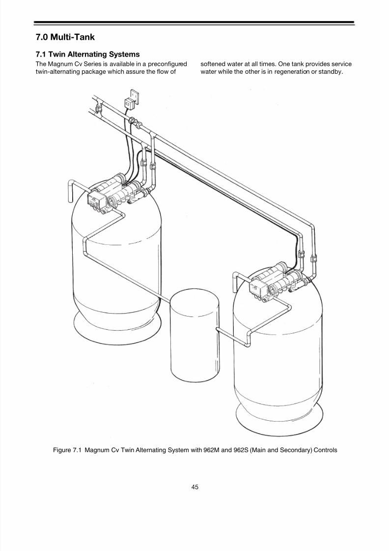
8/7/2019 1018092- Manual- Autotrol Magnum CV
http://slidepdf.com/reader/full/1018092-manual-autotrol-magnum-cv 49/8645
7.0 Multi-Tank
7.1 Twin Alternating Systems
The Magnum Cv Series is available in a preconfigured
twin-alternating package which assure the flow of
softened water at all times. One tank provides service
water while the other is in regeneration or standby.
Figure 7.1 Magnum Cv Twin Alternating System with 962M and 962S (Main and Secondary) Controls

8/7/2019 1018092- Manual- Autotrol Magnum CV
http://slidepdf.com/reader/full/1018092-manual-autotrol-magnum-cv 50/8646
Figure 7.2 Magnum Cv PLUS Twin Parallel System with 962M and 962S (Main and Secondary) Controls
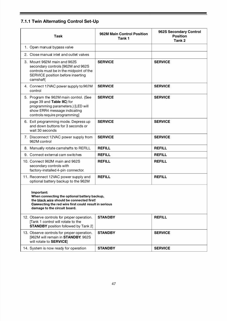
8/7/2019 1018092- Manual- Autotrol Magnum CV
http://slidepdf.com/reader/full/1018092-manual-autotrol-magnum-cv 51/8647
7.1.1 Twin Alternating Control Set-Up
Task 962M Main Control Position
Tank 1
962S Secondary Control
PositionTank 2
1. Open manual bypass valve
2. Close manual inlet and outlet valves3. Mount 962M main and 962S
secondary controls [962M and 962S
controls must be in the midpoint of the
SERVICE position before inserting
camshaft]
SERVICE SERVICE
4. Connect 12VAC power supply to 962M
control
SERVICE SERVICE
5. Program the 962M main control. (See
page 39 and Table IIC ) for
programming parameters.) [LED will
show ERR4 message indicatingcontrols require programming]
SERVICE SERVICE
6. Exit programming mode. Depress up
and down buttons for 3 seconds or
wait 30 seconds
SERVICE SERVICE
7. Disconnect 12VAC power supply from
962M control
SERVICE SERVICE
8. Manually rotate camshafts to REFILL REFILL REFILL
9. Connect external cam switches REFILL REFILL
10. Connect 962M main and 962S
secondary controls with
factory-installed 4-pin connector.
REFILL REFILL
11. Reconnect 12VAC power supply and
optional battery backup to the 962M
REFILL REFILL
12. Observe controls for proper operation.
[Tank 1 control will rotate to the
STANDBY position followed by Tank 2]
STANDBY REFILL
13. Observe controls for proper operation.
[962M will remain in STANDBY. 962S
will rotate to SERVICE]
STANDBY SERVICE
14. System is now ready for operation STANDBY SERVICE
When connecting the optional battery backup,
the black wire should be connected first!
Connecting the red wire first could result in serious
damage to the circuit board.
Important:
Con-
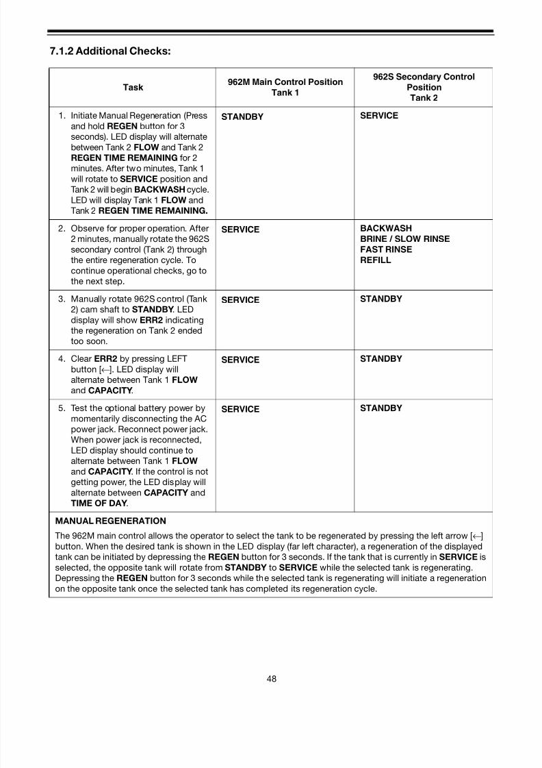
8/7/2019 1018092- Manual- Autotrol Magnum CV
http://slidepdf.com/reader/full/1018092-manual-autotrol-magnum-cv 52/8648
7.1.2 Additional Checks:
Task 962M Main Control Position
Tank 1
962S Secondary Control
PositionTank 2
1. Initiate Manual Regeneration (Press
and hold REGEN button for 3
seconds). LED display will alternatebetween Tank 2 FLOW and Tank 2
REGEN TIME REMAINING for 2
minutes. After two minutes, Tank 1
will rotate to SERVICE position and
Tank 2 will begin BACKWASH cycle.
LED will display Tank 1 FLOW and
Tank 2 REGEN TIME REMAINING.
STANDBY SERVICE
2. Observe for proper operation. After
2 minutes, manually rotate the 962S
secondary control (Tank 2) through
the entire regeneration cycle. To
continue operational checks, go tothe next step.
SERVICE BACKWASH
BRINE / SLOW RINSEFAST RINSE
REFILL
3. Manually rotate 962S control (Tank
2) cam shaft to STANDBY. LED
display will show ERR2 indicating
the regeneration on Tank 2 ended
too soon.
SERVICE STANDBY
4. Clear ERR2 by pressing LEFT
button [←]. LED display will
alternate between Tank 1 FLOW
and CAPACITY.
SERVICE STANDBY
5. Test the optional battery power by
momentarily disconnecting the AC
power jack. Reconnect power jack.
When power jack is reconnected,
LED display should continue to
alternate between Tank 1 FLOW
and CAPACITY. If the control is not
getting power, the LED display will
alternate between CAPACITY and
TIME OF DAY.
SERVICE STANDBY
MANUAL REGENERATION
The 962M main control allows the operator to select the tank to be regenerated by pressing the left arrow [←]button. When the desired tank is shown in the LED display (far left character), a regeneration of the displayed
tank can be initiated by depressing the REGEN button for 3 seconds. If the tank that is currently in SERVICE is
selected, the opposite tank will rotate from STANDBY to SERVICE while the selected tank is regenerating.
Depressing the REGEN button for 3 seconds while the selected tank is regenerating will initiate a regeneration
on the opposite tank once the selected tank has completed its regeneration cycle.

8/7/2019 1018092- Manual- Autotrol Magnum CV
http://slidepdf.com/reader/full/1018092-manual-autotrol-magnum-cv 53/8649
7.2 Twin or Triple Systems
The Magnum Cv Series Electronic Controls may be
configured as a twin parallel or triple parallel system
which assures, through an electrical interlock built into
the 962 controls, that only one unit will regenerate at a
time. Compared to a single system, the parallel system
also provides twice the available service flow rate when
both units are on line in a twin system and three timesthe available service flow rate when all three units are
on line in a triple system. When the capacity of one of
the units in a parallel system has been exhausted, the
962 control takes the unit “off-line”, regenerates the
unit, then returns the unit to “on-line” status while
preventing the other units in the system from
regeneration through an internal electrical lockout.
Figure 7.3 Magnum Cv Plus Twin Parallel Configuration
Optional SecondBrine Tank

8/7/2019 1018092- Manual- Autotrol Magnum CV
http://slidepdf.com/reader/full/1018092-manual-autotrol-magnum-cv 54/8650
Figure 7.4 Magnum Cv Plus Triple Parallel Configuration
8/7/2019 1018092- Manual- Autotrol Magnum CV
http://slidepdf.com/reader/full/1018092-manual-autotrol-magnum-cv 55/8651
7.2.1 Parallel Control Set-Up
Initial Setup
• It is advantageous to perform all control
programming prior to start up of the entire water
treatment system.
• Open the system manual bypass valve and close
all inlet and outlet valves.
• Mount all 962 controls on the valves. All controls
must indicate that they are in the REGENERATION
COMPLETE position before inserting the camshaft.
• Connect the 12VAC power supply to each control.
• Connect the interconnect cable provided with the
system to the factory installed 4 pin connector on
each control. Also connect the optional battery
back-up if provided.
• Program each 962 control in the system. See Table
IIA and Special Programming below for
programming parameters. On initial power-up, the
LED display will show an ERR4 message which
indicates that one or more of the programming
parameters are not set or is out of the allowable
range. Enter and exit the programming mode by
depressing the UP [ ↑ ] and DOWN [ ↓] buttons for
3 seconds. The programming mode can also be
exited by not pressing a button for 30 seconds.
Special Programming• Set P5-Capacity - below actual capacity - a reserve
sufficient to provide two hours of service flow is
recommended. This provides soft water when
regeneration is delayed because another unit is
already in regeneration.• Set P15-Reserve Type - “3” - fixed reserve with
immediate regeneration. This causes the control to
do an immediate regeneration when the gallons
remaining reaches zero.
• Set P16-Fixed Reserve - “0” - zero reserve. This
prevents the control from initiating a regeneration
at the programmed time, P2.
• Set all other parameters, 1 through 20, except
those identified above, as you would a standard
962 single control.
Additional Conditions
• Each 962 control requires its own 12-volt
transformer. They should all be plugged into the
same power circuit. Power loss to only one
transformer within the system may cause thesystem to malfunction.
• Each control valve should be equipped with a no
hard-water bypass cartridge.
• The flow through each control valve should be
balanced.
• The programming for all controls should be the
same.
• Three brine tanks are recommended on triple
parallel systems. This will provide adequate salt
brine for all regenerations and eliminates concern
for lack of brine strength when utilizing a single
brine tank, should back to back regenerations takeplace.

8/7/2019 1018092- Manual- Autotrol Magnum CV
http://slidepdf.com/reader/full/1018092-manual-autotrol-magnum-cv 56/8652
8.0 Start-Up Procedure
The following steps provide general guidelines for the
start-up of a water conditioning system with a Magnum
Cv Series control valve. Start up only one unit at a time.
It is advantageous to perform all 962, 962F, or 962M
programming prior to start-up.
1. Disconnect the electric power to the Magnum Cv
control. Fill the brine tank with 6 inches of water butdo not add salt to the brine tank at this time.
2. The manual inlet and outlet valves should remain
closed with the manual bypass valve open.
3. Remove the cam cover to reveal camshaft. Verify
that the correct cam is inserted all the way into the
control. Access to the camshaft is required to
manually index the control valve to the desired
cycles of operation.
4. Advance the control to the Backwash position by
turning the camshaft COUNTERCLOCKWISE.
(Pilot flappers #2, #3, and #5 are OPEN.) THEPROPER SIZE DRAIN LINE FLOW CONTROL FOR
THE SYSTEM BEING STARTED UP MUST BE
INSTALLED IN THE DRAIN LINE AS CLOSE TO
THE CONTROL VALVE AS POSSIBLE.
5. Slowly open the manual inlet valve. Water will begin
to flow to drain. Water pressure must build to
approximately 20 pounds per square inch (psi)
(137 kPa) in the control valve and tank for the
pilot/diaphragm valve system to operate properly.
Continue to open the manual inlet valve slowly.
(Note: large capacity systems will flow an extremely
large amount of water to drain while pressure
builds within the system). A definite change in the
flow to drain and sound, as the diaphragm
cartridges shift into position, will indicate that
adequate pressure has been built up in the system.
When the control valve does shift into the
backwash position, the air in the tank will be
pushed out through the drain line. Monitor the drain
line closely during this time. If backwash flow
during start-up is too high, resin or mineral could
be pushed out of the tank through the drain line.
The manual inlet valve can be closed slightly to
prevent resin loss, however, a minimum pressure
must be maintained within the system forcontinued pilot/diaphragm valve operation.
Note: There are times when the system has a difficult
time building enough pressure for proper
pilot/diaphragm valve operation, such as low pressure
applications and larger pipe sizes. If water flows to
drain in all cycles and does not shut off in service,
typically, either the inlet valve is not open far enough or
the drain line flow control has not been installed in the
drain line.
6. After all the air has been purged from the tank,
allow the backwash water to flow to drain until
clear.
7. Advance the control camshaft to the Brine/ Rinse
position by rotating the camshaft
COUNTERCLOCKWISE. (Pilot flappers #B1, #B2,
#1, #3, and #5 are OPEN on softeners only--thiscycle is skipped on 3-cycle filters.) The water flow
to drain should reduce significantly and brine draw
should be observed. Reference the Performance
Data and Charts section.
8. Advance the control to the Fast Rinse position by
turning the camshaft COUNTERCLOCKWISE.
(Pilot flappers #1, #3, #4, and #5 are OPEN.) The
water flow to drain should increase significantly, to
approximately the same as the backwash flow.
9. Advance the control valve to the Refill position by
rotating the camshaft COUNTERCLOCKWISE.
(Pilot Flappers #B1, #B2, #1, #2, and #4 are OPEN.
Pilot Flapper #3 on Twin Alternating systems is also
OPEN. This cycle is skipped on 3-cycle filters). A
flow of water should be filling the brine tank. The
brine tank can be filled to the proper level if the
water height is known. There should be NO water
flow to drain. Reference the Performance Data
and Charts section.
10. Advance the control valve to a position just before
the Regeneration Complete position (softener) or
the Backwash Complete position (filter). Connect
electrical power to the controller. Allow the control
to drive the camshaft to the home position. Note:See the special section 7.1.1 for Twin Alternating
control set-up.
11. Open the manual outlet valve completely and close
the manual bypass valve. Perform any 942 or 942F
control programming if necessary. Check the
effluent for soft or iron-free water. Add salt to the
brine tank.

8/7/2019 1018092- Manual- Autotrol Magnum CV
http://slidepdf.com/reader/full/1018092-manual-autotrol-magnum-cv 57/86

8/7/2019 1018092- Manual- Autotrol Magnum CV
http://slidepdf.com/reader/full/1018092-manual-autotrol-magnum-cv 58/86
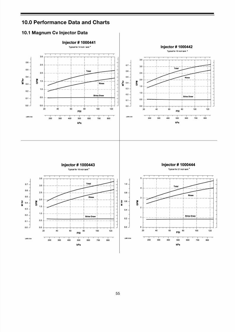
8/7/2019 1018092- Manual- Autotrol Magnum CV
http://slidepdf.com/reader/full/1018092-manual-autotrol-magnum-cv 59/8655
10.0 Performance Data and Charts
10.1 Magnum Cv Injector Data
*
*
*
*

8/7/2019 1018092- Manual- Autotrol Magnum CV
http://slidepdf.com/reader/full/1018092-manual-autotrol-magnum-cv 60/8656
*
*
*
* Brine draw and Rinse rates on empty tank
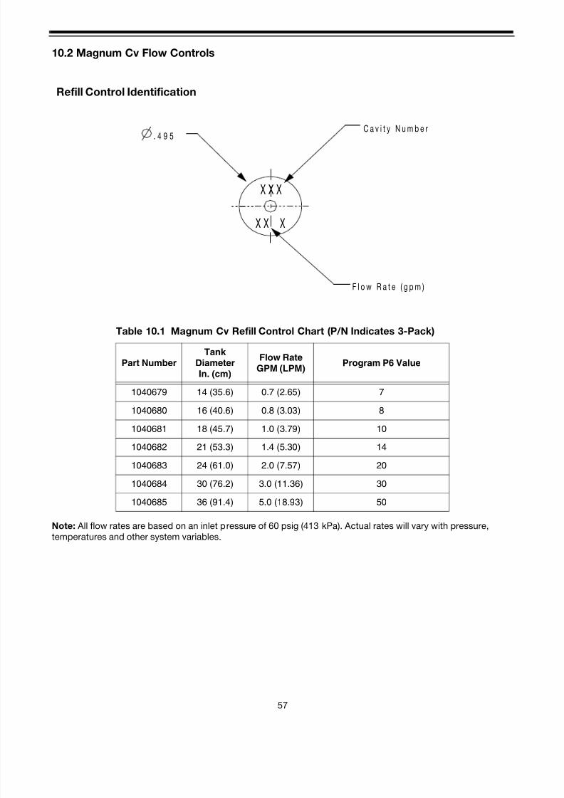
8/7/2019 1018092- Manual- Autotrol Magnum CV
http://slidepdf.com/reader/full/1018092-manual-autotrol-magnum-cv 61/8657
10.2 Magnum Cv Flow Controls
Note: All flow rates are based on an inlet pressure of 60 psig (413 kPa). Actual rates will vary with pressure,
temperatures and other system variables.
X X
X X X
X
. 4 9 5
C a v i t y N u m b e r
F l o w R a t e ( g p m )
Refill Control Identification
Table 10.1 Magnum Cv Refill Control Chart (P/N Indicates 3-Pack)
Part NumberTank
DiameterIn. (cm)
Flow RateGPM (LPM)
Program P6 Value
1040679 14 (35.6) 0.7 (2.65) 7
1040680 16 (40.6) 0.8 (3.03) 8
1040681 18 (45.7) 1.0 (3.79) 10
1040682 21 (53.3) 1.4 (5.30) 14
1040683 24 (61.0) 2.0 (7.57) 20
1040684 30 (76.2) 3.0 (11.36) 30
1040685 36 (91.4) 5.0 (18.93) 50
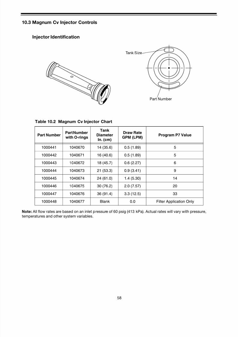
8/7/2019 1018092- Manual- Autotrol Magnum CV
http://slidepdf.com/reader/full/1018092-manual-autotrol-magnum-cv 62/8658
10.3 Magnum Cv Injector Controls
Note: All flow rates are based on an inlet pressure of 60 psig (413 kPa). Actual rates will vary with pressure,
temperatures and other system variables.
Injector Identification
Tank Size
Part Number
Table 10.2 Magnum Cv Injector Chart
Part NumberPart Number
with O-rings
Tank
DiameterIn. (cm)
Draw Rate
GPM (LPM)Program P7 Value
1000441 1040670 14 (35.6) 0.5 (1.89) 5
1000442 1040671 16 (40.6) 0.5 (1.89) 5
1000443 1040672 18 (45.7) 0.6 (2.27) 6
1000444 1040673 21 (53.3) 0.9 (3.41) 9
1000445 1040674 24 (61.0) 1.4 (5.30) 14
1000446 1040675 30 (76.2) 2.0 (7.57) 20
1000447 1040676 36 (91.4) 3.3 (12.5) 33
1000448 1040677 Blank 0.0 Filter Application Only
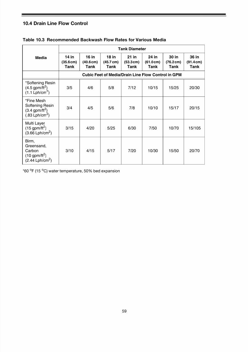
8/7/2019 1018092- Manual- Autotrol Magnum CV
http://slidepdf.com/reader/full/1018092-manual-autotrol-magnum-cv 63/8659
10.4 Drain Line Flow Control
*60 oF (15 oC) water temperature, 50% bed expansion
Table 10.3 Recommended Backwash Flow Rates for Various Media
Media
Tank Diameter
14 in
(35.6 cm) Tank
16 in
(40.6 cm) Tank
18 in
(45.7 cm) Tank
21 in
(53.3 cm) Tank
24 in
(61.0 cm) Tank
30 in
(76.2 cm) Tank
36 in
(91.4 cm) Tank
Cubic Feet of Media/Drain Line Flow Control in GPM
*Softening Resin
(4.5 gpm/ft2)(1.1 Lph/cm2)
3/5 4/6 5/8 7/12 10/15 15/25 20/30
*Fine MeshSoftening Resin
(3.4 gpm/ft2)(.83 Lph/cm2)
3/4 4/5 5/6 7/8 10/10 15/17 20/15
Multi Layer(15 gpm/ft2)(3.66 Lph/cm2)
3/15 4/20 5/25 6/30 7/50 10/70 15/105
Birm,Greensand,
Carbon(10 gpm/ft2)(2.44 Lph/cm2)
3/10 4/15 5/17 7/20 10/30 15/50 20/70
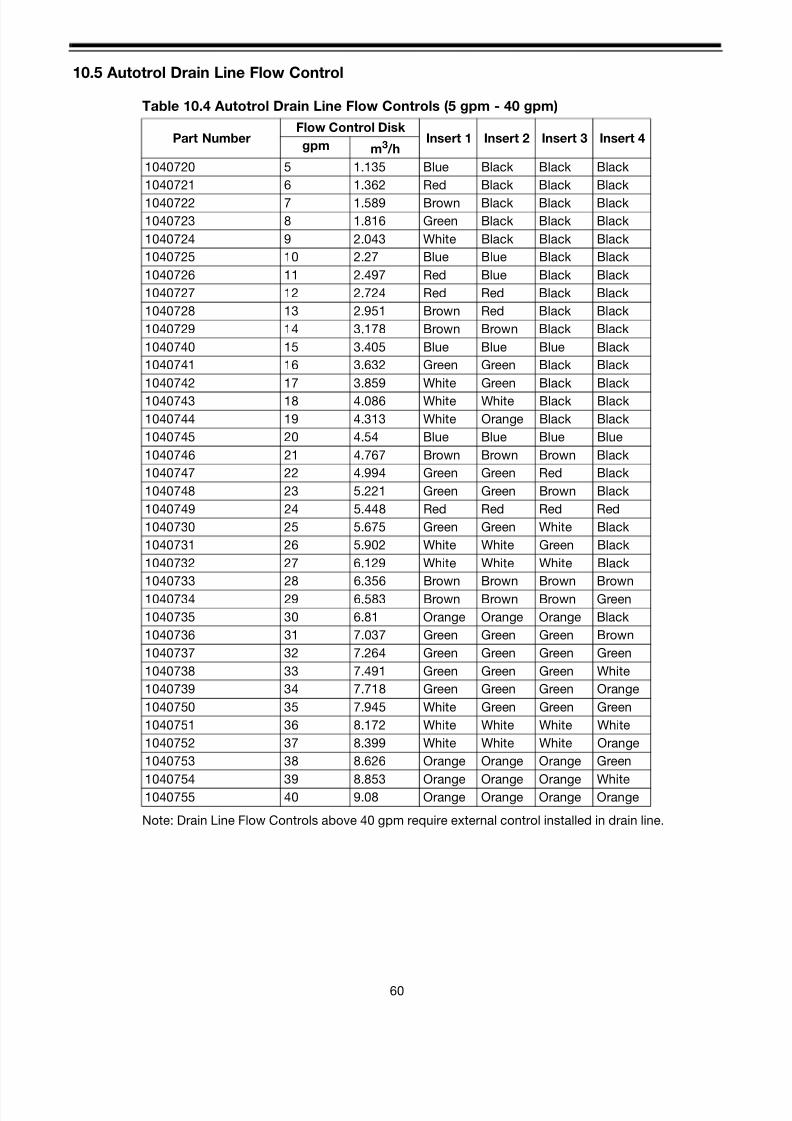
8/7/2019 1018092- Manual- Autotrol Magnum CV
http://slidepdf.com/reader/full/1018092-manual-autotrol-magnum-cv 64/8660
10.5 Autotrol Drain Line Flow Control
Table 10.4 Autotrol Drain Line Flow Controls (5 gpm - 40 gpm)
Note: Drain Line Flow Controls above 40 gpm require external control installed in drain line.
Part NumberFlow Control Disk
Insert 1 Insert 2 Insert 3 Insert 4gpm m3 /h
1040720 5 1.135 Blue Black Black Black
1040721 6 1.362 Red Black Black Black
1040722 7 1.589 Brown Black Black Black
1040723 8 1.816 Green Black Black Black
1040724 9 2.043 White Black Black Black
1040725 10 2.27 Blue Blue Black Black
1040726 11 2.497 Red Blue Black Black
1040727 12 2.724 Red Red Black Black
1040728 13 2.951 Brown Red Black Black
1040729 14 3.178 Brown Brown Black Black
1040740 15 3.405 Blue Blue Blue Black
1040741 16 3.632 Green Green Black Black
1040742 17 3.859 White Green Black Black
1040743 18 4.086 White White Black Black
1040744 19 4.313 White Orange Black Black
1040745 20 4.54 Blue Blue Blue Blue
1040746 21 4.767 Brown Brown Brown Black
1040747 22 4.994 Green Green Red Black
1040748 23 5.221 Green Green Brown Black
1040749 24 5.448 Red Red Red Red
1040730 25 5.675 Green Green White Black
1040731 26 5.902 White White Green Black
1040732 27 6.129 White White White Black
1040733 28 6.356 Brown Brown Brown Brown
1040734 29 6.583 Brown Brown Brown Green
1040735 30 6.81 Orange Orange Orange Black
1040736 31 7.037 Green Green Green Brown
1040737 32 7.264 Green Green Green Green
1040738 33 7.491 Green Green Green White
1040739 34 7.718 Green Green Green Orange
1040750 35 7.945 White Green Green Green
1040751 36 8.172 White White White White
1040752 37 8.399 White White White Orange
1040753 38 8.626 Orange Orange Orange Green
1040754 39 8.853 Orange Orange Orange White1040755 40 9.08 Orange Orange Orange Orange

8/7/2019 1018092- Manual- Autotrol Magnum CV
http://slidepdf.com/reader/full/1018092-manual-autotrol-magnum-cv 65/8661
11.0 Wiring Diagrams
11.1 Model 962 Series Electronic Control
Remote Regeneration Initiation
NOTE: The 962 Series Electronic Control is not recommended for pressure differential initiation or sequential
regeneration of multiple tank systems. Please consult Osmonics for these applications.
SOURCE POWER ..... 2mA@(FROM 962, 962M) 12VDC
PUSH BUTTON SWITCHOR ALTERNATE SWITCHOPERATION
MINIMUM SIGNAL LENGTH... 3 SECONDS
CONTROL SOURCEPOWER .2mA @ 12 VAC(FROM 962, 962MTRANSFORMER)
INITIATE BY PUSH BUTTONSWITCH OR ALTERNATESWITCH OPERATION - DRYCONTACT CLOSURE
MINIMUM SIGNAL LENGTH0.3 SECONDS
MAXIMUM SIGNAL LENGTH45 SECONDS

8/7/2019 1018092- Manual- Autotrol Magnum CV
http://slidepdf.com/reader/full/1018092-manual-autotrol-magnum-cv 66/8662
11.2 Model 952 Twin Series Impulse Control
11.3 Model 952QC Impulse Control
Motor952 Switch
C NO NC
WhiteL2
RedStart
BlackL1
MOTOR
MOTOR LEADS
YELLOW / WHITE
ISOLATION SIGNAL
GROUND NOT USED IN
THIS APPLICATION
WHITE
RED
RED
C NO NC
BLACK
QC CABLE
FEEDBACK SIGNAL
WIRES / CONNECTORS
Y E L L O W
R E D
B L A C K
R E D
B L A C K
W H I T E
G R E E N / Y E L L O W
BLACK WHITE RED
LEGEND
YELLOW ISOLATION
RED START REGENERATION
BLACK HOT
WHITE NEUTRAL
GRN/YEL GROUND
FEEDBACK CABLE
RED AND BLACK
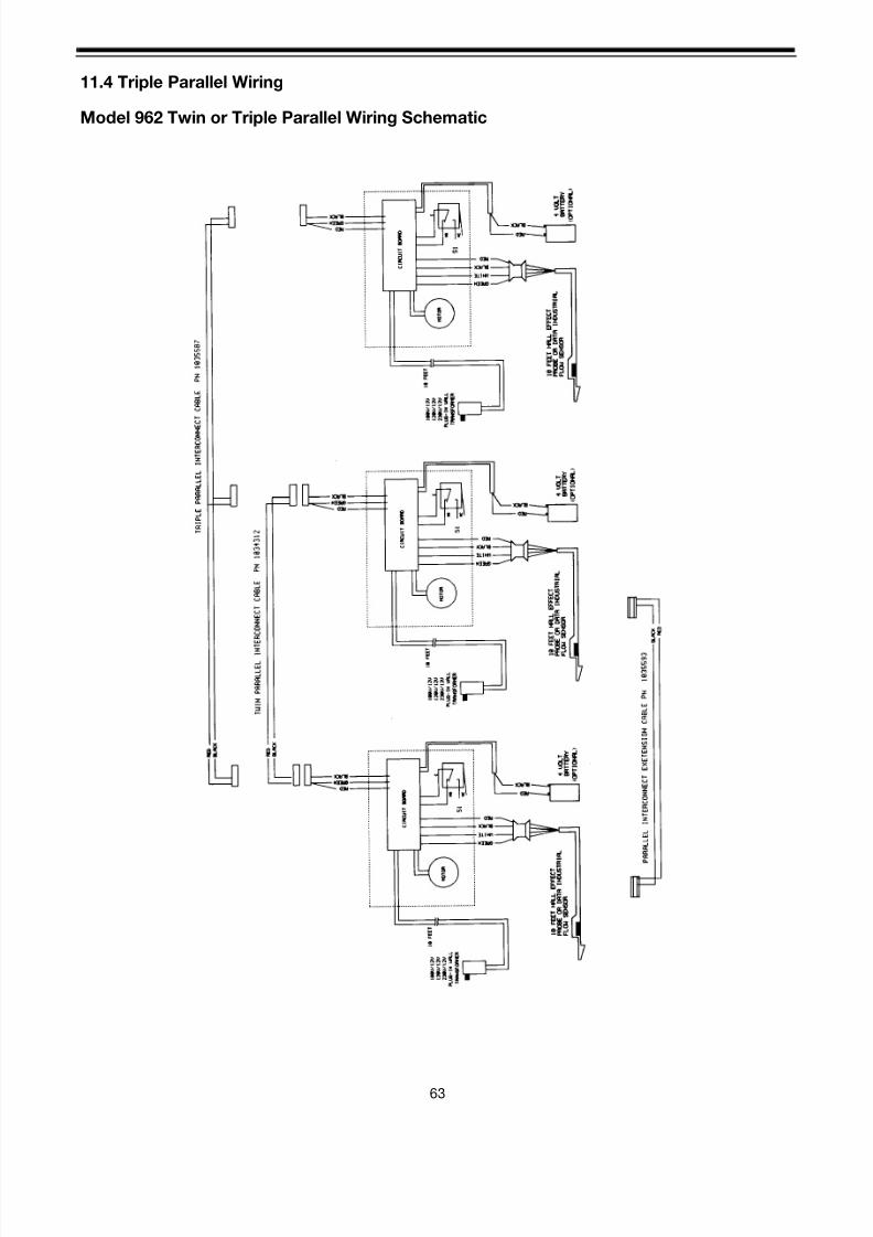
8/7/2019 1018092- Manual- Autotrol Magnum CV
http://slidepdf.com/reader/full/1018092-manual-autotrol-magnum-cv 67/86

8/7/2019 1018092- Manual- Autotrol Magnum CV
http://slidepdf.com/reader/full/1018092-manual-autotrol-magnum-cv 68/8664
11.5 Model 962 Twin Alternating SystemMain/Secondary Wiring Schematic
M O T O
R
M O T O R
1 0 F E E T
1 0 F E E T
S I –
C L O S E D I N S E R V I C E O R S T A N D B Y ,
L O C A T E D I N S I D E T I M E R .
S 2 –
O P E N I N S E R V I C E O R S T A N D B Y , L O
C A T E D I N S I D E T I M E R .
S 3 ,
S 4 –
C L O S E D I N S T A N D B Y ,
L O C A T E D
O U T S I D E T I M E R A N D A C T I V A T E D B Y C A M .
A L L S W I T C H E S S H O W N I N
S E R V I C E / S T A N D B Y P O S
I T I O N .
C
C
C
C
N O
N O
N O
N O
N C
N C
N C
N C
S 1
S 3
S 2
9 6 2 S
9 6 2 M
S 4
4 V O L T
B A T T E R Y
( O P T I O N A L )
1 0 F E E T W A L L E F F E C T
P R O B E O R D A T A I N D U S T R I A L
F L O W S
E N S O R
1 0 0 V / 1 2 V
1 2 0 V / 1 2 V
2 3 0 V / 1 2 V
P L U G - I N
W A L L
T R A N S F O R M E R
C I R C U I T B O A R D
B L A C K
B L A C K
R E D
R E D
B L A C K
R E D
W H I T E
G R E E N
B L A C K
B L A C K
R E D
R E D
G R E E N
G R E E N
W H I T E
I N T E R F A C E
C O N N E C T O R

8/7/2019 1018092- Manual- Autotrol Magnum CV
http://slidepdf.com/reader/full/1018092-manual-autotrol-magnum-cv 69/8665
12.0 Assembly Drawings and Parts List
Magnum Cv Controls
12.1 Manual Controls
Figure 12.1 Magnum Cv 942MAN Figure 12.2 Magnum Cv 942FMAN
Table 12.1 942 Manual Control Configurations
Part Number Description
1034398 Manual Control/942Man Softener/English
1034399 Manual Control/942FMan Filter/English

8/7/2019 1018092- Manual- Autotrol Magnum CV
http://slidepdf.com/reader/full/1018092-manual-autotrol-magnum-cv 70/8666
12.2 Mechanical Timeclock Controls
Figure 12.3 Magnum Cv 942 (Softener) Figure 12.4 Magnum Cv 942F (Filter)
Table 12.2 Mechanical Timeclock 12V/50 Hz Configurations
Part Number Description
1046850 Timeclock Control/942 Softener/7 Day/24 Hour/12 VAC/50 Hz
1046851 Timeclock Control/942 Softener/12 Day/24 Hour/12 VAC/50 Hz
1046852 Timeclock Control/942F Filter/7 Day/24 Hour/12 VAC/50 Hz
1046853 Timeclock Control/942F Filter/12 Day/24 Hour/12 VAC/50 Hz
Table 12.3 942 Mechanical Timeclock 12V/60 Hz Configurations
Part Number Description
1046868 Timeclock Control/942 Softener/7 Day/24 Hour/12 VAC/60 Hz
1046869 Timeclock Control/942 Softener/12 Day/24 Hour/12 VAC/60 Hz
1046870 Timeclock Control/942F Filter/7 Day/24 Hour/12 VAC/60 Hz
1046871 Timeclock Control/942F Filter/12 Day/24 Hour/12 VAC/60 Hz
Table 12.4 942 Mechanical Timeclock 120V/60 Hz Configurations
Part Number Description
1046317 Timeclock Control/942 Softener/7 Day/24 Hour/120 VAC/60 Hz
1046318 Timeclock Control/942 Softener/12 Day/24 Hour/120 VAC/60 Hz
1046319 Timeclock Control/942F Filter/7 Day/24 Hour/120 VAC/60 Hz
1046320 Timeclock Control/942F Filter/12 Day/24 Hour/120 VAC/60 Hz
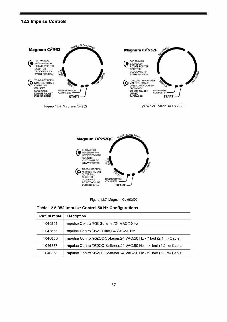
8/7/2019 1018092- Manual- Autotrol Magnum CV
http://slidepdf.com/reader/full/1018092-manual-autotrol-magnum-cv 71/8667
12.3 Impulse Controls
Figure 12.5 Magnum Cv 952 Figure 12.6 Magnum Cv 952F
Figure 12.7 Magnum Cv 952QC
Table 12.5 952 Impulse Control 50 Hz Configurations
Part Number Description
1046854 Impulse Control/952 Softener/24 VAC/50 Hz
1046855 Impulse Control/952F Filter/24 VAC/50 Hz
1046856 Impulse Control/952QC Softener/24 VAC/50 Hz - 7 foot (2.1 m) Cable
1046857 Impulse Control/952QC Softener/24 VAC/50 Hz - 14 foot (4.2 m) Cable
1046858 Impulse Control/952QC Softener/24 VAC/50 Hz - 21 foot (6.3 m) Cable
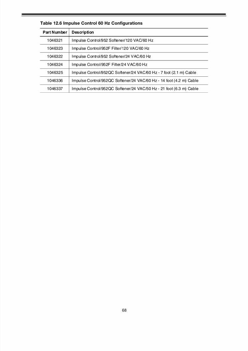
8/7/2019 1018092- Manual- Autotrol Magnum CV
http://slidepdf.com/reader/full/1018092-manual-autotrol-magnum-cv 72/8668
Table 12.6 Impulse Control 60 Hz Configurations
Part Number Description
1046321 Impulse Control/952 Softener/120 VAC/60 Hz
1046323 Impulse Control/952F Filter/120 VAC/60 Hz
1046322 Impulse Control/952 Softener/24 VAC/60 Hz
1046324 Impulse Control/952F Filter/24 VAC/60 Hz
1046325 Impulse Control/952QC Softener/24 VAC/60 Hz - 7 foot (2.1 m) Cable
1046336 Impulse Control/952QC Softener/24 VAC/60 Hz - 14 foot (4.2 m) Cable
1046337 Impulse Control/952QC Softener/24 VAC/50 Hz - 21 foot (6.3 m) Cable
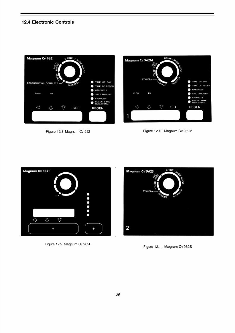
8/7/2019 1018092- Manual- Autotrol Magnum CV
http://slidepdf.com/reader/full/1018092-manual-autotrol-magnum-cv 73/8669
12.4 Electronic Controls
Figure 12.8 Magnum Cv 962
Figure 12.9 Magnum Cv 962F
Figure 12.10 Magnum Cv 962M
Figure 12.11 Magnum Cv 962S
TIME OF BACKWASH
SET VALUE TO 10
SET VALUE TO 5
CAPACITY
REMAINING
SET BACKWASH
BACKWASH
FLOW PM
COMPLETE
BACKWASH TIME
TIME OF DAY
B AC K W A S
H
P U R G E
TM

8/7/2019 1018092- Manual- Autotrol Magnum CV
http://slidepdf.com/reader/full/1018092-manual-autotrol-magnum-cv 74/8670
Figure 12.12 Magnum Cv 962TC Figure 12.13 Magnum Cv 962FTC
* Battery Not Included.
* Battery Not Included.
TC
TIME OF BACKWASH
SET VALUE TO 10
SET VALUE TO 5
CAPACITY
REMAINING
SET BACKWASH
BACKWASH
FLOW PM
COMPLETE
BACKWASH TIME
TIME OF DAY
B AC K W A S
H
P U R G E
TM
Magnum Cv 962FTC
Table 12.7 962 Electronic Control 12V/50 Hz Configurations
Part Number Description
1046860 Electronic Control/962 Softener/Battery Backup/12 VAC/50 Hz*
1046862 Electronic Control/962M Main/Battery Backup/12 VAC/50 Hz*
1046863 Electronic Control/962S Secondary/12 VAC/50 Hz
1046873 Electronic Control/962F Filter/Battery Backup/12 VAC/50 Hz*
Table 12.8 962 Electronic Control 12 V/ 60 Hz Configurations
Part Number Description
1046327 Electronic Control/962 Softener/Battery Backup/12 VAC/60 Hz*
1046329 Electronic Control/962M Main/Battery Backup/12 VAC/60 Hz*
1046330 Electronic Control/962S Secondary/12 VAC/60 Hz
1046867 Electronic Control/962F Filter/Battery Backup/12 VAC/60 Hz*
1053846Electronic Time Clock Control/962TC Softener/Battery Backup/12 VAC/60
Hz
1053847 Electronic Time Clock Control/962FTC Filter/Battery Backup/12 VAC/60 Hz

8/7/2019 1018092- Manual- Autotrol Magnum CV
http://slidepdf.com/reader/full/1018092-manual-autotrol-magnum-cv 75/8671
Table 12.9 Transformers
Part Number Description
1000810 12 V Wall Mount Transformer/100 VAC/50/60 Hz/150 mA/Japanese Plug
1000811 12 V Wall Mount Transformer/120 VAC/60 Hz/150 mA/North American Plug
1000812 12 V Wall Mount Transformer/240 VAC/50 Hz/150 mA/Australian/Arentine Plug
1000813 12 V Wall Mount Transformer/240 VAC/50 Hz/150 mA/British Plug
1000814 12 V Wall Mount Transformer/230 VAC/50 Hz/150 mA/European/Italian Plug
Table 12.10 Miscellaneous Parts
Part Number Description
1075768 Battery
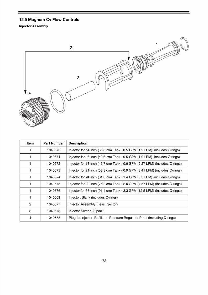
8/7/2019 1018092- Manual- Autotrol Magnum CV
http://slidepdf.com/reader/full/1018092-manual-autotrol-magnum-cv 76/8672
12.5 Magnum Cv Flow Controls
Injector Assembly
1
3
4
2
Item Part Number Description
1 1040670 Injector for 14-inch (35.6 cm) Tank - 0.5 GPM (1.9 LPM) (includes O-rings)
1 1040671 Injector for 16-inch (40.6 cm) Tank - 0.5 GPM (1.9 LPM) (includes O-rings)
1 1040672 Injector for 18-inch (45.7 cm) Tank - 0.6 GPM (2.27 LPM) (includes O-rings)
1 1040673 Injector for 21-inch (53.3 cm) Tank - 0.9 GPM (3.41 LPM) (includes O-rings)
1 1040674 Injector for 24-inch (61.0 cm) Tank - 1.4 GPM (5.3 LPM) (includes O-rings)
1 1040675 Injector for 30-inch (76.2 cm) Tank - 2.0 GPM (7.57 LPM) (includes O-rings)
1 1040676 Injector for 36-inch (91.4 cm) Tank - 3.3 GPM (12.5 LPM) (includes O-rings)
1 1040669 Injector, Blank (includes O-rings)
2 1040677 Injector Assembly (Less Injector)
3 1040678 Injector Screen (3 pack)
4 1040688 Plug for Injector, Refill and Pressure Regulator Ports (including O-rings)
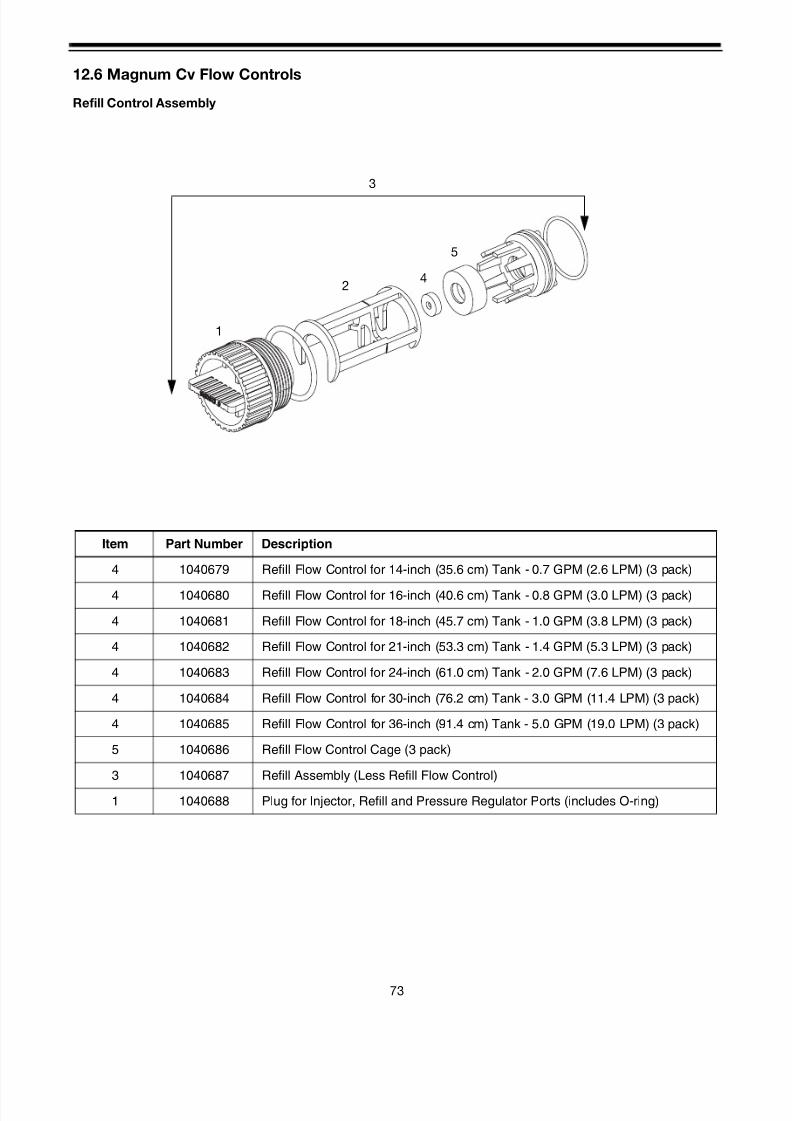
8/7/2019 1018092- Manual- Autotrol Magnum CV
http://slidepdf.com/reader/full/1018092-manual-autotrol-magnum-cv 77/8673
12.6 Magnum Cv Flow Controls
Refill Control Assembly
5
42
1
3
Item Part Number Description
4 1040679 Refill Flow Control for 14-inch (35.6 cm) Tank - 0.7 GPM (2.6 LPM) (3 pack)
4 1040680 Refill Flow Control for 16-inch (40.6 cm) Tank - 0.8 GPM (3.0 LPM) (3 pack)
4 1040681 Refill Flow Control for 18-inch (45.7 cm) Tank - 1.0 GPM (3.8 LPM) (3 pack)
4 1040682 Refill Flow Control for 21-inch (53.3 cm) Tank - 1.4 GPM (5.3 LPM) (3 pack)
4 1040683 Refill Flow Control for 24-inch (61.0 cm) Tank - 2.0 GPM (7.6 LPM) (3 pack)
4 1040684 Refill Flow Control for 30-inch (76.2 cm) Tank - 3.0 GPM (11.4 LPM) (3 pack)
4 1040685 Refill Flow Control for 36-inch (91.4 cm) Tank - 5.0 GPM (19.0 LPM) (3 pack)
5 1040686 Refill Flow Control Cage (3 pack)
3 1040687 Refill Assembly (Less Refill Flow Control)
1 1040688 Plug for Injector, Refill and Pressure Regulator Ports (includes O-ring)

8/7/2019 1018092- Manual- Autotrol Magnum CV
http://slidepdf.com/reader/full/1018092-manual-autotrol-magnum-cv 78/8674
12.6 Magnum Cv Flow Controls
2-Inch Turbine Assembly
1
2
3
Item Part Number Description
1 1000074 Insert, Corner 2-inch
2 1232965 Assembly, Turbine 2-inch Elbow
3 1000318 Assembly, Plug
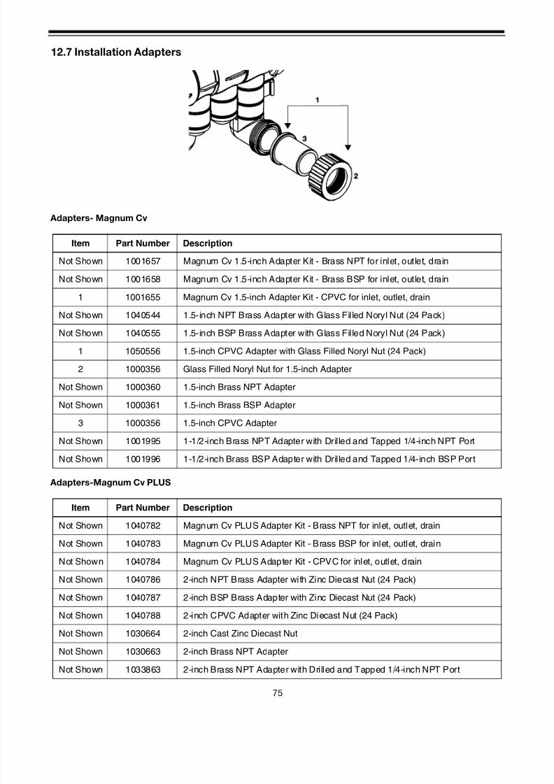
8/7/2019 1018092- Manual- Autotrol Magnum CV
http://slidepdf.com/reader/full/1018092-manual-autotrol-magnum-cv 79/8675
12.7 Installation Adapters
Adapters- Magnum Cv
Adapters-Magnum Cv PLUS
Item Part Number Description
Not Shown 1001657 Magnum Cv 1.5-inch Adapter Kit - Brass NPT for inlet, outlet, drain
Not Shown 1001658 Magnum Cv 1.5-inch Adapter Kit - Brass BSP for inlet, outlet, drain
1 1001655 Magnum Cv 1.5-inch Adapter Kit - CPVC for inlet, outlet, drain
Not Shown 1040544 1.5-inch NPT Brass Adapter with Glass Filled Noryl Nut (24 Pack)
Not Shown 1040555 1.5-inch BSP Brass Adapter with Glass Filled Noryl Nut (24 Pack)
1 1050556 1.5-inch CPVC Adapter with Glass Filled Noryl Nut (24 Pack)
2 1000356 Glass Filled Noryl Nut for 1.5-inch Adapter
Not Shown 1000360 1.5-inch Brass NPT Adapter
Not Shown 1000361 1.5-inch Brass BSP Adapter
3 1000356 1.5-inch CPVC Adapter
Not Shown 1001995 1-1/2-inch Brass NPT Adapter with Drilled and Tapped 1/4-inch NPT Port
Not Shown 1001996 1-1/2-inch Brass BSP Adapter with Drilled and Tapped 1/4-inch BSP Port
Item Part Number Description
Not Shown 1040782 Magnum Cv PLUS Adapter Kit - Brass NPT for inlet, outlet, drain
Not Shown 1040783 Magnum Cv PLUS Adapter Kit - Brass BSP for inlet, outlet, drain
Not Shown 1040784 Magnum Cv PLUS Adapter Kit - CPVC for inlet, outlet, drain
Not Shown 1040786 2-inch NPT Brass Adapter with Zinc Diecast Nut (24 Pack)
Not Shown 1040787 2-inch BSP Brass Adapter with Zinc Diecast Nut (24 Pack)
Not Shown 1040788 2-inch CPVC Adapter with Zinc Diecast Nut (24 Pack)
Not Shown 1030664 2-inch Cast Zinc Diecast Nut
Not Shown 1030663 2-inch Brass NPT Adapter
Not Shown 1033863 2-inch Brass NPT Adapter with Drilled and Tapped 1/4-inch NPT Port

8/7/2019 1018092- Manual- Autotrol Magnum CV
http://slidepdf.com/reader/full/1018092-manual-autotrol-magnum-cv 80/8676
Not Shown 1030665 2-inch Brass BSP Adapter
Not Shown 1033864 2-inch Brass BSP Adapter with Drilled and Tapped 1/4-inch BSP Port
Not Shown 1030666 2-inch CPVC Adapter
Not Shown 1030667 63-mm Metric PVC Adapter
Not Shown 1002906 1.5-inch to 2-inch Brass Bell Reducer Coupling
Not Shown 1010160 1.5-inch Adapter O-Ring
Not Shown 1010165 2.0-inch Adapter O-Ring
Item Part Number Description
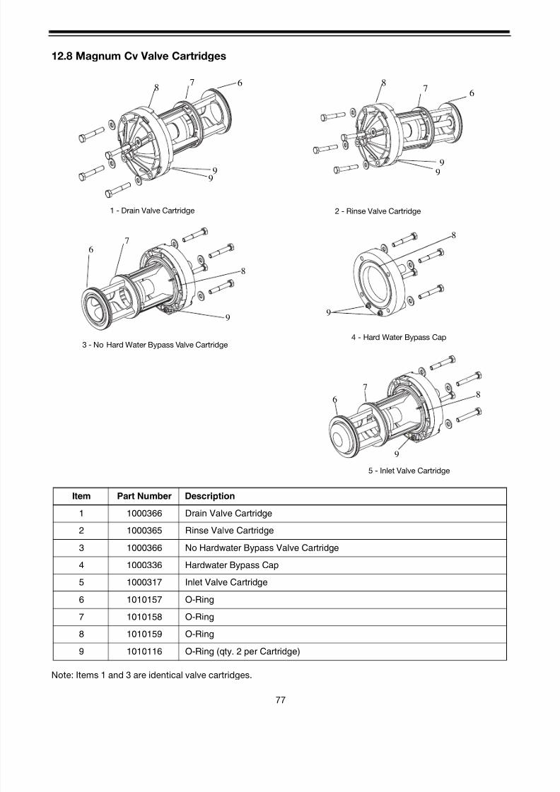
8/7/2019 1018092- Manual- Autotrol Magnum CV
http://slidepdf.com/reader/full/1018092-manual-autotrol-magnum-cv 81/8677
12.8 Magnum Cv Valve Cartridges
Note: Items 1 and 3 are identical valve cartridges.
Item Part Number Description
1 1000366 Drain Valve Cartridge
2 1000365 Rinse Valve Cartridge
3 1000366 No Hardwater Bypass Valve Cartridge
4 1000336 Hardwater Bypass Cap
5 1000317 Inlet Valve Cartridge
6 1010157 O-Ring
7 1010158 O-Ring
8 1010159 O-Ring
9 1010116 O-Ring (qty. 2 per Cartridge)
87 6
99
6
7
8
9
6
7
9
8
8
9
1 - Drain Valve Cartridge
3 - No Hard Water Bypass Valve Cartridge
5 - Inlet Valve Cartridge
4 - Hard Water Bypass Cap
2 - Rinse Valve Cartridge
87
6
9
9

8/7/2019 1018092- Manual- Autotrol Magnum CV
http://slidepdf.com/reader/full/1018092-manual-autotrol-magnum-cv 82/8678
12.9 Cam and Pilot Valve Assembly
Black
Item Part Number Description
1 1000535 Camshaft Assembly - 5 Cycle Softener
2 1000538 Camshaft Assembly - 3 Cycle Filter
3* 1001751 Camshaft Assembly - Twin Alternating
4 1000341 Camshaft
5 1000461 Brine Cam - Co-current 5 Cycle Softener (Maroon)
6 1000462 Universal Cam Switcher (Black)
7 1000464 Pilot Cam - Co-current 5 Cycle Softener #1 (Maroon)
8 1000465 Pilot Cam - Co-current 5 Cycle Softener #2 (Blue)
9 1000466 Pilot Cam - Co-current 5 Cycle Softener #3 (Green)
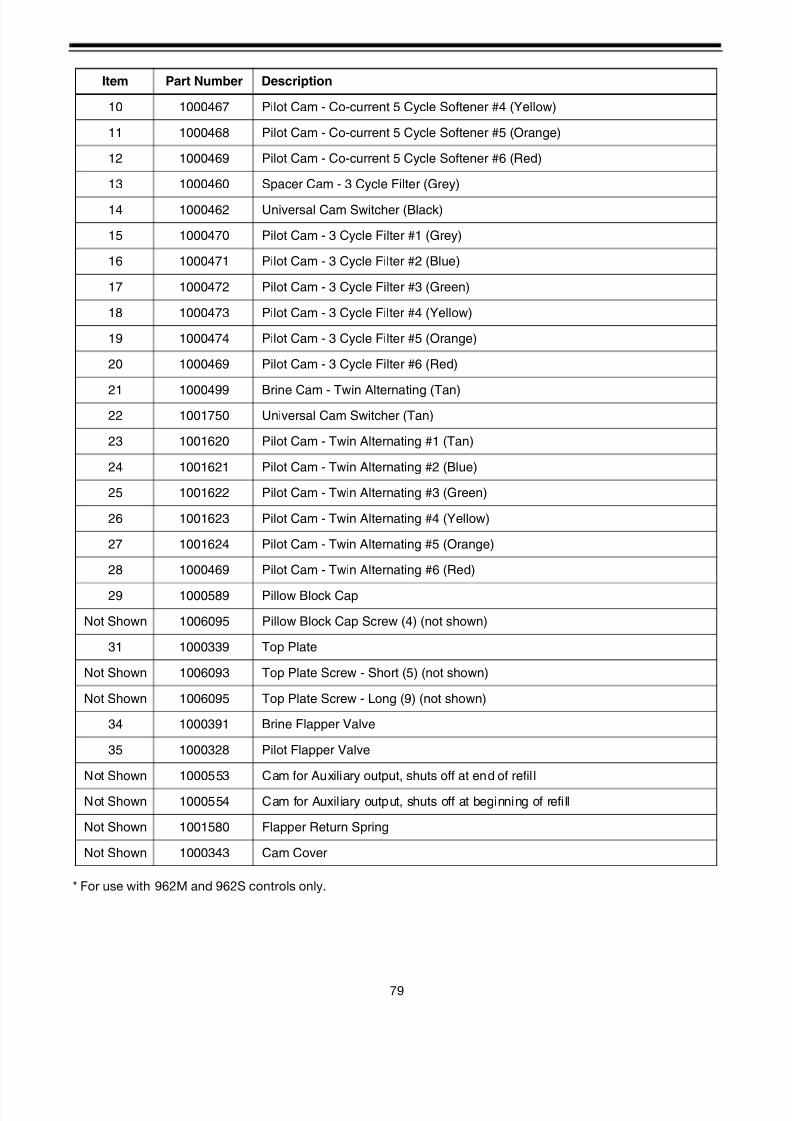
8/7/2019 1018092- Manual- Autotrol Magnum CV
http://slidepdf.com/reader/full/1018092-manual-autotrol-magnum-cv 83/8679
* For use with 962M and 962S controls only.
10 1000467 Pilot Cam - Co-current 5 Cycle Softener #4 (Yellow)
11 1000468 Pilot Cam - Co-current 5 Cycle Softener #5 (Orange)
12 1000469 Pilot Cam - Co-current 5 Cycle Softener #6 (Red)
13 1000460 Spacer Cam - 3 Cycle Filter (Grey)
14 1000462 Universal Cam Switcher (Black)
15 1000470 Pilot Cam - 3 Cycle Filter #1 (Grey)
16 1000471 Pilot Cam - 3 Cycle Filter #2 (Blue)
17 1000472 Pilot Cam - 3 Cycle Filter #3 (Green)
18 1000473 Pilot Cam - 3 Cycle Filter #4 (Yellow)
19 1000474 Pilot Cam - 3 Cycle Filter #5 (Orange)
20 1000469 Pilot Cam - 3 Cycle Filter #6 (Red)
21 1000499 Brine Cam - Twin Alternating (Tan)
22 1001750 Universal Cam Switcher (Tan)
23 1001620 Pilot Cam - Twin Alternating #1 (Tan)
24 1001621 Pilot Cam - Twin Alternating #2 (Blue)
25 1001622 Pilot Cam - Twin Alternating #3 (Green)
26 1001623 Pilot Cam - Twin Alternating #4 (Yellow)
27 1001624 Pilot Cam - Twin Alternating #5 (Orange)
28 1000469 Pilot Cam - Twin Alternating #6 (Red)
29 1000589 Pillow Block Cap
Not Shown 1006095 Pillow Block Cap Screw (4) (not shown)
31 1000339 Top Plate
Not Shown 1006093 Top Plate Screw - Short (5) (not shown)
Not Shown 1006095 Top Plate Screw - Long (9) (not shown)
34 1000391 Brine Flapper Valve
35 1000328 Pilot Flapper Valve
Not Shown 1000553 Cam for Auxiliary output, shuts off at end of refil l
Not Shown 1000554 Cam for Auxiliary output, shuts off at beginning of refill
Not Shown 1001580 Flapper Return Spring
Not Shown 1000343 Cam Cover
Item Part Number Description

8/7/2019 1018092- Manual- Autotrol Magnum CV
http://slidepdf.com/reader/full/1018092-manual-autotrol-magnum-cv 84/8680
12.10 Kits and Assemblies
Switch Kit
Pilot Filter Screen Assembly
Part Number Description
1041049 Switch Kit Assembly 0.1 amp rating (also used on 962M and 962S Controls)
1041063 Switch Kit Assembly - 5 amp rating
1000226 Pilot Screen Assembly (includes Pilot Screen, Pilot Screen Cap and O-ring)
1040691Valve O-ring Kit (tank adapter O-ring, (3) O-rings for 1-1/2-inch inlet, outlet, drain anddistributor O-ring)
1040692 Pilot Flapper Kit (pilot, brine and springs)
1040668 External Pilot Feed Adapter (separate source pilot water)
1000878 Outdoor Cover (962 control)
1040589 Top Stacking Distributor
1006095 Top Plate Screws (15 req’d)
1006093 Top Plate Screws (5 req’d)
1034312 Twin Parallel Interface Cable (10 feet) (3 m)
1035587 Triple Parallel Interface Cable (10 feet) (3 m)
1035593 Parallel Interconnect Extension Cable (Used to connect two 10-foot cables)
1010162 Tank Adapter O-ring
1010160 Riser Tube O-ring
1040668 Check Valve

8/7/2019 1018092- Manual- Autotrol Magnum CV
http://slidepdf.com/reader/full/1018092-manual-autotrol-magnum-cv 85/86

8/7/2019 1018092- Manual- Autotrol Magnum CV
http://slidepdf.com/reader/full/1018092-manual-autotrol-magnum-cv 86/86