Embed Size (px)
Citation preview

Section 3 below provides the full menu of features that can be set up on the system.
An explanation of each feature is provided in Section 21, Controller Features of the full installation manual available on www.centsys.co.za.
When setting up the D5-Evo and D10 system via the LCD display, all the steps that have to be followed are clearly provided via the display. It is only necessary to note the following:
&To get into Setup Mode, press the ( ) button for two seconds and follow the instructions provided
&The buttons provided on the controller for navigating the system are not marked because at each step during the setup, the function given to each button is provided on the display
&When not in Setup Mode, i.e. Normal Mode, the ( ) button is used as a test button for operating the system
&The triangular up or down ( ) buttons are used to scroll through the diagnostic screens
&For each feature a Factory Default Setting has been programmed into the controller. Referred to as an Operating Standard or Profile, these defaults have been determined to suit the requirements of the specific region where the installation is being carried out. It is only necessary to change a feature where the default does not suit the installation. When selecting any feature in the menu, details of the current setting stored in the controller are displayed
1. If powering up the system ex-factory, it will request for the operating Profile (operating standard) to be set.
&ZA: Standard profile for South Africa
&CE: Standard profile for the European Union
&UL325: Standard profile for the USA compliant with requirements but not certified
2. Select the Profile that will
suit the specific region from the list. With this set, the system will automatically proceed to the Limit Setup Menu. Follow the onscreen instructions to complete the setup procedure.
3. If powering up at any stage after this, push and hold the oblong enter button ( ) for two seconds. Select the Limits Menu by pressing the enter button ( ). Follow the onscreen instructions to complete the setup procedure.
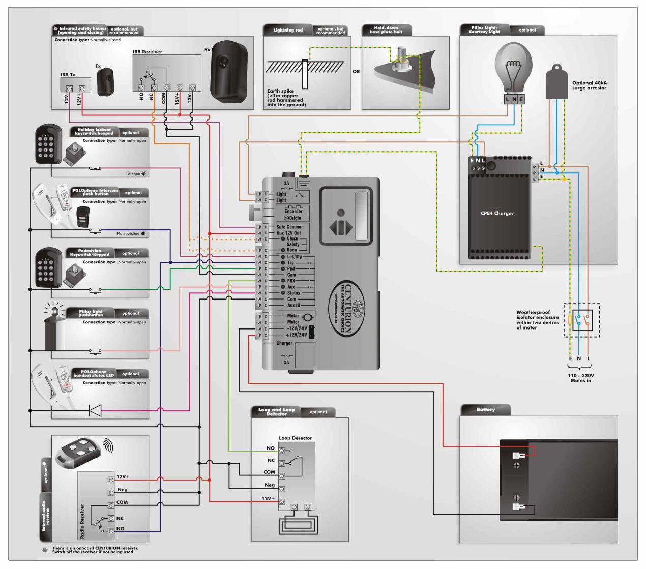
Prior to commissioning the system, please ensure that you have connected the wiring of all components in the system to the controller terminals correctly. Kindly refer to the diagrams provided on the back of this document for details.

The schedule of Factory Defaults are detailed in the full
installation manual, available for download on
www.centsys.co.za
Icon Sub-menuMenu
4. Modes of operation
4.1. Operating mode 4.1.1. Standard Mode
4.1.2. Condominium Mode
4.1.3. Reversing Mode
4.1.4. PLC
4.1.5. Deadman Control Mode
1.1. Setup wizard1. Setting limits
2. Safety
2.1. Collision force 2.1.1. Opening collision force
2.1.2. Closing collision force
2.5.1. Indicator output
2.5.2. Closed indication
2.5.3. Part close indication
2.5.4. Closing indication
2.5.5. Part open indication
2.5.6. Opening indication
2.6.7. Open indication
2.5.8. Pedestrian indication
2.5.9. Unknown indication
2.2. Collision count
2.3. Alarm output
2.4. LCK input as ESTOP
2.5. External gate indication status
3. Autoclose
3.1. Autoclose Status
3.2. Autoclose Timer
3.3. Autoclose Override
3.4. Autoclose advanced options 3.4.1. Autoclose fully open
3.4.2. Autoclose partly open
3.4.3. Autoclose partly closed
5. Run profile
5.1. Positive Close Mode 5.1.1. Positive Close Mode Status
5.1.2. Positive Close Mode Force
5.2. Pre-open delay
5.3. Pre-close delay
5.4 Opening speed
5.5. Closing speed
5.6. Ramp-up distance
5.7. Ramp-down distance
5.8. TRG stop distance
5.9. IRB stop distance
5.10.Crawl distance
5.11.Torque limit

Icon Sub-menuMenu
7. Pedestrian
7.1. Pedestrian open position
7.2. Pedestrian Autoclose time
7.3. Pedestrian pre-open delay
7.4. Pedestrian pre-close delay
6. Infrared beams
6.1. PIRAC control 6.1.1. PIRAC status
6.1.2. Stop on open
6.1.2.1. Stop on open status
6.1.2.2. Stopping distance
6.2.1. On/Off
6.2.2. Test beam selection (IRBC; IRBO; IRBC and IRBO)
6.4.1. Ambush Alarm
6.4.1.1. Ambush Alarm on/off
6.4.1.2. Broken IRB time
6.3. IRBO=IRBC on closing
6.4. IR beam alarms
6.2. IR beam test
6.4.2. Break-in Alarm on/off
6.4.3. Alarm output selection
8. Courtesy Light
8.1. Courtesy Light Timer
8.2. Light Profile 8.2.1. Courtesy Light
8.2.2. Pre-flash A
8.2.3. Pre-flash B
8.2.4. Pre-flash C
9.4. Delete all Time-periods
and exclusions
9. ChronoGuard
9.1. Time and date
9.2. Time-Periods 9.2.1. Add Time-period
9.2.1.1. Auto function
9.2.1.2. Time-bar function
9.3.1.1. Auto function
9.3.1.2. Time-bar function
9.3. Exclusions
9.2.2. Delete Time-period
9.2.3. Edit review Time-periods
9.3.1. Add exclusion
9.3.2. Delete exclusion
9.3.3. Edit review exclusions

Icon Sub-menuMenu
10. General settings
10.1.Operating standard (ZA; CE; UL325)
10.2.Reset options 10.2.1.Factory defaults
10.2.2.Delete all remotes
10.2.3.Delete all Time-periods and exclusions
10.2.4.Reset all
10.3.Diagnostic screen on/off
10.4.Test button disabled/enabled
10.5.Backup EEPROM
10.6.Restore EEPROM
11.1.Add remotes
11.2.Delete remotes 11.2.1. Delete remote by ID
11.2.2. Delete remote button
11.2.3. Delete remote by button
11.2.4. Delete not present On/Off
11.2.5. Delete all remotes
11. Remote controls
11.3.Edit remote button
11.4.Autolearn
11.5.Lock Tx menu
11.6.Onboard receiver enable/disable
Press button of valid transmitter (if menu locked)

Lck/Stp - green LED when the Lck/Stp
input is not activatedOn
Trg - red LED when the trigger signal
is presentOn
Ped - red LED when the pedestrian
signal is presentOn
FRX - red LED when a free-exit
signal is presentOn
Aux - red LED when an auxiliary
signal is presentOn
Status- red LEDThis LED indicated the status of the gate as per the table below:
LED indication Gate status
Off Gate is closed
On Gate is partially or fully open
Continuous slow flash Gate is opening
Continuous fast flash Gate is closing
One flash every two seconds Pillar Light Override is activated
Two flashes every two seconds No mains present
Safety Close - green LEDOn when the closing beam is not activated
Safety Open - green LED when the opening
beam is not activatedOn
4. Diagnostic LEDs
The D5-Evo and D10 controllers have a series of diagnostic LEDs which indicate the state of the inputs.
Normally-open inputs are indicated by a red LED, and normally-closed inputs by a green LED.
An illuminated red LED indicates that the signal is present (e.g. intercom button pressed), while a non-illuminated green LED indicates that the signal is absent (e.g. IRB broken).

LED indication
Three flashes every two seconds Battery voltage is low
Four flashes every two seconds Multiple collisions have occurred
LED indication Gate status
1. Battery iconIndicates the state of charge of the battery.
&Four solid bars = full capacity
&Two solid bars = 50% capacity
&No solid bars, with the icon flashing = battery empty
2. Mains iconDisplays the presence or absence of mains voltage:
Plug solid = mains present and battery charging
Plug hollow and flashing = No mains present and battery not charging
3. Autoclose information Displays the state of the Autoclose function
Displays off if Autoclose is not selected
OVR if Autoclose is overridden, and the remaining Autoclose time if Autoclose is active
POVR indicates that the PIRAC option is overriden
4. Pillar light information Displays the remaining light time if Courtesy Light Mode is selected
Pre-flashing mode is displayed if pre-flash is selected
LIT will be indicated if the pillar light has been turned on permanently
&
&
&
&
&
&
&
&
&
The LCD display shows useful information regarding the status of the system.

Inhibitor name Number of beepsPriority Fault typeGate
continuesto operate
User can correct error
Break-in alarm Continuous tone for 30 seconds Alarm N/A N/A
Ambush alarm Continuous tone until IRBs are cleared Alarm N/A N/A
Multiple collision Periodic until condition is cleared by user (500/500ms) Collision No Yes
Battery low Three beeps periodically for 30 seconds Power system fault Yes* Yes
Auxiliary overload Five beeps periodically for 30 seconds Hardware No No
Holiday Lockout One beep periodically for 30 seconds User No Yes
Emergency stop One beep periodically for 30 seconds User No Yes
Time-barring One beep periodically for 5 seconds User No Yes
No limits set Three short beeps for 5 seconds Lost No Yes
Mains failure Two beeps periodically for 30 seconds Power system fault Yes Yes
Beams broken (any) One beep periodically for 30 seconds User No Yes
Beams failure Five beeps periodically for 30 seconds Hardware No No
DOSS disconnected Five beeps periodically for 30 seconds Hardware No No
Fuse blown Five beeps periodically for 30 seconds Hardware No Yes
Motor disconnected Five beeps periodically for 30 seconds Hardware No Yes
Bridge damaged Five beeps periodically for 30 seconds Hardware No No
Gate stalled Four beeps periodically for 10 seconds Collision No Yes
No magnet detected Periodic while gate runs(500/500ms) Lost Yes Yes
A warning buzzer will sound (where applicable) as per the table below:
Gate will close fully and then shutdown for two minutes

1. Always check that the circuit breaker in the electrical panel is in the OFF position, and that all high voltage circuits (more than 42.4V) are completely isolated from the mains supply before doing any work.
2. Ensure that all low voltage systems (less than 42.4V) are suitably protected from damage, by disconnecting all sources of power such as chargers and batteries before doing any work.
3. All electrical work must be carried out according to the requirements of all applicable local electrical codes. (It is recommended that a licensed electrical contractor perform such work).
Connect all wiringConnect the controller to the required input and output devices as per the wiring diagram on the right hand side.
Safety Open Opening beam safety input. (A normally-closed potential-free input)
Light/Light Pillar light connection. (A normally-open potential-free input)
Safe Common Used for switching the power supply to the safety beams, if automatic beam testing is required
Aux 12V Out Auxiliary power connection. Provides +12V DC supply for auxiliary equipment such as a radio receiver, photo cells, etc. It is electronically limited to 300mA
Safety Close Closing beam safety input. (A normally-closed potential-free input)
Lck/Stp Holiday Lockout or emergency stop input. (A normally-closed potential-free input)
Trg Trigger input. (A normally-open potential-free input)
FRX Free-exit input. (A normally-open potential-free input)
Aux Activates the pillar light relay. (A normally-open potential-free input).
Ped Pedestrian opening input. (A normally-open potential-free input)
Com Common termination point. All trigger signals, etc. have their return path to one of the Com terminals
Status External gate status indicator. (A low current output signal). An output terminal which provides a low current, drive (approx. 4,5V DC, 20mA) to a LED which can be used to indicate the gate status remotely)
Aux IO The Aux IO terminal provides an open collector output which can be used for alarm or auto function purposes

Motor Motor output – connects to the thick blue motor wire
Motor Motor output – connects to the thick black motor wire
12V/24 + Positive battery connection.
12V/24 - Negative battery connection.
Battery terminal normally indicated as + or red (right hand battery)
Battery terminal normally indicated as - or black (left hand battery)
12V/24V this will either be 12V or 24V depending on the motor voltage of the operator
Once the installation has been successfully completed and tested, it is important for the installer to explain the operation and safety requirements of the system.
A switch that remains in a connected or disconnected state similar to a standard light switch
A switch that momentarily makes contact, and may be spring loaded similar to a push button door step
Latched
Non-Latched


![Copyright © C. J. Date 2005page 97 S#Y S1DURINGS3DURING [d04:d10][d08:d10] S2DURINGS4DURING [d02:d04][d04:d10] [d08:d10] WITH ( EXTEND T2 ADD ( COLLAPSE](https://img.dokumen.tips/doc/110x75/56649c765503460f9492abbb/copyright-c-j-date-2005page-97-sy-s1durings3during-d04d10d08d10.jpg)