Embed Size (px)
Citation preview

100sx
Operator’s Manual
Issue 1.0Original Instruction
053-2815

100sx Operator’s Manual Overview - 1
Overview
Chapter Contents
Serial Number Location . . . . . . . . . . . . . . . . . . . . . . 2
Intended Use . . . . . . . . . . . . . . . . . . . . . . . . . . . . . . . 3
Unit Components . . . . . . . . . . . . . . . . . . . . . . . . . . . 4
Operator Orientation. . . . . . . . . . . . . . . . . . . . . . . . . 5
About This Manual . . . . . . . . . . . . . . . . . . . . . . . . . . 5
• Bulleted Lists. . . . . . . . . . . . . . . . . . . . . . . . . . . . . . . . . . . . . . . . . . . . . . 5
• Numbered Lists . . . . . . . . . . . . . . . . . . . . . . . . . . . . . . . . . . . . . . . . . . . . 5

Overview - 2 100sx Operator’s ManualSerial Number Location
Serial Number LocationRecord serial numbers and date of purchase in the spaces provided.
Date of manufacture
Date of purchase
100sx plow serial number (2)
Engine serial number (1)
t44om002w.eps
1
2
100sx Operator’s Manual Overview - 3Intended Use
Intended UseThe 100SX is a self-propelled, walk-along vibratory plow. The 100SX is powered by a 13 hp (9.7 kW) Briggs & Stratton® engine and is designed to operate in a variety of soil conditions with either a pull or feed blade.
The unit is designed for operation in temperatures typically experienced in excavation and construction work environments. Provisions may be required to operate in extreme temperatures. Contact your Ditch Witch® dealer. Use in any other way is considered contrary to the intended use.
The 100sx should be operated, serviced, and repaired only by persons familiar with its particular characteristics and acquainted with the relevant safety procedures.

Overview - 4 100sx Operator’s ManualUnit Components
Unit Components
1. Control panel/operator position
2. Engine
3. Weight assembly
4. Blade mount bracket
t44om004w.eps
1 2
3
4
100sx Operator’s Manual Overview - 5Operator Orientation
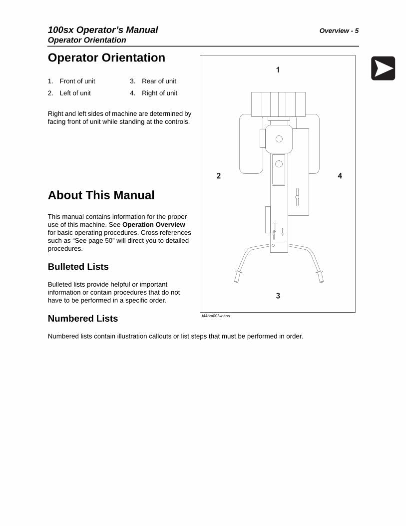
Operator Orientation
Right and left sides of machine are determined by facing front of unit while standing at the controls.
About This ManualThis manual contains information for the proper use of this machine. See Operation Overview for basic operating procedures. Cross references such as “See page 50” will direct you to detailed procedures.
Bulleted Lists
Bulleted lists provide helpful or important information or contain procedures that do not have to be performed in a specific order.
Numbered Lists
Numbered lists contain illustration callouts or list steps that must be performed in order.
1. Front of unit
2. Left of unit
3. Rear of unit
4. Right of unit
11
33
4422
t44om003w.eps

Overview - 6 100sx Operator’s ManualAbout This Manual

100sx Operator’s Manual Foreword - 7
Foreword
This manual is an important part of your equipment. It provides safety information and operation instructions to help you use and maintain your Ditch Witch® equipment.
Read this manual before using your equipment. Keep it with the equipment at all times for future reference. If you sell your equipment, be sure to give this manual to the new owner.
If you need a replacement copy, contact your Ditch Witch dealer. If you need assistance in locating a dealer, visit our website at www.ditchwitch.com or write to the following address:
The Charles Machine Works, Inc.Attn: Marketing DepartmentPO Box 66Perry, OK 73077-0066 USA
The descriptions and specifications in this manual are subject to change without notice. The Charles Machine Works, Inc. reserves the right to improve equipment. Some product improvements may have taken place after this manual was published. For the latest information on Ditch Witch equipment, see your Ditch Witch dealer.
Thank you for buying and using Ditch Witch equipment.

Foreword - 8 100sx Operator’s Manual
100sxOperator’s Manual
Issue number 1.0/OM-03/15Part number 053-2815
Copyright 2015by The Charles Machine Works, Inc.
, Ditch Witch, CMW, and Roto Witch are registered trademarks of The Charles Machine Works, Inc.

100sx Operator’s Manual Contents - 9
Contents
Overviewmachine serial number, information about the type of work this machine is designed to perform, basic machine components, and how to use this manual
1
Forewordpart number, revision level, and publication date of this manual, and factory contact information
7
Safetymachine safety alerts and emergency procedures
11
Controlsmachine controls, gauges, and indicators and how to use them
21
Operation Overviewan overview for completing a job with this machine: planning, setting up, installing product, and restoring the jobsite; with cross references to detailed procedures
25
Prepareprocedures for inspecting and classifying the jobsite, planning the installation path, and preparing the jobsite for work
27
Driveprocedures for startup, cold start, driving, and shutdown
33
Transportprocedures for lifting, hauling, and towing
37
Plowprocedures for plowing
43
Systems and EquipmentROPS, plow blades, and optional equipment
49
Complete the Jobprocedures for backfilling and restoring the jobsite and rinsing and storing equipment
53
Serviceservice intervals and instructions for this machine including lubrication, replacement of wear items, and basic maintenance
55

Contents - 10 100sx Operator’s Manual
Specificationsmachine specifications including weights, measurements, power ratings, and fluid capacities
71
Supportthe warranty policy for this machine, and procedures for obtaining warranty consideration and training
75
Service Recorda record of major service performed on the machine
79
100sx Operator’s Manual Safety - 11
Safety
Chapter Contents
Guidelines . . . . . . . . . . . . . . . . . . . . . . . . . . . . . . . . 12
Emergency Procedures . . . . . . . . . . . . . . . . . . . . . 13
• Electric Strike Description . . . . . . . . . . . . . . . . . . . . . . . . . . . . . . . . . . . 13
• If an Electric Line is Damaged . . . . . . . . . . . . . . . . . . . . . . . . . . . . . . . 14
• If a Gas Line is Damaged . . . . . . . . . . . . . . . . . . . . . . . . . . . . . . . . . . . 14
• If a Fiber Optic Cable is Damaged . . . . . . . . . . . . . . . . . . . . . . . . . . . . 15
• If Machine Catches on Fire . . . . . . . . . . . . . . . . . . . . . . . . . . . . . . . . . . 15
Safety Alert Classifications . . . . . . . . . . . . . . . . . . 17
Machine Safety Alerts . . . . . . . . . . . . . . . . . . . . . . 18

Safety - 12 100sx Operator’s ManualGuidelines
GuidelinesFollow these guidelines before operating any jobsite equipment:
• Complete proper training and read operator’s manual before using equipment.
• Contact your local One-Call (811 in USA) or the One-Call referral number (888-258-0808 in USA and Canada) to have underground utilities located before digging. Also contact any utilities that do not participate in the One-Call service. Mark proposed path with white paint prior to contacting One-Call or utilities.
• Classify jobsite based on its hazards and use correct tools and machinery, safety equipment, and work methods for jobsite.
• Mark jobsite clearly and keep spectators away.
• Wear personal protective equipment.
• Review jobsite hazards, safety and emergency procedures, and individual responsibilities with all personnel before work begins. Safety videos are available from your Ditch Witch® dealer or at ditchwitch.com/resources/safety.
• Replace missing or damaged safety shields and safety signs.
• Use equipment carefully. Stop operation and investigate anything that does not look or feel right.
• Do not operate unit where flammable gas may be present.
• Contact your Ditch Witch dealer if you have any question about operation, maintenance, or equipment use.
• Complete the equipment checklist located at www.ditchwitch.com/resources/safety.

100sx Operator’s Manual Safety - 13Emergency Procedures
Emergency Procedures
Before operating any equipment, review emergency procedures and check that all safety precautions have been taken.
Electric Strike Description
When working near electric cables, remember the following:
• Electricity follows all paths to ground, not just path of least resistance.
• Pipes, hoses, and cables will conduct electricity back to all equipment.
• Low voltage current can injure or kill. Many work-related electrocutions result from contact with less than 440 volts.
Most electric strikes are not noticeable, but indications of a strike include:
• power outage
• smoke
• explosion
• popping noises
• arcing electricity
If any of these occur, assume an electric strike has occurred.
Jobsite hazards could cause death or serious injury. Use correct equipment and work methods. Use and maintain proper safety equipment. 274-050
EMERGENCY SHUTDOWN - Release all controls and turn ignition switch to STOP.
Electric shock. Contacting electric lines will cause death or serious injury. Know location of lines and stay away.
Safety - 14 100sx Operator’s ManualEmergency Procedures
If an Electric Line is Damaged
If you suspect an electric line has been damaged and you are near pedestrian unit, DO NOT MOVE and do not touch unit. Take the following actions. The order and degree of action will depend upon the situation.
• Warn people nearby that an electric strike has occurred. Instruct them to leave the area and contact utility.
• Do not allow anyone into area until given permission by utility company.
• Do not allow anyone to touch equipment.
If a Gas Line is Damaged
If you suspect a gas line has been damaged, take the following actions. The order and degree of action will depend on the situation.
• Immediately shut off engine(s), if this can be done safely and quickly.
• Remove any ignition source(s), if this can be done safely and quickly.
• Warn others that a gas line has been cut and that they should leave the area.
• Leave jobsite as quickly as possible.
• Immediately call your local emergency phone number and utility company.
• If jobsite is along street, stop traffic from driving near jobsite.
• Do not return to jobsite until given permission by emergency personnel and utility company.
100sx Operator’s Manual Safety - 15Emergency Procedures
If a Fiber Optic Cable is Damaged
Do not look into cut ends of fiber optic or unidentified cable. Vision damage can occur. Contact utility company.
If Machine Catches on Fire
Perform emergency shutdown procedure and then take the following actions. The order and degree of action will depend on the situation.
• Immediately move battery disconnect switch (if equipped and accessible) to disconnect position.
• If fire is small and fire extinguisher is available, attempt to extinguish fire.
• If fire cannot be extinguished, leave area as quickly as possible and contact emergency personnel.

Safety - 16 100sx Operator’s ManualEmergency Procedures

100sx Operator’s Manual Safety - 17Safety Alert Classifications
Safety Alert ClassificationsThese classifications and the icons defined on the following pages work together to alert you to situations which could be harmful to you, jobsite bystanders or your equipment. When you see these words and icons in the book or on the machine, carefully read and follow all instructions. YOUR SAFETY IS AT STAKE.
Watch for the three safety alert levels: DANGER, WARNING and CAUTION. Learn what each level means.
indicates a hazardous situation that, if not avoided, will result in death or serious injury. This signal word is to be limited to the most extreme situations.
indicates a hazardous situation that, if not avoided, could result in death or serious injury.
indicates a hazardous situation that, if not avoided, could result in minor or moderate injury.
Watch for two other words: NOTICE and IMPORTANT.
NOTICE indicates information considered important, but not hazard-related (e.g., messages relating to property damage).
IMPORTANT can help you do a better job or make your job easier in some way.

Safety - 18 100sx Operator’s ManualMachine Safety Alerts
Machine Safety Alerts
1
Jobsite hazards could cause death or serious injury. Use correct equipment and work methods. Use and maintain proper safety equipment. 274-050; 274-724 (2P)
2
Tiedown location. See Transport chapter for more information.274-318
3
Hot parts may cause burns. Do not touch until cool or wear gloves. 275-355 (2-P), 273-423 (2-P)
4
Fire or explosion possible. Fumes could ignite and cause burns. No smoking, no flame, no spark. 275-419 (2P)
t44om001w.eps
22
2233
44
22
66
55
11
100sx Operator’s Manual Safety - 19Machine Safety Alerts
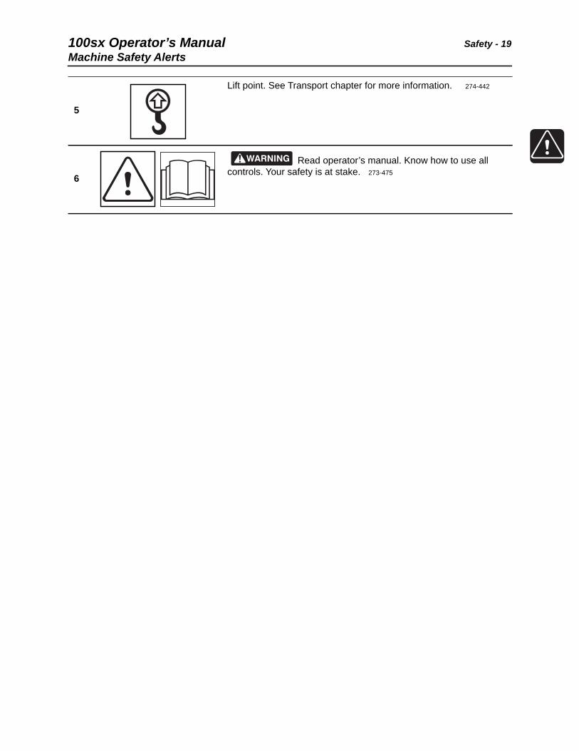
5
Lift point. See Transport chapter for more information. 274-442
6
Read operator’s manual. Know how to use all controls. Your safety is at stake. 273-475

Safety - 20 100sx Operator’s ManualMachine Safety Alerts

100sx Operator’s Manual Controls - 21
Controls
Chapter Contents
Plow . . . . . . . . . . . . . . . . . . . . . . . . . . . . . . . . . . . . . 22

Controls - 22 100sx Operator’s ManualPlow
Plow
1. Choke
2. Fuel shutoff valve
3. Plow control
4. Speed/direction control
5. Throttle lever
6. Ignition switch
7. Operator presence switch
Item Description Notes
1. Choke Push lever forward before starting.
Pull lever back after engine is running.
t44om005w.eps
1 2 3 4 5 6 7

100sx Operator’s Manual Controls - 23Plow
2. Fuel shutoff valve Open to allow fuel flow to engine.
Close to shut off fuel flow to engine.
3. Plow control Push lever forward to engage plow vibrator.
Pull lever backward to disengage plow vibrator.
4. Speed/direction control To move machine forward, move lever to forward position.
To move machine backward, move lever to reverse position.
To increase speed in either direction, move control farther from neutral.
To stop movement, move control to neutral position.
Control automatically returns to neutral position if released in reverse position.
5. Throttle lever Move lever forward to increase vibrator speed when plow is engaged.
Move lever backward to decrease vibrator speed when plow is engaged.
Item Description Notes
c00ic622w.eps
c00ic124w.eps
c00ic125w.eps
c00ic243h.eps

Controls - 24 100sx Operator’s ManualPlow
6. Ignition switch Insert key and turn to ON position to enable rope start.
Turn key to OFF position to stop engine.
IMPORTANT: Before starting machine:
• ensure plow control is disengaged
• move speed/direction control to neutral position
7. Operator presence switch
Detects when operator is present.
Press and hold at least one switch before moving ground drive control or digging control out of neutral.
NOTICE: Do not wire or tape operator presence switch to handlebar or defeat interlock system in any manner. Ground drive and digging controls will not function.
Item Description Notes
c00ic126w.eps
100sx Operator’s Manual Operation Overview - 25
Operation Overview
Chapter Contents
Planning. . . . . . . . . . . . . . . . . . . . . . . . . . . . . . . . . . 26
Plowing . . . . . . . . . . . . . . . . . . . . . . . . . . . . . . . . . . 26
Leaving Jobsite. . . . . . . . . . . . . . . . . . . . . . . . . . . . 26

Operation Overview - 26 100sx Operator’s ManualPlanning
Planning1. Gather information about jobsite. See page 28.
2. Inspect jobsite. See page 29.
3. Classify jobsite. See page 30.
4. Select plow blade for your installation. See page 51
5. Check supplies and prepare equipment. See page 32.
6. Haul equipment to jobsite. See page 39.
Plowing1. Start unit. See page 34.
2. Position plow and controls. See page 45.
3. Attach product. See page 45.
4. Begin plowing. See page 46.
5. Complete the installation. See page 53.
6. Shut down plow. See page 35.
Leaving Jobsite1. Rinse equipment. See page 54.
2. Stow tools. See page 54.
3. Haul equipment away from jobsite. See page 39.

100sx Operator’s Manual Prepare - 27
Prepare
Chapter Contents
Gather Information . . . . . . . . . . . . . . . . . . . . . . . . . 28
• Review Job Plan . . . . . . . . . . . . . . . . . . . . . . . . . . . . . . . . . . . . . . . . . . 28
• Notify One-Call Services . . . . . . . . . . . . . . . . . . . . . . . . . . . . . . . . . . . . 28
• Arrange for Traffic Control . . . . . . . . . . . . . . . . . . . . . . . . . . . . . . . . . . . 28
• Plan for Emergency Services . . . . . . . . . . . . . . . . . . . . . . . . . . . . . . . . 28
Inspect Site . . . . . . . . . . . . . . . . . . . . . . . . . . . . . . . 29
• Identify Hazards . . . . . . . . . . . . . . . . . . . . . . . . . . . . . . . . . . . . . . . . . . 29
Classify Jobsite. . . . . . . . . . . . . . . . . . . . . . . . . . . . 30
• Inspect Jobsite . . . . . . . . . . . . . . . . . . . . . . . . . . . . . . . . . . . . . . . . . . . 30
• Select a Classification . . . . . . . . . . . . . . . . . . . . . . . . . . . . . . . . . . . . . . 30
• Apply Precautions . . . . . . . . . . . . . . . . . . . . . . . . . . . . . . . . . . . . . . . . . 31
Check Supplies and Prepare Equipment . . . . . . . 32
• Supplies . . . . . . . . . . . . . . . . . . . . . . . . . . . . . . . . . . . . . . . . . . . . . . . . 32
• Fluid Levels . . . . . . . . . . . . . . . . . . . . . . . . . . . . . . . . . . . . . . . . . . . . . . 32
• Condition and Function . . . . . . . . . . . . . . . . . . . . . . . . . . . . . . . . . . . . . 32
• Accessories . . . . . . . . . . . . . . . . . . . . . . . . . . . . . . . . . . . . . . . . . . . . . . 32

Prepare - 28 100sx Operator’s ManualGather Information
Gather InformationA successful job begins before you dig. The first step in planning is reviewing information already available about the job and jobsite.
Review Job Plan
Review blueprints or other plans. Check for information about existing or planned structures, elevations, or proposed work that may be taking place at the same time.
Notify One-Call Services
Contact your local One-Call (811 in USA) or the One-Call referral number (888-258-0808 in USA and Canada) to have underground utilities located before digging. Also contact any utilities that do not participate in the One-Call service.
Arrange for Traffic Control
If working near a road or other traffic area, contact local authorities about safety procedures and regulations.
Plan for Emergency Services
Have the telephone numbers for local emergency and medical facilities on hand. Check that you will have access to a telephone.

100sx Operator’s Manual Prepare - 29Inspect Site
Inspect SiteInspect jobsite before transporting equipment. Check for the following:
• changes in elevation such as hills or other open trenches
• obstacles such as buildings, railroad crossings, or streams
• signs of utilities (See “Inspect Jobsite” on page 30.)
• traffic
• access
• soil type and condition
Identify Hazards
Identify safety hazards and classify jobsite. See “Classify Jobsite” on page 30.
Jobsite hazards could cause death or serious injury. Use correct equipment and work methods. Use and maintain proper safety equipment.
To help avoid injury:
• Wear personal protective equipment including hard hat, safety eye wear, and hearing protection.
• Do not wear jewelry or loose clothing.
• Notify One-Call and companies which do not subscribe to One-Call.
• Comply with all utility notification regulations before digging or drilling.
• Verify location of previously marked underground hazards.
• Mark jobsite clearly and keep spectators away.
Remember, jobsite is classified by hazards in place -- not by line being installed.

Prepare - 30 100sx Operator’s ManualClassify Jobsite
Classify Jobsite
Inspect Jobsite
• Follow U.S. Department of Labor regulations on excavating and trenching (Part 1926, Subpart P) and other similar regulations.
• Contact your local One-Call (811 in USA) or the One-Call referral number (888-258-0808 in USA and Canada) to have underground utilities located before digging. Also contact any utilities that do not participate in the One-Call service.
• Inspect jobsite and perimeter for evidence of underground hazards, such as:
– “buried utility” notices
– utility facilities without overhead lines
– gas or water meters
– junction boxes
– drop boxes
– light poles
– manhole covers
– sunken ground
• Have an experienced locating equipment operator sweep area within 20’ (6 m) to each side of trench path. Verify previously marked line and cable locations.
• Mark location of all buried utilities and obstructions.
• Classify jobsite.
Select a Classification
Jobsites are classified according to underground hazards present.
If working... then classify jobsite as...
within 10’ (3 m) of a buried electric line electric
within 10’ (3 m) of a natural gas line natural gas
in sand, granite, or concrete which is capable of producing crystalline silica (quartz) dust
crystalline silica (quartz) dust
within 10’ (3 m) of any other hazard other
NOTICE: If you have any doubt about jobsite classification, or if jobsite might contain unmarked hazards, take steps outlined previously to identify hazards and classify jobsite before working.
100sx Operator’s Manual Prepare - 31Classify Jobsite
Apply Precautions
Once classified, precautions appropriate for jobsite must be taken.
Electric Jobsite Precautions
Use one or both of these methods.
• Expose line by careful hand digging or soft excavation.
• Have service shut down while work is in progress. Have electric company test lines before returning them to service.
Natural Gas Jobsite Precautions
In addition to positioning equipment upwind from gas lines, use one or both of these methods.
• Expose lines by careful hand digging or soft excavation.
• Have gas shut off while work is in progress. Have gas company test lines before returning them to service.
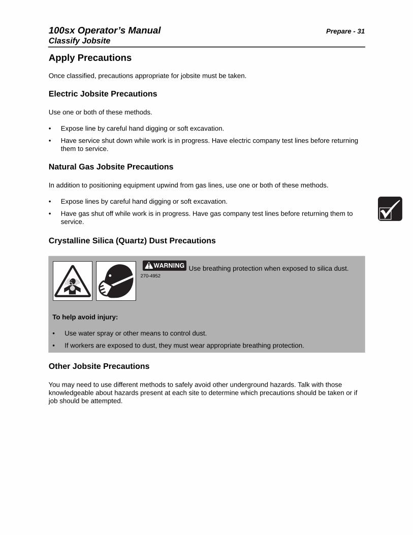
Crystalline Silica (Quartz) Dust Precautions
Other Jobsite Precautions
You may need to use different methods to safely avoid other underground hazards. Talk with those knowledgeable about hazards present at each site to determine which precautions should be taken or if job should be attempted.
Use breathing protection when exposed to silica dust. 270-4952
To help avoid injury:
• Use water spray or other means to control dust.
• If workers are exposed to dust, they must wear appropriate breathing protection.

Prepare - 32 100sx Operator’s ManualCheck Supplies and Prepare Equipment
Check Supplies and Prepare Equipment
Supplies
• fuel
• keys
• personal protective equipment, such as hard hat and safety glasses
Fluid Levels
• fuel
• hydraulic fluid
• battery charge
• engine oil
Condition and Function
• digging chain and teeth
• fan belts
• light bulbs
• filters (air, oil, hydraulic)
• tires
• pumps and motors
• hoses and valves
• signs, guards, and shields
Accessories
Fire Extinguisher
If required, mount a fire extinguisher near the power unit but away from possible points of ignition. The fire extinguisher should always be classified for both oil and electric fires. It should meet legal and regulatory requirements.
100sx Operator’s Manual Drive - 33
Drive
Chapter Contents
Start Unit . . . . . . . . . . . . . . . . . . . . . . . . . . . . . . . . . 34
Drive . . . . . . . . . . . . . . . . . . . . . . . . . . . . . . . . . . . . . 35
Shut Down . . . . . . . . . . . . . . . . . . . . . . . . . . . . . . . . 35

Drive - 34 100sx Operator’s ManualStart Unit
Start UnitBefore operating plow, read engine manufacturer’s starting and operating instructions. Follow instructions for new engine break-in.
1. Move all controls and switches to the neutral or disengaged position.
2. Open fuel shutoff valve.
3. Insert key into ignition switch and turn to the ON position.
4. Set throttle at low idle.
5. Choke to start cold engine.
6. Pull briskly on starter-rope handle at left side of machine.
• If engine does not start after three pulls on rope start, turn key switch to OFF position and check for fuel blockage or ignition system problems.
7. Run engine at half-throttle or less for five minutes before operating plow. During warm-up, check that all controls work properly.
8. Return choke to open position if needed.
Runaway possible. Machine could run over you or others. Learn how to use all controls. Start and operate only from operator’s position.
Read operator’s manual. Know how to use all controls. Your safety is at stake. 273-475
To help avoid injury:
• Read operator’s manual before operating equipment. Follow instructions carefully. Contact your Ditch Witch® dealer for operation information or demonstration.
• Wear hard hat, safety glasses, and other protective equipment required by job. Do not wear jewelry or loose clothing that can catch on controls.

100sx Operator’s Manual Drive - 35Shut Down
Drive
1. Remove or reposition plow blade for ground clearance.
2. Check that tires are positioned straight or in direction of intended movement.
3. Press and hold operator presence switch.
4. Move ground drive control in desired direction of travel.
5. Adjust throttle for desired speed of travel.
Shut Down1. When job is complete, move ground drive control to neutral.
2. Return all controls to neutral or disengaged position.
3. Move throttle to low idle for 2-3 minutes to cool.
4. Turn ignition switch to OFF position. If leaving machine unattended, remove key.
5. Close fuel shutoff valve.
EMERGENCY SHUTDOWN: Turn ignition switch to STOP.
NOTICE: Machine should not be parked on a slope unless chocked, blocked, or parking brake engaged.

Drive - 36 100sx Operator’s ManualShut Down

100sx Operator’s Manual Transport - 37
Transport
Chapter Contents
Lift . . . . . . . . . . . . . . . . . . . . . . . . . . . . . . . . . . . . . . 38
• Points . . . . . . . . . . . . . . . . . . . . . . . . . . . . . . . . . . . . . . . . . . . . . . . . . . 38
• Procedure . . . . . . . . . . . . . . . . . . . . . . . . . . . . . . . . . . . . . . . . . . . . . . . 38
Haul . . . . . . . . . . . . . . . . . . . . . . . . . . . . . . . . . . . . . 39
Tie Down . . . . . . . . . . . . . . . . . . . . . . . . . . . . . . . . . 40
• Points . . . . . . . . . . . . . . . . . . . . . . . . . . . . . . . . . . . . . . . . . . . . . . . . . . 40
• Procedure . . . . . . . . . . . . . . . . . . . . . . . . . . . . . . . . . . . . . . . . . . . . . . . 40
Transport - 38 100sx Operator’s ManualLift
Lift
Points
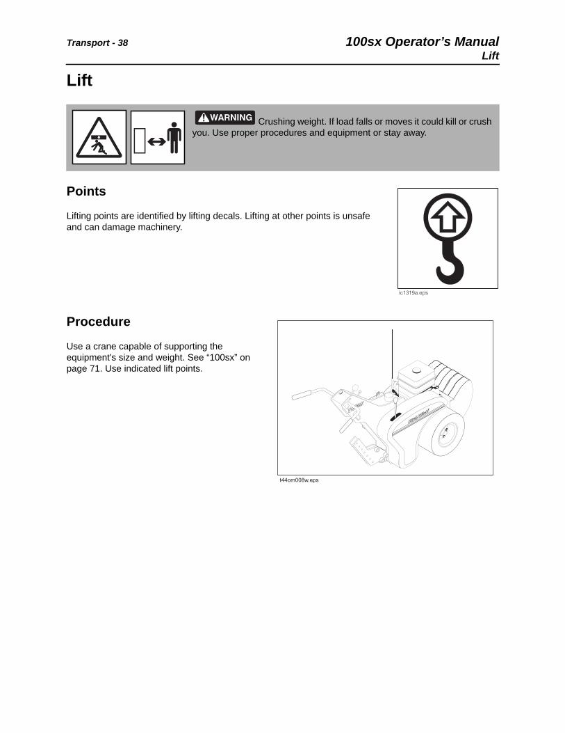
Lifting points are identified by lifting decals. Lifting at other points is unsafe and can damage machinery.
Procedure
Use a crane capable of supporting the equipment's size and weight. See “100sx” on page 71. Use indicated lift points.
Crushing weight. If load falls or moves it could kill or crush you. Use proper procedures and equipment or stay away.
t44om008w.eps
100sx Operator’s Manual Transport - 39Haul
Haul
Load
1. Start engine. See page 34 for proper start-up procedures.
2. Reposition or remove plow blade.
3. Slowly drive plow onto trailer.
4. Position plow on trailer deck for proper weight distribution.
5. Turn plow off. See page 35 for proper shutdown procedures.
6. Attach chains to plow where tie-down decals are located. See page 40.
Crushing weight. If load falls or moves it could kill or crush you. Use proper procedures and equipment or stay away.
To help avoid injury:
• Load unit with engine in low idle.
• Load trailer on level ground.
• Load trailer correctly to avoid trailer swaying.
• Attach trailer to vehicle before loading or unloading.
• If loading onto a tilt-bed trailer, ensure that tilt latch is secured in the correct position.
• Ten to fifteen percent of total vehicle weight (equipment plus trailer) must be on tongue to help prevent trailer sway.

Transport - 40 100sx Operator’s ManualTie Down
Tie Down
Points
Tie-down points are identified by tie-down decals. Securing to trailer at other points is unsafe and can damage machinery.
Procedure
Attach chains at front and rear tie-down points. Make sure chains are tight before transporting unit.
t44om007w.eps

100sx Operator’s Manual Transport - 41Tie Down
Unload
1. Lower trailer or ramps.
2. Remove chains from tiedowns.
3. Start plow. See page 34 for proper start-up procedures.
4. Slowly back unit down trailer or ramps.
Crushing weight. If load falls or moves it could kill or crush you. Use proper procedures and equipment or stay away.
To help avoid injury:
• Unload unit with engine in low idle.
• Unload trailer on level ground.
• Attach trailer to vehicle before loading or unloading.
• If trailer tilts, ensure that tilt latch is secured in the correct position.

Transport - 42 100sx Operator’s ManualTie Down

100sx Operator’s Manual Plow - 43
Plow
Chapter Contents
Setup . . . . . . . . . . . . . . . . . . . . . . . . . . . . . . . . . . . . 44
• Position Plow. . . . . . . . . . . . . . . . . . . . . . . . . . . . . . . . . . . . . . . . . . . . . 45
• Attach Product. . . . . . . . . . . . . . . . . . . . . . . . . . . . . . . . . . . . . . . . . . . . 45
Operation . . . . . . . . . . . . . . . . . . . . . . . . . . . . . . . . . 46

Plow - 44 100sx Operator’s ManualSetup
Setup
EMERGENCY SHUTDOWN - Turn ignition switch to STOP.
Crushing weight could cause death or serious injury. Use proper procedures and equipment or stay away.
To help avoid injury: Keep everyone at least 6’ (2 m) from machine, attachments, and their range of movement.
Jobsite hazards could cause death or serious injury. Use correct equipment and work methods. Use and maintain proper safety equipment.
To help avoid injury: Comply with all utility notification regulations before digging or drilling.
Read operator’s manual. Know how to use all controls. Your safety is at stake. 273-475
NOTICE:
• Choose the correct plow blade length for the desired depth of material cover. If using a vertically adjustable, multi-depth blade, select the proper installation height.
• Do not operate vibrator unless plow blade is in the ground.

100sx Operator’s Manual Plow - 45Setup
Position Plow
1. Start plow. See page 34 for start-up procedures.
2. Drive to starting point. Move in line with planned path. See page 35 for operating procedures.
3. Lower plow blade to starting point of path.
4. Turn ignition switch to OFF.
Attach Product
To Pull Product
1. Insert material into pulling grip.
2. Tape grip with duct tape.
To Feed Product
1. Remove cable guide.
2. Feed cable through tube from top to bottom.
3. Replace cable guide and tighten fasteners.
4. Secure cable.
NOTICE: Keep everyone away from material being installed.
Plow_Pull_nobox.eps
Plow_Feed_nobox.eps
Plow - 46 100sx Operator’s ManualOperation
Operation
Crushing weight could cause death or serious injury. Use proper procedures and equipment or stay away.
Electrical shock. Contacting electrical lines will cause death or serious injury. Know location of lines and stay away.
To help avoid injury: Expose lines by hand before digging. Cutting high voltage cable can cause electrocution
Read operator’s manual. Know how to use all controls. Your safety is at stake. 273-475
NOTICE:
• Do NOT plow with the blade partially raised. Only operate the plow with blade fully in the ground.
• Do NOT move ground drive control to reverse with the blade in the ground.

100sx Operator’s Manual Plow - 47Operation
Start Plowing
1. Start unit. (See “Start Unit” on page 34.)
2. Adjust throttle to low idle.
3. Check that ground drive control is in neutral.
4. Move ground drive control forward to a slow speed and lower plow blade until it begins to break the soil.
5. Move the plow vibrator control to the ON position. PLOW WILL VIBRATE.
6. Lower the plow blade into the ground to full depth.
7. Increase engine speed to a point with the least plow vibration and the highest ground drive speed possible without tire slippage.
8. Check cable for damage during plowing. Run continuity checks on electric cable and check pipe pressure. Damage can result from improper operation, incorrect blade choice, striking underground obstructions, or other conditions.
NOTICE:
• Move slowly while lowering the plow blade into the ground.
• Do NOT move ground drive control to reverse with the blade in the ground.
• Do NOT plow with the blade partially raised.
t44om006w.eps

Plow - 48 100sx Operator’s ManualOperation
Finish Plowing
1. When installation is complete, move ground drive control to the neutral position.
2. With vibrator running, lower throttle speed and raise plow to just below ground level.
3. Move plow vibrator control to OFF.
4. Raise plow out of ground.
5. Turn ignition switch to OFF and remove product from plow.
6. Start plow and drive a short distance away from work site.
7. Shut down plow. See page 35 for proper shutdown procedures.
NOTICE: Do not operate vibrator when plow is out of the ground. This will cause excessive vibration and will cause rapid wear, and possible damage to the unit and product being installed.

100sx Operator’s Manual Systems and Equipment - 49
Systems and Equipment
Optional Equipment . . . . . . . . . . . . . . . . . . . . . . . . 50
Plow Blades. . . . . . . . . . . . . . . . . . . . . . . . . . . . . . . 51
• Blade Maintenance . . . . . . . . . . . . . . . . . . . . . . . . . . . . . . . . . . . . . . . . 51
• Blade Types . . . . . . . . . . . . . . . . . . . . . . . . . . . . . . . . . . . . . . . . . . . . . 51

Systems and Equipment - 50 100sx Operator’s ManualOptional Equipment
Optional Equipment
See your Ditch Witch® dealer for more information about the following optional equipment.
100sx Plow
Equipment Description
plow blades and pulling grips
Choose the most efficient plow blade for your job based on your desired cover depth range, feed chute diameter, and feed chute radius, as well as your desired speed for straight plowing.
tires 16” or 18” tires are available
counterweights required to balance unit configured with optional attachments
front reel carrier mounted on the front of the plow

100sx Operator’s Manual Systems and Equipment - 51Plow Blades
Plow Blades
Blade Maintenance
• Keep cable guide wing bolts tight. Loose cable guide bolts will break due to plow vibration.
• Keep plow feed tube free of rock and debris so that material pulls freely though tube.
• Use a speed blade only for straight or gently curving installations. Do not use speed blades for installations that require sharp turns.
• Use the plow blade most appropriate for the type of material being installed. Contact your Ditch Witch® dealer for information about the most effective blade for your jobsite conditions.
Blade Types
Type Description
feed blade used to “stitch” flexible material into the ground as it is fed through a chute or tube located at the back of the blade
speed blade a thin feed-type blade used for high speed, straight plowing
pull blade used to pull rigid or semi-rigid material into the ground through a tunnel made by a “bullet” at the bottom of the blade; a pulling grip is used to attach the material to the blade

Systems and Equipment - 52 100sx Operator’s ManualPlow Blades

100sx Operator’s Manual Complete the Job - 53
Complete the Job
Chapter Contents
Rinse Equipment . . . . . . . . . . . . . . . . . . . . . . . . . . 54
Stow Tools . . . . . . . . . . . . . . . . . . . . . . . . . . . . . . . 54

Complete the Job - 54 100sx Operator’s ManualRinse Equipment
Rinse EquipmentSpray water onto equipment to remove dirt and mud.
Stow ToolsMake sure all tools and accessories are loaded and properly secured on trailer.
NOTICE: Do not spray water onto operator’s console. Electrical components could be damaged. Wipe down instead.
100sx Operator’s Manual Service - 55
Service
Chapter Contents
Service Precautions . . . . . . . . . . . . . . . . . . . . . . . . 56
Lubrication Overview . . . . . . . . . . . . . . . . . . . . . . . 57
Recommended Lubricants/Service Key . . . . . . . 58
• Engine Oil Selection Chart . . . . . . . . . . . . . . . . . . . . . . . . . . . . . . . . . . 59
5 Hour . . . . . . . . . . . . . . . . . . . . . . . . . . . . . . . . . . . 60
10 Hour. . . . . . . . . . . . . . . . . . . . . . . . . . . . . . . . . . . 61
50 Hour. . . . . . . . . . . . . . . . . . . . . . . . . . . . . . . . . . . 65
As Neded . . . . . . . . . . . . . . . . . . . . . . . . . . . . . . . . . 68

Service - 56 100sx Operator’s ManualService Precautions
Service Precautions
Cleaning Precaution
Welding Precaution
Read operator’s manual. Know how to use all controls. Your safety is at stake. 273-475
To help avoid injury:
• Unless otherwise instructed, all service should be performed with engine off.
• Allow equipment to cool before performing service.
• Refer to engine manufacturer’s manual for engine maintenance instructions.
NOTICE: When cleaning equipment, do not spray electrical components with water.
NOTICE: Welding can damage electronics. Welding currents can damage electronic components. Connect welder ground close to welding point and make sure no electronic components are in the ground path.

100sx Operator’s Manual Service - 57Lubrication Overview
Lubrication Overview
t44om011w.eps

Service - 58 100sx Operator’s ManualRecommended Lubricants/Service Key
Recommended Lubricants/Service Key
Proper lubrication and maintenance protects Ditch Witch® equipment from damage and failure. Service intervals listed are for minimum requirements. In extreme conditions, service machine more frequently. Use only recommended lubricants. Fill to capacities listed in See “Specifications” on page 71.
For more information on engine lubrication and maintenance, see your engine manual.
Approved Fuel
This engine is designed to run on unleaded gasoline and up to 10 percent volume ethanol (E10). Use only high quality fuel meeting ASTM D4814 or equivalent. Do not use gasoline blended with methyl alcohol.
Item Description
GEO Gasoline engine oil meeting API service classification SL or higher and SAE viscosity recommended by engine manufacturer
MPG Multipurpose grease meeting ASTM D217 and NLGI 5
MPL Multipurpose gear oil meeting API service classification GL-5 (SAE 80W90)
THF Tractor hydraulic fluid, similar to Phillips 66® HG, Mobilfluid® 423, Chevron® Tractor Hydraulic Fluid, Texaco® TDH Oil, or equivalent
Check level of fluid or lubricant
Check condition
Filter
Change, replace, adjust, service, or test
NOTICE:
• Use only genuine Ditch Witch parts, filters, and approved lubricants to maintain warranty.
• Use the “Service Record” on page 79 to record all required service to your machine.

100sx Operator’s Manual Service - 59Recommended Lubricants/Service Key
Engine Oil Selection Chart
Read operator’s manual. Know how to use all controls. Your safety is at stake. 273-475
To help avoid injury:
• Unless otherwise instructed, all service should be performed with engine off.
• Refer to engine manufacturer’s manual for engine maintenance instructions.
Select oil based on ambient temperature range expected before next oil change.
SAE 30
10W-30
Synthetic 5W-30
5W-30
t44om010w.eps

Service - 60 100sx Operator’s Manual5 Hour
5 Hour
Change Engine Oil
Change engine oil after 5 hours initially. Ensure unit is level and engine oil is warm.
To drain:
1. Disconnect spark plug wire and keep away from spark plug (shown).
2. Remove oil drain plug (2). Drain oil into an approved receptacle.
3. After oil has drained, install and tighten oil drain plug.
To fill:
1. Clean oil fill area of any debris or dirt.
2. Remove dipstick (1) and wipe with clean cloth.
3. Slowly pour oil into engine oil fill (1). Fill to point of overflowing.
4. Insert dipstick.
5. Remove dipstick and check to ensure engine oil level is at the top of full indicator on dipstick.
6. Reconnect spark plug and install and tighten dipstick.
Location Task Notes
Change engine oil initial service, GEO
IMPORTANT: Do not turn or tighten dipstick.
t44om013w.eps
t44om012w.eps
1
2

100sx Operator’s Manual Service - 6110 Hour
10 Hour
Check Engine Oil Level
While engine oil is warm, check oil level at dipstick (1) every 10 hours. Add GEO at fill (1) as necessary to keep oil level at highest line on dipstick.
Location Task Notes
Check engine oil level GEO
Clean air filter
Check hydraulic fluid level THF
Check tire pressure
Check hydraulic hoses
IMPORTANT: See page 58 for GEO specifications.
t44om014w.eps
1
Service - 62 100sx Operator’s Manual10 Hour
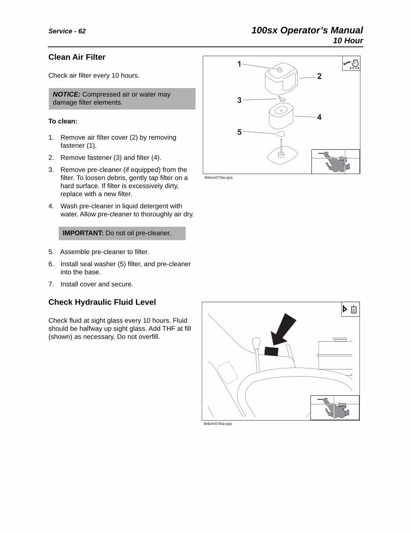
Clean Air Filter
Check air filter every 10 hours.
To clean:
1. Remove air filter cover (2) by removing fastener (1).
2. Remove fastener (3) and filter (4).
3. Remove pre-cleaner (if equipped) from the filter. To loosen debris, gently tap filter on a hard surface. If filter is excessively dirty, replace with a new filter.
4. Wash pre-cleaner in liquid detergent with water. Allow pre-cleaner to thoroughly air dry.
5. Assemble pre-cleaner to filter.
6. Install seal washer (5) filter, and pre-cleaner into the base.
7. Install cover and secure.
Check Hydraulic Fluid Level
Check fluid at sight glass every 10 hours. Fluid should be halfway up sight glass. Add THF at fill (shown) as necessary. Do not overfill.
NOTICE: Compressed air or water may damage filter elements.
IMPORTANT: Do not oil pre-cleaner.
t44om015w.eps
1
3
5
2
4
t44om016w.eps
100sx Operator’s Manual Service - 6310 Hour
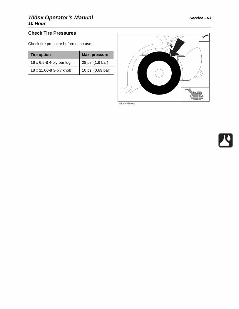
Check Tire Pressures
Check tire pressure before each use.
Tire option Max. pressure
16 x 6.5-8 4-ply bar lug 28 psi (1.9 bar)
18 x 11.00-8 3-ply knob 10 psi (0.69 bar)
t44om017w.eps

Service - 64 100sx Operator’s Manual10 Hour
Check Hydraulic Hoses
Check hydraulic hoses for leaks every 10 hours.
Fluid or air pressure could pierce skin and cause injury or death. Stay away. Escaping pressurized fluid can cause injury or pierce skin and poison.
To help avoid injury:
• Before disconnecting a hydraulic line, turn engine off and operate all controls to relieve pressure. Lower, block, or support any raised component with a hoist. Cover connection with heavy cloth and loosen connector nut slightly to relieve residual pressure. Catch all fluid in a container.
• Before using system, check that all connections are tight and all lines are undamaged.
• Use a piece of cardboard or wood, rather than hands, to search for leaks. Fluid leaks can be hard to detect.
• Wear protective clothing, including gloves and eye protection.
If you are injured, seek immediate medical attention from a doctor familiar with this type of injury.
100sx Operator’s Manual Service - 6550 Hour
50 Hour
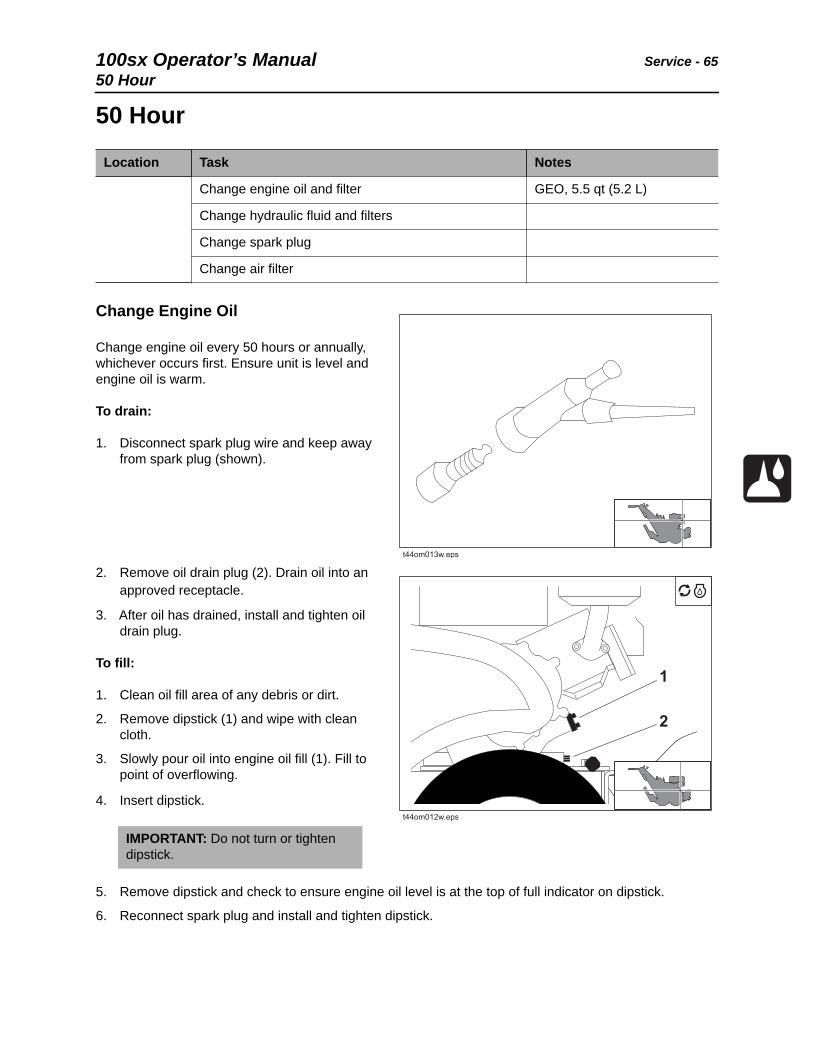
Change Engine Oil
Change engine oil every 50 hours or annually, whichever occurs first. Ensure unit is level and engine oil is warm.
To drain:
1. Disconnect spark plug wire and keep away from spark plug (shown).
2. Remove oil drain plug (2). Drain oil into an approved receptacle.
3. After oil has drained, install and tighten oil drain plug.
To fill:
1. Clean oil fill area of any debris or dirt.
2. Remove dipstick (1) and wipe with clean cloth.
3. Slowly pour oil into engine oil fill (1). Fill to point of overflowing.
4. Insert dipstick.
5. Remove dipstick and check to ensure engine oil level is at the top of full indicator on dipstick.
6. Reconnect spark plug and install and tighten dipstick.
Location Task Notes
Change engine oil and filter GEO, 5.5 qt (5.2 L)
Change hydraulic fluid and filters
Change spark plug
Change air filter
IMPORTANT: Do not turn or tighten dipstick.
t44om013w.eps
t44om012w.eps
1
2
Service - 66 100sx Operator’s Manual50 Hour
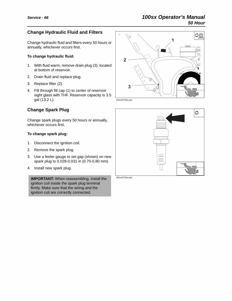
Change Hydraulic Fluid and Filters
Change hydraulic fluid and filters every 50 hours or annually, whichever occurs first.
To change hydraulic fluid:
1. With fluid warm, remove drain plug (3), located at bottom of reservoir.
2. Drain fluid and replace plug.
3. Replace filter (2).
4. Fill through fill cap (1) to center of reservoir sight glass with THF. Reservoir capacity is 3.5 gal (13.2 L).
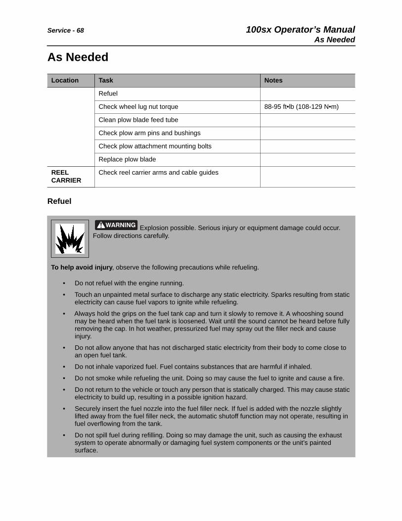
Change Spark Plug
Change spark plugs every 50 hours or annually, whichever occurs first.
To change spark plug:
1. Disconnect the ignition coil.
2. Remove the spark plug.
3. Use a feeler gauge to set gap (shown) on new spark plug to 0.028-0.031 in (0.70-0.80 mm)
4. Install new spark plug.
IMPORTANT: When reassembling, install the ignition coil inside the spark plug terminal firmly. Make sure that the wiring and the ignition coil are correctly connected.
t44om018w.eps
1
2
3
t44om019w.eps

100sx Operator’s Manual Service - 6750 Hour
Change Air Filter
Change air filter every 50 hours or annually, whichever occurs first.
To change:
1. Remove air filter cover (2) by removing fastener (1).
2. Remove fastener (3) and filter (4).
3. Remove pre-cleaner (if equipped) from the filter.
4. Replace air filter and pre-cleaner.
5. Assemble pre-cleaner to filter.
6. Install seal washer (5) filter, and pre-cleaner into the base.
7. Install cover and secure.
NOTICE: Compressed air or water may damage filter elements.
t44om015w.eps
1
3
5
2
4
Service - 68 100sx Operator’s ManualAs Needed
As Needed
Refuel
Location Task Notes
Refuel
Check wheel lug nut torque 88-95 ft•lb (108-129 N•m)
Clean plow blade feed tube
Check plow arm pins and bushings
Check plow attachment mounting bolts
Replace plow blade
REEL CARRIER
Check reel carrier arms and cable guides
Explosion possible. Serious injury or equipment damage could occur. Follow directions carefully.
To help avoid injury, observe the following precautions while refueling.
• Do not refuel with the engine running.
• Touch an unpainted metal surface to discharge any static electricity. Sparks resulting from static electricity can cause fuel vapors to ignite while refueling.
• Always hold the grips on the fuel tank cap and turn it slowly to remove it. A whooshing sound may be heard when the fuel tank is loosened. Wait until the sound cannot be heard before fully removing the cap. In hot weather, pressurized fuel may spray out the filler neck and cause injury.
• Do not allow anyone that has not discharged static electricity from their body to come close to an open fuel tank.
• Do not inhale vaporized fuel. Fuel contains substances that are harmful if inhaled.
• Do not smoke while refueling the unit. Doing so may cause the fuel to ignite and cause a fire.
• Do not return to the vehicle or touch any person that is statically charged. This may cause static electricity to build up, resulting in a possible ignition hazard.
• Securely insert the fuel nozzle into the fuel filler neck. If fuel is added with the nozzle slightly lifted away from the fuel filler neck, the automatic shutoff function may not operate, resulting in fuel overflowing from the tank.
• Do not spill fuel during refilling. Doing so may damage the unit, such as causing the exhaust system to operate abnormally or damaging fuel system components or the unit’s painted surface.

100sx Operator’s Manual Service - 69As Needed
Refuel unit as needed. To refuel:
1. Turn engine switch off and let the engine cool for 3-5 min.
2. Open fuel cap (shown).
3. Insert fuel nozzle and add fuel.
4. Install fuel cap.
Check Wheel Lug Nut Torque
Check wheel lug nut torque before each use. Tighten to 88-95 ft•lb (108-129 N•m).
Clean Plow Feed Tube
Clean feed tube (shown) every 10 hours.
t44om021w.eps
t44om026w.eps
t44om020w.eps
Service - 70 100sx Operator’s ManualAs Needed
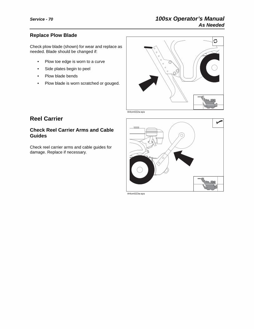
Replace Plow Blade
Check plow blade (shown) for wear and replace as needed. Blade should be changed if:
• Plow toe edge is worn to a curve
• Side plates begin to peel
• Plow blade bends
• Plow blade is worn scratched or gouged.
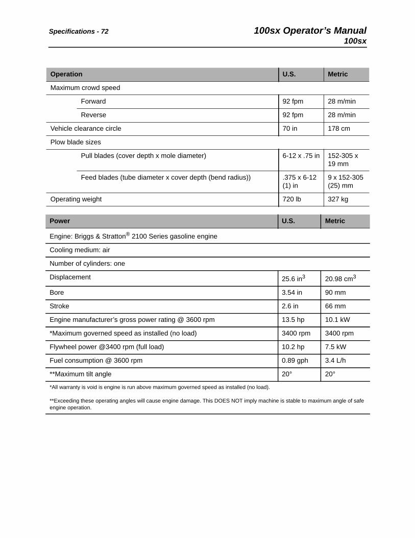
Reel Carrier
Check Reel Carrier Arms and Cable Guides
Check reel carrier arms and cable guides for damage. Replace if necessary.
t44om022w.eps
t44om023w.eps

100sx Operator’s Manual Specifications - 71100sx
Specifications100sx
Dimensions * U.S. Metric
H1 Operating height 41 in 104 cm
A3’ Angle of departure without blade 50° 50°
L1 Maximum length without reel carrier 70 in 178 cm
L2 Maximum length with reel carrier 86.5 in 220 cm
W1 Plow vehicle width 35 in 89 cm
A’ Maximum depth 13 in 33 cm
A Maximum cover depth 12 in 30 cm
t44om025w.eps
Specifications - 72 100sx Operator’s Manual100sx
Operation U.S. Metric
Maximum crowd speed
Forward 92 fpm 28 m/min
Reverse 92 fpm 28 m/min
Vehicle clearance circle 70 in 178 cm
Plow blade sizes
Pull blades (cover depth x mole diameter) 6-12 x .75 in 152-305 x 19 mm
Feed blades (tube diameter x cover depth (bend radius)) .375 x 6-12 (1) in
9 x 152-305 (25) mm
Operating weight 720 lb 327 kg
Power U.S. Metric
Engine: Briggs & Stratton® 2100 Series gasoline engine
Cooling medium: air
Number of cylinders: one
Displacement 25.6 in3 20.98 cm3
Bore 3.54 in 90 mm
Stroke 2.6 in 66 mm
Engine manufacturer’s gross power rating @ 3600 rpm 13.5 hp 10.1 kW
*Maximum governed speed as installed (no load) 3400 rpm 3400 rpm
Flywheel power @3400 rpm (full load) 10.2 hp 7.5 kW
Fuel consumption @ 3600 rpm 0.89 gph 3.4 L/h
**Maximum tilt angle 20° 20°
*All warranty is void is engine is run above maximum governed speed as installed (no load).
**Exceeding these operating angles will cause engine damage. This DOES NOT imply machine is stable to maximum angle of safe engine operation.

100sx Operator’s Manual Specifications - 73100sx
Unless otherwise specified, all figures are for standard equipment only.
Specifications are called out according to SAE recommended procedures. Specifications are general and subject to change without notice. If exact measurements are required, equipment should be weighed and measured. Due to selected options, delivered equipment may not necessarily match that described.
Hydraulic System U.S. Metric
Ground drive pump capacity @ 3600 rpm, relief valve setting @ 2,000 psi 2.2 gpm 8.3 L/min
Ground drive pump displacement/revolution .223 in3 .556 cm3
Ground drive motor displacement/revolution 9.6 in3 157 cm3
Directional control valve type: open center
Delivery capacity 10 gpm 37.8 L/min
System relief valve setting 2500 psi 172.4 bar
Fluid Capacities U.S. Metric
Fuel tank 1.8 gal 6.8 L
Hydraulic reservoir 3.5 gal 13.2 L
Power Train
Ground drive transmission: hydrostatic, infinitely variable forward and reverse, 3:1 chain drive from motor to axle
Tires:
16 x 6.5-8 4-ply bar lug
18 x 11.00-8 3-ply knob
Drive line system: belts and sheaves
Vibratory mechanism: eccentric shaft
Noise Levels
Operator 91 dBA sound pressure per ISO 6394
Exterior 104 dBA sound power per ISO 6393
Vibration
Average vibration transmitted to the operator’s hand during normal trenching operation is 15.2 m/sec2.

Specifications - 74 100sx Operator’s Manual100sx

100sx Operator’s Manual Support - 75Procedure
Support
Procedure
Notify your dealer immediately of any malfunction or failure of Ditch Witch® equipment.
Always give model, serial number, and approximate date of your equipment purchase. This information should be recorded and placed on file by the owner at the time of purchase.
Return damaged parts to dealer for inspection and warranty consideration if in warranty time frame.
Order genuine Ditch Witch replacement or repair parts from your authorized Ditch Witch dealer. Use of another manufacturer's parts may void warranty consideration.
Resources
Publications
Contact your Ditch Witch dealer for publications and videos covering safety, operation, service, and repair of your equipment.
Ditch Witch® Training
For information about on-site, individualized training, contact your Ditch Witch dealer.

Warranty - 76 100sx Operator’s Manual
Warranty
Ditch Witch® Equipment and Replacement PartsLimited Warranty Policy
Subject to the limitation and exclusions herein, free replacement parts will be provided at any authorized Ditch Witch dealership for any Ditch Witch equipment or parts manufactured by The Charles Machine Works, Inc. (CMW) that fail due to a defect in material or workmanship within one (1) year of first commercial use. Free labor will be provided at any authorized Ditch Witch dealership for installation of parts under this warranty during the first year following “initial commercial” use of the serial-numbered Ditch Witch equipment on which it is installed. The customer is responsible for transporting their equipment to an authorized Ditch Witch dealership for all warranty work.
Exclusions from Product Warranty• All incidental or consequential damages.
• All defects, damages, or injuries caused by misuse, abuse, improper installation, alteration, neglect, or uses other than those for which products were intended.
• All defects, damages, or injuries caused by improper training, operation, or servicing of products in a manner inconsistent with manufacturer’s recommendations.
• All engines and engine accessories (these are covered by original manufacturer’s warranty).
• Tires, belts, and other parts which may be subject to another manufacturer’s warranty (such warranty will be available to purchaser).
• ALL IMPLIED WARRANTIES NOT EXPRESSLY STATED HEREIN, INCLUDING ANY WARRANTY OF FITNESS FOR A PARTICULAR PURPOSE AND MERCHANTABILITY.
IF THE PRODUCTS ARE PURCHASED FOR COMMERCIAL PURPOSES, AS DEFINED BY THE UNIFORM COMMERCIAL CODE, THEN THERE ARE NO WARRANTIES WHICH EXTEND BEYOND THE FACE HEREOF AND THERE ARE NO IMPLIED WARRANTIES OF ANY KIND WHICH EXTEND TO A COMMERCIAL BUYER. ALL OTHER PROVISIONS OF THIS LIMITED WARRANTY APPLY INCLUDING THE DUTIES IMPOSED.
Ditch Witch products have been tested to deliver acceptable performance in most conditions. This does not imply they will deliver acceptable performance in all conditions. Therefore, to assure suitability, products should be operated under anticipated working conditions prior to purchase.
Defects will be determined by an inspection within thirty (30) days of the date of failure of the product or part by CMW or its authorized dealer. CMW will provide the location of its inspection facilities or its nearest authorized dealer upon inquiry. CMW reserves the right to supply remanufactured replacements parts under this warranty as it deems appropriate.
Extended warranties are available upon request from your local Ditch Witch dealer or CMW.
Some states do not allow exclusion or limitation of incidental or consequential damages, so above limitation of exclusion may not apply. Further, some states do not allow exclusion of or limitation of how long an implied warranty lasts, so the above limitation may not apply. This limited warranty gives product owner specific legal rights and the product owner may also have other rights which vary from state to state.
For information regarding this limited warranty, contact CMW’s Product Support department, P.O. Box 66, Perry, OK 73077-0066, or contact your local Ditch Witch dealer.
First version: 1/91; Latest version: 11/11


100sx Operator’s Manual Service Record - 79
Service Record
Service Performed Date Hours

Service Record - 80 100sx Operator’s Manual
Service Performed Date Hours