Embed Size (px)
Citation preview
PNNL-15444
100/300 Areas Aquifer Tube Task: Annual Sampling for Fiscal Year 2006, Hanford Site, Washington A Letter Report Prepared by R. E. Peterson M. J. Hartman Pacific Northwest National Laboratory Richland, Washington R. F. Raidl J. V. Borghese Fluor Hanford, Inc. Richland, Washington Prepared for the U.S. Department of Energy under Contract DE-AC05-76RL01830
DISCLAIMER This report was prepared as an account of work sponsored by an agency of the United States Government. Reference herein to any specific commercial product, process, or service by trade name, trademark, manufacturer, or otherwise does not necessarily constitute or imply its endorsement, recommendation, or favoring by the United States Government or any agency thereof, or Battelle Memorial Institute.
PACIFIC NORTHWEST NATIONAL LABORATORY operated by BATTELLE
for the UNITED STATES DEPARTMENT OF ENERGY
under Contract DE-AC05-76RL01830
Printed in the United States of America
Available to DOE and DOE contractors from the Office of Scientific and Technical Information, P.O. Box 62, Oak Ridge, TN 37831;
prices available from (615) 576-8401.
Available to the public from the National Technical Information Service, U.S. Department of Commerce, 5285 Port Royal Rd., Springfield, VA 22161
This document was printed on recycled paper.

PNNL-15444
100/300 Areas Aquifer Tube Task: Annual Sampling for Fiscal Year 2006, Hanford Site, Washington R. E. Peterson M. J. Hartman R. F. Raidl J. V. Borghese October 2005 Prepared for the U.S. Department of Energy under Contract DE-AC05-76RL01830 Pacific Northwest National Laboratory Richland, Washington
This letter report has been prepared to provide the U.S. Department of Energy, U.S. Environmental Protection Agency, Washington State Department of Ecology, and Hanford Site contractors with logistical information pertaining to the use of certain environmental monitoring sites. It is not intended for general distribution beyond that audience.

A. L. Boyd

iii
Contents
1.0 Introduction ................................................................................................................................... 1 2.0 Changes from Previous Fiscal Year .............................................................................................. 1 3.0 Schedule ........................................................................................................................................ 2 4.0 Requirements ................................................................................................................................. 2 5.0 Bibliography .................................................................................................................................. 3 5.1 References Cited ................................................................................................................... 3 5.2 Aquifer Tube Data Summaries.............................................................................................. 4 Appendix A – Draft Procedures for Field Sampling Activities: Aquifer Tubes................................... A.1
Table
1 Schedule for Sampling Aquifer Tubes Along the 100/300 Areas Shoreline Segments During Fiscal Year 2006................................................................................................................ 6
Figures
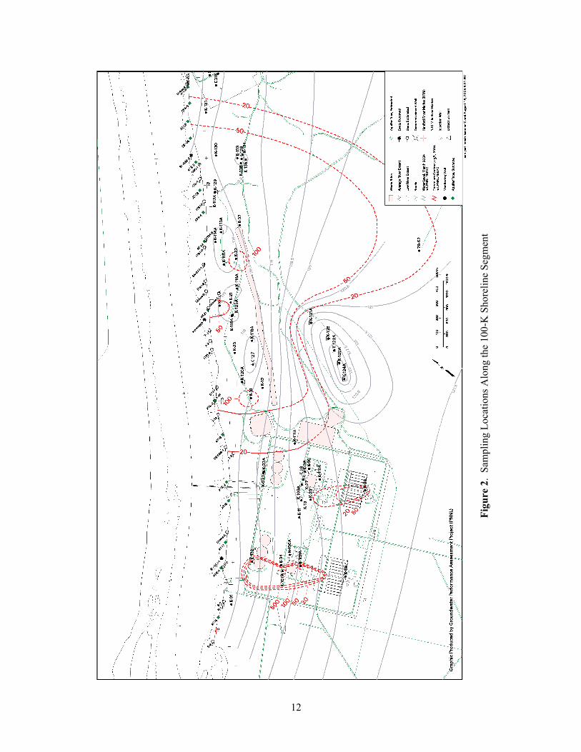
1 Sampling Locations Along the 100-B Shoreline Segment ............................................................ 11 2 Sampling Locations Along the 100-K Shoreline Segment ............................................................ 12 3 Sampling Locations Along the 100-N Shoreline Segment ............................................................ 13 4 Sampling Locations Along the 100-D Shoreline Segment ............................................................ 14 5 Sampling Locations Along the 100-H Shoreline Segment ............................................................ 15 6 Sampling Locations Along the 100-F Shoreline Segment............................................................. 16 7 Sampling Locations Along the 100-F Slough Shoreline Segment ................................................ 17 8 Sampling Locations Along the Sitewide Plume Shoreline Segment ............................................. 18 9 Sampling Locations Along the 300 Area Shoreline Segment ....................................................... 19

1
1.0 Introduction
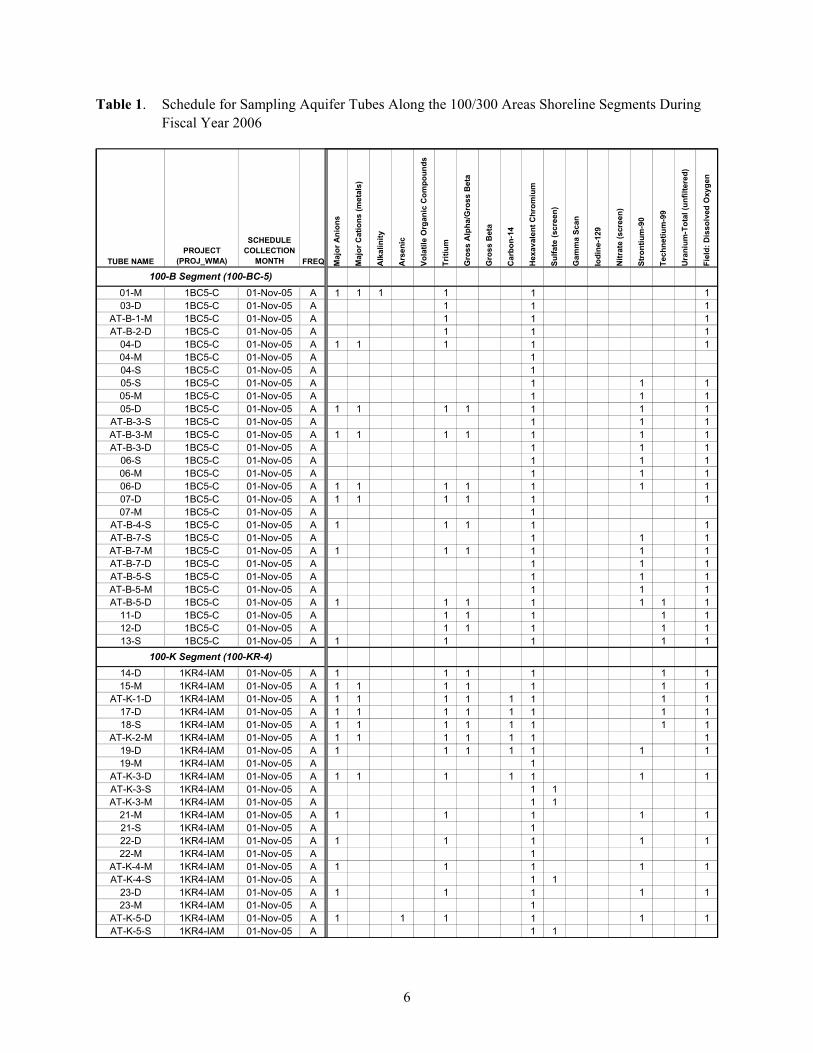
Preparations are underway for field activities associated with the annual sampling of the aquifer tube network along the Hanford Site’s Columbia River shoreline. A meeting was held on August 22, 2005, where representatives from Pacific Northwest National Laboratory (PNNL) and Fluor Hanford, Inc. (FHI) presented a proposed sampling and analysis schedule to U.S. Department of Energy (DOE), U.S. Envi-ronmental Protection Agency (EPA), and Washington State Department of Ecology (Ecology) represen-tatives. Following discussion and concurrence with the general strategy for use of the tubes, it was agreed that a detailed list of sites would be prepared by PNNL and distributed to the unit managers for their concurrence prior to the end of September 2005. (Note: This distribution occurred during the 300 Area Unit Managers Meeting on September 20 and during the 100 Areas Unit Managers Meeting on September 22). Table 1 contains the detailed lists of sites to be sampled and analyses to be performed.
The planning, scheduling, and analytical laboratory activities are coordinated within PNNL’s Ground-water Performance Assessment Project (groundwater project). Field activities are coordinated through PNNL’s Surface Environmental Surveillance Project (SESP). In additional to sampling aquifer tubes, SESP conducts annual sampling tasks at riverbank springs and river water transects. Managing the complex logistics associated with these three tasks, which includes uncertainty created by river discharge conditions, entails flexibility in the exact schedule for their completion.
Background information on the aquifer tube network and its monitoring objectives can be found in the description of work to install the majority of the tubes (Peterson et al. 1997) and the completion report for that installation project (Peterson et al. 1998). A list of data reports prepared for the network is provided in the bibliography section. The analytical results for samples collected from tubes are stored in the Hanford Site’s environmental database (Hanford Environmental Information System [HEIS]).
2.0 Changes from Previous Fiscal Year
The planned schedule for aquifer tubes along the 100/300 Areas of the Hanford Reach remains similar to that prepared for fiscal year (FY) 2005. The number of tube sites to be visited and number of analyses to be performed are approximately the same, although minor adjustments have been made in response to updated interpretations and several new information needs:
• More data are being collected on the vertical distribution of some constituents (e.g., hexavalent chromium at 100-K, 100-D, and 100-H Areas; strontium-90 at 100-B Area; and uranium at 300 Area) to more accurately describe the plumes near their location of discharge to the riverbed.
• Additional analyses have been added to better characterize conditions downgradient of certain treatability tests, or planned tests (e.g., greater focus on anions downgradient of the In Situ Redox Manipulation barrier at 100-D Area and the calcium polysulfide injection test at 100-K Area).
• More frequent field measurements of dissolved oxygen are being made to better characterize the geochemical environment near the groundwater/river interface.

2
Transfer of the aquifer tube work scope from the environmental restoration contractor to PNNL occurred in 2002.1 PNNL field activity procedures are being updated to include field activities associated with collecting samples from the tubes. When finalized, these procedures will be formally adopted within the SESP procedure manual (PNNL 2004). The draft procedures are included as an appendix to this document. Comments may be forwarded to R. E. Peterson at PNNL.
3.0 Schedule
Existing sampling and analysis plans for monitoring groundwater near the Columbia River generally specify an annual sampling event to be conducted during the fall months. The period mid-October to mid-November offers an excellent opportunity for shoreline work along the 100 Areas because the river stage is held low during the daylight hours (water is released during the night hours). Unfortunately, this presents a problem for work along the 300 Area shoreline because the 8-hour time lag from Priest Rapids Dam causes the 300 Area shoreline to be underwater during the normal daylight working hours. As a result, it is not always possible to adhere to the exact planned schedule for collecting samples.
The FY 2006 working schedule for collecting samples from aquifer tubes contains the following target dates for starting activities along the various shoreline segments, which approximate groundwater operable units (identified in parentheses):
• October: 100-D (100-HR-3D) and 100-H (100-HR-3H) Areas • November: 100-K (100-KR-4) and 100-B (100-BC-5) Areas • December: 300 Area (300-FF-5) and the Hanford town site (200-PO-1).
During this period, a bi-weekly report will be prepared that describes the status of field activities, planned activities, and results entered into the HEIS database. This report will be distributed via email by R. E. Peterson ([email protected]). Results are discussed in the annual groundwater report.
4.0 Requirements
Nearly all use of the aquifer tube network is occurring as part of monitoring, characterization, and interim action performance evaluation activities conducted under the Comprehensive Environmental Response, Compensation, and Liability Act (CERCLA) program. Use of some tubes to support various research projects is also underway. Use of the aquifer tube network for CERCLA investigations is described in a sampling and analysis plan (SAP) (DOE-RL 2000). The SAP describes the characteristics of the tubes and the general sampling and analysis requirements. It contains information on contaminants of concern, data quality objectives, a quality assurance project plan, field sampling plan, and health and safety information. The plan also specifies that a meeting of the Tri-Parties (DOE, EPA, and Ecology) be
1 Letter #CC02-0977, U.S. Department of Energy to Pacific Northwest National Laboratory, “Workscope Assigned to PNNL by RL to Support the Hanford Site Groundwater Protection Program,” dated September 1, 2002.

3
held each year to reach consensus on the current year’s list of sites to be sampled and the analyses to be performed. This report satisfies the requirement for documenting the annual update to the SAP.
Refinements to the lists are made annually in response to (a) new or changing interpretations, (b) installation of new sites, and/or (c) loss of some sites because they no longer yield water or have been destroyed. For previous years, concurrence among the Tri-Parties for the annual refinements has been documented either by a sampling analysis instruction for years prior to 2004 (e.g., Raidl 2003) or by a memorandum to the administrative record via a 100 Areas Unit Managers Meeting (post-2004).
For groundwater operable units that do not currently include active remediation of groundwater (i.e., only continued monitoring and characterization are underway), aquifer tube use requirements are also contained in operable-unit-specific SAPs:
• 100-BC-5: DOE-RL (2004a). (Note: Additional use of the tubes along the 100-B segment occurred during FY 2004 and FY 2005 to support the 100-B/C Pilot Project Risk Assessment.)
• 100-FR-3: DOE-RL (2004b).
• 200-PO-1: DOE-RL (2005). (Note: Some of the tubes in this area were refurbished during winter 2004; others could not be located.)
• 300-FF-5: DOE-RL (2002). (Note: This plan was prepared prior to the installation of aquifer tubes in February 2004. However, installation and use of the tubes was anticipated in the plan.)
For those operable units where aquifer tubes are used to support interim remedial actions involving groundwater (i.e., 100-NR-2, 100-KR-4, and 100-HR-3), general use requirements are described in the aquifer tube SAP (DOE-RL 2000). The list of tube sites and analyses to be performed for these operable units are included in the 100/300 Areas annual Tri-Party review of tube use, i.e., the schedules contained in this letter report. (Note: The tubes recently installed along the 100-N segment of shoreline are being sampled as part of the 100-NR-2 Rebound Study and are not included in the 100/300 Areas tube schedule.)
The schedule for FY 2006 is similar to that prepared for FY 2005 with only minor adjustments to the analytical suites. Table 1 reflects the updated list of sites to be sampled under all published monitoring plans and as a result of discussions at the August 22, 2005, meeting of the Tri-Parties. The individual tubes listed are those that produced samples most representative of groundwater during previous sampling events. Depending on current conditions, an alternative tube may be used during FY 2006 at a particular site. Location maps for each of the shoreline segments covered by the tube network are shown in Figures 1 through 9.
5.0 Bibliography
5.1 References Cited
Comprehensive Environmental Response, Compensation, and Liability Act. 1980. Public Law 96-150, as amended, 94 Stat. 2767, 42 USC 9601 et seq.
4
DOE-RL. 2000. Sampling and Analysis Plan for Aquifer Sampling Tubes. DOE/RL-2000-59, Rev. 0, prepared by CH2M HILL Hanford, Inc. for U.S. Department of Energy, Richland, Washington.
DOE-RL. 2002. 300-FF-5 Operable Unit Sampling and Analysis Plan. DOE/RL-2002-11, Rev. 0, prepared by CH2M HILL Hanford, Inc. for U.S. Department of Energy, Richland, Washington.
DOE-RL. 2004a. 100-BC-5 Operable Unit Sampling and Analysis Plan. DOE/RL-2003-38, Rev. 1, prepared by MJ Hartman, Pacific Northwest National Laboratory, for U.S. Department of Energy, Richland, Washington.
DOE-RL. 2004b. 100-FR-3 Operable Unit Sampling and Analysis Plan. DOE/RL-2003-49, Rev. 1, prepared by M.J. Hartman, Pacific Northwest National Laboratory, for U.S. Department of Energy, Richland, Washington.
DOE-RL. 2005. Sampling and Analysis Plan for the 200-PO-1 Groundwater Operable Unit. DOE/RL-2003-04, Rev. 1, prepared by JL Lindbergh, Pacific Northwest National Laboratory, for U.S. Department of Energy, Richland, Washington.
Peterson RE, JV Borghese, and DB Erb. 1998. Aquifer Sampling Tube Installation Completion Report: 100 Area and Hanford Townsite Shorelines. BHI-01153, Rev. 0, prepared by CH2M HILL Hanford, Inc. for Bechtel Hanford, Inc., Richland, Washington.
Peterson RE, KL Singleton, and JV Borghese. 1997. Description of Work for Installing Aquifer Sampling Tubes Along the 100 Area and Hanford Townsite Shorelines. BHI-01090, Rev. 0, prepared by CH2M HILL Hanford, Inc. for Bechtel Hanford, Inc., Richland, Washington.
PNNL. 2004. Surface Environmental Surveillance Procedures Manual. PNL-MA-580, Rev. 4, Pacific Northwest National Laboratory, Richland, Washington.
Raidl RF. 2003. Sampling and Analysis Instruction for Aquifer Sampling Tubes Sampling and Installation Fall 2003. WMP-18051, Rev. 0, Fluor Hanford, Inc., Richland, Washington.
5.2 Aquifer Tube Data Summaries
FY 1996: October-November 1995
Hope SJ and RE Peterson. 1996b. Chromium in River Substrate Pore Water and Adjacent Groundwater: 100-D/DR Area, Hanford Site, Washington. BHI-00778, Rev. 0, prepared by CH2M HILL Hanford, Inc. for Bechtel Hanford, Inc., Richland, Washington.
FY 1998: September-November 1997
Peterson RE, JV Borghese, and DB Erb. 1998. Aquifer Sampling Tube Installation Completion Report: 100 Area and Hanford Townsite Shorelines. BHI-01153, Rev. 0, prepared by CH2M HILL Hanford, Inc. for Bechtel Hanford, Inc., Richland, Washington.
FY 1999: October-November 1998 (no report produced)

5
FY 2000: October-November 1999
Lee TA and RF Raidl. 2000. Fall 1999 Aquifer Sampling Tube Results at the 100 Area and Hanford Townsite Shoreline. Environmental Restoration Contractor InterOffice Memorandum No. 078404, May 2000, prepared by CH2M HILL Hanford, Inc. for Bechtel Hanford, Inc., Richland, Washington.
FY 2001: October-November 2000
Raidl RF. 2001. Aquifer Sampling Tubes Data Summary, Fall 2000. BHI-01494, Rev. 0, prepared by CH2M HILL Hanford, Inc. for Bechtel Hanford, Inc., Richland, Washington.
FY 2002: November 2001
Raidl RF. 2002. Aquifer Sampling Tubes Data Summary, Fall 2001. BHI-01624, Rev. 0, prepared by CH2M HILL Hanford, Inc. for Bechtel Hanford, Inc., Richland, Washington.
FY 2003: November 2002-January 2003
Hartman MJ and RE Peterson. 2003. Aquifer Sampling Tube Results for Fiscal Year 2003. PNNL-14444, Pacific Northwest National Laboratory, Richland, Washington.
FY 2004: December 2003-April 2004
(In preparation September 2005—combined report for FY 2004 and FY 2005.)
FY 2005: November 2004-April 2005
(In preparation September 2005—combined report for FY 2004 and FY 2005.)
6
Table 1. Schedule for Sampling Aquifer Tubes Along the 100/300 Areas Shoreline Segments During Fiscal Year 2006
TUBE NAMEPROJECT
(PROJ_WMA)
SCHEDULECOLLECTION
MONTH FREQ Maj
or A
nion
s
Maj
or C
atio
ns (m
etal
s)
Alk
alin
ity
Ars
enic
Vola
tile
Org
anic
Com
poun
ds
Triti
um
Gro
ss A
lpha
/Gro
ss B
eta
Gro
ss B
eta
Car
bon-
14
Hex
aval
ent C
hrom
ium
Sulfa
te (s
cree
n)
Gam
ma
Scan
Iodi
ne-1
29
Nitr
ate
(scr
een)
Stro
ntiu
m-9
0
Tech
netiu
m-9
9
Ura
nium
-Tot
al (u
nfilt
ered
)
Fiel
d: D
isso
lved
Oxy
gen
01-M 1BC5-C 01-Nov-05 A 1 1 1 1 1 103-D 1BC5-C 01-Nov-05 A 1 1 1
AT-B-1-M 1BC5-C 01-Nov-05 A 1 1 1AT-B-2-D 1BC5-C 01-Nov-05 A 1 1 1
04-D 1BC5-C 01-Nov-05 A 1 1 1 1 104-M 1BC5-C 01-Nov-05 A 104-S 1BC5-C 01-Nov-05 A 105-S 1BC5-C 01-Nov-05 A 1 1 105-M 1BC5-C 01-Nov-05 A 1 1 105-D 1BC5-C 01-Nov-05 A 1 1 1 1 1 1 1
AT-B-3-S 1BC5-C 01-Nov-05 A 1 1 1AT-B-3-M 1BC5-C 01-Nov-05 A 1 1 1 1 1 1 1AT-B-3-D 1BC5-C 01-Nov-05 A 1 1 1
06-S 1BC5-C 01-Nov-05 A 1 1 106-M 1BC5-C 01-Nov-05 A 1 1 106-D 1BC5-C 01-Nov-05 A 1 1 1 1 1 1 107-D 1BC5-C 01-Nov-05 A 1 1 1 1 1 107-M 1BC5-C 01-Nov-05 A 1
AT-B-4-S 1BC5-C 01-Nov-05 A 1 1 1 1 1AT-B-7-S 1BC5-C 01-Nov-05 A 1 1 1AT-B-7-M 1BC5-C 01-Nov-05 A 1 1 1 1 1 1AT-B-7-D 1BC5-C 01-Nov-05 A 1 1 1AT-B-5-S 1BC5-C 01-Nov-05 A 1 1 1AT-B-5-M 1BC5-C 01-Nov-05 A 1 1 1AT-B-5-D 1BC5-C 01-Nov-05 A 1 1 1 1 1 1 1
11-D 1BC5-C 01-Nov-05 A 1 1 1 1 112-D 1BC5-C 01-Nov-05 A 1 1 1 1 113-S 1BC5-C 01-Nov-05 A 1 1 1 1 1
14-D 1KR4-IAM 01-Nov-05 A 1 1 1 1 1 115-M 1KR4-IAM 01-Nov-05 A 1 1 1 1 1 1 1
AT-K-1-D 1KR4-IAM 01-Nov-05 A 1 1 1 1 1 1 1 117-D 1KR4-IAM 01-Nov-05 A 1 1 1 1 1 1 1 118-S 1KR4-IAM 01-Nov-05 A 1 1 1 1 1 1 1 1
AT-K-2-M 1KR4-IAM 01-Nov-05 A 1 1 1 1 1 1 119-D 1KR4-IAM 01-Nov-05 A 1 1 1 1 1 1 119-M 1KR4-IAM 01-Nov-05 A 1
AT-K-3-D 1KR4-IAM 01-Nov-05 A 1 1 1 1 1 1 1AT-K-3-S 1KR4-IAM 01-Nov-05 A 1 1AT-K-3-M 1KR4-IAM 01-Nov-05 A 1 1
21-M 1KR4-IAM 01-Nov-05 A 1 1 1 1 121-S 1KR4-IAM 01-Nov-05 A 122-D 1KR4-IAM 01-Nov-05 A 1 1 1 1 122-M 1KR4-IAM 01-Nov-05 A 1
AT-K-4-M 1KR4-IAM 01-Nov-05 A 1 1 1 1 1AT-K-4-S 1KR4-IAM 01-Nov-05 A 1 1
23-D 1KR4-IAM 01-Nov-05 A 1 1 1 1 123-M 1KR4-IAM 01-Nov-05 A 1
AT-K-5-D 1KR4-IAM 01-Nov-05 A 1 1 1 1 1 1AT-K-5-S 1KR4-IAM 01-Nov-05 A 1 1
100-B Segment (100-BC-5)
100-K Segment (100-KR-4)

7
Table 1. (contd)
TUBE NAMEPROJECT
(PROJ_WMA)
SCHEDULECOLLECTION
MONTH FREQ Maj
or A
nion
s
Maj
or C
atio
ns (m
etal
s)
Alk
alin
ity
Ars
enic
Vola
tile
Org
anic
Com
poun
ds
Triti
um
Gro
ss A
lpha
/Gro
ss B
eta
Gro
ss B
eta
Car
bon-
14
Hex
aval
ent C
hrom
ium
Sulfa
te (s
cree
n)
Gam
ma
Scan
Iodi
ne-1
29
Nitr
ate
(scr
een)
Stro
ntiu
m-9
0
Tech
netiu
m-9
9
Ura
nium
-Tot
al (u
nfilt
ered
)
Fiel
d: D
isso
lved
Oxy
gen
AT-K-5-M 1KR4-IAM 01-Nov-05 A 1 1DK-04-2 1KR4-IAM 01-Nov-05 A 1 1 1 1 1DK-04-3 1KR4-IAM 01-Nov-05 A 1 1
25-D 1KR4-IAM 01-Nov-05 A 1 1 1 1AT-K-6-M 1KR4-IAM 01-Nov-05 A 1 1 1 1 1AT-K-6-S 1KR4-IAM 01-Nov-05 A 1 1AT-K-6-D 1KR4-IAM 01-Nov-05 A 1 1
26-D 1KR4-IAM 01-Nov-05 A 1 1 1 126-S 1KR4-IAM 01-Nov-05 A 126-M 1KR4-IAM 01-Nov-05 A 1
DD-50-3 1HR3D-IAM 01-Oct-05 A 1 1 1 1 1DD-50-1 1HR3D-IAM 01-Oct-05 A 1DD-50-2 1HR3D-IAM 01-Oct-05 A 1DD-50-4 1HR3D-IAM 01-Oct-05 A 1DD-49-4 1HR3D-IAM 01-Oct-05 A 1 1 1 1DD-49-1 1HR3D-IAM 01-Oct-05 A 1DD-49-2 1HR3D-IAM 01-Oct-05 A 1DD-49-3 1HR3D-IAM 01-Oct-05 A 1DD-44-4 1HR3D-IAM 01-Oct-05 A 1 1 1 1 1 1 1DD-44-3 1HR3D-IAM 01-Oct-05 A 1DD-43-2 1HR3D-IAM 01-Oct-05 A 1DD-43-3 1HR3D-IAM 01-Oct-05 A 1DD-42-2 1HR3D-IAM 01-Oct-05 A 1 1 1 1DD-41-2 1HR3D-IAM 01-Oct-05 A 1 1 1 1 1 1DD-41-1 1HR3D-IAM 01-Oct-05 A 1DD-41-3 1HR3D-IAM 01-Oct-05 A 1
REDOX-4-6.0 1HR3D-IAM 01-Oct-05 A 1 1 1 1REDOX-4-3.0 1HR3D-IAM 01-Oct-05 A 1REDOX-3-4.6 1HR3D-IAM 01-Oct-05 A 1 1 1 1REDOX-3-3.3 1HR3D-IAM 01-Oct-05 A 1
DD-39-2 1HR3D-IAM 01-Oct-05 A 1 1 1 1 1 1DD-39-1 1HR3D-IAM 01-Oct-05 A 1
REDOX-2-6.0 1HR3D-IAM 01-Oct-05 A 1 1 1 1REDOX-2-3.0 1HR3D-IAM 01-Oct-05 A 1REDOX-1-6.0 1HR3D-IAM 01-Oct-05 A 1 1 1 1 1 1REDOX-1-3.3 1HR3D-IAM 01-Oct-05 A 1
AT-D-1-D 1HR3D-IAM 01-Oct-05 A 1 1 1 1AT-D-1-S 1HR3D-IAM 01-Oct-05 A 1AT-D-1-M 1HR3D-IAM 01-Oct-05 A 1
35-D 1HR3D-IAM 01-Oct-05 A 1 1 1 135-S 1HR3D-IAM 01-Oct-05 A 135-M 1HR3D-IAM 01-Oct-05 A 1
AT-D-4-D 1HR3D-IAM 01-Oct-05 A 1 1 1 1AT-D-4-S 1HR3D-IAM 01-Oct-05 A 1AT-D-4-M 1HR3D-IAM 01-Oct-05 A 1AT-D-2-M 1HR3D-IAM 01-Oct-05 A 1 1 1AT-D-2-S 1HR3D-IAM 01-Oct-05 A 1
36-S 1HR3D-IAM 01-Oct-05 A 1 1 136-M 1HR3D-IAM 01-Oct-05 A 136-D 1HR3D-IAM 01-Oct-05 A 1
AT-D-3-D 1HR3D-IAM 01-Oct-05 A 1 1 1AT-D-3-S 1HR3D-IAM 01-Oct-05 A 1
100-D Segment (100-HR-3-D)

8
Table 1. (contd)
TUBE NAMEPROJECT
(PROJ_WMA)
SCHEDULECOLLECTION
MONTH FREQ Maj
or A
nion
s
Maj
or C
atio
ns (m
etal
s)
Alk
alin
ity
Ars
enic
Vola
tile
Org
anic
Com
poun
ds
Triti
um
Gro
ss A
lpha
/Gro
ss B
eta
Gro
ss B
eta
Car
bon-
14
Hex
aval
ent C
hrom
ium
Sulfa
te (s
cree
n)
Gam
ma
Scan
Iodi
ne-1
29
Nitr
ate
(scr
een)
Stro
ntiu
m-9
0
Tech
netiu
m-9
9
Ura
nium
-Tot
al (u
nfilt
ered
)
Fiel
d: D
isso
lved
Oxy
gen
AT-D-3-M 1HR3D-IAM 01-Oct-05 A 137-D 1HR3D-IAM 01-Oct-05 A 1 1 137-S 1HR3D-IAM 01-Oct-05 A 137-M 1HR3D-IAM 01-Oct-05 A 138-M 1HR3D-IAM 01-Oct-05 A 1 1 138-D 1HR3D-IAM 01-Oct-05 A 1
DD-17-2 1HR3D-IAM 01-Oct-05 A 1 1 1DD-17-3 1HR3D-IAM 01-Oct-05 A 1DD-16-3 1HR3D-IAM 01-Oct-05 A 1DD-16-4 1HR3D-IAM 01-Oct-05 A 1DD-15-3 1HR3D-IAM 01-Oct-05 A 1 1 1DD-15-2 1HR3D-IAM 01-Oct-05 A 1DD-12-4 1HR3D-IAM 01-Oct-05 A 1 1 1DD-12-2 1HR3D-IAM 01-Oct-05 A 1DD-12-3 1HR3D-IAM 01-Oct-05 A 1DD-10-2 1HR3D-IAM 01-Oct-05 A 1DD-10-3 1HR3D-IAM 01-Oct-05 A 1DD-10-4 1HR3D-IAM 01-Oct-05 A 1AT-D-5-D 1HR3D-IAM 01-Oct-05 A 1 1 1AT-D-5-M 1HR3D-IAM 01-Oct-05 A 1DD-08-2 1HR3D-IAM 01-Oct-05 A 1DD-08-3 1HR3D-IAM 01-Oct-05 A 1DD-08-4 1HR3D-IAM 01-Oct-05 A 1DD-06-2 1HR3D-IAM 01-Oct-05 A 1DD-06-3 1HR3D-IAM 01-Oct-05 A 1
43-D 1HR3H-IAM 01-Oct-05 A 1 1 143-M 1HR3H-IAM 01-Oct-05 A 144-D 1HR3H-IAM 01-Oct-05 A 1 1 145-D 1HR3H-IAM 01-Oct-05 A 1 1 145-S 1HR3H-IAM 01-Oct-05 A 145-M 1HR3H-IAM 01-Oct-05 A 1
AT-H-1-D 1HR3H-IAM 01-Oct-05 A 1 1 1 1 1AT-H-1-S 1HR3H-IAM 01-Oct-05 A 1AT-H-1-M 1HR3H-IAM 01-Oct-05 A 1AT-H-2-D 1HR3H-IAM 01-Oct-05 A 1 1 1 1 1AT-H-2-S 1HR3H-IAM 01-Oct-05 A 1AT-H-2-M 1HR3H-IAM 01-Oct-05 A 1AT-H-3-D 1HR3H-IAM 01-Oct-05 A 1 1 1 1 1 1 1AT-H-3-S 1HR3H-IAM 01-Oct-05 A 1
47-M 1HR3H-IAM 01-Oct-05 A 1 1 1 1 147-D 1HR3H-IAM 01-Oct-05 A 1 1 1 1 148-M 1HR3H-IAM 01-Oct-05 A 1 1 1 148-S 1HR3H-IAM 01-Oct-05 A 149-D 1HR3H-IAM 01-Oct-05 A 1 1 149-S 1HR3H-IAM 01-Oct-05 A 149-M 1HR3H-IAM 01-Oct-05 A 150-M 1HR3H-IAM 01-Oct-05 A 1 1 150-S 1HR3H-IAM 01-Oct-05 A 150-D 1HR3H-IAM 01-Oct-05 A 151-M 1HR3H-IAM 01-Oct-05 A 1 1 151-S 1HR3H-IAM 01-Oct-05 A 151-D 1HR3H-IAM 01-Oct-05 A 1
100-H Segment (100-HR-3-H)

9
Table 1. (contd)
TUBE NAMEPROJECT
(PROJ_WMA)
SCHEDULECOLLECTION
MONTH FREQ Maj
or A
nion
s
Maj
or C
atio
ns (m
etal
s)
Alk
alin
ity
Ars
enic
Vola
tile
Org
anic
Com
poun
ds
Triti
um
Gro
ss A
lpha
/Gro
ss B
eta
Gro
ss B
eta
Car
bon-
14
Hex
aval
ent C
hrom
ium
Sulfa
te (s
cree
n)
Gam
ma
Scan
Iodi
ne-1
29
Nitr
ate
(scr
een)
Stro
ntiu
m-9
0
Tech
netiu
m-9
9
Ura
nium
-Tot
al (u
nfilt
ered
)
Fiel
d: D
isso
lved
Oxy
gen
52-S 1HR3H-IAM 01-Oct-05 A 152-M 1HR3H-IAM 01-Oct-05 A 152-D 1HR3H-IAM 01-Oct-05 A 154-S 1HR3H-IAM 01-Oct-05 A 154-M 1HR3H-IAM 01-Oct-05 A 154-D 1HR3H-IAM 01-Oct-05 A 1
62-M 1FR3-C 01-Dec-05 A 1 1 1 1 163-S 1FR3-C 01-Dec-05 A 1 1 1 1 164-M 1FR3-C 01-Dec-05 A 1 1 164-D 1FR3-C 01-Dec-05 A 1 1 1 1 1 165-S 1FR3-C 01-Dec-05 A 1 1 165-M 1FR3-C 01-Dec-05 A 1 1 1 1 1 1
AT-F-1-S 1FR3-C 01-Dec-05 A 1 1 1AT-F-1-M 1FR3-C 01-Dec-05 A 1 1 1AT-F-1-D 1FR3-C 01-Dec-05 A 1 1 1 1 1 1
66-S 1FR3-C 01-Dec-05 A 1 1 166-M 1FR3-C 01-Dec-05 A 1 1 166-D 1FR3-C 01-Dec-05 A 1 1 1 1 1 1 167-M 1FR3-C 01-Dec-05 A 1 1 1 1 168-D 1FR3-C 01-Dec-05 A 1 1 1 1 1 1
AT-F-2-M 1FR3-C 01-Dec-05 A 1 1 1 1 1 1 1AT-F-3-D 1FR3-C 01-Dec-05 A 1 1 1 1 1 1 1
72-D 1FR3-C 01-Dec-05 A 1 1 1 1 1 173-D 1FR3-C 01-Dec-05 A 1 1 1 1 1 1
AT-F-4-D 1FR3-C 01-Dec-05 A 1 1 1 1 1 174-D 1FR3-C 01-Dec-05 A 1 1 1 1 1 175-D 1FR3-C 01-Dec-05 A 1 1 1 1 1 176-D 1FR3-C 01-Dec-05 A 1 1 1 1 1 177-D 1FR3-C 01-Dec-05 A 1 1 1 1 178-D 1FR3-C 01-Dec-05 A 1 1 1 1 180-D 1FR3-C 01-Dec-05 A 1 1 1 1 1 1
81-D 2PO1-C 01-Dec-05 A 1 1 1 1 182-M 2PO1-C 01-Dec-05 A 1 1 1 1 183-D 2PO1-C 01-Dec-05 A 1 1 1 1 184-D 2PO1-C 01-Dec-05 A 1 1 1 1 185-D 2PO1-C 01-Dec-05 A 1 1 1 1 186-D 2PO1-C 01-Dec-05 A 1 1 1 1 1
AT-3-1-D(1) 3FF5-C 01-Dec-05 Q 1 1 1 1 1 1 1 1AT-3-1-M 3FF5-C 01-Dec-05 Q 1 1 1 1AT-3-1-S 3FF5-C 01-Dec-05 Q 1 1 1 1AT-3-2-M 3FF5-C 01-Dec-05 A 1 1 1 1 1 1 1 1AT-3-2-S 3FF5-C 01-Dec-05 A 1 1 1 1AT-3-3-D 3FF5-C 01-Dec-05 Q 1 1 1 1AT-3-3-M 3FF5-C 01-Dec-05 Q 1 1 1 1 1 1 1 1AT-3-3-S 3FF5-C 01-Dec-05 Q 1 1 1 1AT-3-4-D 3FF5-C 01-Dec-05 Q 1 1 1 1AT-3-4-M 3FF5-C 01-Dec-05 Q 1 1 1 1AT-3-4-S 3FF5-C 01-Dec-05 Q 1 1 1 1 1 1 1 1AT-3-5-S 3FF5-C 01-Dec-05 A 1 1 1 1 1 1 1 1AT-3-6-D 3FF5-C 01-Dec-05 A 1
100-F Segment (100-FR-3)
Townsite Segment (200-PO-1)
300 Area Segment (300-FF-5)

10
Table 1. (contd)
TUBE NAMEPROJECT
(PROJ_WMA)
SCHEDULECOLLECTION
MONTH FREQ Maj
or A
nion
s
Maj
or C
atio
ns (m
etal
s)
Alk
alin
ity
Ars
enic
Vola
tile
Org
anic
Com
poun
ds
Triti
um
Gro
ss A
lpha
/Gro
ss B
eta
Gro
ss B
eta
Car
bon-
14
Hex
aval
ent C
hrom
ium
Sulfa
te (s
cree
n)
Gam
ma
Scan
Iodi
ne-1
29
Nitr
ate
(scr
een)
Stro
ntiu
m-9
0
Tech
netiu
m-9
9
Ura
nium
-Tot
al (u
nfilt
ered
)
Fiel
d: D
isso
lved
Oxy
gen
AT-3-6-M 3FF5-C 01-Dec-05 A 1AT-3-6-S 3FF5-C 01-Dec-05 A 1 1 1 1 1 1 1 1AT-3-7-D 3FF5-C 01-Dec-05 A 1AT-3-7-M 3FF5-C 01-Dec-05 A 1 1 1 1 1 1 1 1AT-3-7-S 3FF5-C 01-Dec-05 A 1AT-3-8-D 3FF5-C 01-Dec-05 A 1AT-3-8-M 3FF5-C 01-Dec-05 A 1AT-3-8-S 3FF5-C 01-Dec-05 A 1 1 1 1 1 1 1 1
AT-3-1-D(1) 3FF5-C 01-Mar-06 Q 1 1 1 1 1 1 1 1AT-3-1-M 3FF5-C 01-Mar-06 Q 1 1 1 1AT-3-1-S 3FF5-C 01-Mar-06 Q 1 1 1 1AT-3-3-D 3FF5-C 01-Mar-06 Q 1 1 1 1AT-3-3-M 3FF5-C 01-Mar-06 Q 1 1 1 1 1 1 1 1AT-3-3-S 3FF5-C 01-Mar-06 Q 1 1 1 1AT-3-4-D 3FF5-C 01-Mar-06 Q 1 1 1 1AT-3-4-M 3FF5-C 01-Mar-06 Q 1 1 1 1AT-3-4-S 3FF5-C 01-Mar-06 Q 1 1 1 1 1 1 1 1
AT-3-1-D(1) 3FF5-C 01-Jun-06 Q 1 1 1 1 1 1 1 1AT-3-1-M 3FF5-C 01-Jun-06 Q 1 1 1 1AT-3-1-S 3FF5-C 01-Jun-06 Q 1 1 1 1AT-3-3-D 3FF5-C 01-Jun-06 Q 1 1 1 1AT-3-3-M 3FF5-C 01-Jun-06 Q 1 1 1 1 1 1 1 1AT-3-3-S 3FF5-C 01-Jun-06 Q 1 1 1 1AT-3-4-D 3FF5-C 01-Jun-06 Q 1 1 1 1AT-3-4-M 3FF5-C 01-Jun-06 Q 1 1 1 1AT-3-4-S 3FF5-C 01-Jun-06 Q 1 1 1 1 1 1 1 1
AT-3-1-D(1) 3FF5-C 01-Sep-06 Q 1 1 1 1 1 1 1 1AT-3-1-M 3FF5-C 01-Sep-06 Q 1 1 1 1AT-3-1-S 3FF5-C 01-Sep-06 Q 1 1 1 1AT-3-3-D 3FF5-C 01-Sep-06 Q 1 1 1 1AT-3-3-M 3FF5-C 01-Sep-06 Q 1 1 1 1 1 1 1 1AT-3-3-S 3FF5-C 01-Sep-06 Q 1 1 1 1AT-3-4-D 3FF5-C 01-Sep-06 Q 1 1 1 1AT-3-4-M 3FF5-C 01-Sep-06 Q 1 1 1 1AT-3-4-S 3FF5-C 01-Sep-06 Q 1 1 1 1 1 1 1 1
Abbreviations: Q = Quarterly; A = Annual. Major anions = Bromide, chloride, fluoride, nitrate, nitrite, phosphate, and sulfate. Major cations (metals; filtered samples) = antimony, barium, beryllium, cadmium, calcium, chromium, cobalt, iron, magnesium, manganese, nickel, potassium, silver, sodium, strontium, vanadium, and zinc.Field parameters: The following field parameters are recorded for each tube from which a sample is collected: temperature, pH, specific conductance, and reduction-oxidation potential (“redox” or “ORP”).River conditions: Field parameters and dissolved oxygen content are measured in nearshore river water adjacent to each tube site sampled.
Note: Tube name listed is that most recently sampled (i.e., most representative of groundwater). Depending on FY 2006 conditions, an alternative tube at a specific site may be sampled.

11
Figu
re 1
. Sa
mpl
ing
Loca
tions
Alo
ng th
e 10
0-B
Sho
relin
e Se
gmen
t
12
Figu
re 2
. Sa
mpl
ing
Loca
tions
Alo
ng th
e 10
0-K
Sho
relin
e Se
gmen
t

13
Figu
re 3
. Sa
mpl
ing
Loca
tions
Alo
ng th
e 10
0-N
Sho
relin
e Se
gmen
t

14
Figu
re 4
. Sa
mpl
ing
Loca
tions
Alo
ng th
e 10
0-D
Sho
relin
e Se
gmen
t

15
Figu
re 5
. Sa
mpl
ing
Loca
tions
Alo
ng th
e 10
0-H
Sho
relin
e Se
gmen
t

16
Figu
re 6
. Sa
mpl
ing
Loca
tions
Alo
ng th
e 10
0-F
Shor
elin
e Se
gmen
t

17
Figu
re 7
. Sa
mpl
ing
Loca
tions
Alo
ng th
e 10
0-F
Slou
gh S
hore
line
Segm
ent

18
Figure 8. Sampling Locations Along the Sitewide Plume Shoreline Segment

19
Figu
re 9
. Sa
mpl
ing
Loca
tions
Alo
ng th
e 30
0 A
rea
Shor
elin
e Se
gmen
t

Appendix
Draft Procedures for Field Sampling Activities: Aquifer Tubes

A.1
Appendix
Draft Procedures for Field Sampling Activities: Aquifer Tubes
Introduction Groundwater beneath the Hanford Site discharges to the Columbia River after passing through a zone of groundwater/river water interaction in the vicinity of the shoreline. In this zone of interaction, river water may infiltrate the river bank during periods of high river stage, and layer and/or mix with the approaching groundwater. Contaminants carried by groundwater may become diluted by the infiltrating river water, thus reducing concentrations at locations of exposure, such as riverbank springs and upwelling through the riverbed. Figure 1 illustrates the principal features associated with the zone of interaction, which typically lies beneath the surface riparian zone.
Figure 1. Principal Features and Sampling Sites Associated with the Zone of Interaction
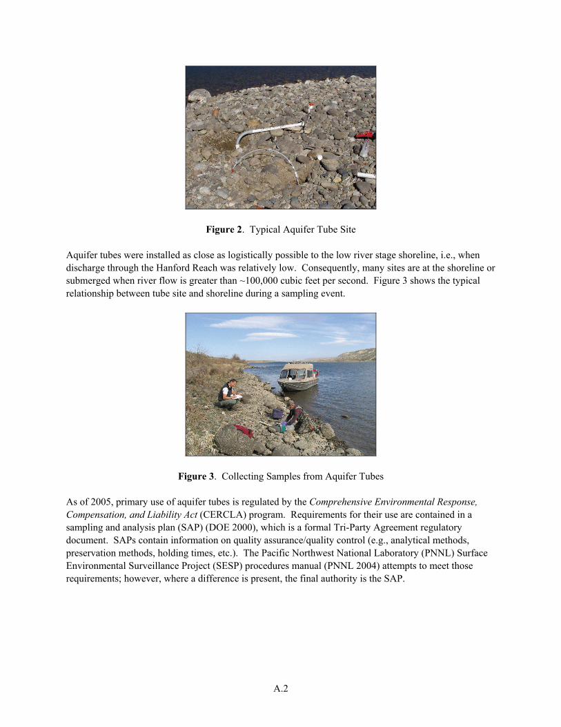
The zone of interaction is monitored by collecting water samples from aquifer tubes, which consist of small diameter plastic tubing that has a 15-centimeter (6-inch) screen mesh at its lower end to act as a sampling port (Peterson et al. 1998). A tube site typically has three separate tubes, each monitoring a different depth below ground surface. Water samples are withdrawn using a portable pump. Aquifer tube sites are located near the low river-stage shoreline, typically along the gravelly portion of the beach. A typical tube site is shown in Figure 2. Most sites consist of three separate tubes, each covered by a short section (~1 meter in length) of white polyvinyl chloride (PVC) pipe, which provides protection from sun and animals. The PVC pipe is covered by cobbles to make the installation less conspicuous. All sites have been surveyed and global positioning system (GPS) receivers are used to return to the sites.
A.2
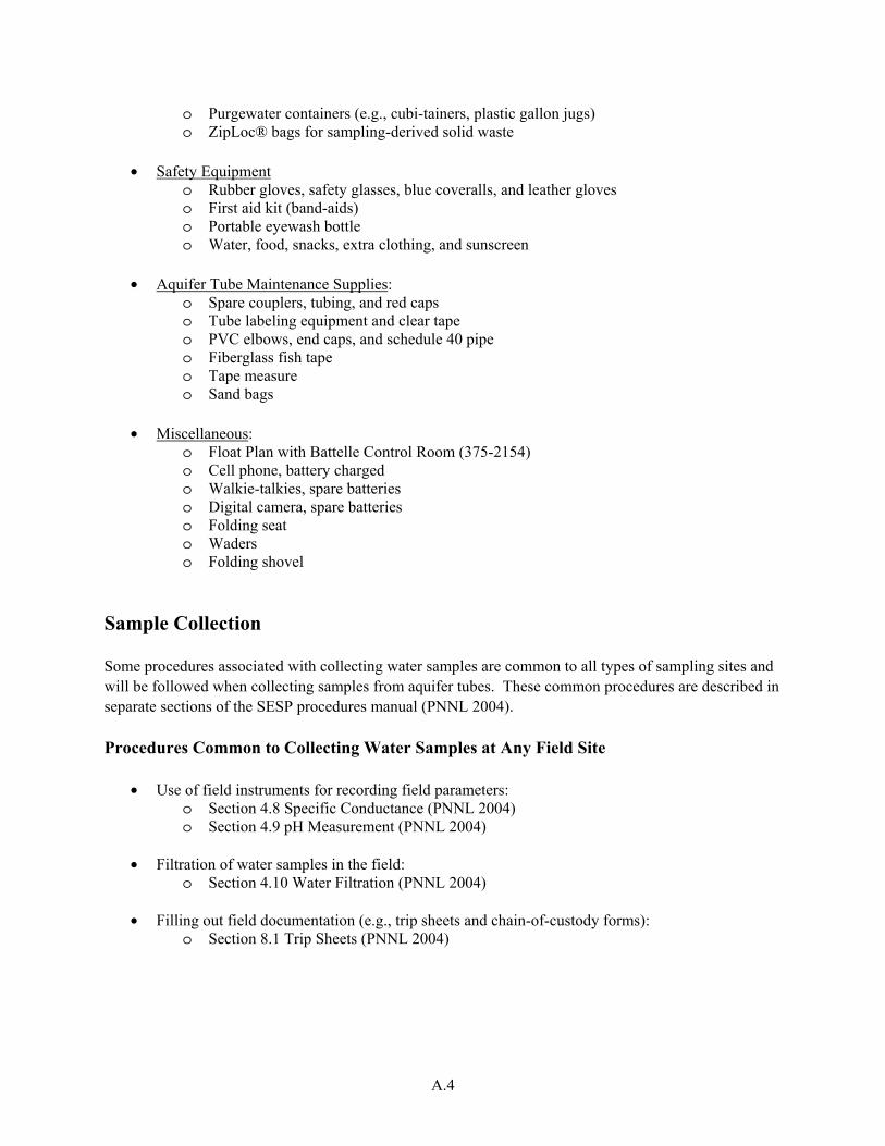
Figure 2. Typical Aquifer Tube Site Aquifer tubes were installed as close as logistically possible to the low river stage shoreline, i.e., when discharge through the Hanford Reach was relatively low. Consequently, many sites are at the shoreline or submerged when river flow is greater than ~100,000 cubic feet per second. Figure 3 shows the typical relationship between tube site and shoreline during a sampling event.
Figure 3. Collecting Samples from Aquifer Tubes As of 2005, primary use of aquifer tubes is regulated by the Comprehensive Environmental Response, Compensation, and Liability Act (CERCLA) program. Requirements for their use are contained in a sampling and analysis plan (SAP) (DOE 2000), which is a formal Tri-Party Agreement regulatory document. SAPs contain information on quality assurance/quality control (e.g., analytical methods, preservation methods, holding times, etc.). The Pacific Northwest National Laboratory (PNNL) Surface Environmental Surveillance Project (SESP) procedures manual (PNNL 2004) attempts to meet those requirements; however, where a difference is present, the final authority is the SAP.

A.3
Personnel Requirements Collecting samples from aquifer tubes may only be conducted by staff who have received training on the relevant sections of this procedures manual, as identified in this section. Personal are to be briefed prior to each day’s field activities on site-specific safety issues, as appropriate to the logistics (e.g., boat or land vehicle operations) and geographic areas involved (e.g., environmental hazards). Staff assigned to aquifer tube sampling will also have been briefed as to (a) the purpose for sampling the tubes, (b) features unique to the tubes, and (c) tube-specific sampling procedures. Equipment The following is a comprehensive list of equipment and supplies associated with aquifer tube activities. Types of activities include: (1) reconnaissance to locate and determine the condition of tubes, (2) mainte-nance and refurbishment, and (3) collection of water samples. Not all listed equipment and supplies are needed for each type of activity. Equipment and Supplies for Aquifer Tube Field Activities
• Aquifer Sampling Tube (AQST) Field Notebook o Pre-departure checklist for equipment and supplies o Field instructions-excerpts from this procedure o Geographic coordinates for tube sites o Shoreline maps o Points-of-contact and phone numbers
• Navigation Equipment
o Global positioning system receiver, batteries charged o Check settings and units: Datum set to NAD83 or WGS84
• Water Withdrawal/Collection Equipment
o Peristaltic pump, battery charged o Tubing for pump (separate tubing for each site) o Spare power pack and connecting wire harness
• Sample Collection Equipment
o Field meter for specific conductance, pH, etc.; calibrated o Dissolved oxygen meter o Sample bottles o Paperwork: Groundwater Sampling Reports (GSRs), sample bottle labels, and Chain-of-
Custody forms (COCs) o High-volume cartridge filters o Clear tape for bottle labels o Security tape for sample bottles o Field sampling cooler with ice o Sharpie® markers, ballpoints, pencils, clipboard
A.4
o Purgewater containers (e.g., cubi-tainers, plastic gallon jugs) o ZipLoc® bags for sampling-derived solid waste
• Safety Equipment
o Rubber gloves, safety glasses, blue coveralls, and leather gloves o First aid kit (band-aids) o Portable eyewash bottle o Water, food, snacks, extra clothing, and sunscreen
• Aquifer Tube Maintenance Supplies:
o Spare couplers, tubing, and red caps o Tube labeling equipment and clear tape o PVC elbows, end caps, and schedule 40 pipe o Fiberglass fish tape o Tape measure o Sand bags
• Miscellaneous:
o Float Plan with Battelle Control Room (375-2154) o Cell phone, battery charged o Walkie-talkies, spare batteries o Digital camera, spare batteries o Folding seat o Waders o Folding shovel
Sample Collection Some procedures associated with collecting water samples are common to all types of sampling sites and will be followed when collecting samples from aquifer tubes. These common procedures are described in separate sections of the SESP procedures manual (PNNL 2004). Procedures Common to Collecting Water Samples at Any Field Site
• Use of field instruments for recording field parameters: o Section 4.8 Specific Conductance (PNNL 2004) o Section 4.9 pH Measurement (PNNL 2004)
• Filtration of water samples in the field: o Section 4.10 Water Filtration (PNNL 2004)
• Filling out field documentation (e.g., trip sheets and chain-of-custody forms): o Section 8.1 Trip Sheets (PNNL 2004)

A.5
Procedures Specific to Collecting Samples from Aquifer Tubes The steps to collect water samples at an aquifer tube site are described below. Primary bullets are mandatory steps; supporting information/optional steps are described using secondary bullets. • Remove PVC protective pipe and note individual tube names, WELL_IDs (i.e., “Bxxxx” or “Cxxxx”
numbers), and depths below ground surface. Verify tube names and WELL_IDs are the same as those on the GSR(s).
o If there is any question as to the identity of individual tubes, draw a sketch on the GSR showing tube layout relative to the river.
o An example GSR form that shows how to record information is included in the Aquifer Sampling Tube Field Notebook.
• Purge each tube until the flow is clear and the specific conductance stabilizes. Record initial specific
conductance values for each tube on the GSR listing the most comprehensive suite of samples. Note flow characteristics from tubes, e.g., low yield, turbid, air bubbles, etc.
o Use a new piece of peristaltic pump tubing for each site (not each tube). o Collect purgewater in cubi-tainers or plastic jugs.
• Select tube for full suite of samples based on the specific conductance values:
o Samples are collected when the specific conductance for water from the tubes is greater than ~160 μS/cm. Do not collect samples if no tube shows a specific conductance value of ~160 μS/cm or higher. For tube(s) that show a specific conductance greater than ~160 μS/cm, select the tube with the highest value for the full suite of samples.
o If the tube with the highest specific conductance is not the tube listed on the GSR having the full suite of analyses (“primary” GSR), change the tube name on that GSR. Modify the other GSR’s for the site, as appropriate.
o Call Bob Peterson (373-9020), Mary Hartman (373-0028), or Greg Patton (376-2027) if there is uncertainty about how to proceed. Skip sampling if none of those individuals can be contacted.
• Verify that labels for sample bottles are consistent with the GSR. If not previously labeled, add labels
to sample bottles. Record date, time-of-sample collection, and collector on bottle labels, and on GSR. • Collect water for the full suite of samples from the tube that shows the highest specific conductance,
i.e., is most representative of groundwater. The GSR will specify whether or not to filter the water prior to filling the sample bottle.
o At some sites, the GSR will specify that samples be collected from all tubes that yield water, regardless of the specific conductance. These data are used in special studies that show the degree of dilution by river water.
o If tube has low yield (e.g., would take an hour or more to collect a 3-liter sample), call Bob Peterson (373-9020), Mary Hartman (373-0028), or Greg Patton (376-2027) for resolution, or skip the sample if none of those individuals can be contacted.
• After collecting all samples, measure and record the field parameters listed on the GSR for the tube.
Normally these will include pH, temperature, specific conductance, dissolved oxygen (DO), and oxidation/reduction potential (ORP).

A.6
• Measure near-shore river water specific conductance, pH, and DO. Record on primary GSR for the tube site.
• Sampling Site Closeout:
o Replace red caps on ends of tubes, replace PVC overpack piping, and cover site with cobbles or sand bags.
o Place solid waste (pump tubing, rubber gloves, filters, etc.) for each tube site in a ZipLoc® bag; label bag with operable unit name, individual tube names, and date.
o Label purgewater container with operable unit name, individual tube names, and date. Purgewater from all sites within a particular groundwater operable unit may be combined.
o Place security tape on sample bottles if field conditions permit, and place bottles in field cooler for transport back to Sigma 5 building.
• Post-field processing and interim storage activities:
o If not done in the field, sampler will place security tape on individual sample bottles or field cooler prior to relinquishing custody.
o Fill out chain-of-custody (COC) forms. o Perform correspondence check between GSR and COC. o Place samples in locked, interim storage or deliver samples to analytical facility. o Ship samples according to required procedures for individual laboratory. o Deliver solid and liquid sampling derived wastes to Fluor Hanford, Inc. per their
instructions (see AQST Field Notebook for current Fluor contact). References
Comprehensive Environmental Response, Compensation, and Liability Act. 1980. Public Law 96-150, as amended, 94 Stat. 2767, 42 USC 9601 et seq.
DOE. 2000. Sampling and Analysis Plan for Aquifer Sampling Tubes. DOE/RL-2000-59, Rev. 0, U.S. Department of Energy, Richland, Washington.
Peterson, R.E., J.V. Borghese, and D.B. Erb. 1998. Aquifer Sampling Tube Installation Completion Report: 100 Area and Hanford Townsite Shorelines. BHI-01153, Rev. 0, Bechtel Hanford, Inc., Richland, Washington.
PNNL. 2004. Surface Environmental Surveillance Procedures Manual. PNL-MA-580, Rev. 4, Pacific Northwest National Laboratory, Richland, Washington.

PNNL-15444
Distr.1
Distribution No. of Copies ONSITE 5 DOE Richland Operations Office KM Thompson A6-38 AC Tortoso (3) A6-38 DC Ward A2-17 2 Fluor Hanford, Inc. JV Borghese E6-35 RF Raidl E6-35 3 U.S. Environmental Protection Agency AL Boyd B1-46 DA Faulk B1-46 LE Gadbois B1-46
No. of Copies Washington Closure Hanford, Inc. SG Weiss H0-23 2 Washington State Department of Ecology D Goswami H0-57 J Price H0-57 9 Pacific Northwest National Laboratory JS Fruchter K6-96 MJ Hartman K6-96 SP Luttrell K6-96 LF Morasch K6-86 GW Patton K6-75 RE Peterson (3) K6-75 VP Vermeul K6-96