Embed Size (px)
Citation preview

1000's Tech Notes & Jumper Manual
Volume 1

1000's Tech Notes & Jumper Manual
Volume 1
Copyright 1993, Micro Systems Copyright 1993, Lightwave Productions
All Rights Reserved. without permission in writing from the publisher.
This book may not be reproduced in any form
Tandy is a trademark of Tandy Corp. All trademarks are registered with their respective companies.
Micro Systems and/or Lightwave Productions is not connected in any way with Tandy Corp. or Radio Shack and are independent companies. without warranty of any kind either expressed or implied, including, but not limited to the implied warranty of fitness fo r a particular purpose. provided within this book is with you. Lightwave Productions and/or its employees will not assume responsibility or liability for any inaccuracies, errors or ommissions, loss, damage caused or alleged to be caused directly or indirectly by this book or any information within this book.
All information in this book is provided "AS ISw1,
The entire risk of using the information Micro Systems and/or
Page - 1

Table Of Contents Pacre
Introduction ....................................... Quick Look At Memory Addressing .................... Expanded and Extended Memory ....................... Original DOS Version Chart ......................... BIOS ROM Chart ..................................... BIOS ROM Information ...............................
1000, 1000A. 1000HD ........................... 1000EX ......................................... 1000HX ........................................ lOOORL and 1000RL-HD .......................... lOOORLX and 1000RLX-HD ........................ 1000RLX-B and 1000RLX-B-HD .................... 1000RSX ....................................... 1000SL ........................................ 1000SX ........................................ 1000TL ........................................ lOOOTL/2 ...................................... lOOOTL/3 ...................................... 1000TX ........................................
CPU Speed and Power Supply Chart ................... Math Co-Processor Chart ............................ Expansion Slot Chart ............................... Base Memory and Total Memory Chart ................. Speed Upgrade Chart ................................
286 Express Board Information ................. Built-In Video Chart ............................... Monitor Type Chart ................................. Standard Floppy Drives f Number Of Drive Bays Chart
High Density Floppy Drive Information ......... Power In Floppy Drive Cable Chart .................. Built-In Floppy Controller and IDE Interface Chart . Serial/Parallel/Other Ports Charts ................. Systems With Special Setup Programs Chart .......... Clock Chip Installation Chart ......................
Clock Chip Software ........................... SLCLK Software ................................ SMWCLOCK Software .............................
Tandy 1000 Interrupts .............................. 1/0 Addresses ...................................... Serial and Parallel Port Addresses ................. Hardware Interrupts ................................ Hard Drives and Hard Card Information .............. Floppy Drive Information ........................... High Density Floppy Drive Setup Information ........ Serial Ports and Modems ............................ VGA Information .................................... Keyboards .......................................... Mice and Trackballs ................................ Turning Off The ROMS ...............................
1000SL/2 ......................................
1 3 5 7 8 9 9 10 10 10 10 10 11 11 12 12 12 13 13 13 14 15 16 17 19 20 22 23 24 25 26 28 30 32 33 35 35 36 37 38 38 39 40 42 43 45 46 46 47 50
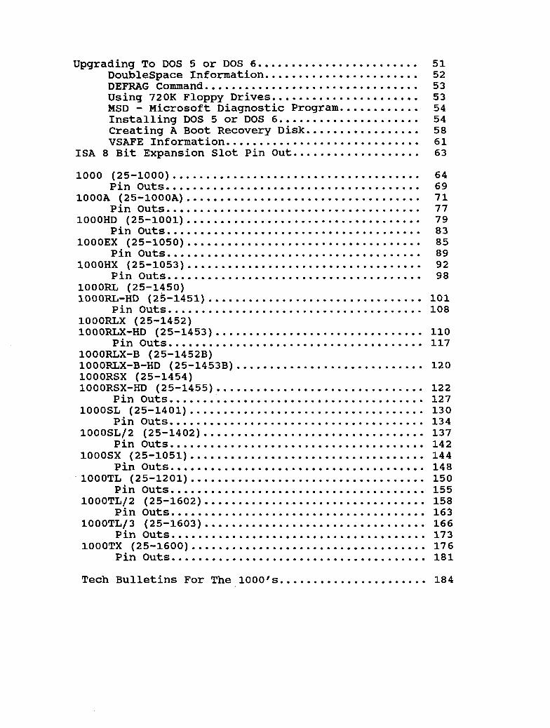
Upgrading To DOS 5 or DOS 6 ........................ 51 Doublespace Information ....................... 52 DEFRAG Command ................................ 53 Using 720K Floppy Drives ...................... 53 Installing DOS 5 or DOS 6 ..................... 54 Creating A Boot Recovery Disk ................. 58 VSAFE Information ............................. 61
ISA 8 Bit Expansion Slot Pin Out ................... 63
MSD - Microsoft Diagnostic Program ............ 54
1000 (25-1000) ..................................... 64
lOOOA (25-1000A) ................................... 71
lOOOHD (25-1001) ................................... 79
lOOOEX (25-1050) ................................... 85
lOOOHX (25-1053) ................................... 92
lOOORL (25-1450) 1000RL-HD (25-1451) ................................ 101
lOOORLX (25-1452) 1000RLX-HD (25-1453) ............................... 110
1000RLX-B (25-1452B) 1000RLX-B-HD (25-1453B) ............................ 120 lOOORSX (25-1454) 1000RSX-HD (25-1455) ............................... 122
Pin Outs ...................................... 127 lOOOSL (25-1401) ................................... 130
Pin Outs ...................................... 134 1000SL/2 (25-1402) ................................. 137
Pin Outs ...................................... 142 lOOOSX (25-1051) ................................... 144
Pin Outs ...................................... 148 -1000TL (25-1201) ................................... 150
Pin Outs ...................................... 155 1000TL/2 (25-1602) ................................. 158
Pin Outs ...................................... 163 1000TL/3 (25-1603) ................................. 166
Pin Outs ...................................... 173 lOOOTX (25-1600) ................................... 176
Pin Outs ...................................... 181
Pin Outs ...................................... 69
Pin Outs ...................................... 77
Pin Outs ...................................... 83
Pin Outs ...................................... 89
Pin Outs ...................................... 98
Pin Outs ...................................... 108
Pin Outs ...................................... 117
Tech Bulletins For The 1000's ...................... 184

Incorrect Chip Installation
ProDer C h i D Installation
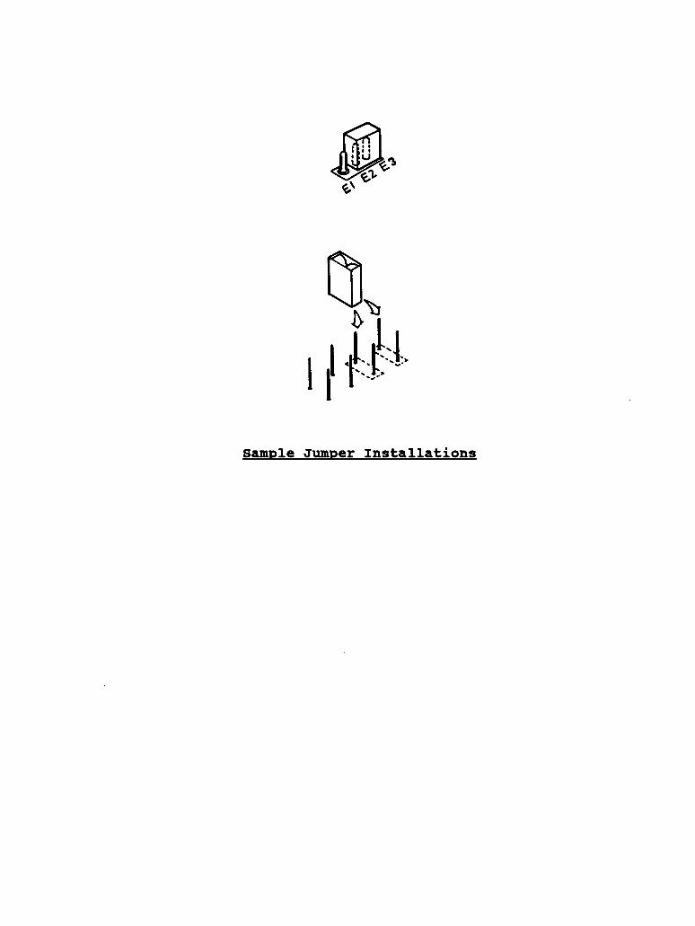
Sample Jumper Installations

T e c h Notes h Jumper Guide For T h e 1000's V o l . 1
Welcome to the Tech Notes 61 Jumper Guide. This is volume 1 in this series. This book is to serve as a reference guide to the 1000's and to provide you with the technical information you will need when upgrading your 1000. Since Tandy introduced the 1000, they have produced over 15 models of the 1000. Please be sure you know exactly which model you have before you start upgrading your system. Please understand this book will give you the technical information and jumper and switch settings when installing upgrades. If you want #@how to" information on installing upgrades into the IOOO's, check out our video, I1Secret's of the 1000's. Vol ill. It will show you how to install upgrades into your system.
The information contained in the video and this book has been gathered over the years from working with the 1000's day in and day out. For some of you, if you find the information contained in'this book too technical, give it time. As you learn by watching the videos and reading this book, it will all come together for you.
As we began to write this book we quickly found out that we would need to split it up into two volumes. This volume will deal primarily with the computer system and motherboard information. Volume 2 will deal more in-depth with the add-on parts such as hard cards, hard drives, more in-depth on floppy drives, modems, video cards, etc. If there is anything that you find incorrect, please drop us a line, with a copy of the page and a note on what may be incorrect. We will include it in future printings of the book.
How T o Use T h i s Book
This book contains a section on each of the 1000's and also contains many quick reference charts. Some information is not listed under the individual computer, but under the quick reference charts or under a specific topic. There is a lot of information that is only listed under the quick reference charts, so be sure to read the notes section under each quick reference chart.
On the following pages we will be referencing several hard drive and floppy drive models. production. Many of the model numbers have been changed. We have included the model number just for reference.
These models may or may not be in
Page - 2

Over the years you probably have heard comments like:
"That requires a trained technician to install it1# or I1You can't run that large of a hard drive in your systemt1 or "There is no way to speed-up your system1# or I8You can't install a high density drive in your 1000nl or llYou have a 1000, we don't carry parts for that systemt1 or ....
The list of excuses go on and on. The truth is, there is a lot of upgrades that you can do to your lOOO!
There are hundreds of third party products that are made especially for the lOOO's! to 500+ meg hard drives to speed upgrades to memory upgrades and many more items.
Everything from high density drives
Well then, why do the sales people make up these excuses? It could be that they don't supply products for your system, so they will tell you that it can't be done. introduce you to a new computer that they say is fully expandable. The truth is, yours is expandable too! You're just not shopping at the right place. available for your system by calling someone who deals in add-on products for your lOOO!
Then they will
You need to check what's really
A Quick Look At The Tandy 1000 Series Of Computers.
then Tandy has produced the lOOOSX, EX, HX, TX, AX, SL, SL/2, TL, TL/2, TL/3, RL, R L X and the RSX. They also produced several other models for Wal-Mart and other stores.
The first model was the 1000, then came the 1000A. Since
The following 1000 models have the 8088 or 8086 chip: 1000, 1000A, SX, EX, HX, SL, SL/2, AX and RL.
The following 1000 models have the 80286 chip: 1000 TX, TL, TL/2, TL/3, and RLX.
The 1000 RSX has the 80386 chip.
The lOOOPC and lOOOAX were some of the computers that Tandy made for other companies. The lOOOPC is like lOOOSL and the lOOOAX is like the 1OOOSX.
A Quick Look At Memory Addressing
The amount of memory that a computer can address is determined by the number of address lines for each processor.
8088/8086 20 address lines 1 Meg Address Limit
Page - 3

80286 80386 80486
24 address lines 16 Meg Address Limit 32 address lines 4 Gigabyte Limit 32 address lines 4 Gigabyte Limit
As you can see, the 8088/8086 processor can address up to 1 meg of memory and the 80286 can address up to 16 megs. So all systems can address up to 1 meg of memory.
If I Can Address At Least 1 Meg Of Memory, Then Why Am I Stuck With Just 640K.
Historically, DOS was designed around the earlier 8088/8086 systems with the 1 megabyte address limit. When the systems were being designed, they needed to reserve some address space for the BIOS ROM, Video ROM, Video RAM, and for other items, with the remainder of the address space for RAM memory. This RAM memory is where your programs load and execute from. This is the area from 0 to 640k. This is called conventional or user memory. The address area from 640k to 1024K (1 meg) is the reserved area. This 384k of reserved area is often referred to as upper memory or system memory and is not directly accessible by the user.
The area between 640K and 768K is for the video RAM on some of the 1000's. On most PC compatibles, the video card in the system will contain video RAM that will sit up in the address space between 640K and 1 meg. However, on the lOOO's, there is no video RAM, so the system will steal some of the user memory between 0 - 640k for its video RAM. Leaving you without a full 640k to work with. The exception to this is, if you have one of the TL's, RL's, or TX and have installed extra 128k memory upgrade. This memory upgrade is used ONLY for the video. It is not extended or expanded memory. of video RAM so the video will move out of the lower 640k, freeing you up some memory in the lower 640k. This is something we recommend you install as long as you don't have another video card in you system. Remember, this 128k upgrade is not available on all of the lOOO's, just the TX, TL's and RL's.
It simply gives the system 128K
If you have a 1000RSX, this system came with 256K of video RAM already built-in and is expandable to 512K
If you have installed a video card (i.e., VGA or EGA card) into your 1000 it will contain its own video RAM and you don't need to add the extra 128k of memory.
My 1000 Has A 286 Processor, Does This Mean I Can Address More Than A Meg Of Memory?
No. The 80286 processor has two modes of operation, the real mode and the protected mode. When in the real mode, the 80286 chip emulates the 8088/8086 processor and is limited to 1 meg of addressing. In the protected mode, the processor can address up to 16 megs of memory. In the 1000's that have the 80286 processor, the processor is set to run only in the real
Page - 4
mode and therefore can only address up to 1 meg of memory. TX, TL's & RL's are not an AT type system. For the most part, the TX, TL's & RLX is treated as an 8088/8086 type system, but with a 80286 processor, because it is set to emulate the 8088/8086 processor. slots, 8088/8086 memory addressing, 8 bit video, etc. When you are working with DOS 6.0 and Windows, you will have to treat the TX's, TL's and RL's as if they are an 8088/8086 system (XT type system). This is also true if you install a 386 or 486 speed upgrade module. True, your system now has a 386 or 486 chip, however due to the design of the motherboard, you don't have the address lines to address more than 1 meg of memory. Your only option is to install expanded memory.
The
These 1000's only have 8 bit expansion
What Is The Difference Between Expanded and Extended Memory?
Extended Memory is the memory that is beyond 1 megabyte. Only the 80286, 80386 and 80486 systems can address this memory. These systems have enough address lines to address beyond the 1 megabyte boundary. (Remember the TL's, TX and RLX are running the 80286 as an 8088/8086, so it can only address 1 megabyte).
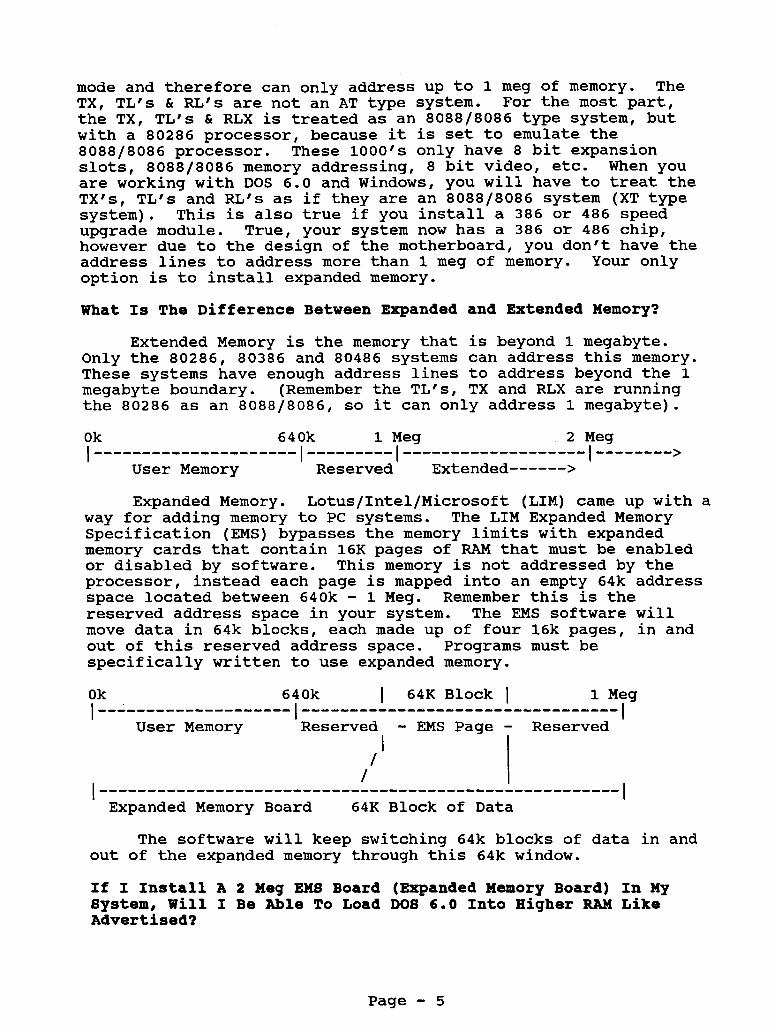
Expanded Memory. Lotus/Intel/Microsoft (LIM) came up with a way for adding memory to PC systems. The LIM Expanded Memory Specification (EMS) bypasses the memory limits with expanded memory cards that contain 16K pages of RAM that must be enabled or disabled by software. This memory is not addressed by the processor, instead each page is mapped into an empty 64k address space located between 640k - 1 Meg. Remember this is the reserved address space in your system. The EMS software will move data in 64k blocks, each made up of four 16k pages, in and out of this reserved address space. Programs must be specifically written to use expanded memory.
Ok 640k I 64X Block I 1 Meg I I-------------------- ................................. I
Reserved - EMS Page - Reserved User Memory I I
/ I
The software will keep switching 64k blocks of data in and out of the expanded memory through this 64k window.
If I Install A 2 Meg EM8 Board (Expanded Memory Board) In My System, Will I Be Able To Load DO8 6.0 Into Higher RAM Like Advertised?
Page - 5

No, to load DOS into higher memory you have to have EXTENDED
If you have Memory, not Expanded. Since none of the 1000's (except the 1000RSX) support Extended Memory this can't be done. a 2500, 3000, or 4000 series computer, you can load DOS in high memory, if you have enough. lOOORLX computer, see the section on the RLX for a way to load DOS high on your system.
For those of you who have the
There is an expanded memory board called the Invisible EMS Board that will allow you to load device drivers and TSR programs up high, even on the lOOO's! This board comes with all the software to enable it to load high, even with other DOS versions. You cannot load the command.com file up high, because that requires extended memory. can even free up more memory to load programs high.
If you use QRAM with this board you
If you have the Micro Mainframe EMS board, you will need the Although this board does 4.0 driver to work properly with DOS 6.
NOT let you load any programs high, you can still use this board with some of the DOS 6 programs.
Page - 6

Orisinal DO8 Version Chart
DOS Version DOS In ROM Computer Catalog Number
1000 lOOOA lOOOHD
25-1000 25-1000A 25-1001
2.11 2.11 2.11
lOOOEX lOOOHX
25-1050 25-1053
2.11 2.11 X
lO0ORL 1000RL-HD
25-1450 25-1451
3.30 3.30
X X
lOOORL4X 1000RLx 1000RLX-HD 1000RLX-HD
25-1452 25-1452B 25-1453 25-1453B
3.30 5.00 3.30 5.00
X X X X
lOOORSX 1000RSX-HD
25-1455 25-1454
5.00 5.00
X X
lO0OSL 1000SL/2
25-1401 25-1402
3.30 3.30
X X
lO0OSX lO0OSX lO0OSX
25-1051 25-1052 25-1054
3.20 3.20 3.20
lOOOTL 1000TL/2 1000TL/3
25-1601 25-1602 25-1603
3.30 3.30 3.30
X X X
lOOOTX 25-1600 3.20
NOTE: This chart just shows which version DOS the computer was shipped with from the factory. You can, however, run a higher version of DOS on your system. We have run all versions up to DOS 6.0 on all of the above computers.
If your system has the DOS in ROM, as indicated above, you will need to disable the ROMs by running the setup program for that computer. For more information see the section under your specific computer.
Page - 7

BIOS ROM Chart
Computer Catalog Number BIOS Ver Notes
1000 25-1000 01.00.00 01.01.00
lOOOA lOOOHD
2 5-1000A 25-1001
01.01.00 01.01.00
lOOOEX lOOOHX
25-1050 25-1053
01.02.00 02.00.00
1oooRL 25-1450 02 .oo. 00 02.00.01 02.00.00 02.00.01
1000RL-HD 25-1451
1oooRLx lO0ORLX 10 0 ORLX-HD 1000RLX-HD
25-1452 25-1452B 25-1453 25-1453B
02.00.00 02.00.00 02.00.00 02.00.00
lOOORSX 1000RSX-HD
25-1455 25-1454
01.10.00 01.10.00
lO0OSL 10OOSL/2
25-1401 25-1402
See Text 01.04.04
lO0OSX lO0OSX 1ooosx
25-1051 25-1052 25-1054
01.02.00 01.02.00 01.02.00
lOOOTL 1000TL/ 2 1000TL/3
25-1601 25-1602 25-1603
See Text 02.00.00 02.00.00
lOOOTX 25-1600 01.03.00
Page - 8

BIOS ROM Information
The information on the BIOS ROMs is as accurate as we have been able to obtain. It is not necessary for you to run out and upgrade your BIOS unless you're having trouble with your system and a BIOS upgrade will fix it. We have received many calls from customers that want to run high density drives in their 1000's and they think or have been told that you need to upgrade the BIOS in order to run high density drives. case. The BIOS on the 1000's is not what is stopping you from running high density drives. density controller built-in to the motherboard. For more information on running high density drives, check out the section on high density drives on the "Secrets Of The lOOO's, Vol 1" video tape. It will show you how to install and use high density drives in your 1000. Also check in this book under "Standard Drives and Drive Bay Chart".
That's simply not the
Most of the 1000's have only a low
1000, 1000An lOOOHD
Version Comments 01.00.00 Original BIOS ROM for 1000 (25-1000)
01.01.00 Original BIOS ROM for lOOOA and 1000HD. This version is
also the upgrade version for the 1000 (25-1000) listed above
The 01.01.00 corrects an extended write cycle that can cause some hard drive controllers to fail. The new version also corrects long printer strobe signals. If you have one of our newer IDE controllers, we have programmed our ROM on the controller card to work around the extended write cycle with the 01.00.00 ROM. This way you don't need to upgrade to the newer ROMs.
NOTE: There are two versions of the 01.00.00 ROM, a single chip version and a dual chip version. If you have the single chip version, simply replace the 01.00.00 ROM with the newer 01.01.00 ROM. If you have the two chip version, you will also need to upgrade the PAL chip.
Part Number Version Chip Socket MXP-0081 01.01.00 u9
100OEX
Version Comments 01.02.00 Latest version ROM. Same ROM that is used in the
lOOOSX computer.
Page - 9

There are two revisions of the lOOOEX motherboard. Both use the same B I O S ROM, however, the ROM socket locations are different.
Part Number Version Chip Socket MXP-0005 01.02.00 U17 First Revision MXP-0 0 0 5 01.02.00 u4 4 Revision D motherboard
lOOOHX
Version Comments 02.00.00 Latest version
Part Number Version Chip Socket MXP-0493 02 .oo. 00 u12
lOOORL L 1000RL-ED
Version Comments 02.00.00 Original version 02.00.01 Corrects mouse port problem
If your Deskmate randomly locks up when using the PS/2 style mouse with the RL or RL-HD, then change the ROM to the 02.00.01 version. There is a compatibility problem between the mouse driver in the ROM and Deskmate. The new ROM has a revised mouse driver . Part Number Version Chip Socket MXP- 0 8 10 02.00.01 U3 0
lOOORLX (25-1452) L 1000RLX-HD (25-1453)
Version Comments 02.00.00 Original version
Part Number Version Chip Socket MXP-0890 02.00.00 U3 2
lOOORLX (25-l452B) C 1000RLX-HD (25-1453B)
Version Comments 02.00.00 Original version
Part Number Version Chip Socket MXP-0953 02.00.00 U13
Page - 10

1000RSX
Version Comments 01.10.00 Original Version ROM
Part Number Version Chip Socket 01.10.00 U18
1OOOSL
Version Comments 01.04.00 First ROM release. Sharp ROM Chips version 1, type 32 01.04.00 Second ROM release. Sharp ROM 2, type 33 or is a
01.04.01 Sharp ROM 4, type 41 01.04.02 Sharp ROM 6, type 47 02.00.01
Hitachi ROM 2, type 33
Announced version that contains Deskmate 3.5 may not be available. Noted here for informational purposes.
In the lOOOSL there were three different manufacturers BIOS types that were used. They were Tandy, Sharp and Hitachi. To determine which BIOS manufacturer you have, drive letter and at the prompt type:
switch to the ROM's
TYPE V <enter>
It will respond back with a number. to see which ROM you have.
Look at the following chart
32 Sharp 1 33 Sharp 2 33 Hitachi 2
41 Sharp 4 47 Sharp 6 79 Tandy
The SL motherboard uses two ROM chips. marked with an SU for Sharp or HU for Hitachi. Hitachi ROM in an SU socket and DO NOT use a Sharp ROM in a HU socket. Due to the many variations of the ROMS in the lOOOSL, we do not advise that you attempt to upgrade the ROMS solely for having the latest version.
It' was announced that Deskmate 3.5 would be available for the SL in a ROM upgrade.
Part Number Version Chip Socket MXP-0694 01.04.02 su2 Odd Chip, Sharp 6 MXP-0695 01.04.02 su1 Even Chip, Sharp 6
The sockets will be DO NOT use a
We have not seen this available yet.
MXP-0604 01.04.00 HU2 Odd Chip, Hitachi MXP - 0 6 0 6 01.04.00 HU1 Even Chip, Hitachi
70B-1360 02.00.01 Deskmate 3.5 in ROM, may not be available yet.
Page - 11

Version Comments 01.04.04 Original ROM 02.00.01 Announced version that contains Deskmate 3.5 may not
be available. Noted here for informational purposes.
It was announced that Deskmate 3.5 would be available for the SL in a ROM upgrade.
Part Number Version Chip Socket MXP-0202 01.04.04 su3 Sharp ROM, Even MXP-0203 01.04.04 su4 Sharp ROM, Odd 70C-1360 02.00.01 May not be available yet.
lO0OSX
Version Comments 01.02.00 Original and current version
This is the same ROM that it used in the lOOOEX
Part Number Version Chip Socket MXP-0 0 0 5 01.02.00 U4 1
lOOOTL
Version Comments 01.04.00 Original ROM, referred to as Sharp 1 or Sharp 2, type 32 01.04.01 Sharp ROM 4, type 41 01.04.02 Sharp ROM 6, type 47 02.00.01 Announced version that contains Deskmate 3.5 may not
be available. Noted here for informational purposes.
Like the lOOOSL, in the lOOOTL there were three different manufacturers BIOS types that were used. They were Tandy, Sharp and Hitachi. switch to the ROM's drive letter and at the prompt type:
To determine which BIOS manufacturer you have,
TYPE V <enter>
It will respond back with a number. to see which ROM you have.
Look at the following chart
32 Sharp 1 32 Sharp 2
41 Sharp 4 47 Sharp 6 79 Tandy
It was announced that Deskmate 3.5 would be available for the SL in a ROM upgrade. We have not seen this available yet.
Page - 12

Part Number Version Chip Socket MXP-0695 01.04.02 u55 Even ROM MXP-0694 01.04.02 u57 Odd ROM 7 OB-13 60 02.00.01 May not be available yet.
10 0 OTLl2
Version Comments 02.00.00 Original ROM 02.00.01 Announced version that contains Deskmate 3.5 may not
be available. Noted here for -informational purposes.
It was announced that Deskmate 3.5 would be available for the SL in a ROM upgrade.
Part Number Version Chip Socket MXP-0731 02.00.00 u4 5 7 OA- 13 6 0 02.00.01 May not be available yet.
100 OTL/ 3
Version Comments 02.00.00 Current version of the ROM
Part Number Version Chip Socket MXP-0854 02.00.00 U3 1
1000TX
Version Comments 01.03.00 Original Version - Current The TX BIOS ROM is made up of two chips. other is marked even. Each chip has its own part number.
One is marked odd the
Part Number Version Chip Socket MXP-0494 01.03.00 U3 8 Even Chip MXP-0516 01.03.00 u3 9 Odd Chip
Page - 13

CPU Speed an8 Power Supply S i z e Chart
CPU Speed Mhz Power Supply Computer Catalog Number High/Low Watts
1000 25-1000 4.77 lOOOA 25-1000A 4.77 lOOOHD 25-1001 4.77
lOOOEX 25-1050 7.16 / 4.77 lOOOHX 25-1053 7.16 / 4.77
lO0ORL 25-1450 9.44 / 4.77 1000RL-HD 25-1451 9.44 / 4.77
lO0ORLX 25-1452 10 / 5 lO0ORLX 25-1452B 10 / 5 10 0 ORLX-HD 25-1453 10 / 5 1000RLX-HD 25-1453B 10 / 5
lOOORSX 25-1455 25 / 8 1000RSX-HD 25-1454 25 / 8
lO0OSL 25-1401 8 / 4.77 1000SL/2 25-1402 8 / 4.77
lO0OSX 25-1051 7.16 / 4.77 lO0OSX 25-1052 7.16 / 4.77 lO0OSX 25-1054 7.16 / 4.77
lOOOTL 25-1601 8 / 4.77 1000TL/2 25-1602 8 / 4.77 1000TL/3 25-1603 10 / 5
54 54 54
28 28
25 25
25 25 25 25
25 25
67 67
67 67 67
67 67 67
l O O O T X 25-1600 8 / 4.77 67
Note: There are ways to speed up most of the 1000's. See the section on speed upgrades.
Page - 14

Math Co-Processor Chart
Computer
1000 lOOOA lOOOHD
lOOOEX lOOOHX
lO0ORL 1000RL-HD lO0ORLX 1000RLX-HD
10 0 ORSX
lO0OSL 10 0 OSL/ 2
lO0OSX
lOOOTL 1000TL/2 1000TL/3
lOOOTX
Notes:
Math Co
N/A 8087 8087
N/A N/A
N/A N/A N/A N/A
80387SX
8087-2 8087-2
8087-2
80287 80287 80287
80287
Speed Chip Location
5 Mhz U2 9 5 Mhz U2 9
25 Mhz
8 Mhz 8 Mhz
8 Mhz
8 Mhz + 8 Mhz + 10 Mhz + 8 Mhz +
u10
u2 1 u2 1
u3 3
U60 u4 3 u9
U15
N/A = Not Available. Some 1000's do not have a math co-processor socket.
The 1000TL, TL/2, TL/3, and TX can use the 80287-XL math co-processor.
You can always use a faster speed math co-processor than what is called for, it will simply slow down to the CPU's speed.
It is also possible to use a slower speed math co-processor. What you will be doing is pushing the math co-processor. generally works as long as you are close to the CPU's speed. For example, a 8 Mhz 80827 will work in a 10 Mhz CPU.
This
Page - 15

Emansion Slot Chart
Computer Catalog Number
1000 lOOOA lOOOHD
lOOOEX lOOOHX
lO0ORL 100 ORL-HD
lO0ORLX lO0ORLX 1000RLX-HD 1000RLX-HD
lOOORSX 1000RSX-HD
lO0OSL 1000SL/2
lO0OSX lO0OSX lO0OSX
lOOOTL 10 0 OTL/ 2 1000TL/3
lOOOTX
25-1000 2 5-1000A 25-1001
25-1050 25-1053
25-1450 25-1451
25-1452 25-1452B 25-1453 25-1453B
25-1455 25-1454
25-1401 25-1402
25-1051 25-1052 25-1054
25-1601 25-1602 25-1603
25-1600
# of Expansion Slots Type 8/16
3 3 3
N/A N/A
1 1
1 1 1 1
2 2
5 5
5 5 5
5 4 4
5
8 8 8
8 8
8 8 8 8
16 16
8 8
8 8 8
8 8 8
8
N o t e s :
(1) The 1000 EX and HX has a 62 pin expansion connector that is on the motherboard. If you attach the memory board to this connector you will have an additional 1 or 2 slots depending on the manufacturer of the memory board. There are also companies that supply a slot adapter where you can install 8 bit XT style cards into the EX and HX. memory board installed first before using one of these adapters.
The expansion slots in all of the 1000's are only loaa long. The standard XT style expansion slots are 13Ia long. Be careful when purchasing expansion boards and hard disk cards. less than loaa long.
It is recommended that you have the
They have to be
Page - 16

Base Memorv P Total Memorv Chart
T h i s c h a r t shows the standard amount of memory t h a t each system came w i t h . It a l s o shows t h e maximum amount of memory tha t it can be expanded t o on the motherboard. It should be noted t h a t you can expand the memory beyond t h e maximum amount on t h e motherboard by adding spec ia l expanded memory boards t o the system. These boards w i l l plug i n t o one of t h e expansion s l o t s .
Computer Catalog Number Base Memory Total Memory
1000 lOOOA lOOOHD
lOOOEX lOOOHX
lO0ORL 1000RL-HD
lO0ORLX lO0ORLX 100 ORLX-HD 10 0 ORLX-HD
lOOORSX 1000RSX-HD
lO0OSL 10OOSL/2
lO0OSX lO0OSX lO0OSX
lOOOTL 1000TL/ 2 1000TL/3
lOOOTX
25-1000 25-1000A 25-1001
25-1050 25-1053
25-1450 25-1451
25-1452 25-1452B 25-1453 25-1453B
25-1455 25-1454
25-1401 25-1402
25-1051 25-1052 25-1054
25-1601 25-1602 25-1603
25-1600
128K 128K 128K
256K 256K
512K 512K
512K 512K 1 Meg 1 Meg
1 Meg 1 Meg
384K 512K
384K 384K 384K
640K 640K 640K
640K
640K 640K 640K
640K 640K
768K 768K
1 Meg 1 Meg 1 Meg 1 Meg
9 Meg 9 Meg
640K 640K
640K 640K 640K
76813 768K 768K
768K
Notes: See Next Page.
Page - 17

Notes:
(1) The 1000, lOOOA and lOOOHD are not expandable on the mother- board. They require a special memory board that has a DMA chip. these systems. For more information on these boards, check the section for the 1000.
A standard XT type memory board will not work in
(2) The lOOOEX and lOOOHX are not expandable on the motherboard. They require a special memory board that has the DMA chip on board. This is NOT the same memory board that the 1000, 1000A, lOOOHD uses. The EX and HX computer does not take expansion boards with card edge connectors, they use a 62 pin connector instead. For more information on this board, check the section for the lOOOEX and HX.
Page - 18

Speed Upqrade Chart
Computer Catalog Number
1000 lOOOA lOOOHD
25-1000 25-1000A 25-1001
lOOOEX 25-1050 1000HX 25-1053
lO0ORL 25-1450 100 ORL-HD 25-1451
lO0ORLX 25-1452 lO0ORLX 25-1452B 10 0 ORLX-HD 25-1453 1000RLX-HD 25-1453B
lOOORSX 25-1455 1000RSX-HD 25-1454
lO0OSL 25-1401 1000SL/2 25-1402
lO0OSX lO0OSX lO0OSX
25-1051 25-1052 25-1054
lOOOTL 25-1601 1000TL/2 25-1602 1000TL/3 25-1603
Type Of Upgrade
v-20 v-20 v-20
v-20 v-2 0
V-30 V-30
v-20 v-20 v-20
386 or 486 CPU Module 386 or 486 CPU Module
lOOOTX 25-1600 386 or 486 CPU Module
Some of the 1000's you can speed up the computers operation by replacing the CPU with a different type.
v20 - Replaces the 8088 CPU, 10 to 50% speed increase, does not change the clock speed. This is an optimized CPU chip.
V30 - Replaces the 8086 CPU, 10 to 50% speed increase, does not change the clock speed. This is an optimized CPU chip.
386/486 CPU Module - There is a 386 and 486 CPU module by Improve Technologies that will allow you to replace the 286 CPU in the above listed systems. The 386 CPU will double the clock speed from 8 to 16 Mhz. The 486 CPU module will also double the clock speed from 8 to 16 Mhz, plus the on-board cache will increase the speed another 50 to 100%.
Page - 19

The speed increase that you will see can vary from program
You may
to program. Once the programs are loaded into memory, they will execute faster. If your programs seem to take a long time to load from the hard disk, a speed upgrade may not help. need a hard drive with a faster data transfer rate. For more information on this, see the Hard Drive and Hard Card section.
There was a company named PC Technology that made a 286 upgrade board. out of business for quiet a while now. available on the used market.
This board was also sold by Tandy. The company has been This board is still
286 Express Board Part Number 25-1035 (Discontinued)
The 286 Express Board is an 286 card that was designed to work with the 1000, 1000A, lOOOHD and lOOOSX computers. The 286 Express board has been discontinued for quite awhile now, however, they have been showing up on the used market.
The 286 Express board kit required an expansion slot and contains a main expansion card, a daughter board and software to activate the board. installing a 80287. The board will work with either a 5MHz or 8MHz 80287. However, we recommend that you use the 8MHz version for best performance. The 286 Express board was sold with the daughter board for the 1000A, 1000HD, and lOOOSX computers. If you have one of the original Tandy lOOO's, (25-1000) you will need a different daughter board, part number AXX-7130. We have been informed that this special daughter board is no longer available. check to see which daughter board you're getting or which computer the express board came out of. the software you need to run the board.
There is also a math co-processor socket for
If you happened to pick up a used 286 Express board,
Also, make sure you get
We have found that some programs will not run correctly if For example, the smart clock chip the board is in the 286 mode.
software requires the 286 Express board to be put into the 8088 mode before you can read the clock chip. To change the mode of the express board, you would type:
PCT 88 <--- Puts the board in the 8088 mode PCT 286 <--- Puts the board in the 80286 mode
There is a 10 position dip switch found on the board. These switches set the clock speed for the math co-processor, the computer model and memory limits for caching. The switch settings are as follows:
sw1 sw2 SWlO Math Co-processor Setting ON OFF OFF 8MHz 80287 math co-processor installed OFF ON ON 5MHZ 80287 math co-processor installed OFF OFF OFF No math co-processor
Page - 20

sw3 Computer Model Setting
ON Board is installed in a lOOOSX OFF Board is installed in a 1000, lOOOA or lOOOHD
SW4 SW5 SW6 SW7
OFF OFF OFF OFF OFF OFF OFF OFF ON ON
OFF OFF OFF OFF ON ON ON ON OFF OFF
OFF OFF ON ON OFF OFF ON ON OFF OFF
OFF ON OFF ON OFF ON OFF ON OFF ON
Memory Limits For Caching, Use Default
64K 128K 192K 256k <- Default setting 320K 384K 448K 512K 576K 640K
SW8 Not Used
OFF <---- MUST be set to OFF
sw9 Boards 1/0 Address
ON Board uses 1/0 address 3EOh OFF Board uses 1/0 address l O O h
Page - 2 1

B u i l t In Video Chart
Built In Video Computer Catalog Number
1000 lOOOA lOOOHD
.25-1000 25-1000A 25-1001
CGA / Mono Composite CGA / Mono Composite CGA / Mono Composite
CGA / Mono Composite CGA / Mono Composite
lOOOEX lOOOHX
25-1050 25-1053
lO0ORL 1000RL-HD
CGA / Hercules Mono TTL CGA / Hercules Mono TTL
25-1450 25-1451
lO0ORLX lO0ORLX 1000RLX-HD 1000RLX-HD
25-1452 25-1452B 25-1453 25-1453B
VGA VGA VGA VGA
lOOORSX 1000RSX-HD
25-1455 25-1454
VGA 1024x768 VGA 1024x768
lO0OSL 1000SL/2
CGA / Hercules Mono TTL CGA / Hercules Mono TTL
25-1401 25-1402
lO0OSX lO0OSX lO0OSX
CGA / Mono Composite CGA / Mono Composite CGA / Mono Composite
25-1051 25-1052 25-1054
lOOOTL 10 OOTL/ 2 1000TL/3
25-1601 25-1602 25-1603
CGA / Mono TTL CGA / Mono TTL CGA / Mono TTL
lOOOTX CGA / Mono Composite 25-1600
NOTES
You can install VGA in all of the lOOO's, except the 1000, CGA in these systems cannot be lOOOA and 1000HD. The built-in
disabled.
The CGA that Tandy built into the lOOO's, is capable of displaying 16 colors, whereas standard CGA displays only 4 colors.
Page - 22

Monitor Chart
Model VM-1 VM-2 VM-3 VM-4 VM-5 VM-5 * CM-1 CM-2 CM-4 CM-5 CM-5 * CM-8 * CM-10 CM-11
EGM-1
VGM- 10 0 VGM-150 VGM-200 VGM-2 2 0 VGM-300 VGM- 3 4 0 VGM-390 VGM-4 4 0 VGM-4 4 1 VGM-4 5 0
Catalog # 26-5111 26-3211 25-3010 26-1020 25-3011 25-3012
26-5112 26-3212 25-1021 25-1023 25-1043 26-3512 25-1022 25-1024
25-4035
25-4040 25-4090 25-4041 25-4044 25-4042 25-4047 25-4091 ,
25-4046 25-4048 25-4049
* Monitor Notes: CM-5, Tandy produced
Type Resolution Dot Pitch Mono/TTL 720x384 Mono/Composite Mono/TTL 720x384 Mono/Composite 640x200 Mono/TTL 720x384 Mono/TTL 720x384
CGA 640x400 CGA 640x200 CGA 320x200 CGA 320x200 CGA 320x200 CGA/Analog 640x192 CGA 640x200 CGA 640x200
EGA 640x350
VGA / Mono 640x480 VGA/Mono Full Page VGA/Color 64 0x4 80 VGA/ Color 640x480 VGA/ Color 640x480 SVGA/Color 1024x768 SVGA/Color 1024x768 SVGA/Color 1024x768 SVGA/Color 1024x768 SVGA/Color 1024x768
.42
.52
.31
.39
.39
.28
.28
.28
2 models of the CM-5. The model 25-1023 was the first of the two models of the CM-5 monitors to be made.
VM-5, Tandy produced 2 models of the VM-5. The model 25-3011 was the first of the two models of the VM-5 monitors to be made.
CM-8 is a 13" analog monitor with a built-in speaker for the Color computers. 640x192 in graphics mode.
It will display up to 80x24 in text mode and
Page - 23

Standard F ~ O R R Y Drives & Number of Drive Bays Chart
Computer Catalog Number Standard Drives Drive Bays Number Of
1000 lOOOA lOOOHD
lOOOEX lOOOHX
lO0ORL 1000RL-HD
lO0ORLX lO0ORLX 1000RLX-HD 1000RLX-HD
lOOORSX 1000RSX-HD
lO0OSL 1000SL/2
lO0OSX lO0OSX lO0OSX
lOOOTL 1000TL/2 1000TL/3
lOOOTX
25-1000 2 5-10 0 OA 25-1001
25-1050 25-1053
25-1450 25-1451
25-1452 25-1452B 25-1453 25-1453B
25-1455 25-1454
25-1401 25-1402
25-1051 25-1052 25-1054
25-1601 25-1602 25-1603
25-1600
5.25 360K 5.25 360K 5.25 360K/10 Meg HD
5.25 360K 3.5 720K
3.5 720K 3.5 720K3/20 Meg HD
3.5 1.44Meg 3.5 1.44Meg 3.5 1.44Meg/40 Meg HD 3.5 1.44Meg/40 Meg HD
3.5 1.44Meg 3.5 1.44Meg/52 Meg HD
5.25 360K 3.5 720K
2 - 5.25 360K 1 - 5.25 360K 2 - 5.25 360K
3.5 720K 3.5 720K 3.5 720K (1)
3.5 720K
NOTES :
360K drives = low density 720K drives = low density
1.2 meg drives = high density 1.44 meg drives = high density
2 2 2
1 2
2 2
2 2 2 2
2 2
2 2
2 2 2
3 3 3
2
The TL/3 has a built-in hi-density floppy controller even though it only came with a low-density drive.
These units have 2 - 5.25" drive bays
These units have 2 - 3.5'l drive bays
This unit has one 3.5" drive bay and one 5.25" drive bay
Page - 24

(5) These units have 2 - 3.5" drive bays and one 5.2511 drive bay.
Hicrh Densitv Drive Information
If your system has a built-in high density controller, there is no problem with you using high density drives. only has a built-in low density controller, IT IS POSSIBLE to install a high density drive kit into your system.
If your system
Just read on.
Despite what you may have been told you CAN run a high density drive in your system even though your system may only have a low density controller! controller card, a high density drive and software. Please note that a standard high density controller card will not work.
You will need a special high density
"1 was told that I can't run high density drives in my system, but you are telling me I can1*
YES! There are many third party products (products not produced by Tandy themselves) that are available to you. One of these items is a high density disk drive kit. Even though you may have been told you can't do that, you really can! Sometimes sales people that do not supply third party products for your system will tell you it can't be done, especially if they don't sell it themselves!
W h y can't I just change my BIOS ROM to let me run high density drives"
The problem is not in the system's BIOS ROM, but with the built-in controller. data to and from the controller at the rate of 250K per second. rate of 500K per second.
You see a low density drive transfers
While the high density drive transfers data at the
Therefore, when you connect a high density drive up to the low density controller, the low density controller CANNOT transfer the data as fast as the high density drive is requiring it to. message.
You will then get a general failure error
With most high density controllers, you can transfer data at both rates of 250K and 500K, This way you can run either a low density drive or a high density drive from a high density controller.
Page - 25

Power In F~ODDV Drive Cable Chart
Power In Drives Using Power Computer Catalog Number Floppy Cable In The Floppy C a b l e
1000 lOOOA lOOOHD
lOOOEX lOOOHX
lO0ORL 1000RL-HD
lO0ORLX lO0ORLX 10 0 ORLX-HD 1000RLX-HD
lOOORSX 1000RSX-HD
lO0OSL 1000SL/2
lO0OSX lO0OSX lO0OSX
lOOOTL 1000TL/ 2 1000TL/3
lOOOTX
25-1000 25-1000A 25-1001
25-1050 25-1053
25-1450 25-1451
25-1452 25-1452B 25-1453 25-1453B
25-1455 25-1454
25-1401 25-1402
25-1051 25-1052 25-1054
25-1601 25-1602 25-1603
25-1600
Y e s
Y e s Y e s
Y e s Y e s Y e s Y e s
Y e s Y e s
Y e s
Both 3.5" dr ives
3.5" floppy dr ives 3.5" floppy dr ives
3.5" floppy dr ives 3.5" floppy dr ives 3.5" floppy dr ives 3.5It floppy dr ives
3.5" floppy dr ives 3.5" floppy dr ives
Only 3.5" dr ive A:
Y e s Only 3.5" f loppies Y e s Only 3.5" f loppies Y e s Only 3.511 f loppies
Y e s Only 3.5" dr ive A:
Notes: See Next Page.
Page - 26

Notes:
On the systems where the power to the 3.5" floppy drive is supplied through the flat ribbon cable, you will need a special floppy drive that has been designed to pull the power through the flat ribbon cable. drive in one of these systems, you will not only damage the floppy drive but also damage the motherboard,
If you try to use a standard 3.5Il floppy
In all other systems where power DOES NOT come through the flat ribbon cable most standard floppy drives will work. You may, however, need a longer floppy drive cable for a proper fit.
TECH TIP:
If you are installing a 3.5'l floppy drive into your system, did you know that you can install a 1.44 meg floppy drive and have it work as a 720K floppy? You can! It works perfectly! When you buy a 720K floppy drive, see if you can get a 1.44 floppy drive, this way if you ever upgrade to a new system, you can pull out the 3 .5" floppy drive and install it into a new system and it will work as a 1.44 drive! We recommend TEAC floppy drives, as we have had the best success with this brand.
Page - 27

Built-In F~OD D V Controller C IDE Interface Chart
Computer Catalog Number Floppy Controller IDE Interface
1000 lOOOA lOOOHD
25-1000 25-1000A 25-1001
1000EX 25-1050 lOOOHX 25-1053
lO0ORL 25-1450 1000RL-HD 25-1451
lO0ORLX 25-1452 lO0ORLX 25-1452B 100 ORLX-HD 25-1453 1000RLX-HD 25-1453B
lOOORSX 25-1455 1000RSX-HD 25-1454
lO0OSL 25-1401 1000SL/2 25-1402
lO0OSX 25-1051 lO0OSX 25-1052 lO0OSX 25-1054
lOOOTL 25-1601 1000TL/ 2 25-1602 1000TL/3 25-1603
Low Low Low
Low Low
Low Low
High High High High
High High
Low Low
Low Low Low
Low Low High (1)
XT XT
XT XT XT XT
AT AT
XT XT
lOOOTX 25-1600 Low
Notes: Despite what you may have been told, you CAN run a high density drive in your system even though your system may only have a low density controller! controller card, a high density drive and software. Please note that a standard high density controller card will not work.
You will need a special high density
(1) The TL/3 has a built-in high density controller, however the computer came from the factory with only a low density drive installed.
Low - This means the system only has a low density controller built-in. This low density controller will only control 360K or 720K capacity drives.
High - This means the system has a high density controller built in. This controller will support 360K, 720K, 1.2 Meg and 1.44 Meg floppy drives without an additional controller.
Page - 28

XT - These systems have an XT IDE hard disk interface. AT - These systems have an AT IDE hard disk interface. Note: Even though the XT and AT hard disk interface may physically look the same, they are not electrically the same. DO NOT connect an AT interface drive to the XT interface and like wise DO NOT connect an XT interface drive to an AT interface.
High Density Drive Information If your system has a built-in high density controller, there is no problem with you using high density drives. only has a built-in low density controller, IT IS POSSIBLE to install a high density drive kit into your system.
Despite what you may have been told you CAN run a high density drive in your system even though your system may only have a low density controller! controller card, a high density drive and software. Please note that a standard high density controller card will not work.
If your system
Just read on.
You will need a special high density
"1 was told that I can't run high density drives in my system, but you are telling me I can"
YES! There are many third party products (products not produced by Tandy themselves) that are available to you. One of these items is a high density disk drive kit. Even though you may have been told you can't do that, you really can! Sometimes sales people that do not supply third party products for your system will tell you it can't be done, especially if they don't sell it themselves!
W h y can't I just change my BIOS ROM to let me run high density drives"
The problem is not in the system's BIOS ROM, but with the built-in controller. data to and from the controller at the rate of 250K per second. rate of 500K per second.
You see a low density drive transfers
While the high density drive transfers data at the
Therefore, when you connect a high density drive up to the low density controller, the low density controller CANNOT transfer the data as fast as the high density drive is requiring it to. message.
You will then get a general failure error
With most high density controllers, you can transfer data at both rates of 250K and 500K, This way you can run either a low density drive or a high density drive from a high density controller.
Page - 29

Serial/Parallel/Other Ports Chart
Computer Catalog Number
1000 lOOOA lOOOHD
1000EX lOOOHX
lO0ORL 100 ORL-HD
lO0ORLX lO0ORLX 1000RLX-HD 1000RLX-HD
lOOORSX 1000RSX-HD
lO0OSL 10 OOSL/ 2
lO0OSX lO0OSX lO0OSX
lOOOTL 1000TL/ 2 1000TL/3
lOOOTX
NOTES:
DB-9
DB-25
The
25-1000 2 5-10 OOA 25-1001
25-1050 25-1053
25-1450 25-1451
25-1452 25-1452B 25-1453 25-1453B
25-1455 25-1454
25-1401 25-1402
25-1051 25-1052 25-1054
25-1601 25-1602 25-1603
25-1600
systems marked
Serial
DB-9 DB-9
DB-9 DB-9 DB-9 DB-9
DB-9 DB-9
DB-9 DB-9
DB-9 DB-9 DB-9
DB-9
with a
Printer
Card Edge Card Edge Card Edge
Card Edge Card Edge
DB-25 DB-25
DB-25 DB-2 5 DB-25 DB-25
DB-25 DB-25
Card Edge Card Edge
Card Edge Card Edge Card Edge
Card Edge Card Edge Card Edge
Card Edge
Other
Light Pen/Joystick Light Pen/Joystick Light Pen/Joystick
Joystick Joystick
PS2 PS2
PS2 PS2 PS2 PS2
PS2 PS2
Mouse/Joystick Mouse/Joystick
Mouse/Joystick Mouse/Joystick Mouse/Joystick Mouse/Joystick
Mouse Mouse
Joystick Joystick
Light Pen/Joystick Light Pen/Joystick Light Pen/Joystick
Joystick Joystick Joystick
Joystick
DB-9 under the serial port means that it has a 9 pin serial port built-in to the system.
The systems marked with a DB-25 under the printer port means that it has an IBM style 25 pin printer port connection.
Card Edge The systems marked with Card Edge under the printer port means that these systems use a 34 pin card edge connector as the printer port connection. This is not a standard way of connecting a printer to a computer, however, Tandy used this method for several years.
Light Pen Some of the earlier 1000's had a light pen port. This should not be confused with a serial port, even though
Page - 30

it may look like one. There was a company that had made a light pen for the lOOO's, however, we don't recall seeing it available on the market for any length of time.
Joystick The systems that are marked with a joystick port use a Tandy style joystick. These are not standard type joysticks and they connect to the system with a 6 pin DIN plug. A standard joystick uses a 15 pin DB-15 style plug.
PS2 Mouse Some of the latter 1000's came equipped with a PS/2 style mouse port. This mouse port requires a PS/2 mouse not a serial mouse. We have noted that some software will not work with the PS/2 mouse on these systems, even though the software has the PS/2 style mouse as an option. We have noted also that not all manufacturers PS/2 mice are compatible with the 1000's PS/2 mouse port.
Page - 31

Systems With Srmcial 8etuD Proarams
Computer Catalog Number Setup Program File Name
1000 lOOOA lOOOHD
lOOOEX lOOOHX
lO0ORL 1000RL-HD
1oooRLx lO0ORLX 1000RLX-HD 1000RLX-HD
lOOORSX 1000RSX-HD
lO0OSL 1000SL/2
lO0OSX lO0OSX lO0OSX
lOOOTL 1000TL/2 1000TL/3
lOOOTX
NOTES:
25-1000 2 5-1000A 25-1001
25-1050 25-1053
25-1450 25-1451
25-1452 25-1452B 25-1453 25-1453B
25-1455 25-1454
25-1401 25-1402
25-1051 25-1052 25-1054
25-1601 25-1602 25-1603
25-1600
SETUPHX
SETUPRL SETUPRL
SETUPRLX SETUPRLX SETUPRLX SETUPRLX
SETUPRSX SETUPRSX
SETUPSL SETUPSL2
SETUPTL SETUPTL2 SETUPTL3
Not al, of the 1000's have a setup program. Th,s setup program is used to configure the system for floppy drives, color or mono monitor, primary boot device ROM or disk, etc.
For the systems that don't have the setup program, when your system boots, it looks to see what kind of floppy drives you have and what kind of monitor.
It should be noted that in all of the 1000's (EXCEPT the 1000RSX) you do not need to run setup when installing the hard drive or hard card. The system will look f o r one and use the BIOS ROM on the hard drive or hard card controller to configure itself during bootup.
Page - 32

Clock Chip Installation Chart
Computer Catalog Number Socket Location Clock Software
1000 lOOOA lOOOHD
25-1000 25-1000A 25-1001
u-10 U-51 u-10
or U-51
lOOOEX lOOOHX
25-1050 25-1053
u-44 u-12
lO0ORL 10 0 ORL-HD
25-1450 25-1451
U-28 Built In
lO0ORLX lO0ORLX 1000RLX-HD 10 0 ORLX-HD
Built In Built In Built In Built In
25-1452 25-1452B 25-1453 25-1453B
Built In Built In
lOOORSX 1000RSX-HD
25-1455 25-1454
lO0OSL 1000SL/2
25-1401 25-1402
U-13 U-13
(3) (3)
lO0OSX lO0OSX lO0OSX
25-1051 25-1052 25-1054
U-41 U-4 1 U-41
lOOOTL 1000TL/2 1000TL/3
25-1601 25-1602 25-1603
Built In Built In Built In
lOOOTX 25-1600 u-39 (4)
Notes:
If you have a hard card in your system and are having trouble getting the hard card to work once you have installed the clock chip, make sure that the hard card is fully seated back into the expansion slot. TX. The clock chip sits up high enough that it prevents the hard card from being properly seated back into the expansion slot. You may want to move the hard card to another slot, providing you have another one free.
This problem is most common with the
There is an alternative way to install a clock chip into your computer if you have a hard drive or hard card. You can install the clock chip under the ROM chip on the controller card the same way you would on the motherboard. controller card for a ROM chip that has the same number of pins
Simply check the
Page - 33

that the clock chip has. Also make sure that ROM chip is in a socket and not soldered onto the controller card.
If you are using the Delkin Devices clock chip, the most poplar clock chip out there, then follow these instructions on using the software. If you are using another brand clock chip, follow the instructions that came with that clock chip.
Use the DDCLOCK and DDINIT software that came with the clock chip for setting the date/time and recalling the date/time. See below on how to use the DDCLOCK and DDINIT.
On the lOOOFU and 1000RL-HD, simply install the clock then just set the date and time by using the DATE command and TIME command from the DOS prompt. With the clock installed, the system will automatically detect it and when you issue the DATE and TIME command it will automatically set the date and time in the clock chip.
On the lOOOSL and 1000SL/2, DO NOT use the DDCLOCK and DDINIT software that came with the clock chip. Instead use the SLCLK.COM program found on your original DOS disks. See below on how to use the SLCLK program.
On the lOOOTX if you are having problems using the DDCLOCK and DDINIT, then use the SMWCLOCK program that came on your original DOS disk. See below on how to use the SMWCLOCK program.
Page - 34

Usina the C l o c k Boftware
DDCLOCX and DDINIT
After you have installed the clock chip, follow these steps for installing the software.
1. Copy the DDCLOCK and DDINIT programs to your hard disk or your boot floppy disk.
2. Add the command DDCLOCK to your autoexec.bat file on your hard disk or boot floppy disk.
3. Next, at the DOS prompt type in: TIME to set the time then: DATE to set the date.
4. Now you have to initialize the clock chip. At the DOS prompt type in:
DDINIT <enter> DDINIT <enter>
You MUST run the DDINIT twice! The first time you run DDINIT it may display a strange date and time. When you run it the second time it should display the proper date and time.
NOTE: If you have a 286 Express Board installed in your 1000, you will need to add the following lines to your autoexec.bat file:
PCT 88 <- turn off the 286 express board DDCLOCK <- read the clock chip for the date & time PCT 286 <- turn the 286 express board back on
Only add the PCT 88 and PCT 286 lines to your autoexec.bat file only if you have the PCT 286 express board.
SLCLX Software (1OOOSL and 1 0 0 0 S L / 2 )
After you have installed the clock chip, follow these steps for installing the software.
1. Copy the SLCLK program to your hard disk or your boot floppy disk.
2. Add the command SLCLK S to your autoexec.bat file on your hard disk or boot floppy disk.
Page - 35

3. Next, at the DOS prompt type in: SLCLK S next: TIME to set the time then: DATE to set the date.
4. Now initialize the clock chip. At the DOS prompt type in:
SLCLK c <enter>
Reboot the computer and the correct date and time should be displayed.
SMWCGOCK Software (1000TX)
After you have installed the clock chip, follow these steps for installing the software.
1. Copy the SMWCLOCK program to your hard disk or your boot floppy disk.
2. Add the command SMWCLOCK S to your autoexec.bat file on your hard disk or boot floppy disk.
3. Next, at the DOS prompt type in: SMWCLOCK S next: TIME to set the time then: DATE to set the date.
4. Now initialize the clock chip. At the DOS prompt type in:
SMWCLOCK C <enter>
Reboot the computer and the correct date and time should be displayed.
Page - 36

Tandv 1000 InterruDts
A hardware interrupt is a signal that is sent to the microprocessor signaling that a device needs attention. Some interrupts are shareable with other devices, it is then possible to have two devices using interrupt 5 or IRQ 5. IRQ is the abbreviation for interrupt.
Depending on which computer you have, you may find that some boards or mice will NOT share an interrupt line with another device. For example, COM 1 and COM 3 both use IRQ 4. If you have a mouse on COM 1 and tried to install a modem on COM 3, the modem would not function properly due to an interrupt conflict. They are both trying to use IRQ 4. Most mouse software will not allow another device to use the same IRQ that the mouse is on.
On the original 1000, lOOOA and 1000HD, we have found that most interrupts are NOT shareable. Therefore, you will need to be extra careful when installing cards into these systems. For example, when we install a high density floppy controller into one of these three models, we have to use IRQ 3 or IRQ 4, depending on which one is not being used, as it will not share IRQ 6 where we normally assign it.
The rest of the 1000's seem to share interrupts without too much problem. You will still have the same interrupt problem when it comes to mice and modems. However, you can run a second printer port on IRQ5 with the hard drive sharing that same interrupt or install the high density controller into the system sharing IRQ 6.
It should also be noted that on the original 1000, 1000A, and 1000HD, that the video and hard drive interrupts are reversed from the way that they are normally found in a PC computer. Tandy modeled the interrupts after the IBM PC Jr. It wasn't until the SX and TX came out that Tandy then would give you the option of setting the computer in the PC Jr mode or a standard XT mode, as far as the interrupts where concerned. Most people didn't know that they could set the lOOOSX or TX into the standard XT mode. If you have ever bought one of our hard drives or hard cards, you were instructed to turn switch #2 on the motherboard opposite of the other three DIP switches. What we were having you do is set you computer into the standard XT mode, as far as the interrupts were concerned.
When the computer is in the PC Jr mode, the video and hard disk interrupts are reversed as shown below:
1000, 1000A, 1000HD, PC Jr IRQ 2 = Hard Drive IRQ 5 = Video
Page - 37

The standard XT mode is as follows:
IRQ 2 = Video IRQ 5 - Hard Drive We want to point out that some OLDER software, mainly games,
for the original 1000, would only work if the video interrupt was IRQ 5. These games have long been discontinued or updated so this should not be a concern anymore. However, if you still have some of this old software they may not work on the newer systems.
Hard drive controllers for the original 1000, lOOOA and 1000HD, need to be modified so the hard drive interrupt will be in IRQ 2. These modifications can be anything from moving some jumpers on the card, to cutting traces and soldering. of the modification will depend on the brand of the controller and model/revision of the card. Vol 2" manual for details'on how to modify the controllers.
The extent
Check the "Tech Notes & Jumpers
Some video boards, when installed into the lOOO's, (except 1000, lOOOA and 1000HD) may need the DIP switch #2 changed as if you were installing a hard drive into the system.
110 Addresses
Each device you add into one of the expansion slots requires an 1/0 address or you will have an address conflict. An easy way to explain 1/0 addresses is to think of your expansion slots (also called the expansion bus) as the street that you live on. Think of each device as a house on your street and each house has its own house number or street address. Imagine the problem the mailman would have delivering mail if two or more houses would have the same house number. problem if two boards were using the same address. each expansion card you install must have its own address.
The computer would have the same This is why
Remember the section on interrupts? We stated that two devices can share the same interrupt, that is because each device using that interrupt will have its own address. be careful when sharing interrupts.
But remember to
Serial and Parallel Port Addresses
Serial Ports COM 1 COM 2 COM 3 COM 4
Port Address 03F8 02F8 03E8 02E8
Page - 38

Parallel Port LPT 1 LPT 2 LPT 3
Port Address 03BC 0378 0278
Tandv 1000, 1000A, lOOOHD Hardware Interrupts
IRQ 0 IRQ 1 IRQ 2 IRQ 3 IRQ 4 IRQ 5 IRQ 6 IRQ 7
System Keyboard Note: Interrupts (IRQ's) are Hard Drive not shareable on the COM 2 early 1000, lOOOA and COM 1 lOOOHD with most other Video Vertical Sync expansion cards. If an Floppy Drives IRQ is free, then you Printer LPT 1 can use it.
All Other 1000's
IRQ 0 IRQ 1 IRQ 2 IRQ 3 IRQ 4 IRQ 5 IRQ 6 IRQ 7
System Keyboard Video Vertical Sync COM 2 / COM 4 COM 1 / COM 3 Hard Drive / Printer LPT 2 Floppy Drives Printer LPT 1
lOOORSX and 1000RSX-HD
IRQ 0 System IRQ 1 Keyboard IRQ 2 Route to interrupts 8 to 15 IRQ 3 COM 2 / COM 4 IRQ 4 COM 1 / COM 3 IRQ 5 Printer LPT 2 IRQ 6 Floppy 'Drives IRQ 7 Printer LPT 1
IRQ 8 IRQ 9 IRQ 10 IRQ 11 IRQ 12 IRQ 13 IRQ 14 IRQ 15
Real Time Clock Reserved Available Available Available Math Co-processor Hard Drive Controller 2nd Hard Drive Controller
Page - 39

Hard Drives and Hard Disk Cards
What is the difference between a hard drive and hard card for the lOOO's? Nothing really. into the system. controller card, the same two main components that is used for installing a hard drive. They are just mounted together on a special bracket so they plug into one of the expansion slots. The hard drive on the other hand, will require the use of a drive bay and the controller card will use an expansion slot. On some of the 1000's you only have 2 drive bays and if you have two floppy drives installed, this will mean you will have to give up one of your floppy drives. We recommend the hard cards, to save your drive bay. If you have a 3.5" hard drive in your system now and you want to turn it into a hard card, give us a call, we have hard card brackets available, along with an instructional video showing you how to assemble it.
It's just how they are mounted The hard cards are made up of a hard disk and
It is really very easy to do.
In some systems, such as the RL, RLX and RSX you must use a hard drive. There is not enough room to install a hard card.
Most people think that the speed of the hard drive or hard Companies are selling you card lies only with the access time.
on how fast the access time is on the hard drive or hard card. What is more important than the access time is the data transfer rate.
For those of you who are not sure what the access time or data transfer rate is, let us explain it this way. Let's say it takes you 15 seconds to walk to your mail box from the front door. That is your access time. Now it takes you 10 minutes to read the mail. That is your data transfer rate. With a hard drive, the access time is how long it takes the head in the hard drive to move to the location on the disk. The data transfer rate is how fast it can read the data.
You can have a hard disk with a slow 40ms access time, but a fast 500,000 bytes per second transfer, that out performs fast 12ms access time, but a slow 100,000 bytes per second data transfer rate.
What you want is a hard drive system or hard card with a fast access time, 28ms or faster (the lower the number, the faster the drive) and a high data transfer rate (above 400,000 bytes per second.
If you are using an older MFM or RLL drive, you are slowing your system down. bytes per second data transfer rate. called SpinRite, that will optimize the data transfer rate, but top data transfer rate will be about 170,000.
These hard drives only had a 30,000 to 170,000 You can buy a program
Page - 40

The newer IDE hard drives or hard cards, have a 400,000 to The next time you 500,000 bytes per second data transfer rate.
are using your system, watch to see how long it takes to load that program or data file. Think how much faster it could be with a high transfer rate,
L a r a e r H a r d D r i v e s and H a r d C a r d s
Despite what you may have been told, you can run any size hard drive in your system. You are not limited to the 20 or 40 meg that Tandy sold. Also, don't worry, your power supply will handle the larger hard drives and hard cards. Today the newer IDE hard drives and hard cards use less power than hard drive and hard cards made just a few years ago.
Hard Disk Cards must be under 9.5" in length in order to fit inside any of the 1000's. Make sure you buy your hard card from someone who makes them for the 1000's. Don't try to use just any hard card, it won't fit. They are generally 13" long.
The Seagate STllM (MFM controller) and STllR (RLL controller) can be used in most of the 1000's without modification. If you want to use this card in the original 1000, lOOOA or 1000HD, you have to modify the card. Watch I1Secrets of the lOOO's, Vol 2" to see the modification being done.
If you are installing this card in the lOOOTX or SX, you must change the DIP switch to enable IRQ 5 to be used for the hard drive. See the lOOOTX or SX section for more information on setting the switches.
The Western Digital WD1004 card can also be used in all of the lOOO's, except the lOOOSL and SL/2. The jumpers on the card must be set for a standard XT system. If you are installing this card in the 1000TX or SX, you must change the DIP switch to enable IRQ 5 to be used for the hard drive. See the lOOOTX or SX section for more information on setting the switches.
If this card is being used in a 1000, lOOOA or lOOOHD you must install a jumper onto position W27 to set the hard drive interrupt to IRQ 2,
The Western Digital WD1004 card can be used in the SL and SL/2 with a modification done to the card. capacitor to be soldered onto the back of the controller card. Watch '#Secrets of the lOOO's, Vol 2" to see the modification being done.
This requires a
The older Western Digital WD1002 controller can also be used in the 1000's. See the Tech Notes and Jumper Manual Vol 2 for exact jumper setting. This controller is becoming hard to find. Also this card, depending on the revision, may also need a solder modification and controller ROM change.
Page - 41

If you are planning on using one of the above mentioned controller cards in the original 1000, model 25-1000, you will need to upgrade the BIOS ROM to 0 1 . 0 1 . 0 0 . THIS ONLY APPLIES TO THE ORIGINAL 1000 , MODEL 25-lOOO!
IDE drives can be installed in all of the 1 0 0 0 ' s . You will need a Silicon Valley controller card, with a Tandy BIOS ROM. This controller card will work with most AT style IDE hard drives. This card is the most versatile controller we have found. If this controller card is being used in one of the 1 0 0 0 r s that have a built-in IDE port, you will need to put a jumper on position E2 of the controller card. For all other systems, no jumpers should be installed.
If you want to use this controller card to run a second hard drive, you will need to place a jumper on E2.
The IDE controller DOES NOT require you to update the BIOS ROM on the original 1000 , model 25-1000, like you do with the Seagate or Western Digital controllers.
The Seagate STOl SCSI controller could be used in all the lOOO's, except the TL3, RL, RLX, RSX, orignal 1000 , A and 1 0 0 0 H D . Most smaller SCSI drives have been discontinued for awhile.
NOTE: Some hard drive controllers will not work in the 1000 ' s . We recommend you stick with one of the above cards we have listed. on hard drive controllers. This volume is more on the systems themselves.
In volume 2, we will have complete jumper setting
For more information on hard drives, look under the section on your specific 1000 .
FloDDv Drives
Some of the floppy drives in the 1 0 0 0 ' s draw power through If you look under the IIPower In Floppy the floppy drive cable.
Drive Cable Chart" you will see which system and which drives do this. cable will need to be special drives or specially modified floppy drives. replacement or as an additional drive.
The drives that pull the power through the flat ribbon
DO NOT try to use a standard 3 . 5 " floppy drive as a
The 1000, A, SX and SL can all use a 3.5" 720K floppy drive. For more information on this, please see the section for your computer. NOTE: Some systems may require a longer floppy drive cable for an easier fit. floppy drive cable. will not run through the cable. 1 0 0 0 ' s Volume 2IV to see how to make this cable.
The SL will need a special, longer This cable has to be modified so the power
See the video llSecrets of the
Page - 4 2

Adding a 5 1/4" floppy drive can be done on most 1000's. The 1000EX, HX, RL, RLX and RSX will require an external floppy drive. All other systems will use a standard 360K floppy drive. NOTE: Some systems may require a longer floppy drive cable for an easier fit.
External.floppy drives can be added to most 1000's. The EX and HX models do require a special external floppy drive. Make sure if you are ordering an external drive for the EX or HX, that it is the proper one for your system.
An external floppy drive can be added to the other 1000's by adding a Micro Solutions Backpack drive. This floppy drive comes as a high density 1.2 meg or 1.44 meg unit. Connect to the this drive system's printer port. If your computer has a 34 pin card edge connector, simply add a second printer port card to your system and run the external floppy drive from this card.
If you have a lOOORL, RLX, RSX or TL/3, you can use the system's main printer port. for you computer and set the parallel port for Bi-Directional. NOTE: lOOORL owners, see the lOOORL section for a modification that will need to be done.
Make sure you run the setup program
Hiah Densitv Flo?mv Drives
Can't I just change my BIOS ROM to let me run high density drives? No. The problem is not in the system's BIOS ROM, but with the built-in controller. A low density drive transfers data to and from the controller at the rate of 250K per second. The high density drive transfers data at the rate of 500K per second.
Therefore, when you connect a high density drive up to the low density controller, the low density controller CANNOT transfer the data as fast as the high density drive is requiring it to. You will then get a general failure error message. The exception to this is with a 3.5" high density drive. This drive will simply act as a 720K floppy drive. NOTE: If you purchase a 1.44 meg floppy drive now and use it as a 720k floppy drive, later if you buy a new system, all you need to do is remove the 1.44 meg floppy drive from your 1000 and install it into your new computer, and then start using it as a 1.44 meg drive. For the last few years all of the 720K floppy drives that we have been sending out are really 1.44 meg. They work perfectly as a 720K.
This little trick with the high density drives ONLY works with the 1.44 meg drive and WILL NOT work with a 1.2 meg floppy.
Most high density controllers can transfer data at both rates of 250K and 500K. This way you can run either a low density drive or a high density drive from a high density controller.
Page - 43

The 1000TL/3, lOOORLX and lOOORSX support high density drives using the built-in controller. density drive and you're all set. NOTE: The TL/3 came with a 720K drive as A:, even though it can use high density drive.
All you need is a high
If you have any of the other 1000's you can still install a high density floppy drive into the 1000's. You will need a Micro Solutions Compaticard I1 and Compaticard software, a Teac high density floppy drive and a AT style floppy drive cable.
Connect the floppy drive cable to the Compaticard 11. Then set the jumpers on the card as follows:
J P 1 to position A JP2 to position A
Interrupt to 6 (if you have a 1000, A or HD use interrupt 3 or 4, whichever one is not being used by something in your system.)
Both DMA jumpers to 1
Install the Compaticard into one of the expansion slots.
The Teac 1.44 meg needs no modification.
The Teac 1.2 meg drive will need a jumper to be placed on the bottom of the drive on jumpers pins I. at the jumper pins, it may look like an H. drive to read/write both high and low density disk.
The Teac Dual Media Drive, is a floppy drive that has both a 1.44 meg and 1.2 meg drive built in to 1 - 5 1/4" drive unit. You will need to solder the two contacts together at position I on the bottom of the drive. This will allow the drive to read/write both high and low density disks.
Depending on how you look This will allow the
When connecting the flat ribbon cable to any of the above drives mentioned, you must use the last connector on the flat ribbon cable. This will be the connector with the twist in the cable right at the connector.
Copy the Compaticard software to your hard disk, hard card or boot floppy disk. config.sys file.
Then, add one of the following lines to your
DEVICE=CCDRIVER.SYS /12,7,3 DMAl IRQ6 <-- for 1.44 meg
DEVICE=CCDRIVER.SYS /12,3,3 DMAl IRQ6 <-- for 1.2 meg drive
DEVICE=CCDRIVER.SYS /12,3,3 /13,7,3 DMAl IRQ6 <-- dual media floppy drive
Page - 44

After you have added one of the above lines to the config.sys file, reboot your system and watch for a message about the Compaticard I1 loading a driver and assigning the high density drive a drive letter. It will become the last drive in the system.
NOTE: If you have the 1000, lOOOA or 1000HD, please change the IRQ6 in the above lines to whichever IRQ that you have the card set to.
Serial Ports and Modems
Modems come in two flavors, internal and external. If you are installing an external modem, you will need a serial port for the external modem to be connected to. You can check the Serial/Parallel Port Chart to see if your system came with a serial port built-in. If your system does not have a serial port and you want to use the external modem, you will need to add a serial port to your system. You may want to add a dual serial port board, this way if you ever want to connect a mouse to the system you will have the extra serial port available.
If you're installing an internal modem, then all you will need is a free expansion slot.
When installing a serial port or modem into your system, make sure that it does not conflict with another serial port that may in be your system. Each serial port or modem has to be set to a specific COM port, such as COMl or COM2. modem in your system, make sure you check to see which COM port it is assigned to before you install the serial board. the serial port to a different COM port setting.
If you have a
Then set
There are two main COM ports that can be installed into your system, COM 1 and COM 2. Each COM port is assigned to one of the system's interrupts.
COM 1 = IRQ 4 COM 2 = IRQ 3
COM 3 = IRQ 4 COM 4 = IRQ 3
As you can see from the above list of COM ports, it is possible to also have a COM 3 and COM 4 installed into your system. It should be noted though, that COM 3 uses the same interrupt (IRQ) as COM 1, ,and COM 4 uses the same IRQ as COM 2. You must take care when installing more than two COM ports into your system that you don't run into interrupt conflicts.
For example, if you installed 4 serial ports into your system and then connected a mouse to COM 1, the mouse software
Page - 45

will not share the interrupt with another device. So therefore, since COM 3 shares the same interrupt as COM 1, COM 3 will not work correctly.
If you have one of the earlier 1000's and it has a light pen port, we want to point out that this CANNOT be used as a serial port. It has a 9 pin connector and that your mouse will plug into it, but it is not electrically wired the same. This seems to be a common misconception.
VGA Systems
You can run VGA in all of the lOOO's, except the original 1000, lOOOA and 1000HD. Yes, YOU can use VGA in the EX and HX. There are some third party manifacturers that supply VGA cards for the EX and HX.
For running VGA on the lOOO's, you will need a VGA monitor, 8 bit VGA card or a VGA card that can run in an 8 bit mode and the VGA fix program. Sorry, your CMll monitor will not work as a VGA monitor. Installation is easy, just plug the VGA card in and connect the VGA monitor to the connector on the back of the VGA card.
What is the VGA f i x Droaram?
It is a small program that you load into your autoexec.bat file so that it is executed every time you boot the system. Since the 1000's have built-in CGA, the video display code in memory is automatically set to CGA. Some programs look at the video display code to see if you are running CGA, EGA or VGA. The VGA fix program changes the video display code to read VGA instead of CGA. We offer it on one of our utility disks.
This program is available from several sources.
NOTE: The lOOORLX and RSX have built-in VGA.
Keyboards
The earlier lOOO's, such as the 1000, A, HD, SX, TX, came with a non-standard 90 key keyboard. You can use a 101 style keyboard on this system, however, you will need a special keyboard that has a built-in converter. converter box, at one time, that would allow you to connect a standard keyboard to these systems, however, it has been discontinued for quite some time. a used one.
Tandy sold a keyboard
You may be able to still find
DataDesk and Northgate make keyboards that are compatible with these earlier 1000's. built right into the keyboard. keyboards, however, you can still find some used ones. Northgate is still producing the keyboards.
They have the keyboard converter DataDesk is no longer making the
Page - 46

If you have a 1000 that came standard with a 101 style keyboard, you can use most any standard keyboard as a replacement. Just make sure the keyboard is switchable between XT and AT. The 1000's will need it set for XT mode. The exception to this is the RSX, this computer will need it in the AT mode.
Mice and Trackballs
Adding a mouse (or trackball) to the 1000's is very simple. All that is required is a serial port, a mouse and a mouse driver program. Not all of the 1000's came with a serial port, so you may have to add one to your system. Check the chart "Serial/Parallel/Other Portsgg to see if your system came with one.
Installing a mouse or trackball is very easy to do. After you install the serial board, simply connect the mouse to the serial port and install the mouse software. If your system already has a serial port built-in to it, then simply connect the mouse and install the mouse software.
With most mice, the mouse drivers will automatically install into either the config.sys or autoexec.bat file. If for some reason you are having a problem getting the mouse driver install program to work, try just switching to the drive letter that the mouse software disk is in and type: mouse <enter>. If the mouse driver loads and finds the mouse, simply copy the mouse.com file to the hard disk or boot floppy. Then you can add the mouse command to your autoexec.bat file.
Generally, by loading the mouse driver through the autoexec.bat file you will use less memory. So if you are short on memory, check to see if your mouse software is loading from the config.sys or autoexec.bat.
For those of you who have the Invisible EMS memory board and have it setup to allow you to load device drivers up high and you can't get your mouse driver to load up high, then try another version of the driver. This has happened to us on several occasions and,all we did'was to use a different version mouse driver. an older mouse driver. Tandy supplied an older mouse driver on DOS 3.2 and 3.3.
Take a look on your original DOS disk to see if you have
We want to point out that serial ports will either have a 25 pin connection or a 9 pin connection. connection and your serial port has a 25 pin connection, don't worry, you can buy a 9 to 25 pin adapter. The same holds true if the connections are just the opposite.
If your mouse has a 9 pin
Page - 47

If you are installing a serial port in your system, make sure that it does not conflict with another serial port or modem that may be in your system. Each serial port or modem has to be set to a specific COM port, such as COMl or COM2. If you have a modem in your system, make sure you check to see which COM port it is assigned to before you install the serial board. Then set the serial port to a different COM port setting.
There are two main COM ports that can be installed into your Each COM port is assigned to one of the system, COM 1 and COM 2.
system's interrupts.
COM 1 = IRQ 4 COM 2 = IRQ 3
COM 3 = IRQ 4 COM 4 = IRQ 3
As you can see from above the list of COM ports, it is possible to also have a COM 3 and COM 4 installed into your system. It should be noted though, that COM 3 uses the same interrupt (IRQ) as COM 1 and COM 4 uses the same IRQ as COM 2. You must take care when installing more than two COM ports into your system, that you don't run into interrupt conflicts.
system and then connected a mouse to COM 1, the mouse software will not share the interrupt with another device. since COM 3 shares the same interrupt as COM 1, COM 3 will not work correctly.
For example, if you installed 4 serial ports into your
So therefore,
If you have one of the earlier 1000's and it has a light pen port, we want to point out that this CANNOT be used as a serial port. It has a 9 pin connector that your mouse will plug into, but it is not electrically the same. This seems to be a common misconception.
Some of the later 1000's came equipped with a PS/2 style mouse port. This mouse port requires a PS/2 mouse not a serial mouse. We have noted that some software will not work with the PS/2 mouse on these systems, even though the software has the PS/2 style mouse as an option. having problems with it, check under the BIOS ROM section. was a bug in the first BIOS ROM for the RL.
If you have a lOOORL and you are There
NOTES 61 PROBLEMS:
Over the years we've experienced different problems with mouse and trackball software. compatibility.
The main problem has been
Page - 48

Microsoft mouse drivers and Microsoft mice or 100% Microsoft compatible mice, like the DEXXA mouse, seem to work the best. Logitech mice also work fairly good on the 1000's. Stay clear of some of the mice that are not Microsoft mouse compatible. One problem you may run into is getting updated drivers for the mouse. If the mouse is 100% Microsoft compatible, then any of the Microsoft mouse drivers will work.
We have seen some mouse driver software that will not work with earlier versions of DOS, such as DOS 2.11. Check the box the mouse comes in to make sure it will work with your DOS version or upgrade your DOS. Yes, all of the 1000's will work fine with all of the DOS versions currently available.
We have also seen some situations where the mouse software driver would not work with a newer version of DOS or a newer version of an application program. When this happened, we started seeing random lockups. from the config.sys or autoexec.bat file the lockups would disappear. solved the problem.
Once we removed the mouse driver
By upgrading to a newer version of the mouse driver,
On one rare incident, when we upgraded our word processor to the latest version, it started randomly locking up. We traced the problem back to the mouse driver. We then upgraded to the latest version of the mouse software and we still had lockups. Finally, we used a lower version of the mouse software than what we were originally using and guess what? Everything worked perfectly. The mouse drivers we were using were Microsoft mouse drivers with a Tandy serial mouse.
Another problem that we have seen, was some of the older mice that were not 100% Microsoft mouse compatible, would not work with the newer drivers. What would happen is, whenever you move the mouse, the system would lockup.
If you ever start having strange problems, try removing the mouse driver and reboot your system. to see if the problem has disappeared.
Then test your program
Page - 49

Turnincr Off The ROMS
This applies only to those of you who have DOS in ROM, check the chart IISystems With Special Setup Programst1. If you want the system to bypass starting up in Deskmate or to bypass booting from the built-in ROM, you will need to run the setup program for your system. Once you have the setup menu on the screen, look for a setting that says:
Primary Startup Device set it to DISK Initial Startup Program set it to DOS
You will now bypass booting up into Deskmate and booting off the ROMs. version, such as DOS 5 or 6.
This setting will also allow you to install a higher DOS
Page - 50

Upgrading to DO8 5 and 6
PLEASE NOTE: We are not responsible for any loss of your data through the use of these instructions, these are informational only. Please backup your system before installing DOS 6.0
DOS 6 comes on high density disks (1.2 meg and 1.44 meg *
disks) from Microsoft. If you need them on low density disks (360K and 720K floppy disks), you will have to fill out the form in the back of the DOS 6 manual and mail it to Microsoft.
Should I Have One Large Hard Disk Partition or Leave My Hard Disk Partitioned As It Is? (Applies to drives over 33 Megs)
This is entirely up to you. We still have our hard disk partitioned. Why? Easier hard disk management for some of our systems. For example, in one of our systems, we have a 150 Meg hard disk. The first partition contains DOS, DOS utilities, our network software, and other management type files. The second partition, has Windows and Windows application software, such as Pagemaker, Publisher's Paint Brush, etc. The third partition contains our data base and related files. The fourth partition contains our communication programs, word processing, our fax software, etc. The fifth partition contains our junk files, these are all the programs that don't fall under any of the other categories. The way we have the disk setup makes it easier for us to manage.
One thing you should know about when creating partitions is how it will effect the cluster size. What's a cluster? A cluster is the smallest amount of hard disk space allocated to each file and depending on the partition size you may end up with a 2k (2048 bytes) or 4k (4096 bytes) cluster.
A cluster is made up of 4 or 8 sectors, each sector is 512 bytes long.
A 4K cluster would be double this size.
Let's say you wrote a short note to a friend and is was only 800 characters long, you would use 1 cluster (2048 bytes) of hard disk space to store this 800 byte (character) file. If your disk was using 4K clusters you would use 4096 bytes of hard disk space to store this 800 byte file. lot of hard disk space with small files and a large cluster size.
You can see that you can waste a
Page - 51

The table below shows you what partition size uses which cluster size:
1 to 15 megs uses a 4k cluster
128 to 200 megs uses a 4k cluster 16 to 127 megs uses a 2k cluster <---- Best choice.
As you can see the best partition size is 16 to 127 megs.
What Is Doublespace and Should I Use It?
This is a disk compression program. What it does is it will
By compressing compress programs in size when it writes to the disk and uncompress them when it reads them from the disk. the size of the program you will be able increase the storage capacity of your hard drive. floppy disks too. space on each floppy disk. floppy drive space is that the disk will only be readable on your system or another system that is also running Doublespace. compression is not for everyone. Some people love it, while others hate it. If you should use Doublespace, make sure you have a good backup of your hard disk before you run this program. If you find yourself running out of hard drive space and need a little more space, this may be what you're looking for.
recommend using Doublespace. with hearing many other users reporting problems with it.
Doublespace will also work on
The one draw back to doubling your So you can increase the amount of storage
Disk
NOTE: If you are running Windows (1000RSX Owners), we don't We have had problems with it along
There are two options that you can use with DoubleSpace that we want you to be warned about. option. Use this with extreme caution. This will delete a Doublespace drive and all the files that are stored on the compressed drive!
The first one is the /delete
The other option is the /format option. With DOS 6 you can recover your files from a drive that had been formatted, however, once you format a Doublespace drive all the files are gone forever !
SPECIAL NOTES : * Don't run Doublespace from Windows or DOSSHELL. * A hard drive must have at least 1 meg free space if it is
* A floppy disk must have at least 200K if it is going to be going to be compressed.
compressed.
Page - 52

T h e DEFRAG command.
This program will allow you to defragment your hard disk, thus increasing performance. When a hard drive has become too fragmented it means that the files are broken up into small pieces and stored at various locations on the hard disk. When you need to access one of these fragmented files, the hard disk has to run to all different locations on the hard drive reading each little piece. This slows down the hard drive access time. If the file was defragmented, the file would be stored as one large piece so the hard disk would just go to one location and read the entire file, thus speeding up hard disk access time.
SPECIAL NOTES :
backup. * Before you run DEFRAG, it is always advisable to make a * Do not run DEFRAG from within Windows or DOSSHELL. * It is advisable to run DEFRAG about once a month.
If you have 3.5Ig 720K floppy drives on your 1000.
DOS 6 on the 1000's will assume that all floppy drives are 360K. If you have a 720K 3.5" floppy drive, you will need to add a line to your config.sys file. If not, it will format your 720K floppy disks to just 360K.
We have had some reports of the drivparm not working correctly. We have not had any problems here, so give it a try.
If the 720K is an A: drive then use this line:
drivparm /d:O
If the 720K is a B: drive then use this line:
drivparm /d:l
Remember to reboot your system after you have added the above line to the config.sys file.
After you have rebooted try formatting a 720k floppy disk. It should format out to 720K.
If drivparm did not work for you, then try using the driver.sys command. working properly.
We have never had any reports of it not
If the 720K is an A: drive then use this line:
device=c:\dos\driver.sys /d:O /f:2
Page - 53

If the 720K is a B: drive then use this line:
device=c:\dos\driver.sys /d:l /f:2
Remember to reboot your system after you have added the
When using driver.sys, when you boot the system up, watch on
above line to the config.sys file.
the screen for the system to report that it is loading an external device driver and it will assign it a drive letter like E: or F:. Remember this letter, as you will need to call your 720K drive by this letter for formatting a disk.
Example: Let's say your drive B: is a 720K floppy drive. When you boot the system up it is loading an external device driver call E:. in B: you will now call it E:. Like this: FORMAT E: What this does is it tells DOS 6 that this is to be formatted as a 720K floppy drive, if you tried to run FORMAT B:, it will only format to 360K. Remember that DOS 6 thinks all of your floppy drives are 360K.
Whenever you want to format a 720K floppy drive
MSD - Microsoft Diaunostic Prouram MSD is a diagnostic type program. It will report the type
of computer, BIOS, memory, video, network, com ports, printer ports, game ports, IRQ settings, device drivers, and much more.
When you run MSD, it can take several minutes for it to look around your system, so be patient. If for some reason, the system should hang, try running MSD /I, this will not do a hardware scan. on some of the lOOO's, depending on how we have them-configured.
We have found that we have to use the /I option
If you have a monochrome monitor you will need to run MSD /B this will disable the color in MSD.
Installinu DOS 6.0
SPECIAL NOTE:
Before you start to load DOS 6.0, if you have a 1000 TL, TL/2, TL/3, SL, SL/2, RL, RLX, HX or any other Tandy computer that can boot out of ROM, you will need to make the following changes in your system's setup. (NOTE: If you do not have one of the systems listed above you can skip to the next section. Remember there are over 14 models of the 1000, make sure you know which model you have.)
Run your setup program for your system and make sure you have the system set for:
Page - 54

Booting (or startup) from DISK, Not ROM Startup Program should be DOS, Not Deskmate
The above wording will vary from system to system, but this is close. PLEASE READ YOUR MANUAL, system setup file, you may accidentally change something you did not want to change.
If you are not sure of how to run your setup program, Don't just go prancing around in your
If you are a current user of Deskmate out of ROM, you will
When you load DOS 6.0 into your system, need to get the updated stand-alone version of Deskmate. The latest version is 3.5. it can turn off the ROMS and disable Deskmate.
Runnincr SETUP
The SETUP program installs DOS 6.0 onto floppies or your hard disk. You must install DOS 6 from either A: or B: drive. If your system has an add-on 1.44 meg or 1.2 meg floppy drive and is not labeled as drive A or B you will need to obtain DOS 6 on low density. (NOTE: See Other Ways To Install DOS 6, at the end of this paper). There are several options that can be used when installing DOS 6.0 with the setup program.
SETUP Does a standard installation. SETUP /I This cause DOS 6 to skip the hardware detection.
1000 owners, this may be needed with some systems. We have had to use the /I option on several 1000's when loading DOS 6. Try to load without the /I first, if you run into a problem try running SETUP with the /I option.
create a bootable set of floppy disks. SETUP /F Installs DOS 6 onto floppy disks. This will
SETUP /B For installing with a monochrome monitor.
There are several other options, however, these are the ones most likely needed by the 1000 owner,
The first thing you need to do is to know which version DOS you are currently using, as it boots up, it will tell you the version DOS during the boot- UP -
Boot your system and watch the screen
Now go to one of the following sections:
If you have a hard disk that is 33 megs or LESS, go to INSTALLING DOS 6.0.
If you are using DOS 3.2 and you have more than 33 megs of hard disk space go to the DOS 3.2 SECTION now!
Page - 55

If you are using DOS 2.11, 3.3, 4.01 or 5.0 regardless of your hard disk size go to INSTALLING DOS 6.0.
NOTE: We are going to have you install DOS onto the hard disk first, then create a bootable floppy. Why are we doing it this way? Several people have called us and said that they some how made a mistake and ruined one of the installation disks when trying to create a bootable floppy. way to do it, but it has proven to be a safer way for a lot of people.
This may seem like the long
INSTALLING DO8 6.0
1. Run the setup program for your system, if it has one, and make sure you set the startup device to be DISK and the startup program to be DOS.
2. Boot your system and get to the C> prompt.
3. Backup your system now, if you want to. Once you are done backing up your system, insert the DOS 6.0 Disk 1 into drive A:.
4. Type in Remember, if you are having trouble getting SETUP to run properly, try using one of the SETUP options we discussed earlier.
A:SETUP and follow the instructions on your screen.
5. Once you have completed installing DOS 6.0, if you are going to change the par.tition size skip to REPARTITIONING WITH DOS 6.
6. If you are NOT going to change the partition size, you are now done, skip to CREATE A BOOT RECOVERY DISK. Just remember, if you have Deskmate in ROM, it is now disabled.
DOS 3.2 SECTION (SX & TX owners mainly)
than 33 megs. go back up to the Installing DOS 6.0 section.
This is for users that have DOS 3.2 and hard drives LARGER If your hard drive is NOT larger the 33 megs then
You are going to have to remove the partition that was created with Tandy's MLPART program. as a valid partition. You will need to remove it with MLPART and then recreate it with FDISK after you have installed DOS 6.0.
1. Backup all your data now!
DOS 6.0 does not see this
2. Run the MLPART program from you hard disk or DOS 3.2 Supplemental disk.
3. When you run the MLPART program you will be greeted with a menu. Select option number 2 Delete DOS2 partition. Warning:
Page - 56

you are about to lose all the data on the D: partition of the hard drive. Make sure you have backed it up.
You will be asked if you are sure, if you are press Y. If not press N and go back-up that data.
After you press Y, the system may pause for a second. Then follow the instructions on the screen. You will need to reboot the system when you are done, so remember to remove any disks that may be in drive A.
3 . Boot your system and get to the C> prompt.
4 . Insert the DOS 6.0 Disk 1 into drive A: and type in A:SETUP and follow the instructions on your screen.
5. Once you have completed installing DOS 6.0, if you are going to change the partition size (i.e., make just one large partition) skip to CREATE A BOOT RECOVERY DISK and then to REPARTITIONING WITH DOS 6.
If you just want to leave the partitions alone, then you will need to reboot now and run FDISK to put back the D partition that you removed with MLPART.
6. At the C> prompt, type FDISK. A menu will be displayed.
A. B. C. D.
E.
F. G.
H.
I.
You are
Select Option Number 1 Create DOS Partition Another menu comes up. Select Option Number 2 Create Extended Partition You will be asked to enter the partition size, press ENTER. You will see a message "Extended DOS partition created", then press ESC. FDISK will now ask you to define the logical disk drives. You will be asked to enter the logical drive size, press ENTER. A message will come up telling you that IIAll available space in the Extended DOS Partition is assigned to logical drives". Press ESC to return to the main menu. Press ESC to exit FDISK. You will need to reboot your system now. When you are back at the C> prompt, type FORMAT D: and press enter. pressing Y and enter. You are now formatting the D partition. When you are done, you can restore your backup onto the D drive. Your old DOS 3.2 has been saved on your C drive, it is in the directory OLD DOS. You will need the restore command from there to restore your data.
Confirm that you want to format D by
now done, please continue to CREATE A BOOT recoverv DISK.
Page - 57

CREATE A BOOT RECOVERY DISK.
Since the DOS 6.0 upgrade package is non-bootable, you should create a system boot disk and add some of the DOS 6.0 programs listed below to allow you to correct or recover from any mistake you may make. You can also create a complete set of bootable disks by using the SETUP /F command, instead of installing it onto your hard disk. The way we are about to show you, we feel is a little faster and easier.
1. Put a blank disk in drive A .
2. At the C> prompt, type FORMAT A: / S /U to format the disk.
3. Once the format is complete copy the following files from the hard disk to this disk. ie. COPY C:\DOS\FDISK.EXE A:
FDISK.EXE FORMAT. COM DEBUG. EXE
SYS . COM
Depending on the size of your floppy disk, you will also want to copy the following files:
UNFORMAT . COM UNDELETE.COM RECOVER.EXE BACKUP. EXE RESTORE.EXE CHKDSK.EXE XCOPY. EXE
With all of these files on your boot recovery disk, if you should some how delete or mess up your hard drive so it will not boot anymore, you will have this disk that you can boot from to get back to the hard disk. With some of the commands such as UNFORMAT (when used in conjunction with MIRROR) and UNDELETE, you should be able to recover most files you may have lost. Please read up on these commands in your DOS manual, now, before you need to use them.
This boot recovery disk is also needed when repartitioning the hard disk. disk, make sure you can boot off of it. If you can, then make a couple of copies and store them in a safe place.
Please make one now. After you have made this
REPARTITIONING WITH DOS 6.0
If you want to change the partition size of the hard drive
This disk will have the FDISK and FORMAT programs on it you will first need to load DOS 6.0, then create a boot recovery disk. that are needed in order to repartition the drive. If you want just one partition or to change the size of your partitions you will need to backup your entire hard disk.
Page - 58

1. After you have backed up your entire hard disk, then from the boot recovery disk and at the A> prompt type
2. From the FDISK menu, select option 3 Delete partition.
FDISK <enter>.
3. A second menu will come up. You must delete partitions in the following order, Delete Logical DOS Drives, then Delete Extended DOS Partition, and then Delete Primary DOS Partition. You now should select option 3 Delete Logical DOS Drives. You will be asked to enter the Volume Label. Look at the top part of the screen where it gives you information about the drives. It will list the Volume Label here, if there is one. If the drive does not have one, just press ENTER.
You will need to delete each logical drive, one at a time, starting with the last drive letter. For example, let's say you have a drive that has four partitions, C:, D:, E:, and F:. You will need to delete F: first, then E:, then D:. Then you would delete the Extended Partition. Partition.
Then you would delete the Primary
4. After you have deleted the Logical Partition(s), you will then need to press ESC. This will take you back to the main menu.
5. Again select option 3 Delete Partition. At the next menu select option 2 Delete Extended DOS Partition. You are then asked if you want to delete the extended partition, press Y and then ENTER. Then press ESC to return to the main menu.
6 .
7 .
8 .
9.
From the main menu press 3 Delete Partition This time select 1 Delete Primary DOS Partition When it asks you which partition to delete press 1. It will then ask you for the Volume Label, look on the top part of the screen and see if anything is listed under Volume Label. If so, enter the volume label, if not, just press ENTER.
You will then be asked if you want to delete the partition, answer Y. Then press ESC to get back to the main menu.
After you have deleted all the partitions, you may want to select option 4 Display Partition Information, to make sure everything is deleted.
Now press ESC to exit the FDISK menu. partitions yet. creating any new partitions, use your Boot Recovery Disk to boot from. delete a partition and then re-create one without rebooting. So to be safe, reboot.
DO NOT create your new It is really best to reboot the system BEFORE
We have had a few systems do weird things when you
After you have booted and are back at the A> prompt, run FDISK again. When the menu comes up select option 1 Create
Page - 59

A DOS Partition.
If you are going to have just one big partition, then follow these next steps. partition, skip down to MULTIPLE PARTITIONS.
If you are going to have more than one
If you are going to create just one partition for the entire hard drive then do the following steps:
At the C> prompt, type FDISK. A menu will be displayed.
A. Select Option Number 1 Create DOS Partition. B. Another menu comes up. C. Select Option Number 1 Create Primary DOS Partition. D. You will be asked if you want to use the maximum size and
E. The system will pause for a few seconds, then you will be make it active, answer Y and press ENTER.
instructed to reboot the system, use your Boot Recovery Disk to boot from.
F. When you are back at the A> prompt, type FORMAT C: /S and press enter. Confirm that you want to format by pressing Y and enter. You are now formatting the C partition.
G. When you are done, install the DOS 6.0 upgrade again and then you can restore your backups.
YOU ARE DONE.
MULTIPLE PARTITIONS
If you are going to create more then one partition, then follow these steps: (NOTE: The system may pause for a few seconds after each selection, this is normal).
At the A> prompt, type FDISK. A menu will be displayed.
A. B. C. D.
E.
F. G.
H.
Select Option Number 1 Create DOS Partition. Another menu comes up. Select Option Number 1 Create Primary DOS Partition. You will be asked if you want to use the maximum size and make it active, answer N and press ENTER. The system will pause for a few seconds, then you will be asked to specify the size of the partition in either megabytes or percentages. If you enter just a number, FDISK will interpret this as megabytes. To enter a percentage, type the percent symbol (%) after the number. Then press ESC to return to the main menu. You will notice a message now on the screen saying that there is no partition that is active. At this time select option 2 Set Active Partition. Select partition 1 to make active. If you don't, your system will not boot off of the hard disk. Press ESC to exit.
Page - 6 0

I. Back at the main menu, select option 1 Create DOS
J. FDISK will automatically calculate the size of the
K. Press ESC, the system will pause and state that
Partition. At the next menu, select option 2 Create Extended DOS Partition.
extended partition and display it. Just press ENTER to accept this.
there are no logical drives defined. After another pause, it will display the logical drive size using the entire extended partition.
L. Enter the size you want the D partition to be and press ENTER.
M. Continue entering the sizes of each partition that you want until you have used up all of the space in the extended partition.
N. When you are done, press ESC to exit to the main menu. 0. Select option 4 Display Partition Information and make
sure everything is correct. Press ESC to return to the menu.
P. If everything is okay, press ESC to exit FDISK. If you need to make any changes, delete the partitions and start again.
Q. Reboot your system with the boot recovery disk. At the A>, type FORMAT C : /S then press ENTER Press Y to confirm that you wish to format the hard disk.
R. Now type in FORMAT D: and press ENTER. Repeat this step for each of the partitions that you have created.
S. When you have completed formatting all of the partitions, load your DOS 6 . 0 upgrade on the hard disk.
YOU ARE DONE.
MORE MLPART NOTES: DOS 3.2 owners only.
If you had DOS 3.2 on your system and the hard drive was over 33 megs then you would have had a line in your config.sys file that looked like this: device=mlpart.sys c: PLEASE remove this line from your config.sys file while you are using DOS 6.0
VSAFE
This is an anti-virus program that we recommend EVERYONE You would be surprised at how many people have a program on run.
their disk that has been infected by a virus. calls each day from customers who think that there is a problem with their hardware, when it is really a virus. boot, they may get read/write errors, strange video problems, and more. Please, run this program.
We receive many
Systems won't
Page - 61

OTHER WAYS TO INSTALL DO8 6
Here are two methods of loading DOS 6 that have been
The first one is, if you have a high density drive, either a
reported to us.
1.2 or 1.44 meg, that is not the A or B drive, then try running the SETUP /F option to install to the floppies first. Since you will be installing these onto a low density floppy disk you will need a lot of them. Manually install to the hard disk from the low density disks that you just made.
Second, if you again have a 1.2 or 1.44 floppy drive that is not A or B drive, then make a directory on the disk called DOS60. Copy the files from the floppies to the directory on the hard disk called DOS60. After all the floppies are copied, then switch to the hard disk and change into the DOS60 directory and run SETUP /I.
Page - 62

ISA 8 b i t Expansion Slot
Below lists the pin outs for a standard 8 bit bus. Most of the 1000's conform to this standard.
A1 - A2 - A3 - A4 - A5 - A6 - A7 - A8 - A9 - A10 - All - A12 - A13 - A14 - A15 - A16 - A17 - A18 - A19 - A20 - A21 - A22 - A23 - A24 - A25 - A26 - A27 - A28 - A29 - A30 - A31 -
NMI SD7 SD6 SD5 SD4 SD3 SD2 SD1 SDO IOCHRDY AEN SA19 SA18 SA17 SA16 SA15 SA14 SA13 SA12 SA11 SA10 SA9 SA8 SA7 SA6 SA5 SA4 SA3 SA2 SA1 SA0
B1 B2 B3 B4 B5 B6 B7 B8 B9 B10 B11 B12 B13 B14 B15 B16 B17 B18 B19 B20 B21 B22 B23 B24 B25 B26 B27 B28 B29 B30 B31
Ground Reset + 5 volts IRQ 2 - 5 VOLTS DRQ 2 -12 VOLTS
+12 VOLTS GROUND SMEMW SMEMR SIOW SIOR DACK3 DRQ3 DACKl DRQl REFRESH SYS CLOCK IRQ7 IRQ6 IRQ5 IRQ4 IRQ3 DACK2 TC BALE + 5 VOLTS osc GROUND
N/A
Page - 63

Tandy 1000
Catalog Number 25-1000
CPU Type CPU Speed Math Co-proc : Standard Memory: Total Memory : Video Memory : Expansion Slots: Video Output : Power Supply :
Keyboard Floppy Drive : Drive Bays Floppy Ctrl
Printer Port : Serial Port Joystick Ports : Other Ports
DOS Version Latest BIOS ROM:
1000 Motherboard
8088 4.77 Mhz
128K, on motherboard 640k, requires special memory cards
3 - 8 bit XT slots ( lol l long) CGA & Composite Monochrome 54 Watt
N/A
N/A
Tandy style 90 keys 1 - 5 1/4" 360K came standard 2 - 5 1/411 drive bays Low density
34 Pin card edge, built-in to motherboard
2 ports, 6 pin din connector Light Pen Port - DB 9 Composite Video - RCA connector Audio Output - RCA connector
N/A
MSDOS 2.11 01.01.00
Jumpers
E5-E6 connect clock to video logic E8-E9 connect 8 Mhz clock to FDC clock divider
(this is the CPU speed) E21-E22 select active drive ready signal constantly
Memory Boards
Tandy produces 3 different memory boards to be used in the 1000, lOOOA and 1000HD. The catalog numbers are:
25-1004 25-1009 25-1011
Several third party manufacturers have also produced memory boards for the 1000's. Some of these memory boards were also multifunction boards. This means that they also would have a clock/calendar and/or serial port built onto the memory board. If you are in need of a memory board, try asking around on Compuserve or Prodigy. Also check out your local computer shows.
Page - 64

The DMA circuitry for the system is on the memory boards. The DMA chip will be one of the following chips:
8237A-5 8237AC-5 8237A-5P 8237AC-5P
25-1004 256K Memory Expansion Board
Expands system from 128K to 256K and from 256K to 384K.
This board came standard with 128K on it, with 2 rows of empty sockets for adding another 128K. This board only uses 64K x 1 drams. There are 4 jumper pins labeled El to E4. These jumpers are used to configure the memory board for the amount of memory and if there is a DMA chip present. The jumpers are located at the bottom of the memory board near the middle.
El-E2 Off, indicates 128k of RAM on the board El-E2 On, indicates 256K of RAM on the board
(Only install jumper if you have added the extra 128K to this board)
E3-E4 Off, indicates DMA chips is present. D o Not jumper these pins together on this board.
25-1009 2nd 128k Memory Expansion Board.
Expands system from 384K to 512K and from 512K to 640K.
This board came standard with 128K on it, with 2 rows of empty sockets for adding another 128K. This board only uses 64K x 1 drams. There are 4 jumper pins labeled El to E4. These jumpers are used to configure the memory board for the amount of memory. The jumpers are located at the bottom of the memory board near the middle. This board will not have a DMA chip.
El-E2 Off, indicates 128k of RAM on the board El-E2 On, indicates 256K of RAM on the board
(Only install jumper if you have added the extra 128K to this board)
E3-E4 ON, indicates no DMA chip is present. This must be jumpered at all times.
Remember the 25-1004 board must be installed first and have 256k of memory on it before adding the 25-1009 memory board. Each memory board will use a slot.
Page - 65

25-1011 Memory Plus Expansion Board
Expands system from 128K up to 640K.
This memory board will only use 1 slot to expand your system to 640K. The memory board can use 64K x 1 or 256K x 1 chips, depending on the jumper settings. The jumpers are located at the bottom of the memory board, in the center. This board has three configurations:
2 banks of 64k chips El-E2 OFF E3-E4 Jumpered for 256K total
1 bank of 256k chips El-F2 Jumpered E3-E4 OFF for 384K total
2 banks of 256k chips El-E2 OFF E3-E4 OFF for 640K total
This board also has a 62 pin connector located just above the card edge connector. This is also referred to as a Plus style connector. The reason for this connector was since the 1000, lOOOA and lOOOHD only had 3 expansion slots, this extra connector would give the customers a way to install more expansion cards. Tandy, along with other third party manufacturers, produced several boards such as a serial board, clock/calendar with Digi Mouse port, a 300 and 1200 baud modem and a network adapter that would fit onto this 62 pin plus connector.
CPU and Math Co-Processor Notes:
The CPU is an 8088 processor. with a V-20 processor for improved performance. "Math Co-Processorstl for CPU socket location.
You can replace this processor Check chart
Even though there is no math co-processor socket, there is a way to add a math co-processor. There is a Trionix 8087 adapter that is sold through Tandy Special Order Hardware.
1000 Floppy Disk Drives
5 1/4" 360K Floppy Drives
Teac FD-54B 5.25" 360k floppy disk drive (standard)
Teac FD-55B can also be used. Note a longer floppy drive controller cable may be needed. Tandy part number W-0124.
Page - 66

The floppy drives are selectable as A: or B: through jumper settings on the floppy drive.
DSO = A: drive DSI = B: drive DS2 = N/A on this system DS3 = N/A on this system
Note: The on-board floppy controller will support a 720K floppy drive as A: or B:. add a drivparm or driver.sys statement to your config.sys file. More information on installing a 5 1/4" floppy drive may be found on the "Secrets of the 1000's~~ video.
Depending on the DOS version you may need to
3.5" 720K Floppy Drives
You can add a 3.5" 720K floppy drive to your system. You will need the following:
3.5l' Floppy Drive 5 1/4" Mounting Frame MSDOS 3.2 or Higher Longer Floppy Drive Cable (optional, but helpful)
You will need to configure the drive to be either drive A: or drive B: by changing the drive select jumpers, like above with the 5 1/4" drives.
You will also need to add one of the two following lines to your config.sys file.
drivparm=/D:O <-- if the 3.5" drive is drive A:
drivparm=/D:l <-- if the 3.5" drive is drive B:
The drivparm command will inform MSDOS that the A: drive is a 720K floppy drive. If you don't add this line, the system will think that it is only a 360k floppy.
NOTE: It is possible to install a 1.2 or 1.44 meg floppy drive into this system. See the section on High Density Floppy Drives.
Hard Drives
This system will handle a hard drive or hard card. Unless you are installing an IDE hard drive, you will need to have the BIOS upgraded to 01.01.00. To see if your system already has this BIOS ROM installed, boot the system and watch the screen to display the ROM BIOS version.
If you are installing an MFM or RLL hard drive or hard card into this system you will have to have the controller card modified to use IRQ2 as the hard drive interrupt. If you are installing an
Page - 67

IDE hard drive or hard card, just make sure it has a Tandy BIOS on the controller.
serial Ports
This system does not have a built-in serial port, one can be added though. of the system as a serial port. It is not electrically the same.
Do not try to use the light pen port on the back
Clock Info
A I1Smartt1 clock chip can be installed into this system. chart for clock chips for the exact location.
See the
Keyboard Notes:
The 1000, lOOOA and lOOOHD do not use a standard keyboard interface. these 1000's. You will either need a special keyboard converter Tandy part number 25-1030 (has been discontinued for awhile) or a keyboard with the converter built-in. Tandy produced a keyboard, model 25-4038 with a converter built-in.
It is possible to connect a 101 style keyboard to
There are also a couple of third party manufacturers that have made keyboards for the lOOO's, they are Datadesk and Northgate. When connecting up the Northgate keyboard, you will need to change the DIP switch setting found under the name plate.
Video Notes:
The on-board video cannot be disabled. Therefore, optional video boards will not work in this system.
This system supports monochrome and standard CGA along with an extended CGA mode. This is also referred to as TGA. Standard CGA will allow you to display 4 colors, where as the TGA mode will allow you to display up to 16 colors. but without the higher resolution.
Very similar to EGA,
Display Modes
80 lines by 25 lines 40 lines by 25 lines
16 foreground colors / 8 background colors
Graphics Modes
Colors Resolution 4 320 x 200 16 320 x 200 16 160 x 200
2 640 x 200 4 640 x 200
Page - 68

Printer Port
The
Pin 1 3 5 7 9 11 13 15 17 19 21 23 25 27 29 31 33
printer port is a 34 pin card
Use STROBE DATA0 DATA1 DATA2 DATA3 DATA4 DATA5 DATA6 DATA7 Printer ACK BUSY Out of Paper BUSY Ground Not Connected Ground Ground
Pin 2 4 6 8 10 12 14 16 18 20 22 24 26 28 30 32 34
edge.
Use Ground Ground Ground Ground Ground Ground Not Connected Ground Ground Ground Ground Ground Not Connected Printer Fault Printer Init Auto Feed Not Connected
Motherboard Power Connector Joystick Ports 1 2 3 4 - Ground 4 - Switch #1 5 - Ground 5 - +5 Volts 6 - Ground 6 - Switch #2 7 - Ground 8 - -12 Volts 9 - +12 Volts
+5 Volts 1 - Y Axis +5 Volts 2 - X Axis +5 Volts 3 - Ground
- - -
Port (DB 9) +5 volts Ground Light Pen IN Light Pen Switch Not Connected Not Connected Not Connected Not Connected Not Connected
Keyboard 1 2 3 4 5 6 7 8
- - - - - - - -
Connector Keyboard Data Keyboard Busy Ground Keyboard Clock +5 Volts Keyboard Reset Multi Data Multi Clock
Page - 69
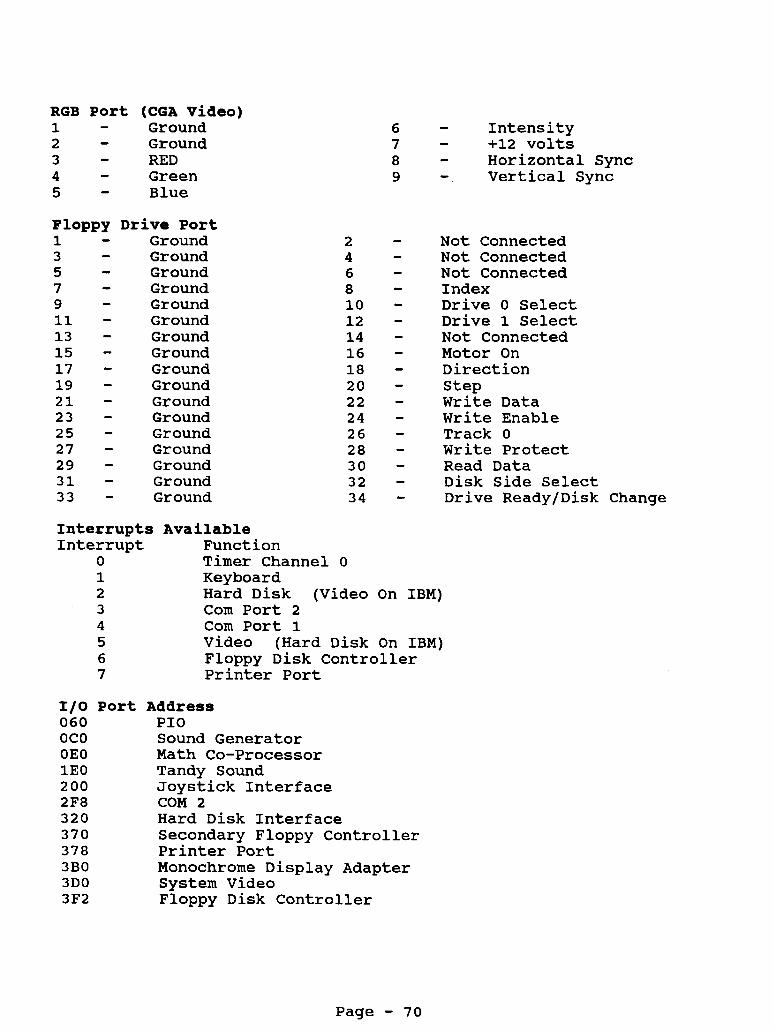
RGB Port (CGA Video) 1 - Ground 2 - Ground 3 - RED 4 - Green 5 - Blue
Floppy Drive Port 1 - Ground 3 - Ground 5 - Ground 7 - Ground 9 - Ground 11 - Ground 13 - Ground 15 - Ground 17 - Ground 19 - Ground 2 1 - Ground 23 - Ground 25 - Ground 27 - Ground 29 - Ground 3 1 - Ground 33 - Ground
6 - Intensity 7 - +12 volts 8 - Horizontal Sync 9 - . Vertical Sync
- 2 4 6 8 10 - 1 2 - 14 - 16 - 18 - 20 - 22 - 24 - 26 - 28 - 30 - 32 - 34 -
- - -
Not Connected Not Connected Not Connected Index Drive 0 Select Drive 1 Select Not Connected Motor On Direction Step Write Data Write Enable Track 0 Write Protect Read Data Disk Side Select Drive Ready/Disk Change
Interrupts Available Interrupt Function
0 Timer Channel 0 1 Keyboard 2 Hard Disk (Video On IBM) 3 Com Port 2 4 Corn Port 1 5 Video (Hard Disk On IBM) 6 Floppy Disk Controller 7 Printer Port
1/0 Port Address 060 PI0 OCO Sound Generator OEO Math Co-Processor 1EO Tandy Sound 200 Joystick Interface 2F8 COM 2 320 Hard Disk Interface 370 Secondary Floppy Controller 378 Printer Port 3B0 Monochrome Display Adapter 3D0 System Video 3F2 Floppy Disk Controller
Page - 7 0

Tandy lOOOA
Catalog Number 25-1000A
CPU Type CPU Speed Math Co-proc : Standard Memory: Total Memory : Video Memory : Expansion Slots: Video Output : Power Supply :
Keyboard Floppy Drive : Drive Bays Floppy Ctrl
Printer Port : Serial Port Joystick Ports : Other Ports
DOS Version Latest BIOS ROM:
8088 4.77 Mhz 8087 128K, on motherboard 640k, requires special memory cards
3 - 8 bit XT slots (10" long) CGA 61 Composite Monochrome 54 Watt
N/A
Tandy style 90 keys 1 - 5 1/4" 360K came standard 2 - 5 1/4" drive bays Low density
34 Pin card edge, built-in to motherboard
2 ports, 6 pin din connector Light Pen Port - DB 9 Composite Video - RCA connector Audio Output - RCA connector
N/A
MSDOS 2.11 01.01.00
This system is very similar to the 1000 (25-1000). The main differences are:
Math co-processor socket Newer BIOS ROM, ver 01.01.00 Fixed some technical problems found in the 1000.
lOOOA Motherboard Jumpers
E1-E2 connect clock crystal to circuit E3-E4 select continuous floppy drive ready (wired jumper) E6-E7 E8-E9 indicates there is no co-processor installed
connect printer select to parallel port
(remove E8-E9 when math co-processor is installed)
Note: E6-E7 should be removed to use of some IBM software and/or IBM compatible printers. programs that uses the status line for printer control. If you have an earlier version of the 1000 (non 1000A) there is a tech mod that can be done by Tandy that is equivalent to this jumper.
This may be necessary for some IBM
Page - 71

M e m o r y Boards
Tandy produces 3 different memory boards to be used in the 1000, lOOOA and 1000HD. The catalog numbers are:
25-1004 25-1009 25-1011
Several third party manufacturers have also produced memory boards for the 1000's. Some of these memory boards were also multifunction boards. This means that they also would have a clock/calendar and/or serial port built onto the memory board. Currently none of them are producing memory boards for the early 1000's anymore. If you are in need of a memory board, try asking around on Compuserve or Prodigy. Also check out your local computer shows.
The DMA circuitry for the system is on the memory boards. DMA chip will be one of the following chips:
The
8237A-5 8237AC-5 8237A-5P 8237AC-5P
25-1004 256K Memory Expansion Board
Expands system from 128K to 256K and from 256K to 384K.
This board came standard with 128K on it, with 2 rows of empty sockets for adding another 128K. This board only uses 64K x 1 drams. There are 4 jumper pins labeled El to E4. These jumpers are used to configure the memory board for the amount of memory and if there is a DMA chip present. The jumpers are located at the bottom of the memory board near the middle.
E1-E2 Off, indicates 128k of RAM on the board E1-E2 On, indicates 256K of RAM on the board
(Only install jumper if you have added the extra 128K to this board)
E3-E4 Off, indicates DMA chips is present. Do Not jumper these pins together on this board.
25-1009 2nd 128k Memory Expansion Board.
Expands system from 384K to 512K and from 512K to 640K.
This board came standard with 128K on it, with 2 rows of empty sockets for adding another 128K. This board only uses 64K x 1 drams. There are 4 jumper pins labeled El to E4. These jumpers are used to configure the memory board for the amount of memory. The jumpers are located at the bottom of the memory board near the middle. This board will not have a DMA chip.
Page - 72

E1-E2 Off, indicates 128k of RAM on the board El-E2 On, indicates 256K of RAM on the board
(Only install jumper if you have added the extra 128K to this board)
E3-E4 ON, indicates no DMA chip is present. This must be jumpered at all times.
Remember the 25-1004 board must be installed first and have 256k of memory on it before adding the 25-1009 memory board. Each memory board will use a slot.
25-1011 Memory Plus Expansion Board
Expands system from 128K up to 640K.
This memory board will only use 1 slot to expand your system to 640K. The memory board can use 64K x 1 or 256K x 1 chips, depending on the jumper settings. The jumpers are located at the bottom of the memory board, in the center. This board has three configurations:
2 banks of 64k chips El-E2 OFF E3-E4 Jumpered for 256K total
1 bank of 25633 chips El-F2 Jumpered E3-E4 OFF for 384K total
2 banks of 256k chips El-E2 OFF E3-E4 OFF for 640K total
This board also has a 62 pin connector located just above the card edge connector. This is also referred to as a Plus style connector. The reason for this connector was since the 1000, lOOOA and lOOOHD only had 3 expansion slots, this extra connector would give the customers a way to install more expansion cards. Tandy, along with other third party manufacturers, produced several boards such as a serial board, clock/calendar with Digi Mouse port, a 300 and 1200 baud modem and a network adapter that would fit onto this 62 pin plus connector.
CPU and Math Co-Processor Notes:
The CPU is an 8088 processor. You can replace this processor with a V-20 processor for improved performance. The math co- processor is installed in the empty socket located next to the CPU. Once you have installed the math co-processor you must remove the jumper at E8-E9.
Page - 73

1000 Floppy Disk Drives
5 1/4" 360K Floppy Drives
Teac FD-54B 5.25" 360k floppy disk drive (standard)
Teac FD-55B can also be used. Note: a longer floppy drive controller cable may be needed. Tandy part number W-0124.
The floppy drives are selectable as A: or B: through jumper settings on the floppy drive.
DSO = A: drive DS1 = B: drive DS2 = N/A on this system DS3 = N/A on this system
Note: The on-board floppy controller will support a 720K floppy drive as A: or B:. add a drivparm or driver.sys statement to your config.sys file. More information on installing a 5 1/411 floppy drive may be found on the "Secrets of the 1000'~~~ video.
Depending on the DOS version you may need to
3.5" 720K Floppy Drives
You can add a 3.5" 720K floppy drive to your system. You will need the following:
3.5" Floppy Drive 5 1/411 Mounting Frame MSDOS 3.2 or Higher Longer Floppy Drive Cable (optional, but helpful)
You will need to configure the drive to be either drive A: or drive B: by changing the drive select jumpers, like above with the 5 1/4" drives.
You will also need to add one of the two following lines to your config.sys file.
drivparm=/D: 0 <-- if the 3.5" drive is drive A:
drivparm=/D:l <-- if the 3.5" drive is drive B:
The drivparm command will inform MSDOS that the A: drive is a 720H floppy drive. If you don't add this line, the system will think that it is only a 360k floppy.
NOTE: It is possible to install a 1.2 or 1.44 meg floppy drive into this system. See the section on High Density Floppy Drives.
Page - 74

Hard Drives
This system will handle a hard drive or hard card.
If you are installing an MFM or RLL hard drive or hard card into this system you will have to have the controller card modified to use IRQ2 as the hard drive interrupt. If you are installing an IDE hard drive or hard card, just make sure it has a Tandy BIOS on the controller.
Serial Ports
This system does not have a built-in serial port, one can be added. Do not try to use the light pen port on the back of the system as a serial port. It is not electrically the same.
Clock Info
A clock chip can be installed into this system. See the chart for clock chips for the exact location.
Keyboard Notes:
The 1000, lOOOA and 1000HD do not use a standard keyboard interface. It is possible to connect a 101 style keyboard to these 1000's. You will either need a special keyboard converter Tandy part number 25-1030 (has been discontinued for awhile) or a keyboard with the converter built-in. Tandy produced a keyboard, model 25-4038 with a converter built-in.
There are also a couple of third party manufacturers that have made keyboards for the lOOO's, they are Datadesk and Northgate. When connecting up the Northgate keyboard, you will need to change the DIP switch setting found under the name plate.
Video Notes:
The on-board video cannot be disabled. Therefore, optional video boards will not work in this system.
This system supports monochrome and standard CGA along with an extended CGA mode. This is also referred to as TGA. Standard CGA will allow it to display 4 colors, where as the TGA mode will allow you to display up to 16 colors. Very similar to EGA, but without the higher resolution.
Page - 75

Display Modes
80 lines by 25 lines 40 lines by 25 lines
16 foreground colors / 8 background colors
Graphics Modes
Colors Resolution 4 320 x 200 16 320 x 200 16 160 x 200 2 640 x 200 4 640 x 200
Page - 76

Printer Port The
Pin 1 3 5 7 9 11 13 15 17 19 2 1 23 25 27 29 31 33
p r i n t e r p o r t is a 34 p i n card
U s e STROBE DATA0 DATA1 DATA2 DATA3 DATA4 DATA5 DATA6 DATA7 P r i n t e r ACK BUSY O u t of Paper BUSY Ground N o t Connected Ground Ground
Motherboard Power Connector 1 - +5 V o l t s 2 - +5 V o l t s 3 - +5 V o l t s 4 - Ground 5 - Ground 6 - Ground 7 - Ground 8 - -12 V o l t s 9 - +12 V o l t s
Port (DB 9) +5 v o l t s Ground Light Pen I N Light Pen Switch N o t Connected N o t Connected N o t Connected N o t Connected N o t Connected
P i n 2 4 6 8 10 1 2 1 4 16 18 20 22 24 26 28
32 34
3 0 ,
edge.
U s e Ground Ground Ground Ground Ground Ground Ground Ground Ground Ground Ground Ground N o t Connected P r i n t e r F a u l t P r i n t e r I n i t Auto Feed N o t Connected
Joystick Ports 1 - Y A x i s 2 - X A x i s 3 - Ground 4 - Switch f l 5 - +5 V o l t s 6 - Switch #2
Keyboard 1 2 3 4 5 6 7 8
- - - - - - - -
Connector Keyboard Data Keyboard Busy Ground Keyboard Clock +5 V o l t s Keyboard R e s e t Mul t i Data Mult i Clock
Page - 77

RGB Port (CGA Video) 1 - Ground 2 - Ground 3 - RED 4 - Green
Floppy Drive Port 1 - Ground 3 - Ground 5 - Ground 7 - Ground 9 - Ground 11 - Ground 13 - Ground 15 - Ground 17 - Ground 19 - Ground 21 - Ground 23 - Ground 25 - Ground 27 - Ground 29 - Ground 31 - Ground 33 - Ground
- 2 4 6 8 10 - 12 - 14 - 16 - 18 - 20 - 22 - 24 - 26 - 28 - 30 - 32 - 34 -
- - -
- Blue - Intensity - +12 volts - Horizontal Sync - Vertical Sync
Interrupts Available Interrupt Function
0 Timer Channel 0 1 Keyboard 2 Hard Disk (Video On IBM) 3 Com Port 2 4 Com Port 1 5 Video (Hard Disk On IBM) 6 Floppy Disk Controller 7 Printer Port
Not Connected Not Connected Not Connected Index Drive 0 Select Drive 1 Select Not Connected Motor On Direction Step Write Data Write Enable Track 0 Write Protect Read Data Disk Side Select Drive Ready/Disk Change
1/0 Port 060 OCO OEO 1EO 200 2F8 320 370 378 3B0 3D0 3F2
Address PI0 Sound Generator Math Co-Processor Tandy Sound Joystick Interface COM 2 Hard Disk Interface Secondary Floppy Controller Printer Port Monochrome Display Adapter System Video Floppy Disk Controller
Page - 78
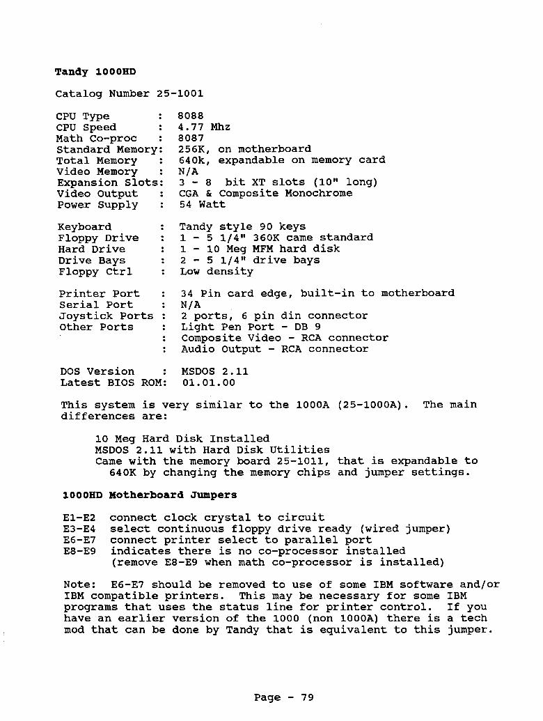
Tandy lOOOHD
Catalog Number 25-1001
CPU Type CPU Speed Math Co-proc : Standard Memory: Total Memory : Video Memory : Expansion Slots: Video Output : Power Supply :
Keyboard Floppy Drive : Hard Drive Drive Bays Floppy Ctrl
Printer Port : Serial Port Joystick Ports : Other Ports
DOS Version Latest BIOS ROM:
8088 4 . 7 7 Mhz 8087 256K, on motherboard 640k, expandable on memory card
3 - 8 bit XT slots ( lol l long) CGA & Composite Monochrome 54 Watt
N/A
Tandy style 90 keys 1 - 5 1 / 4 " 360K came standard 1 - 1 0 Meg MFM hard disk 2 - 5 1 / 4 " drive bays Low density
34 Pin card edge, built-in to motherboard N/A 2 ports, 6 pin din connector Light Pen Port - DB 9 Composite Video - RCA connector Audio Output - RCA connector MSDOS 2 . 1 1 0 1 . 0 1 . 0 0
This system is very similar to the lOOOA (25-1000A). differences are:
The main
1 0 Meg Hard Disk Installed MSDOS 2 . 1 1 with Hard Disk Utilities Came with the memory board 25-1011, that is expandable to
640K by changing the memory chips and jumper settings.
1000HD Motherboard Jumpers
El-E2 connect clock crystal to circuit E3-E4 select continuous floppy drive ready (wired jumper) E6-E7 E8-E9 indicates there is no co-processor installed
Note: IBM compatible printers. programs that uses the status line for printer control. If you have an earlier version of the 1000 (non 1 0 0 0 A ) there is a tech mod that can be done by Tandy that is equivalent to this jumper.
connect printer select to parallel port
(remove E8-E9 when math co-processor is installed)
E6-E7 should be removed to use of some IBM software and/or This may be necessary for some IBM
Page - 79

Memory Boards
This system came standard with the memory board 25-1011. This board is expandable to 640K.
The DMA circuitry for the system is on the memory board. The DMA chip will be one of the following chips:
8237A-5 8237AC-5 8237A-5P 8237AC-5P
25-1011 Memory Plus Expansion Board This memory board can use 64K x 1 or 256K x 1 chips, depending on the jumper settings. The jumpers are located at the bottom of the memory board, in the center. This board has three configurations:
2 banks of 64k chips El-E2 OFF E3-E4 Jumpered for 256K total
1 bank of 256k chips El-F2 Jumpered E3-E4 OFF for 384K total
2 banks of 256k chips El-E2 OFF E3-E4 OFF for 640X total
This board also has a 62 pin connector located just above the card edge connector. This was also referred to as a Plus style connector. The reason for this connector was since the 1000, lOOOA and lOOOHD only had 3 expansion slots, this extra connector would give the customers a way to install more expansion cards. Tandy, along with other third party manufacturers, produced several boards such as a serial board, clock/calendar with Digi Mouse port, a 300 and 1200 baud modem and a network adapter that would fit onto this 62 pin plus connector.
CPU and Math Co-Processor Notes:
The CPU is an 8088 processor. You can replace this processor with a V-20 processor for improved performance. The math co- processor is installed in the empty socket located next to the CPU. Once you have installed the math co-processor you must remove the jumper at E8-E9.
1000 Floppy Disk Drives
5 1 / 4 " 3 6 0 K Floppy Drives
Teac FD-54B 5.25" 360k floppy disk drive (standard)
Page - 80

Teac FD-55B can also be used. Note: A longer floppy drive controller cable may be needed. Tandy part number W-0124.
These floppy drives are selectable as A: or B: through jumper settings on the floppy drive.
DSO = A: drive DS1 = B: drive DS2 = N/A on this system DS3 = N/A on this system
Note: The on-board floppy controller will support a 720K floppy drive as A: or B:. Depending on the DOS version, you may need to add a drivparm or driver.sys statement to you config.sys file. More information on installing a 5 1/4" floppy drive may be found on the "Secrets of the 1000'~~~ video.
3.5" 720K Floppy Drives
You can add a 3.5" 720K floppy drive to your system. You will need :
3.5" Floppy Drive 5 1/4" Mounting Frame MSDOS 3.2 or Higher Longer Floppy Drive Cable (optional, but helpful)
You will need to configure the drive to be either drive A: or drive B: by changing the drive select jumpers, like above with the 5 1/418 drives.
You will also need to add one of the two following lines to your config.sys file.
drivparm=/D:O <-- if the 3.5" drive is drive A:
drivparm=/D:l <-- if the 3.5" drive is drive B:
The drivparm command will inform MSDOS that the A: drive is a 720K floppy drive. If you don't add this line, the system will think that it is only a 360k floppy.
NOTE: It is possible to install a 1.2 or 1.44 meg floppy drive into this system. See the section on High Density Floppy Drives.
Bard Drives
This system will handle a hard drive or hard card.
If you are installing an MFM or RLL hard drive or hard card into this system you will have to have the controller card modified to use IRQ2 as the hard drive interrupt. If you are installing an
Page - 81

IDE hard drive or hard card, just make sure it has a Tandy BIOS on the controller.
Serial Ports
This system does not have a built-in serial port, one can be added. system as a serial port.
Do not try to use the light pen port on the back of the It is not electrically the same.
C l o c k Info
A IlSmart" clock chip can be installed into this system. See the chart for clock chips for the exact location.
Keyboard N o t e s :
The 1000, l O O O A and lOOOHD do not use a standard keyboard interface. these 1000's. Tandy part number 25-1030 (has been discontinued for awhile) or a keyboard with the converter built-in. Tandy produced a keyboard, model 25-4038 with a converter built-in.
It is possible to connect a 101 style keyboard to You will either need a special keyboard converter
There are also a couple of third party manufacturers that have made keyboards for the lOOO's, they are Datadesk and Northgate. When connecting up the Northgate keyboard, you will need to change the DIP switch setting found under the name plate.
V i d e o N o t e s :
The on-board video cannot be disabled. Therefore, optional video boards will not work in this system.
This system supports monochrome and standard CGA along with an extended CGA mode. This is also referred to as TGA. Standard CGA will allow it to display 4 colors, where as the TGA mode will allow you to display up to 16 colors. Very similar to EGA, but without the higher resolution.
Display Modes
80 lines by 25 lines 40 lines by 25 lines 16 foreground colors / 8 background colors
Graphics Modes
Colors Resolution 4 320 x 200 16 320 x 200 16 160 x 200 2 640 x 200 4 640 x 200
Page - 82

Printer Port The printer port
Pin Use 1 3 - DATA0 5 - DATA1 7 - DATA2
DATA3 9 11 - DATA4 13 - DATA5 15 - DATA6 17 - DATA7
STROBE -
-
is a 34 pin
19 - 21 - 23 - 25 - 27 - 29 - 31 - 33 -
Printer ACK BUSY Out of Paper BUSY Ground Not Connected Ground Ground
Motherboard Power Connector 1 - +5 Volts 2 - +5 Volts 3 - +5 Volts 4 - Ground 5 - Ground 6 - Ground 7 - Ground 8 - -12 Volts 9 - +12 Volts
Light Pen Port (DB 9) 1 - +5 volts 2 - Ground 3 - Light Pen IN 4 - Light Pen Switch 5 - Not Connected 6 - Not Connected 7 - Not Connected 8 - Not Connected 9 - Not Connected
RGB Port (CGA Video) 1 - Ground 2 - Ground 3 4 - Green 5 - Blue
RED -
card
Pin 2 4 6 8 10 12 14 16 18 20 22 24 26 28 30 32 34
edge.
Use Ground Ground Ground Ground Ground Ground Ground Ground Ground Ground Ground Ground Not Connected Printer Fault Printer Init Auto Feed Not Connected
Joystick Ports - Y Axis 1 2 - X Axis 3 - Ground 4 - Switch #1 5 - +5 Volts 6 - Switch #2
Keyboard 1 2 3 4 5 6 7 8
- - - - - - - -
Connector Keyboard Data Keyboard Busy Ground Keyboard Clock +5 Volts Keyboard Reset Multi Data Multi Clock
6 - Intensity 7 - +12 volts 8 - Horizontal Sync 9 - Vertical Sync
Page - 83

Floppy Drive Port 1 - Ground 3 - Ground 5 - Ground 7 - Ground 9 - Ground 11 - Ground 13 - Ground 15 - Ground 17 - Ground 19 - Ground 21 - Ground 23 - Ground 25 - Ground 27 - Ground 29 - Ground 31 - Ground 33 - Ground
- 2 4 6 8 10 - 12 - 14 - 16 - 18 - 20 - 22 - 24 - 26 - 28 - 30 - 32 - 34 -
- - -
Not Connected Not Connected Not Connected Index Drive 0 Select Drive 1 Select Not Connected Motor On Direction Step Write Data Write Enable Track 0 Write Protect Read Data Disk Side Select Drive Ready/Disk Change
Interrupts Available Interrupt Function
0 Timer Channel 0 1 Keyboard 2 Hard Disk (Video On IBM) 3 Com Port 2 4 Com Port 1 5 Video (Hard Disk On IBM) 6 Floppy Disk Controller 7 Printer Port
1/0 Port 060 OCO OEO 1EO 200 2F8 320 370 378 3B0 3D0 3F2
Address PI0 Sound Generator Math Co-Processor Tandy Sound Joystick Interface COM 2 Hard Disk Interface Secondary Floppy Controller Printer Port Monochrome Display Adapter System Video. Floppy Disk Controller
Page - 84

Tandy 1000EX
Catalog Number 25-1050
CPU Type CPU Speed Math Co-proc : Standard Memory: Total Memory : Video Memory : Expansion Slots: Video Output : Power Supply :
Keyboard Floppy Drive : Hard Drive Drive Bays Floppy Ctrl Ext Floppy Port:
Printer Port : Serial Port Joystick Ports : Other Ports
DOS Version Latest BIOS ROM:
8088 4.77 Mhz / 7.16 Mhz Switchable
256K, on motherboard 640k, expandable on memory card N/A 1 Plus Style Connector CGA & Composite Monochrome 28 Watt
Tandy style 90 keys 1 - 5 1/4" 360K came standard
Low density 1 - External floppy drive port for 360K or 720K 34 Pin card edge, built-in to motherboard N/A 2 ports, 6 pin din connector Headphone Jack Composite Video - RCA connector MSDOS 2.11 01.02.00
There are two main motherboard revisions. Revision A and D
lOOOEX Motherboard
The EX has two main logic boards, revision A and D. The jumper settings are the same for both boards.
El-E2 off: pulls up printer select line to +5V (standard)
El-E2 should be removed to use of some IBM software and/or IBM This may be necessary for some IBM
on: connects printer select line to printer port
compatible printers. programs that uses the status line for printer control.
System Memory
The EX computer comes with 256k of RAM on the motherboard and is expandable to 640K with the following memory board.
EX/HX Memory Plus Expansion Adapter part number 25-1062. This board comes with 128K of memory on it and you can add a 256K memory kit to bring the total system memory up to 640K. There is a set of jumpers labeled
Page - 85

El, E2 and E3 that selects the amount of RAM that is installed on the memory board. They are as follows:
El-E2 Jumpered, selects only 128k on the memory board. This brings the total memory up to 384K.
256K memory kit is on the memory board. This brings the total memory up to 640K.
E2-E3 Jumpered, selects that 128K and the
The 128K memory that comes on the expansion board is made up of four (4) 64 x 4 150ns RAM chips. They plug into sockets U9 - U12 on the memory board. The 256k memory kit for this board is made up of eight (8) 256 x 1 150ns RAM chips. They plug into sockets Ul-U8 on the memory board.
There are several third party memory boards that will work in the lOOOEX and lOOOHX computers. These boards will take you to 640K and possibly beyond.
After installing the memory board, the system should boot up with either 384K or 640K memory, depending on how much memory was installed on the memory expansion board.
CPU and Math Co-Processor Notes:
The CPU is an 8088 processor. with a V-20 processor for improved performance. math co-processor socket.
You can replace this processor There is not a
Floppy Drive Notes
lOOOEX FD55BV 5.2511 360k Floppy Disk Drive
These floppy drives are selectable as A: or B: through jumper settings on the floppy drive.
DSO = A: drive DS1 = B: drive DS2 = N/A on this system DS3 = N/A on this system
The drive select jumpers are located on the bottom of the floppy drive, near the card edge connector for the floppy drive controller cable. The floppy drive must be set for DSO when installed inside the computer case.
Page - 86

It is possible to use a 3.5" 720K floppy drive in the EX as drive A. All you will need is a 3.5'l drive, the 5 1/4" mounting frame, MSDOS 3.2 or higher and you may need a longer floppy drive cable. You have to make sure that the drive select jumper on the 720K floppy drive is set to DSO. Then add this line to your config.sys:
drivparm=/D:O
The drivparm command will inform MSDOS that the A: drive is a 720K floppy drive. If you don't add this line the system will think that it is only a 360k floppy.
Plus Style Expansion Connector.
The lOOOEX and lOOOHX do not have standard expansion slots, instead they use a 62 pin expansion connector. memory board to your system, it will plug onto this connector and the memory board will contain either 1 or 2 additional expansion connectors, depending on the memory board manufacturer.
When you add a
The expansion boards you will use in this system are the Plus style expansion boards. Since they are not making any Plus style expansion cards anymore, several third party companies have come up with ways to connect a standard XT type expansion board into your system. This is usually done through an adapter. When using these adapters, the boards may fit in a little differently. However, the boards will work just fine, they just may install funny. When using these adapters, it may be best for you to leave the expansion slot cover on top of the computer off.
Hard Drives
Even though Tandy never brought out a hard drive for this system, many third party manufacturers did. Due to space limitations inside the system, the hard drive will have to be an external unit. You will need to have 384K of memory or higher and you will also need a hard disk controller card that has been setup for the EX or HX. to DOS 3.2 or higher.
You will also need to update your DOS version
Some of the external hard drives will have a power supply in the hard drive case. drive draws more power than the computer's power supply can handle. When using the newer 3.5" hard drives that are ltt high, it is possible to use the computer's power supply to run the hard disk, as these newer hard drives draw very little power.
This is only necessary when the external hard
You can use any brand hard drive, as long as you have the proper controller card. The controller must be designed for connection into the EX/HX. Also depending the type of controller card, you may need a special BIOS ROM on the hard disk controller.
Page - 87

Serial Ports
This system does not have a built-in serial port, added. system as a serial port.
one can be Do not try to use the light pen port on the back of the
It is not electrically the same.
Clock Notes:
A @@Smart@@ clock chip can be installed into this system. chart for clock chips for the exact location and software information.
See the
Keyboard Notes:
The keyboard is built-in to the case of the computer and is not interchangeable.
Video Notes:
This system supports monochrome and standard CGA along with an extended CGA mode. This is also referred to as TGA. Standard CGA will allow you to display 4 colors, where as the TGA mode will allow you to display up to 16 colors. but without the higher resolution.
Very similar to EGA,
Display Modes
80 lines by 25 lines 40 lines by 25 lines
16 foreground colors / 8 background colors
Graphics Modes
Colors Resolution 4 320 x 200 16 320 x 200 16 160 x 200 2 640 x 200 4 640 x 200
Page - 88

Printer Port The printer port is a 34 pin card edge.
Pin 1 3 5 7 9 11 13 15 17 19 21 23 25 27 29 31 33
Use - STROBE - DATA 0 - DATA 1 DATA 2 - DATA 3
- DATA 4 - DATA 5 - DATA 6 - DATA 7
-
Pin 2 4 6 8 10 12 14 16 18
Printer ACK 20 BUSY 22 Out of Paper 24 Select 26 Auto Feed 28 Not Connected 30 Ground 32 Ground 34
Audio Jack 1 - Ground 2 - Audio Out
Composite Video Center Video Out Outside Ground
(CGA Video) Ground Ground RED Green Blue Intensity Green - Mono Horizontal Sync Vertical Sync
Use Ground Ground Ground Ground Ground Ground Not Connected Ground Ground Ground Ground Ground Not Connected Printer Fault Printer Init Auto Feed Not Connected
Joystick Ports 1 - Y Axis 2 - X Axis 3 - Ground 4 - Switch #1 5 - +5 Volts
Switch #2 6 -
Page - 89

Floppy Drive Port - Internal 1 - Ground 3 - Ground 5 - Ground 7 - Ground 9 - Ground 11 - Ground 13 - Ground 15 - Ground 17 - Ground 19 - Ground 21 - Ground 23 - Ground 25 - Ground 27 - Ground 29 - Ground 31 - Ground 33 - Ground
Floppy Drive Port - External 1 - +12 volt 3 - +12 volt
Ground 5 7 - Ground 9 - Ground 11 - Ground 13 - Ground 15 - Side Select 17 - Direction 19 - Write Protect 21 - Read Data 23 - Write Date 25 - Write Enable 27 - Not Connected 29 - Ext Drive Select
-
Interrupts Available Interrupt Function
0 Timer Channel 1 Keyboard 2 Video 3 Corn Port 2 4 Corn Port 1 5 Hard Disk
2 4 6 8 10 12 14 16 18 20 22 24 26 28 30 32 34
2 4 6 8 10 12 14 16 18 20 22 24 26 28 30
0
Not Connected Not Connected Not Connected Index Drive 0 Select Not Connected Not Connected Motor On Direction Step Write Data Write Enable Track 0 Write Protect Read Data Disk Side Select Not Connected
+5 volt +5 volt +5 volt +5 volt Index Track 0 Step Motor On Ground Ground Ground Ground Ground +12 volt +12 volt
6 Floppy Disk Controller 7 Printer Port
Page - 90

1/0 Port 060 OCO OEO 1EO 200 2F8 320 370 378 3B0 3D0 3F2 3F8
Address PI0 Sound Generator Math Co-Processor Tandy Sound Joystick Interface COM 2 Hard Disk Interface Secondary Floppy Controller Printer Port Monochrome Display Adapter System Video Floppy Disk Controller COM 1
Page - 91

Tandy lOOOHX
Catalog Number 25-1053
CPU Type CPU Speed Math Co-proc : Standard Memory: Total Memory : Video Memory : Expansion Slots: Video Output : Power Supply :
Keyboard Floppy Drive : Hard Drive Drive Bays Floppy Ctrl Ext Floppy Port:
Printer Port : Serial Port Joystick Ports : Other Ports
DOS Version Latest BIOS ROM:
8088 4 . 7 7 Mhz / 7 . 1 6 Mhz Switchable
256K, on motherboard 640k, expandable on memory card N/A 1 Plus Style Connector CGA & Composite Monochrome 28 Watt
Tandy style 90 keys 1 - 3 . 5 " 720K came standard
2 - 3 . 5 " internal drive bays Low density 1 - External floppy drive port for 360K or 720K
34 Pin card edge, built-in to motherboard
2 ports, 6 pin din connector Headphone Jack Composite Video - RCA connector
N/A
MSDOS 2 . 1 1 In ROM 0 2 . 0 0 . 0 0
lOOOHX Motherboard
The HX has only one jumper setting, that is:
E1-E2 off: pulls up printer select line to +5V (standard) on: connects printer select line to printer port
E1-E2 should be removed to use of some IBM software and/or IBM compatible printers. that uses the status line for printer control.
This may be necessary for some IBM programs
System Memory
The HX computer comes with 256k of RAM on the motherboard. It is made up of 8 - 64 x 4 DRAMS. The memory is expandable to 640K with the following memory board.
EX/HX Memory Plus Expansion Adapter part number 25-1062. This board comes with 128K of memory on it and you can add a 256K memory kit to bring the total system memory up to 640K. There is a set of jumpers labeled E l , E2 and E3 that selects the amount of RAM that is
Page - 92
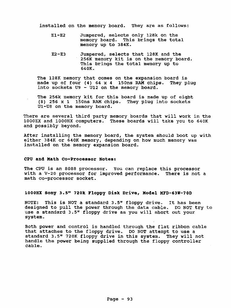
installed on the memory board. They are as follows:
El-E2 Jumpered, selects only 128k on the memory board. memory up to 384K.
This brings the total
E2-E3 Jumpered, selects that 128K and the 256K memory kit is on the memory board. This brings the total memory up to 640K.
The 128K memory that comes on the expansion board is made up of four (4) 64 x 4 150ns RAM chips. They plug into sockets U9 - U12 on the memory board. The 256k memory kit for this board is made up of eight (8) 256 x 1 150ns RAM chips. They plug into sockets Ul-U8 on the memory board.
There are several third party memory boards that will work in the lOOOEX and lOOOHX computers. These boards will take you to 640K and possibly beyond.
After installing the memory board, the system should boot up with either 384K or 640K memory, depending on how much memory was installed on the memory expansion board.
CPU and Math Co-Processor Notes:
The CPU is an 8088 processor. with a V-20 processor for improved performance. There is not a math co-processor socket.
You can replace this processor
lOOOHX Sony 3.5" 720k Floppy Disk Drive, Model MFD-63W-70D
NOTE: This is NOT a standard 3.5'l floppy drive. It has been designed to pull the power through the data cable. use a standard 3.511 floppy drive as you will short out your system.
DO NOT try to
Both power and control is handled through the flat ribbon cable that attaches to the floppy drive. standard 3.5" 720K floppy drive in this system. They will not handle the power being supplied through the floppy controller cable.
DO NOT attempt to use a
Page - 93

The floppy drive model that was used is the Sony MP-F63-70D. Drive selection is through a slide switch on the side of the drive .
DSO = A: drive, slide switch positioned all way to
DS1 = B: drive, slide switch positioned second notch the rear of the floppy drive.
from the rear of the floppy drive.
NOTE: A modified Teac FD235-F and FD235HF can also be used. This drive has to be modified to handle the power through the flat ribbon cable.
Since this drive has been discontinued, several third party companies have come out with replacement drives. are a modified version of a standard 3.5" floppy drive. modified drives have been setup to accept power through the flat ribbon data cable. drives and you may find the face plate a little darker than the white case. However, these drives, when modified, fit and work just fine in the HX.
These drives These
These third party drives are normally TEAC
If you decide to use a higher version of MSDOS on the HX, you may need to add the drivparm line to your config.sys file.
drivparm=/D:O <-- For drive A
drivparm=/D:l <-- For drive B
The drivparm command will inform MSDOS that the A: drive is a 720K floppy drive. If you don't add this line, the system will think that it is only a 360k floppy.
Plus Style Expansion Connector.
The lOOOEX and lOOOHX do not have standard expansion slots, instead they use a 62 pin expansion connector. memory board to your system, it will plug onto this connector and the memory board will contain either 1 or 2 additional expansion connectors, depending on the memory board manufacturer.
The expansion boards you will use in this system are the Plus style expansion boards. Since they are not making any Plus style expansion cards anymore, several third party companies have come up with ways to connect a standard XT type expansion board into your system. This is usually done through an adapter. When using these adapters, the boards may fit in a little differently. However, the boards will work just fine, they just may install funny. leave the expansion slot cover on top of the computer off.
When you add a
When using these adapters, it may be best for you to
Page - 94

Hard Drives
Even though Tandy never brought out a hard drive for this system, many third party manufacturers did. You can install either an internal hard disk or an external hard disk. Generally the internal hard disks will cost less, therefore are more popular. When installing the hard disk internally, you will need to remove the B: floppy drive, as this is where the hard disk will fit. You will need to have 384K of memory or higher and you will also need a hard disk controller card that has been setup for the EX or HX. You will also need to update your DOS version to DOS 3.2 or higher.
You will need to run the SETUPHX program and set the system for:
Primary Start-up Device DISK Initial Start-up Program MS-DOS
This way the hard drive and new DOS can bypass the built-in DOS and boot directly from the hard disk.
We recommend only using a 1" high 3.5" hard disk or smaller inside the HX. These hard drives draw very little power from the power supply. When you remove the B: floppy drive, you may be left with an open space where the B: floppy drive face plate was. An easy way to cover this opening is to get a piece of plastic from a hobby shop, paint it white, then glue it to the inside cover of the computer case.
You can use any brand hard drive, as long as you have the proper controller card. The controller must be designed for connection into the EX/HX. you may need a special BIOS ROM on the hard disk controller.
Also depending on the type of controller card,
The EX Setup Program
This computer has part of MSDOS 2.11 built-in to the ROM. This allows you to simply turn on the computer and boot to a DOS prompt without having to insert a floppy disk into drive A.
Also contained in ROM is Deskmate. some support programs are in the ROM. The rest of Deskmate is on diskettes.
The main desktop menu and
There is also an EEPROM in the system that contains such information as type of video display, prompt for date and time, number of disk drives, etc. drive you must run the SETUPHX to update the system configuration.
Whenever you add or remove a disk
Page - 95

If you are running a program that requires the use of a config.sys file or autoexec.bat file and you are booting from ROM, then make the following changes in the SETUPHX program.
Check For Config.sys On Drive A YES Check For Autoexec.bat On Drive A YES
Then create the config.sys and/or autoexec.bat file on a disk and leave it in the A: drive when booting. Also copy any files that are needed or called for in the config.sys or autoexec.bat to this floppy disk. The system will boot from ROM then read drive A: for the config.sys or autoexec.bat file.
Using A Higher Version DO8
You will need to boot the system with the old version DOS and run the SETUPHX program. Set the system for:
Primary Start-up Device DISK Initial Start-up Program MS-DOS
Save the setup and reboot the system.
From now on, the computer will boot from a higher version DOS disk, when placed in drive A or from a hard disk.
Serial Ports
This system does not have a built-in serial port, added. system as a serial port.
Clock Notes:
one can be Do not try to use the light pen port on the back of the
It is not electrically the same.
A llSmartll clock chip can be installed into this system. chart for clock chips for the exact location and software information.
See the
Video Notes:
This system supports monochrome and standard CGA along with an extended CGA mode. This is also referred to as TGA. Standard CGA will allow you to display 4 colors, where as the TGA mode will allow you to display up to 16 colors. but without the higher resolution.
Very similar to EGA,
Page - 96

Display Modes
80 lines by 25 lines 40 lines by 25 lines
16 foreground colors / 8 background colors
Graphics Modes
Colors Resolution 4 320 x 200 16 320 x 200 16 160 X 200 2 640 X 200 4 640 X 200
Page - 97

Printer Port The printer port is a 34 pin card edge.
Pin 1 3 5 7 9 11 - 13 - 15 - 17 - 19 - 21 - 23 - 25 - 27 - 29 - 31 - 33 -
- - - - -
Use STROBE DATA 0 DATA 1 DATA 2 DATA 3 DATA 4 DATA 5 DATA 6 DATA 7 Printer ACK BUSY Out of Paper Select Auto Feed Not Connected Ground Ground
A u d i o Jack 1 - Ground 2 - Audio Out
C o m p o s i t e V i d e o Center Video Out Outside Ground
RGB Port (CGA V i d e o ) 1 - Ground 2 - Ground 3 4 - Green 5 - Blue 6 - Intensity 7 - Green - Mono a - Horizontal Sync 9 - Vertical Sync
RED -
Pin 2 4 6 8 10 - 12 - 14 - 16 - 1% - 20 - 22 - 24 - 26 - 28 - 30 - 32 - 34 -
- - - -
Use Ground Ground Ground Ground Ground Ground Not Connected Ground Ground Ground Ground Ground Not Connected Printer Fault Printer Init Auto Feed Not Connected
Joystick P o r t s 1 - Y Axis 2 - X Axis 3 - Ground 4 5 - +5 Volts 6
Switch fl
Switch #2
- -
Page - 98

Floppy Drive Port - Internal 1 - Not Connected 3 - + 5 Volts 5 - + 5 Volts 7 - + 5 Volts 9 - + 5 Volts 11 - + 5 Volts 13 - Ground 15 - Ground 17 - Ground 19 - Ground 21 - Ground 23 - Ground 25 - Ground 27 - Ground 29 - + 12 Volts 31 - + 12 Volts 33 - + 12 Volts
2 4 6 8 10 12 14 16 18 20 22 24 26 28 30 32 34
NOTE: Power is supply on the floppy These lines are normally ground lines.
Not Connected Not Connected Not Connected Index Drive 0 Select Not Connected Not Connected Motor On Direction Step Write Data Write Enable Track 0 Write Protect Read Data Disk Side Select Not Connected
drive controller cable.
Floppy Drive Port - External 1 - +12 volt 3 - +12 volt 5 - Ground 7 - Ground
Ground 9 11 - Ground 13 - Ground 15 - Side Select 17 - Direction 19 - Write Protect 21 - Read Data 23 - Write Date 25 - Write Enable 27 - Not Connected 29 - Ext Drive Select
-
2 4 6 8 10 12 14 16 18 20 22 24 26 28 30
Interrupts Available Interrupt Function
0 Timer Channel 0 1 Keyboard 2 Video 3 Corn Port 2 4 Corn Port 1 5 Hard Disk 6 Floppy Disk Controller 7 Printer Port
+5 volt +5 volt +5 volt +5 volt Index Track 0 Step Motor On Ground Ground Ground Ground Ground +12 volt +12 volt
Page - 99

1/0 Port 060 OCO OEO 1EO 200 2F8 320 370 378 3B0 3D0 3F2 3F8
Address PI0 Sound Generator Math Co-Processor Tandy Sound Joystick Interface COM 2 Hard Disk Interface Secondary Floppy Controller Printer Port Monochrome Display Adapter System Video Floppy Disk Controller COM 1
Page - 100

Tandy lOOORL Tandy 1000RL-ED
Catalog Number 25-1450 (1OOORL) Catalog Number 25-1451 (1000RL-HD)
CPU Type CPU Speed Math Co-proc : Standard Memory: Total Memory : Video Memory : Expansion Slots: Video Output : Power Supply :
Keyboard Floppy Drive : Hard Drive Drive Bays Floppy Ctrl Ext Floppy Port:
Printer Port : Serial Port Joystick Ports : Other Ports
DOS Version Latest BIOS ROM:
8086 4.77 Mhz / 9.44 Mhz Switchable
512K, on motherboard 768K 128K, when system is at 768K memory 1 XT style, 10" long CGA & Monochrome 25 Watt
101 style keyboard, PS/2 connector 1 - 3.5" 720K came standard 1 - 20 or 40 meg hard disk on RL-HD model only 2 - 3.5" internal drive bays Low density
DB-25, built-in to motherboard
2 ports, 6 pin din connector Headphone Jack Microphone PS/2 Mouse Port
DB-9
MSDOS 3.3 In ROM 02.00.01
This system has part of DOS in ROM. Therefore, if your system only has floppy drives, you will have a drive C:, which is the ROM. If you system has a hard drive, drive D: or E: will be the ROM. If you are using a higher version of DOS than DOS 3.3 which came with the system, the ROM will be turned off.
WARNING: D o n o t t u r n t h e power off and then on r i g h t away. to t h e power draw by t h e hard drive, you may damage the power
Due
supply!
lOOORL Motherboard Jumper Settings
E12-El3 connects the video interrupt to IRQ5. This is for some of the older software that was written specifically for the original 1000. Note: This jumper setting may cause your video to roll if some other device is using this interrupt, such as some hard drive controllers.
Page - 101

E13-El4 connects the hard drive interrupt, IRQ5 to the IDE hard drive port. (Default Setting)
E14-El5 connects IRQ2 to the hard drive IDE port. It is really not recommended to use this setting. Not all software will run correctly on IRQ2.
E2-E3 connects SLCTIN (select interrupt) to the printer port. E3-E4 disconnects SLCTIN from the printer port.
On some motherboards E12, E13, E14 and E15 may be labeled as:
VSYNC IRQ5 <---- HDIRQ <---- IRQ2
Jumper IRQ5 with HDIRQ (default) I There is another jumper setting on the small satellite board located at the top inside rear of the computer. There are three jumper pins, with the center being common. This is how they are marked and your choices are:
E6 Microphone Input <---- + I
E7 Common Pin <---- + I
E8 Line Audio Input <---- + Place the jumper on either the common pin and the microphone input or the common pin and the line audio input.
Microphone Input: For connecting a microphone to the computer input.
Line Audio Input: Allows you to input line-level output from music keyboards, stereos and other audio equipment.
Main Logic Board Chips
u1 u3 u4 U6 U15
U16 U17 U18 U27 U2 8 U2 9 U3 0
Custom IC for floppy support Character generator Floppy controller Video controller Keyboard, PS/2 mouse interface, floppy interface, interrupt controller Printer, sound, joystick and serial port controller 8086 CPU Setup EEPROM DMA, DRAM controller Clock chip socket Real time clock on RL-HD only ROM BIOS
Page - 102

System Memory
The RL and RL-HD computer comes with 512K of RAM on the motherboard and is expandable to 768K directly on the motherboard. You will need to install 2 - 256k x 4 dram chips into sockets U19 and U23.
This will provide you with a total memory of 768K. One important note is that the memory above 640k is used for video RAM. Before you installed the 256K memory upgrade, the video would use some of the 512k base memory for video RAM. By installing the extra 256k memory, you not only upgrade to 640k, but you stop the video from using any of the lower 640k since the video will have its own 128k of memory.
CPU and Math Co-Processor Notes:
The CPU is an 8086 processor and it is not changeable. not a math co-processor socket.
There is
lOOORL h RL-ED 3.5" 720K Floppy Drive, Teac FD235F-105U
Floppy Drive Jumper Settings
DO - Drive select 0 D1 - Drive select 1
On some models of the Teac floppy drive, the DO and D1 may be labeled as DSO and DS1. Left pins of RY and DC should be jumpered. (connects ready input to pin 34 of ribbon cable signal, all other jumpers should be off. Power is drawn from the ribbon cable.
NOTE: This is NOT a standard 3.5" floppy drive. It has been designed to draw the power through the data cable. use a standard 3.5" floppy drive, as you will short out your system.
DO NOT try to
Teac is well known for changing the part numbers on their drives. The above listed model number is for the factory supply drive. There are other models of the Teac drives that will work in the RL and RL-HD. These drives are a modified version of a standard 3.5" floppy drive. These modified drives have been setup to accept power through the flat ribbon data cable. Make sure when you order an A: or B: drive for the RL and RL-HD that it has the correct eject button. cut up your computer case in order to install their drives. The proper drive will have no face plate and have a blue eject button. The RL and RL-HD has the floppy drive face plate built- in to the case.
Some third party companies will have you
Page - 103

Hard Drives
The F& and RL-HD has a built-in IDE interface. It is an XT IDE interface, however it is not the same as the industry standard AT IDE interface. It looks like an AT IDE interface, but it is electrically different. or 40 meg XT IDE hard drive. drive connected to the XT interface on the motherboard! three models recommended for this system are:
The XT interface will only support a 20 DO NOT try to use an AT interface
The only
Seagate ST325X 20 Meg Hard Disk Seagate ST351A/X 4 0 Meg Hard Disk Seagate ST352A/X 40 Meg Hard Disk
The ST351A/X and ST352A/X are really the same drive. these drives are XT and AT interface switchable by changing the jumper settings found on the side of the drive. information see Tech Notes & Jumper Manual Vol 2.
Both of
For more
Tandy calls these hard drives IISmart Drives". It's their name for IDE Hard Drives. When you purchase one of these hard drives from Tandy, they will supply you a disk to partition the hard disk, format it, and install Deskmate. This process takes about an hour on the 40 meg hard drive.
If you purchase your hard drive from a third party company, they will usually come pre-formatted, so all you have to do is copy DOS onto the hard disk. partition the hard disk yourself and format it following their instructions. This should take no more then 10 minutes. Just remember, always follow the directions sent with the drive from the place you purchased it from!
In the worst case, you would have to
NOTE: Never run HSECT or AUTOFMT on these hard drives. It can render them useless. we will have more instructions on that in Vol 2.
We have a way to recover the drives though,
Let's say you want to install a larger than 4 0 meg hard drive into your system. has an IDE controller with a Tandy BIOS ROM.
Notes: hard drive can be installed.
You can! You will need a hard drive kit that
Only 2 floppy disk drives or 1 floppy disk drive and 1
ST35lAp Jumper Setting
JP1 is toward the front of the drive, JP9 is closest to the rear of the drive.
JP1 1-2 Not jumpered JP2 3-4 Jumpered JP3 5-6 Not jumpered JP4 7-8 Not jumpered
Page - 104

JP5 9-10 Jumper ed JP6 11-12 Not jumpered JP7 13-14 Not jumpered JP8 15-16 Not jumpered JP9 17-18 Jumpered
T h e RL Setup P r o g r a m
The SETUPRL program gives you access to the system's setup configuration. It is important to run this program when installing floppy disk drives, video options, startup boot options, configuration options, etc.
NOTE: SETUPRL /A option will give you additional setup information for video memory size, certain chip selects, network options, etc. Be careful when running the /A option.
Tech Note: You can change the video mode from monochrome and color by using the following key sequence during bootup:
<CTRL><ALT><SHIFT><V>
This means you would hold down the CTRL key, then hold down the ALT key, then hold down the SHIFT key and then press the V key, while keeping other keys held down.
If you are running a program that requires the use of a config.sys file or autoexec.bat file and you are booting from ROM, then make the following changes in the SETUPRL program.
Check For Config.sys On Drive A or C Check For Autoexec.bat On Drive A or C
Seiect A drive if you only have floppy drives. Select C drive if you have a hard drive.
Using A H i g h e r V e r s i o n DO8
You will need to boot the system with the old version DOS and run the SETUPRL program. Set the system for:
Primary Start-up Device DISK Initial Start-up Program MS-DOS
Save the setup and reboot the system.
From now on, the computer will boot from a higher version DOS disk, when placed in drive A: or from a hard disk.
Page - 105

Clock Chip N o t e s
The smartwatch or clock chip option is installed in the 28 pin socket at U28. You do not need any clock software to set the clock or run it. Simply install the clock then set the date and time by using the DATE command and TIME command from the DOS prompt. When a clock is installed the system will automatically detect it and when you issue the DATE and TIME command it will automatically set the date and time in the clock chip.
The RL-HD (25-1451), has a Lithium CMOS battery on the motherboard. This battery is also for the built-in Smartwatch on this model only. NOTE: This may not apply to all RL-HD models.
P o w e r Supply
There is a 25 watt power supply in this system. The power supply is cooled by vents rather than a cooling fan. This is the same power supply used in the 1000 RL, RLX, RLX-B and RSX.
External Floppy Drive Support
The RL and RL-HD has the printer port set for uni-directional. The external floppy drive need the printer port set for bi- directional. Under the satellite board there are three solder pads labeled E2-E3-E4. You need to solder E2 to E3 to enable the printer port to work in bi-directional mode.
You will need to install the driver EXTDRVR.SYS in the config.sys file for the external drive to function.
Serial Port
The serial port has a 9 pin connector located on the back of the computer. through the SETUPRL program.
You can change the serial port from COM 1 to COM 2
Mouse N o t e s :
The RL and RL-HD use a PS/2 style mouse. If your Deskmate randomly locks up when using the PS/2 style mouse with the RL or RL-HD, then change the ROM to the 02.00.01 version. There is a compatibility problem between the mouse driver in the ROM and Deskmate. The new ROM has a revised mouse driver.
We have noted that some software will not work with the PS/2 mouse on RL and RL-HD, even though the software has the PS/2 style mouse as an option. If that happens, you will need to use a serial mouse.
Page - 106

Video Notes:
This system supports Hercules Graphics (monochrome) and standard CGA along with an extended CGA mode. This is also referred to as TGA. Standard CGA will allow you to display 4 colors, whereas the TGA mode will allow you to display up to 16 colors.
The RL and RL/HD only has one video connection on the back of the computer. You can connect either a CGA or Mono monitor to the video port. when changing from CGA to Mono or Mono to CGA. This can be done by pressing CTRL + ALT + SHIFT + V all at the same time. This will cause the video mode to switch and the system to reboot.
You will need to change the mode of the video port
CGA: By running SETUPRL /A, you can adjust the amount of video memory the system is using. If you have 768K of memory installed and you are having problems with programs not displaying their screen or loss of sound or lockups when running some programs, try adjusting the amount of memory used for the video. This seems to fix alot of problems with Sierra games and children's software . Display Modes
80 lines by 25 lines 40 lines by 25 lines
16 foreground colors / 8 background colors
Graphics Modes
Colors Resolution 4 320 x 200 16 320 x 200 16 160 x 200 2 640 x 200 4 640 x 200 16 640 x 200
Mono 720 x 348 Hercules Graphics Mode
VGA: This system can use VGA, however, it will use the system's only expansion slot. VGA card must be able to run in an 8 bit mode. You will also need a VGA monitor, the CMll or CM5 are not VGA monitors.
Page - 107

Printer Port - The printer port is a DB Pin 1 3 5 7 9 11 - 13 - 15 - 17 - 19 - 21 - 23 - 25 -
- - - - -
Use STROBE DATA 1 DATA 3 DATA 5 DATA 7 Busy Select Printer Fault Select In Ground Ground Ground Ground
Audio Jack 1 - Audio Sound 2 - Ground
RGB Port (CGA Video) 1 - Ground 2 - Ground 3 4 - Green 5 - Blue
RED -
Floppy Drive Port - Internal 1 - Not Connected 3 - + 5 Volts 5 - + 5 Volts 7 - + 5 Volts 9 - + 5 Volts 11 - + 5 Volts 13 - Ground 15 - Ground 17 - Ground 19 - Ground 21 - Ground 23 - Ground 25 - Ground 27 - Ground 29 - + 12 Volts 31 - + 12 Volts 33 - + 12 Volts
Pin 2 4 6 8 10 - 12 - 14 - 16 - 18 - 20 - 22 - 24 -
- - - -
25 connector.
Use Data 0 Data 2 Data 4 Data 6 Printer Acknowledge Paper Out Auto Feed Initialize Ground Ground Ground Ground
1 2 3 4 5 6
6 7 8 9
- 2 4 6 8 10 - 12 - 14 - 16 - 18 - 20 - 22 - 24 - 26 - 28 - 30 - 32 - 34 -
- - -
Joystick Ports - Y Axis - X Axis - Ground - Switch #l - +5 Volts - Switch #2
- Intensity - Green - Mono - Horizontal Sync - Verticalsync
NOTE: Power is supply on the floppy These lines are normally ground lines.
Not Connected Not Connected Not Connected Index Drive 0 Select Drive 1 Select Not Connected Motor On Direction Step Write Data Write Enable Track 0 Write Protect Read Data Disk Side Select Disk Change
drive controller cable.
Page - 108

Keyboard Connector 1 - Data 2 - Not Used 3 - Ground 4 - +5 Volts 5 - Clock 6 - Not Used
PS/2 Mouse 1 - Data
Not Used 2 3 - Ground
+5 Volts 4 5 - Clock 6 - Not Used
- -
Serial Port CD 1 RD 2 TD 3 DTR 4 SG 5
6 - CTS 7 - RTS 8 9
- - - - -
cs RI
- -
Carrier Detect Receive Data Transmit Data Data Terminal Ready Signal Ground Clear to Send Request to Send Clear To Send Ring Indicator
Power Supply Connector 1 - -12 volts 2 - +12 volts 3 - Ground
4 - Ground 5 - +5 volts 6 - +5 volts
Interrupts Available Interrupt Function
0 Timer Channel 0 1 Keyboard 2 Video 3 Com Port 2 4 Corn Port 1 5 Hard Disk 6 Floppy Disk Controller 7 Printer Port
1/0 Port Address 060 PI0 OCO Sound Generator OEO Math Co-Processor 1EO Tandy Sound 200 Joystick Interface 2F8 COM 2 320 Hard Disk Interface 370 Secondary Floppy Controller 378 Printer Port 3B0 Monochrome Display Adapter 3D0 System Video 3F2 Floppy Disk Controller 3F8 COM 1
Page - 109

Tandy lOOORLX Tandy 1000RLX-ED
Catalog Number 25-1452 (1OOORLX) Catalog Number 25-1453 (1000RLX-HD)
CPU Type CPU Speed Math Co-proc : Standard Memory:
Total Memory : Expansion Slots: Video Output : Power Supply :
Keyboard Floppy Drive : Hard Drive Drive Bays Floppy Ctrl Ext Floppy Port:
Printer Port : Serial Port Joystick Ports : Other Ports
DOS Version Latest BIOS ROM:
80286 5 Mhz / 10 Mhz Switchable
512K, on motherboard (RLX) 1 Meg on motherboard (RLX-HD) 1 Meg 1 XT style, 10" long VGA 25 Watt
101 style keyboard, PS/2 connector 1 - 3.5" 1.44 Meg came standard 1 - 40 meg hard disk on RLX-HD model only 2 - 3.5" internal drive bays High Density
DB-25, built-in to motherboard
2 ports Headphone Jack Microphone PS/2 Mouse Port
DB-9
MSDOS 3.3 In ROM 02.00.00
This system has a 80286 processor running at 10 Mhz. The 80286 chip has two modes of operation, Real Mode (8086) and Protected Mode (80286).
This system has part of DOS in ROM. Therefore, if your system only has floppy drives, you will have a drive C, which is the ROM. If you system has a hard drive, drive D: or E: will be the ROM. If you are using a higher version of DOS than DOS 3.3 which came with the system, the ROM will be turned off.
There is a program in ROM called RESTART.COM. This program will allow you to reboot the system into Deskmate.
Page - 110

lOOORLX Motherboard
Jumper Settings
E2-E3 VGA on IRQ 3, No jumper - disable (Default) VGA on IRQ 3, Jumper - Enable
E4-E5 Floppy Controller Primary (3FO-3F7) (Default) E5-E6 Floppy Controller Secondary (370-377)
E7-E8 Disable built-in VGA E8-E9 Enable built-in VGA (Default)
E10-E11 Map Video BIOS at F0000-F7FFF and C0000-C7FFF (Default) Ell-El2 Disable dual mapping of video Bios
There is another jumper setting on the small satellite board located at the top inside rear of the computer. jumper pins, with the center being common. marked and your choices are:
There are three This is how they are
E6 Microphone Input <---- + I I
E7 Common Pin <---- + E8 Line Audio Input <---- +
E6-E7 Microphone Input, allows you to connect a microphone
E7-E8 Line Audio Input, allows you to connect input from
to the computer.
line-level output from music keyboard, stereos, etc.
Main Logic Board Chips
u2 - u3 - u5 - U6 - u12 - U13 - u19 - U28 - U32 - u33 -
Mouse, Keyboard, Interrupt Controller Setup EEPROM VGA controller VGA RAMDAC IC Floppy controller Sound, Printer, Serial, Joystick Controller 80L286 10 Mhz CPU (low power) system controller BIOS ROM Clock chip
U9 and U10 64k x 16 video RAM U15 to U18 256k x 4 system RAM = 512k
Page - 111

System Memory
The RLX comes with 512K of RAM on the motherboard and is expandable to 1 meg directly on the motherboard. to install 4 - 256k x 4 ZIP chips into sockets U23, U24, U25 and U26. Please note these are not DRAM chips but ZIP chips. These may be a little hard to find.
You will need
The RLX/HD came with 1 meg of RAM installed.
The area above 640k can be accessed for loading DOS high with DOS 5.0 or higher. beginning of the config.sys file:
You will need to add the following line to the
DEVICE=C:\DOS\HIMEM.SYS /M:PS2 DOS=HIGH
System Memory Map
With 512K With 1 Meg Description
000000-07FFFF 000000-07FFFF 080000-09FFFF
OA0000-OBFFFF OA0000-OBFFFF OC0000-OC7FFF OC0000-OC7FFF OC8000-ODFFFF OC8000-ODFFFF OE0000-OEFFFF OE0000-OEFFFF OF0000-OFFFFF OF0000-OFFFFF
100000-15FFFF
512K System RAM 128K System RAM Video RAM 256K Reserved For Video BIOS Expansion Card Use 64K paged ROM 64k system RAM 384k system RAM
100ORLX h RLX-HD 3.5" 1.44 Meg Floppy Drive
The 1.44 meg Teac FD235HF-106U or the Sony MP-Fl7W-70D may be used in this system.
Floppy Drive Jumper Settings
DO - Drive select 0 D1 - Drive select 1
FG: DO: D1: HHI : LHI : OP: HHO: D2: D3:
Frame ground. Permanent installation Drive select zero (default) Drive select one Logic HI sets the drive in high density mode (not used) Logic LOW sets the drive in high density mode (not used) High density switch enabled (jumpered) High density output on high (not used) Drive select 2. Jumper between D2 and center pin Drive select 3. Jumper between D3 and center pin
On some models of the Teac floppy drive, the DO and D1 may be labeled as DSO and DS1. On the Sony drive, there is a slide
Page - 112

switch on the side, near the rear of the drive, that is used for selecting the drive setting. Power is drawn from the ribbon cable.
NOTE: This is NOT a standard 3.5" floppy drive. It has been designed to draw the power through the data cable. DO NOT try to use a standard 3.5" floppy drive, you will short out your system.
Teac is well known for changing the part numbers on their drives. The above listed model number is for the factory supply drive. There are other models of the Teac drives that will work in the RLX and RLX-HD. These drives are a modified version of a standard 3.5" floppy drive. These modified drives have been setup to accept power through the flat ribbon data cable. Make sure when you order an A: or B: drive for the RLX and RLX-HD that it has the correct eject button. Some third party companies will have you cut up your computer case in order to install their drives. The proper drive will have no face plate and have a blue eject button. The RLX and RLX-HD has the floppy drive face plate built-in to the case.
Hard Drives
The RLX and RLX-HD has a built-in IDE interface. It is an XT IDE interface, however, it is not the same as the industry standard AT IDE interface. It looks like an AT IDE interface, but it is electrically different. or 4 0 meg XT IDE hard drive. The RLX-HD came standard with the 4 0 meg hard drive. connected to the XT interface on the motherboard! models recommended for this system are:
The XT interface will only support a 20
DO NOT try to use an AT interface drive The only three
Seagate ST325X 20 Meg Hard Disk Seagate ST351A/X 4 0 Meg Hard Disk Seagate ST352A/X 4 0 Meg Hard Disk
The ST351A/X and ST352A/X are really the same drive. Both of these drives are XT and AT interface switchable by changing the jumper settings found on the side of the drive. information see Tech Notes t Jumper Manual Vol 2.
For more
Tandy calls these hard drives "Smart Drives". It's just their name for IDE Hard Drive. drives from Tandy, they will supply you a disk to partition the hard disk, format it, and install Deskmate. This process takes about an hour on the 4 0 meg hard drive.
When you purchase one of these hard
If you purchase your hard drive from a third party company, they will usually come pre-formatted, so all you have to do is copy DOS to the hard disk. In the worst case, you would have to partition the hard disk yourself and format it following their instructions. This should take no more then 10 minutes. Just
Page - 113

remember, always follow the directions sent with the drive from the place you purchased it from!
NOTE: Never run HSECT or AUTOFMT on these hard drives. It can render them useless. have more instructions on that in Vol 2.
We have a way to recover the drive, we will
Let's say you want to install a larger than 40 meg hard drive into your system. You can! You will need a hard drive kit that has an IDE controller with a Tandy BIOS ROM.
Notes: Only 2 floppy disk drives or 1 floppy disk drive and 1 hard drive can be installed.
HDSPIN.COM
This program enables the hard drive spin down feature. Deskmate to adjust the time before spinning down. The hard drive will spin down after the screen saver option activates.
Use
ST351A/X Jumper Setting
JP1 is toward the front of the drive, JP9 is closest to the rear of the drive.
JP1 JP2 JP 3 JP4 JP5 JP6 JP7
JP9 Jpa
1-2 3-4 5-6
9-10 11-12 13-14 15-16
7-8
17-18
Not jumpered Jumpered Not jumpered Not jumpered Jumpered Not jumpered Not jumpered Not jumpered Jumpered
The RLX Setup Program
The SETUPRLX program gives you access to the system's setup configuration. It is important to run this program when installing floppy disk drives, video options, startup boot options, configuration options, etc.
If you are running a program that requires the use of a config.sys file or autoexec.bat file and you are booting from ROM, then make the following changes in the SETUPRL program.
Check For Config.sys On Drive A or C Check For Autoexec.bat On Drive A or C
Select A drive if you only have floppy drives. Select C drive if you have a hard drive.
Page - 114

Using A Higher Version DO8
You will need to boot the system with the old version DOS and run the SETUPRLX program. Set the system for:
Primary Start-up Device DISK Initial Start-up Program MS-DOS
Save the setup and reboot the system.
From now on, the computer will boot from a higher version DOS disk, when placed in drive A: or from a hard disk.
You can load DOS 5 into high memory using the command DEVICE=C:\DOS\HIMEM.SYS /M:PS2 DOS=HIGH
Serial Port You can select whether the serial port is COM 1 or COM 2 in the RLX setup program.
Parallel Port You can select whether the parallel port is Uni-Directional or Bi-Directional through the RLX setup program. attaching an external floppy drive to the system, you will need to have the make sure the parallel port is set for Bi- Directional.
If you will be
Mouse Notes: This system uses a PS/2 style mouse. We have noted that some software will not work with the PS/2 mouse on TL/3, even though the software has the PS/2 style mouse as an option. If that happens, you will need to use a serial mouse.
CMOS/Clock Notes There is a 3 volt battery that holds the CMOS memory and it is used for the clock. This battery will need to be replaced every so often. The battery is located right behind where the floppy/hard drive mounts. This battery can be purchased at most Radio Shack stores.
Power Supply There is a 25 watt power supply in this system. is cooled by vents rather than a cooling fan. power supply used in the 1000 RL, RLX, RLX-B and RSX.
The power supply This is the same
Page - 115
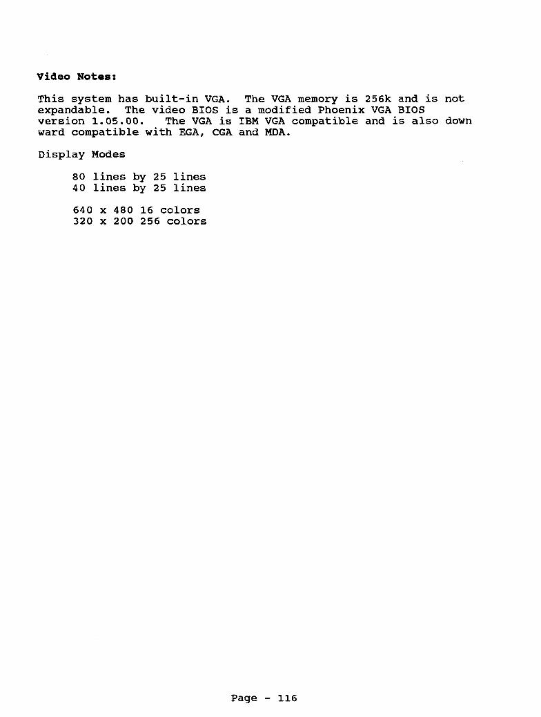
V i d e o N o t e s :
This system has built-in VGA. The VGA memory is 256k and is not expandable. The video BIOS is a modified Phoenix VGA BIOS version 1.05.00. The VGA is IBM VGA compatible and is also down ward compatible with EGA, CGA and MDA.
Display Modes
80 lines by 25 lines 40 lines by 25 lines
640 x 480 16 colors 320 x 200 256 colors
Page - 116

P r i n t e r P o r t The printer port is a DB 25 connector.
Pin 1 3 5 7 9 11 - 13 - 15 - 17 - 19 - 21 - 23 - 25 -
- - - - -
Use STROBE DATA 1 DATA 3 DATA 5 DATA 7 Busy Select Printer Fault Select In Ground Ground Ground Ground
Audio Jack 1 - Audio Sound 2 - Ground
VGA P o r t 1 2 3 4 5 6 7 8 9 10 - 11 - 12 - 13 - 14 - 15 -
- - - - - - - - -
Red Green Blue
Ground Ground Ground Ground
Ground Ground Ground Horizontal Sync Vertical Sync
Pin 2 4 6 8 10 12 14 16 18 20 22 24
Use Data 0 Data 2 Data 4 Data 6 Printer Acknowledge Paper Out Auto Feed Initialize Ground Ground Ground Ground
Joystick P o r t s 1 - Y Axis 2 - X Axis 3 - Ground
Switch fl 4 5 - +5 Volts 6 - Switch #2
-
Page - 117

Floppy Drive Port - Internal 1 - Not Connected 3 - + 5 Volts 5 - + 5 Volts 7 - + 5 Volts 9 - + 5 Volts 11 - + 5 Volts 13 - Ground 15 - Ground 17 - Ground 19 - Ground 21 - Ground 23 - Ground 25 - Ground 27 - Ground 29 - + 12 Volts 31 - + 12 Volts 33 - + 12 Volts
2 4 6 8 10 12 14 16 18 20 22 24 26 28 30 32 34
Not Connected Not Connected Not Connected Index Drive 0 Select Drive 1 Select Not Connected Motor On Direction Step Write Data Write Enable Track 0 Write Protect Read Data Disk Side Select Disk Change
NOTE: Power is supply on the floppy drive controller cable. These lines are normally ground lines.
Keyboard Connector 1 2 - Not Used 3 - Ground 4 - +5 Volts 5 - Clock 6 - Not Used
Data - PS/2 Mouse 1 - Data 2 - Not Used 3 - Ground 4 - +5 Volts 5 6 - Not Used
Clock -
Serial Port CD 1 RD 2 TD 3
4 - DTR SG 5 CTS 6
7 - RTS cs 8
9 - RI
- - - - - -
Carrier Detect Receive Data Transmit Data Data Terminal Ready Signal Ground Clear to Send Request to Send Clear To Send Ring Indicator
Power Supply Connector 1 - -12 volts 2 - +12 volts 3 4 5 - +5 volts 6 - +5 volts
Ground Ground
- -
Page - 118

Interrupts Available Interrupt Function
0 Timer Channel 0 1 Keyboard 2 Expans ion 3 Corn Port 2 4 Com Port 1 5 Hard Disk 6 Floppy Disk Controller 7 Printer Port
1/0 Port 060 OCO OEO 1EO 200 2F8 320 370 378 3B0 3D0 3F2 3F8
Address PI0 Sound Generator Math Co-Processor Tandy Sound Joystick Interface COM 2 Hard Disk Interface Secondary Floppy Controller Printer Port Monochrome Display Adapter System Video Floppy Disk Controller COM 1
DMA Usage Channel 0 Not Used Channel 1 Expansion Cards/Sound Generator Channel 2 Expansion Bus/Floppy Controller Channel 3 Expansion BusjIDE Hard Drive
Page - 119

Tandy 1000RLX-B Tandy 1000RLX-ED-B
Catalog Number 25-1452B (1OOORLX) Catalog Number 25-1453B (1000RLX-HD)
This system is basically the same as the RLX and RLX-HD. This version came with DOS 5.0 in ROM and has a newer version of Deskmate. The new version of Deskmate (3.04.03) allows you to interface the Automatic House X-10 controller to Deskmate. The joystick ports have also been changed to an 8 pin version. Also the jumper labels
CPU Type CPU Speed Math Co-proc : Standard Memory:
Total Memory : Expansion Slots: Video Output : Power Supply :
Keyboard Floppy Drive : Hard Drive Drive Bays Floppy Ctrl Ext Floppy Port:
Printer Port : Serial Port Joystick Ports : Other Ports .
DOS Version Latest BIOS ROM:
have changed on some models.-
80286 5 Mhz / 10 Mhz Switchable
512K, on motherboard (RLX) 1 Meg on motherboard (RLX-HD) 1 Meg 1 XT style, 10" long VGA 25 Watt
101 style keyboard, PS/2 connector 1 - 3.5" 1.44 Meg came standard 1 - 40 meg hard disk on RLX-HD model only 2 - 3.5" internal drive bays High Density
DB-25, built-in to motherboard
2 ports Headphone Jack Microphone PS/2 Mouse Port
DB-9
MSDOS 5.0 In ROM 02.00.00
There is a program in the ROM called RDEE.COM. determines if the Date and Time prompts should be displayed and if DOS or Deskmate should be run.
lOOORLX Motherboard
This program
Jumper Settings
E7-E8 VGA on IRQ 3, No jumper - disable (Default) VGA on IRQ 3, Jumper - Enable
Page - 120

El-E2 Floppy Controller Primary (3FO-3F7) (Default) E2-E3 Floppy Controller Secondary (370-377)
E9-ElO Disable built-in VGA E10-E11 Enable built-in VGA (Default)
E4-E5 Map Video BIOS at F0000-F7FFF and C0000-C7FFF (Default) E5-E6 Disable dual mapping of video Bios
There is another jumper setting on the small satellite board located at the top inside rear of the computer. jumper pins, with the center being common. marked and your choices are:
There are three This is how they are
E6 Microphone Input <---- + I I
E8 Line Audio Input <---- + E7 Common Pin <---- +
E12-El3 Microphone Input, allows you to connect a microphone
E13-El4 Line Audio Input, allows you to connect input from
to the computer.
line-level output from music keyboard, stereos, etc.
E15-El6 Line Output
E16-El7 Headphone Output
Main Logic Board Chips u1 - Setup EEPROM u7 - Floppy drive controller U8 - Keyboard, Mouse, Interrupt controller u10 - Clock Chip (located under U13) U13 - BIOS ROM u21 - System controller u22 - 8OL286-10 low power CPU U29 - Sound, Serial, Printer, Joystick controller
U3, U6, U11, U12 256k x 4 system RAM = 512K u2, u4, u5, u9 256K x 4 ZIP system RAM = 512k for a total
U18 and U19 Video RAM
of 1 meg RAM
Hard Type is a Seagate ST351A/X set in the XT mode.
For more information on this system, check under the RLX and RLX- HD section.
Page - 121

Tandy 1000RSX Tandy 1000RSX-HD
Catalog Number 25-1454 (1000RSX) Catalog Number 25-1455 (1000RSX-HD)
CPU Type CPU Speed Math Co-proc : Standard Memory: Total Memory : Expansion Slots: Video Output : Power Supply :
80386SX 8 Mhz / 25 Mhz Switchable 80387SX-25Mhz 1 Meg 9 Meg 1 - lott long and 1 - 7" long VGA 25 Watt
Keyboard : 101 style keyboard, PS/2 connector Floppy Drive : 1 - 3.5" 1.44 Meg came standard Hard Drive : Drive Bays : 2 - 3.5" internal drive bays Floppy Ctrl : High Density Ext Floppy Port:
1 - 40 meg hard disk on RLX-HD model only
Printer Port : DB-25, built-in to motherboard
Joystick Ports : 2 ports Other Ports : Headphone Jack
Serial Port : DB-9
: Microphone : PS/2 Mouse Port
DOS Version : MSDOS 5.0 Latest BIOS ROM: 1.10.00
This system came standard with a PS/2 mouse.
lOOORSX Motherboard
Jumper Settings
El-E2 Enable on board VGA E2-E3 Disable on board VGA
E4-E5 Jumpered, allows you to plug headphones into the EAR connection.
E8-E9 Microphone Input, allows you to connect a microphone to the computer.
E7-E8 Line Audio Input, allows you to connect input from line-level output from music keyboard, stereos, etc.
Page - 122
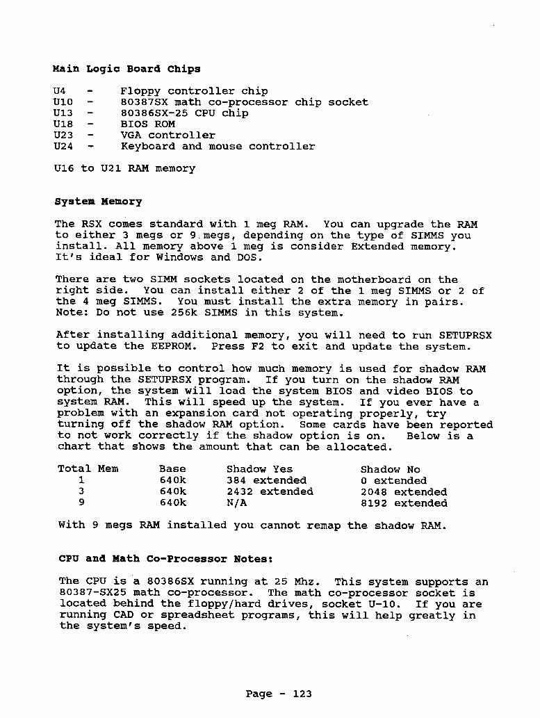
Main Logic Board Chips
u4 - Floppy controller chip u10 - 80387SX math co-processor chip socket U13 - 80386SX-25 CPU chip U18 - BIOS ROM U23 - VGA controller U24 - Keyboard and mouse controller
U16 to U21 RAM memory
System Memory
The RSX comes standard with 1 meg RAM. You can upgrade the RAM to either 3 megs or 9.megs, depending on the type of SIMMS you install. All memory above 1 meg is consider Extended memory. It's ideal for Windows and DOS.
There are two SIMM sockets located on the motherboard on the right side. You can install either 2 of the 1 meg SIMMS or 2 of the 4 meg SIMMS. You must install the extra memory in pairs. Note: Do not use 256k SIMMS in this system.
After installing additional memory, you will need to run SETUPRSX to update the EEPROM. Press F2 to exit and update the system.
It is possible to control how much memory is used for shadow RAM through the SETUPRSX program. If you turn on the shadow RAM option, the system will load the system BIOS and video BIOS to system RAM. This will speed up the system. If you ever have a problem with an expansion card not operating properly, try turning off the shadow RAM option. to not work correctly if the shadow option is on. Below is a chart that shows the amount that can be allocated.
Some cards have been reported
Total Mem Base Shadow Yes Shadow No 1 640k 384 extended 0 extended 3 640k 2 4 3 2 extended 2048 extended 9 640k N/A 8192 extended
With 9 megs RAM installed you Cannot remap the shadow RAM.
CPU and Math Co-Processor Notes:
The CPU is a 80386SX running at 25 Mhz. 80387-6x25 math co-processor. The math co-processor socket is located behind the floppy/hard drives, socket U-10. If you are running CAD or spreadsheet programs, this will help greatly in the system's speed.
This system supports an
Page - 123

100ORSX & RSX-ED 3.5" 1.44 Meg Floppy Drive
The 1.44 meg Teac FD235HF-106U (modified) or the Sony MP-F17W-00 may be used in this system.
Floppy Drive Jumper Settings
DO - Drive select 0 D1 - Drive select 1
On some models of the Teac floppy drive, the DO and D1 may be labeled as DSO and DS1. On the Sony drive, there is a slide switch on the side, near the rear of the drive, that is used for selecting the drive setting. cable.
Power is drawn from the ribbon
NOTE: This is NOT a standard 3.5" floppy drive. It has been designed to draw the power through the data cable. use a standard 3.5" floppy drive as you will short out your system.
DO NOT try to
Teac is well known for changing the part numbers on their drives. The above listed model number is for the factory supply drive. There are other models of the Teac drives that will work in the RSX and RSX-HD. These drives are a modified version of a standard 3.5" floppy drive. These modified drives have been setup to accept power through the flat ribbon data cable. Make sure when you order an A or B drive for the RSX and RSX-HD that it has the correct eject button. Some third party companies will have you cut up your computer case in order to install their drives. The proper drive will have no face plate and have a blue eject button. The RSX and RSX-HD has the floppy drive face plate built-in to the case.
Hard Drives
The RSX and RSX-HD has a built-in AT IDE interface. can use any industry standard l 1 I high, 3.5" AT IDE hard drive. This is the only system in the 1000 line that supports AT IDE drives.
This system
When you install a hard drive into this system, you will need to run SETUPRSX and enter the user defined parameters for the hard drive . The RSX-HD came standard with a 52 meg Quantum LPS52 hard drive or a Conner CP-30064 hard drive.
NOTE: Never run HSECT or AUTOFMT on these hard drives. It can render them useless.
Page - 124

The RSX Setup Program
The SETUPRSX program gives you access to the system's setup configuration. It is important to run this program when installing floppy disk drives, video options, startup boot options, configuration options, etc.
The setup program can be accessed by the SETUPRSX program on the utilities disk or by rebooting the computer and pressing F2. setup screen will then be displayed.
The
When in setup, the following keys are used:
F1 = Help F2 = Save setup information F10 = Reset to factory settings
Serial Port You can select whether the serial port is COM 1 or COM 2 in the RSX setup program.
Parallel Port You can select whether the parallel port is Uni-Directional or Bi-Directional through the RSX setup program. attaching an external floppy drive to the system, you will need to make sure the parallel port is set for Bi-Directional.
If you will be
Remap Shadow Ram This option allows you to remap 384k of system to RAM to be extended memory or to be used as shadow RAM. Remapping the 384k to shadow RAM will allow the system to run faster, by copying the system BIOS and video BIOS to RAM.
CMOS/Clock Notes
There is a 3 volt battery that holds the CMOS memory and it is used for the clock. so often. The battery is located right behind where the floppy/hard drive mounts. Radio Shack stores.
This battery will need to be replaced every
This battery can be purchased at most
Power Supply
There is a 25 watt power supply in this system. is cooled by vents rather than a cooling fan. power supply used in the 1000 RL, RLX, RLX-B and RSX.
The power supply This is the same
Keyboard Notes:
This system uses a standard PS/2 style keyboard.
Page - 125

Video Notes:
This system has built-in VGA. The VGA memory is 256k and is expandable to 512K. The video BIOS is an AcuMos AVGA2. All standard VGA, EGA, CGA and MDA video modes are supported.
Super VGA modes are supported by upgrading the video memory to 512K. The most common SVGA modes are listed below:
Super VGA Modes:
1024 x 768 16 colors 800 x 600 256 colors 640 x 480 256 colors
The video memory upgrade consists of 2 - 256 x 4 DRAM chips. They plug into the two empty sockets on the motherboard near the CMOS battery.
There are three programs on the system utilities disk that are for VGA support. They are as follows:
ACU . EXE Selects VSYNC modes AVGA2CFG.COM Run after running ACU.EXE SETMODE.EXE Selects various standard and extended video
modes.
Whenever you change the VSYNC mode with ACU.EXE, you will need to run AVGA2CFG.COM. It is best to load this file in the autoexec.bat file, that way it will load the proper VSYNC modes every time you boot.
Windows 3.1 If you wish to use Windows in one of the SVGA modes, you will need to install the drivers from the utilities disk. Run the Windows setup program and insert the system's utilities disk into drive A:. Select other under video choices. You will be asked to enter the driver, type in A:\win31.
You will have the follow choices:
1024 x 768 16 colors 800 x 600 256 colors 800 x 600 16 colors 640 x 480 256 colors
Page - 126

Printer Port The printer port is a DB
Pin Use 1 - STROBE 3 - DATA 1 5 - DATA 3 7 - DATA 5 9 - DATA 7 11 - Busy 13 - Select 15 - Printer Fault 17 - Select In 19 - Ground 21 - Ground 23 - Ground 25 - Ground
25 connector.
Pin 2 4 6 8 10 - 12 - 14 - 16 - 18 - 20 - 22 - 24 -
- - - -
Use Data 0 Data 2 Data 4 Data 6 Printer Acknowledge Paper Out Auto Feed Initialize Ground Ground Ground Ground
Audio Jack Power Supply Audio Sound 1 -12 Volts 1
2
VGA 1 2 3 4 5 6 7 8 9 10 11 12 13 14 15
Ground
Red Green Blue
Ground Ground Ground Ground
Ground Ground Ground Horizontal Sync Vertical Sync
2 - +12 Volts 3 - Ground
Ground 4 5 - + 5 Volts 6 - + 5 Volts
-
Page - 127

Floppy Drive Port - Internal 1 - Not Connected 3 - + 5 Volts 5 - + 5 Volts 7 - + 5 Volts 9 - + 5 Volts 11 - + 5 Volts 13 - Ground 15 - Ground 17 - Ground 19 - Ground 21 - Ground 23 - Ground 25 - Ground 27 - Ground 29 - + 12 Volts 31 - + 12 Volts 33 - + 12 Volts
2 4 6 8 10 12 14 16 18 20 22 24 26 28 30 32 34
Not Connected Not Connected Not Connected Index Drive 0 Select Drive 1 Select Not Connected Motor On Direction Step Write Data Write Enable Track 0 Write Protect Read Data Disk Side Select Disk Chanqe
NOTE: These lines are normally ground lines.
Power is supply on the floppy drive controiler cable.
Keyboard Connector 1 - Data 2 - Not Used 3 4 - +5 Volts 5 - Clock 6 - Not Used
Ground -
PS/2 Mouse 1 - Data 2 - Not Used 3 - Ground
+5 Volts 4 5 - Clock
Not Used 6
- -
Serial Port 1 - CD Carrier Detect 2 - RD Receive Data 3 - TD Transmit Data 4 - DTR Data Terminal Ready 5 - SG Signal Ground 6 - CTS Clear to Send 7 - RTS Request to Send 8 - CS Clear To Send 9 - RI Ring Indicator
Page - 128

Interrupts Available IRQ 0 System IRQ 1 Keyboard IRQ 2 Route to interrupts 8 to 15 IRQ 3 COM 2 / COM 4 IRQ 4 COM 1 / COM 3 IRQ 5 Printer LPT 2 IRQ 6 Floppy Drives IRQ 7 Printer LPT 1
IRQ 8 Real Time Clock IRQ 9 Reserved IRQ 10 Available IRQ 11 Available IRQ 12 Available IRQ 13 Math Co-processor IRQ 14 Hard Drive Controller IRQ 15 2nd Hard Drive Controller
1/0 Port Address 060 PI0 OCO Sound Generator OEO Math Co-Processor 1EO Tandy Sound 200 Joystick Interface 2F8 COM 2 320 Hard Disk Interface 370 Secondary Floppy Controller 378 Printer Port 3B0 Monochrome Display Adapter 3D0 System Video 3F2 Floppy Disk Controller 3F8 COM 1
DMA Usage Channel 0 N o t Used Channel 1 Expansion Cards/Sound Generator Channel 2 Expansion Bus/Floppy Controller Channel 3 Expansion Bus/IDE Hard Drive
Page - 129

Tandy 1OOOSL
Catalog Number 25-1401
CPU Type CPU Speed Math Co-proc : Standard Memory: Total Memory : Video Memory : Expansion Slots: Video Output : Power Supply :
Keyboard Floppy Drive : Hard Drive Drive Bays Floppy Ctrl
Printer Port : Serial Port Joystick Ports : Other Ports
DOS Version Latest BIOS ROM:
8086 4.77 Mhz / 8 Mhz Switchable 8087 8 Mhz 384K, on motherboard 640k, expandable on motherboard
5 - 8bit expansion slots lov1 long CGA, Monochrome, TGA 67 Watt
N/A
101 Style Keyboard 1 - 5.25" 360K came standard 2 - 5.25" internal drive bays Low density
34 Pin card edge, built-in to motherboard 9 pin 2 ports, 6 pin din connector Headphone Jack Microphone
MSDOS 3.3 In ROM 01.04.00
lOOOSL Motherboard
On the satellite audio board:
El-E2 Microphone Input, allows you to connect a microphone to the computer.
E2-E3 Line Audio Input, allow you to connect input from line- level output from music keyboard, stereos, etc
On the motherboard:
E2-E3 (Default) Sets IRQ 5 for the hard drive and IRQ 2 for the video.
E3 -E4 Sets IRQ 2 fur the hard drive and IRQ 5 for the video. It is really not recommended to use this setting. Not all software will run correctly on IRQ2.
E5-E6 Connects SLCTIN to the printer E6-E7 Ties SLCTIN high (standard may be jumpered or not)
Page - 130

System Memory
The lOOOSL came standard with 384K of memory on the motherboard. This is upgradeable to 640k by adding an additional 256K of memory. You will need 8 - 64 x 4 DRAM chips (DO NOT try to use 256k chips). Simply plug the 8 chips into the 8 empty sockets on the motherboard. There are no jumpers or switches to change.
CPU and Math Co-Processor Notes:
The CPU is an 8086 processor. with a V-30 processor for improved performance.
You can replace this processor
The math co-processor is installed in the empty socket located at U21 on the motherboard.
lOOOSL Teac 360K FD55 Floppy Disk Drive
This is a standard Teac 360K floppy drive. handled by changing the drive select jumper on the drive. through the flat ribbon cable, as it is done on many compatibles.
On the floppy drive, at the rear of the drive, on the bottom side, you will find a row of jumpers labeled DO, D1, D2 and D3. These are the drive select jumpers.
Drive selection is Not
DO = Drive A D1 = Drive B
The floppy drive cable is not very long. floppy drive, you may need a longer floppy drive cable.
If you install a 3.5Il
NOTE: Power is supplied through the flat ribbon cable. Even though the 360K floppy drive does not use it. BE CAREFUL when using a different floppy drive cable. cable in the system now, you will notice that there are some holes punched in the cable. through the cable.
Look at the floppy drive
This prevents the power from going
Hard Drives
This system'can handle either a hard card or hard drive. There are only two drive bays. that you don't loose the 2nd drive bay.
Note: A hard card is recommended so
The SL Setup Program
This computer has part of MSDOS 3.3 built-in to the ROM. allows you to simply turn on the computer and boot to a DOS
This
Page - 131

prompt without having to insert a floppy disk into drive A. contained in ROM is Deskmate. support programs are in the ROM. The rest of Deskmate is on diskettes.
Also The main desktop menu and some
NOTE: SETUPSL /A option will give you additional setup information for video memory size, certain chip selects, network options, etc. Be careful when running the /A option.
Tech Note: You can change the video mode from monochrome and color by using the following key sequence during bootup:
This means you would hold down the CTRL key, then hold down the ALT key, then hold down the SHIFT key and then press the V key, while keeping other keys held down.
There is also an EEPROM in the system that contains such information as type of video display, prompt for date and time, number of disk drives, etc. drive you must run the SETUPSL to update the system configuration.
Whenever you add or remove a disk
If you are running a program that requires the use of a config.sys file or autoexec.bat file and you are booting from ROM, then make the following changes in the SETUPSL program.
Check For Config.sys On Drive A or C Check For Autoexec.bat On Drive A or C
Using A Higher Version DOS
Yes, you can use DOS 5.0 or 6.0 or higher on the SL. All you will need to do is boot the system with the old version DOS and run the SETUPSL program. Set the system for:
Primary Start-up Device DISK Initial Start-up Program MS-DOS
Save the setup and reboot the system.
From now on, the computer will boot from a higher version DOS disk, when placed in drive A or from a hard disk.
Clock Chip Notes
The smartwatch or clock chip option is installed in the special Smartwatch 28 pin socket on the motherboard at location U13. See the chart on clock chips for more information about the software.
Page - 132

serial Ports
This system has a 9 pin serial port located on the back of the computer.
Keyboard N o t e s :
This system uses a standard 101 style keyboard set in the XT mode. NOTE: Not all 101 style keyboards can be set into the XT mode. only has 5 pins.
The original keyboard has 7 pins and a standard keyboard The 5 pin keyboard will still work.
V i d e o N o t e s :
This system supports Hercules Graphics (monochrome) and standard CGA along with an extended CGA mode. This is also referred to as TGA. Standard CGA will allow it to display 4 colors, whereas the TGA mode will allow you to display up to 16 colors.
The SL only has one video connection on the back of the computer. You can connect either a CGA or Mono monitor to the video port. You will need to change the mode of the video port when changing from CGA to Mono or Mono to CGA. CTRL + ALT + SHIFT + V all at the same time. This will cause the video mode to switch and the system to reboot.
This can be done by pressing
Display Modes
80 lines by 25 lines 40 lines by 25 lines
16 foreground colors / 8 background colors
Graphics Modes
Colors Resolution 4 320 x 200 16 320 x 200 16 160 x 200 2 640 x 200 4 640 x 200 16 640 x 200
Mono 720 x 348 Hercules Graphics Mode
VGA: This system can run VGA. You will need a VGA card that is able to run in an 8 bit mode. the CMll or CM5 are not VGA monitors.
You will also need a VGA monitor,
Page - 133

Printer Port The printer port is a 34 pin card edge.
Pin 1 3 5 7 9 11 13 15 17 19 21 23 25 27 29 31 33
Use STROBE DATA 0 DATA 1 DATA 2 DATA 3 DATA 4 DATA 5 DATA 6 DATA 7 Printer ACK BUSY Out of Paper Select Auto Feed Not Connected Ground Ground
Audio Jack 1 - Ground 2 - Audio Out
RGB Port (CGA Video) 1 - Ground 2 - Ground 3 - RED 4 - Green 5 - Blue 6 - Intensity 7 - Green - Mono 8 - Horizontal Sync 9 - Vertical Sync
Pin 2 4 6 8 10 12 14 16 18 20 22 24 26 28 30 32 34
Use Ground Ground Ground Ground Ground Ground Ground Ground Ground Ground Ground Ground Not Connected Printer Fault Printer Init Not Connected + 5 volts
Joystick Ports
Keyboard 1 2 3 4 5 6 7
- - - - - - -
Y Axis X Axis Ground Switch #1 +5 Volts Switch #2
Clock Data Reset Ground + 5 volts Busy Type
Page - 134

Floppy Drive Port - Internal 1 - Not Connected 3 - + 5 Volts 5 - + 5 Volts 7 - + 5 Volts 9 - + 5 Volts 11 - + 5 Volts 13 - Ground 15 - Ground 17 - Ground 19 - Ground 21 - Ground 23 - Ground 25 - Ground 27 - Ground 29 - + 12 Volts 31 - + 12 Volts 33 - + 12 Volts
2 4 6 8 10 12 14 16 18 20 22 24 26 28 30 32 34
Not Connected Not Connected Not Connected Index Drive 0 Select Drive 1 Select Drive 2.Select Motor On Direction Step Write Data Write Enable Track 0 Write Protect Read Data Disk Side Select Disk Change
NOTE: These lines are normally ground lines.
Power is supply on the floppy drive controller cable.
Serial Port
CD RD TD DTR SG CTS RTS cs RI
Interrupts Interrupt
0 1 2 3 4 5 6 7
Carrier Detect Receive Data Transmit Data Data Terminal Ready Signal Ground Clear to Send Request to Send Clear To Send Ring Indicator
Available Function Timer Channel 0 Keyboard Video Com Port 2 Corn Port 1 Hard Disk Floppy Disk Controller Printer Port
Page - 135

1/0 Port Address 060 PI0 OCO Sound Generator OEO Math Co-Processor 1EO Tandy Sound 200 Joystick Interface 2F8 COM 2 320 Hard Disk Interface 370 Secondary Floppy Controller 378 Printer Port 3B0 Monochrome Display Adapter 3D0 System Video 3F2 Floppy Disk Controller 3F8 COM 1
Page - 136

Tandy 1000SL/2
Catalog Number 25-1402
CPU Type CPU Speed Math Co-proc : Standard Memory: Total Memory : Video Memory : Expansion Slots: Video Output : Power Supply :
Keyboard Floppy Drive : Hard Drive Drive Bays
Floppy Ctrl
Printer Port : Serial Port Joystick Ports : Other Ports
DOS Version Latest BIOS ROM:
8086 4.77 Mhz / 8 Mhz Switchable 8087 8 Mhz 512K, on motherboard 640k, expandable on motherboard
5 - 8bit expansion slots lot1 long CGA, TGA 67 Watt
N/A
101 Style Keyboard 1 - 3.5" 720K came standard
1 - 5.25" internal drive bay 1 - 3.5" internal drive bay Low density
34 Pin card edge, built-in to motherboard 9 pin 2 ports, 6 pin din connector Headphone Jack Microphone
MSDOS 3.3 In ROM 01.04.04
There are two main motherboard revisions. Revision C and D. Revision D has the same jumper setting as Revision C. difference is that is has a jumper setting E901-E902-E903. Jumpering E901-E902 sets the system to use the Sharp ROM set 8079047 and 8079048. The jumper setting E902-E903 is for all other ROM sets.
Its main
1000SL/2 Motherboard
On the satellite audio board:
E2-E3 Microphone Input, allows you to connect a microphone to the computer.
El-E2 Line Audio Input, allow you to connect input from line- level output from music keyboard, stereos, etc
On the motherboard:
E2-E3 (Default) Sets IRQ 5 for the hard drive and IRQ 2 for
E3-E4 Sets IRQ 2 for the hard drive and IRQ 5 for the video. Not
the video.
It is really not recommended to use this setting.
Page - 137

all software will run correctly on IRQ2. E5-E6 Connects SLCTIN to the printer E6-E7 Ties SLCTIN high (standard may be jumpered or not)
System Memory
The 1000SL/2 came standard with 512K of memory on the motherboard. This is upgradeable to 640k by adding an additional 128K of memory. You will need 4 - 64 x 4 DRAM chips (DO NOT try to use 256k chips). Simply plug the 4 chips into the 4 empty sockets on the motherboard. There are no jumpers or switches to change.
System Memory Map
Address Description 00000-7FFFF 512K system RAM 80000-9FFFF A0000-BFFFF 128K video RAM C0000-DFFFF 128k expansion memory, above board E0000-FFFFF 128k system BIOS
128K system and video RAM
The video in this system will use 16k to 64k of system RAM, depending on the video mode. This will reduce the amount of memory you have for your programs.
CPU and Math Co-Processor Notes:
The CPU is an 8086 processor. with a V-30 processor for improved performance.
You can replace this processor
The math co-processor is installed in the empty socket located next to the CPU chip at location U21.
1000SL/2 720K Teac or Sony Floppy Drive
This is not a standard 720K floppy drive, power is supplied through the flat ribbon cable. Drive selection is handled by changing the drive select jumper on the drive. flat ribbon cable, as it is done on many compatibles.
Not through the
Floppy Drive Jumper Settings
DO - Drive select 0 D1 - Drive select 1
On some models of the Teac floppy drive, the DO and D1 may be labeled as DSO and DS1. On the Sony drive, there is a slide switch on the side, near the rear of the drive, that is used for selecting the drive setting. Power is drawn from the ribbon cable.
Page - 138

NOTE: This is NOT a standard 3.5" floppy drive. It has been designed to draw the power through the data cable. use a standard 3.5Ig floppy drive, as you will short out your system.
DO NOT try to
Hard Drives
This system can handle either a hard card or hard drive. Note: There are only two drive bays. A hard card is recommended so that you don't loose the 2nd drive bay.
The SL/2 Setup Program
This computer has part of MSDOS 3 . 3 built-in to the ROM. This allows you to simply turn on the computer and boot to a DOS prompt without having to insert a floppy disk into drive A. contained in ROM is Deskmate. support programs are in the ROM. The rest of Deskmate is on diskettes.
Also The main desktop menu and some
NOTE: SETUPSL2 /A option will give you additional setup information for video memory size, certain chip selects, network options, etc. Be careful when running the /A option.
Tech Note: You can change the video mode from monochrome and color by using the following key sequence during bootup:
<CTRL><ALT><SHIFT><V>
This means you would hold down the CTRL key, then hold down the ALT key, then hold down the SHIFT key and then press the V key, while keeping other keys held down.
There is also an EEPROM in the system that contains such information as type of video display, prompt for date and time, number of disk drives, etc. drive you must run the SETUPSL2 to update the system configuration.
Whenever you add or remove a disk
If you are running a program that requires the use of a config.sys file or autoexec.bat file and you are booting from ROM, then make the following changes in the SETUPSL2 program.
Check For Config.sys On Drive A or C Check For Autoexec.bat On Drive A or C
Page - 139

Using A Higher Version DO8 Yes, you can use DOS 5.0 or 6.0 or higher on the SL2. All you will need to do is boot the system with the old version DOS and run the SETUPSL program. Set the system for:
Primary Start-up Device DISK Initial Start-up Program MS-DOS
Save the setup and reboot the system.
From now on, the computer will boot from a higher version DOS disk, when placed in drive A or from a hard disk.
Clock Chip Notes The smartwatch or clock chip option is installed in the special Smartwatch 28 pin socket on the motherboard at location U13.
Serial Ports This system has a 9 pin serial port located on the back of the computer.
Keyboard Notes: This system uses a standard 101 style keyboard set in the XT mode. NOTE: Not all 101 style keyboard can be set into the XT mode. The original keyboard has 7 pins and a standard keyboard only has 5 pins. The 5 pin keyboard will still work.
Video Notes: This system supports Hercules Graphics (monochrome) and standard CGA along with an extended CGA mode. This is also referred to as TGA. Standard CGA will allow you to display 4 colors, where as the TGA mode will allow you to display up to 16 colors.
The SL/2 only has one video connection on the back of the computer. You can connect either a CGA or Mono monitor to the video port. when changing from CGA to Mono or Mono to CGA. This can be done by pressing CTRL + ALT + SHIFT + V all at the same time. This will cause the video mode to switch and the system to reboot.
You will need to change the mode of the video port
Page - 140

Display Modes
80 lines by 25 lines 40 lines by 25 lines 16 foreground colors / 8 background colors
Graphics Modes
Colors 4 16 16 2 4 16
Mono
Resolution 320 x 200 320 x 200 160 x 200 640 x 200 640 x 200 640 x 200 720 x 348 Hercules Graphics Mode
VGA: This system can run VGA. You will need a VGA card that is able to run in an 8 bit mode. You will also need a VGA monitor, the CMll or CM5 are not VGA monitors.
Page - 141

Printer Port The printer port is a 34 pin card edge.
Pin 1 3 5 7 9 11 13 15 17 19 21 23 25 27 29 31 33
Use STROBE DATA 0 DATA 1 DATA 2 DATA 3 DATA 4 DATA 5 DATA 6 DATA 7 Printer ACK BUSY Out of Paper Select Auto Feed Not Connected Ground Ground
Audio Jack 1 - Ground 2 - Audio Out
(CGA Video) Ground Ground RED Green Blue Intensity Green - Mono Horizontal Sync Vertical Sync
Pin 2 4 6 8 10 12 14 16 18 20 22 24 26 28 30 32 34
Use Ground Ground Ground .Ground Ground Ground Ground Ground Ground Ground Ground Ground Not Connected Printer Fault Printer Init Not Connected + 5 volts
Joystick Ports 1 - Y Axis 2 - X Axis 3 - Ground 4 - Switch #1 5 - +5 Volts 6 - Switch #2
Keyboard Clock 1
2 - Data 3 - Reset 4 - Ground 5 - + 5 volts 6 - Busy 7
-
Type -
Page - 142

Floppy Drive Port - Internal 1 - Not Connected 3 - + 5 Volts 5 - + 5 Volts 7 - + 5 Volts 9 - + 5 Volts 11 - + 5 Volts 13 - Ground 15 - Ground 17 - Ground 19 - Ground 21 - Ground 23 - Ground 25 - Ground 27 - Ground 29 - + 12 Volts 31 - + 12 Volts 33 - + 12 Volts
2 4 6 8 10
14 16 18 20 22 24 26 28 30 32 34
12
Not Connected Not Connected Not Connected Index Drive 0 Select Drive 1 Select Drive 2 Select Motor On Direction Step Write Data Write Enable Track 0 Write Protect Read Data Disk Side Select Disk Change
NOTE: These lines are normally ground lines.
Power is supply on the floppy drive controller cable.
Serial Port 1 - CD Carrier Detect 5 2 - RD Receive Data 6 3 - TD Transmit Data 7 4 - DTR Data Terminal Rdy 8 -
9
SG CTS RTS cs RI
- - - -
Interrupts Available Interrupt Function
0 Timer Channel 0 1 Keyboard 2 Video 3 Com Port 2 4 Corn Port 1 5 Hard Disk 6 Floppy Disk Controller 7 Printer Port
1/0 Port Address 060 PI0 OCO Sound Generator OEO Math Co-Processor 1EO Tandy Sound 200 Joystick Interface 2F8 COM 2 320 Hard Disk Interface 370 Secondary Floppy Controller 378 Printer Port 3B0 Monochrome Display Adapter 3D0 System Video 3F2 . Floppy Disk Controller 3F8 COM 1
Signal Ground Clear to Send Request to Send Clear to Send Ring Indicator
Page - 143

Tandy 10008X
Catalog Number 25-1051
CPU Type CPU Speed Math Co-proc : Standard Memory: Total Memory : Video Memory : Expansion Slots: Video Output : Power Supply :
Keyboard Floppy Drive : Hard Drive Drive Bays Floppy Ctrl
8088 4 . 7 7 / 7 . 1 6 Mhz Selectable 8087 384K, on motherboard 640k, expandable on motherboard
5 - 8 bit XT slots ( l o m m long) CGA & Composite Monochrome 67 Watt
N/A
Tandy style 90 keys 1 - 5 1 / 4 " 360K came standard
2 - 5 1 / 4 " drive bays Low density
Printer Port : 34 Pin card edge, built-in to motherboard Serial Port : N/A Joystick Ports : 2 ports, 6 pin din connector Other Ports : Light Pen Port - DB 9
: Composite Video - RCA connector : Audio Output - RCA connector
DOS Version : MSDOS 3 . 2 Latest BIOS ROM: 0 1 . 0 2 . 0 0
100OSX Motherboard Jumpers
El-E2 Jumpered if only 384k memory is installed Removed, when you install the 256K memory upgrade kit
E3-E4 Jumpered if there is NO math co-processor Removed, when you install a math co-processor
E6-E7 Jumpered connects printer select to parallel port
Note: E6-E7 should be removed to use of some IBM software and/or IBM compatible printers. programs that use the status line for printer control.
This may be necessary for some IBM
DIP Switch Setting
1 - OFF Selects composite monochrome monitor ON Selects CGA monitor (Default)
2 - OFF Selects IRQ 5 for hard drive/IRQ 2 for video ON Selects IRQ 2 for hard drive/IRQ 5 for video
(default)
Page - 144

3 - OFF Disables IRQ 6 , floppy controller IRQ ON Enables IRQ6, (default)
4 - OFF Disables IRQ 7 , printer port IRQ ON Enables IRQ 7, (default)
NOTE: For some hard drives and hard cards, you will need to set switch 2 to OFF. This allows you to use standard XT controller cards in the SX.
Memory
The 384k of memory on the motherboard consists of 8 - 256 x 1 chips and 4 - 64 x 4 chips.
To upgrade the SX to 640R, you will need to install 8 - 256K x 1 DRAM chips into the eight empty sockets on the motherboard. Then remove jumper E l - E 2 .
CPU and Math Co-Processor Notes:
The CPU is an 8088 processor. You can replace this processor with a V-20 processor for improved performance.
The math co-processor is installed in the empty socket located at U33. Once you have installed the math co-processor you must remove the jumper at E3-E4.
1OOOSX Teac 360K FD55BV Floppy Disk Drive
This is a standard Teac 360K floppy drive. Drive selection is handled by changing the drive select jumper on the drive. Not through the flat ribbon cable, as it is done on many compatibles.
On the floppy drive, at the rear of the drive, on the bottom side, you will find a row of jumpers labeled DO, D1, D2 and D 3 . These are the drive select jumpers.
DO = Drive A D1 = Drive B
The floppy drive cable is not very long. floppy drive, you may need a longer floppy drive cable.
If you install a 3.5'l
Note: The on-board floppy controller will support a 720K floppy drive as A: or B:. add a drivparm or driver.sys statement to you config.sys file. More information on installing a 5 1/411 floppy drive may be found on the Itsecrets of the 1000'~~~ video.
Depending on the DOS version you may need to
Page - 145

3.5" 720K Floppy D r i v e s
You can add a 3.511 720K floppy need:
3.5" Floppy Drive 5 1/4" Mounting Frame MSDOS 3.2 or Higher Longer Floppy Drive Cable
You will need to configure the drive B: by changing the drive the 5 1/4" drives.
drive to your system. You will
(optional, but helpful)
drive to be either drive A: or select jumpers, like above with
You will also need to add one of the two following lines to your config.sys file.
drivparm=/D:O <-- if the 3.5" drive is drive A:
drivparm=/D:l <-- if the 3.5" drive is drive B:
The drivparm command will inform MSDOS that the A: drive is a 720K floppy drive. If you don't add this line, the system will think that it is only a 360k floppy.
NOTE: into this system.
It is possible to install a 1.2 or 1.44 meg floppy drive See the section on High Density Floppy Drives.
H a r d D r i v e s
This system can handle either a hard card or hard drive. Note: There are only two drive bays. A hard card is recommended so that you don't loose the 2nd drive bay.
This system can use a standard Seagate STllM (for MFM) or STllR (for RLL) controller, when you set DIP switch 2 off. You can also run an IDE drive in this system with the proper IDE controller.
Serial Ports
This system does not have a built-in serial port, added. system as a serial port.
one can be Do not try to use the light pen port on the back of the
It is not electrically the same.
Clock N o t e s :
A @@Smartt1 clock chip can be installed into this system. chart for clock chips for the exact location and software information.
See the
Page - 146

Keyboard Notes:
The lOOOSX does not use a standard keyboard interface. It is possible to connect a 101 style keyboard to these 1000fs. You will either need a special keyboard converter Tandy part number 25-1030 (has been discontinued for awhile) or a keyboard with the converter built-in. Tandy produced a keyboard, model 25-4038 had a converter built-in.
There are also a couple of third party manufacturers that have made keyboards for the 1000fs, they are Datadesk and Northgate. When connecting up the Northgate keyboard, you will need to change the DIP switch setting found under the name plate.
Video Notes:
This system supports composite monochrome and standard CGA along with an extended CGA mode. This is also referred to as TGA. Standard CGA will allow you to display 4 colors, where as the TGA mode will allow you to display up to 16 colors. Very similar to EGA, but without the higher resolution. When connecting a composite monochrome monitor, you should turn DIP switch 1 OFF on the motherboard.
Display Modes
80 lines by 25 lines 40 lines by 25 lines
16 foreground colors / 8 background colors
Graphics Modes
Colors Resolution 4 320 x 200 16 320 x 200 16 160 x 200 2 640 x 200 4 640 x 200
VGA: This system can use VGA, however, an expansion slot will be needed. The VGA card must be able to run in an 8 bit mode. You will also need a VGA monitor, the CMll or CM5 are not VGA monitors.
Page - 147
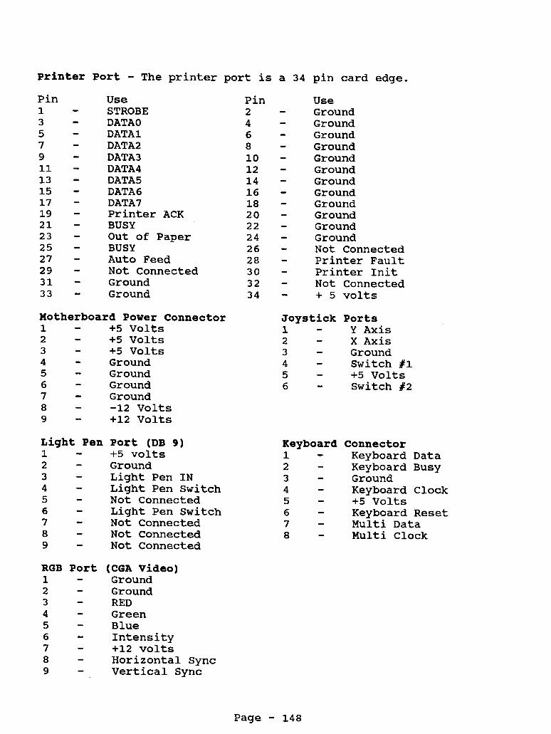
Printer Port - The printer port is Pin 1 3 5 7 9 11 - 13 - 15 - 17 - 19 - 21 - 23 - 25 - 27 - 29 - 31 - 33 -
- - - - -
Use STROBE DATA0 DATA1 DATA2 DATA3 DATA4 DATA5 DATA6 DATA7 Printer ACK BUSY Out of Paper BUSY Auto Feed Not Connected Ground Ground
Motherboard Power Connector 1 - +5 Volts 2 - +5 Volts 3 - +5 Volts 4 - Ground 5 - Ground 6 - Ground 7 - Ground 8 - -12 Volts 9 - +12 Volts
Port (DB 9) +5 volts Ground Light Pen IN Light Pen Switch Not Connected Light Pen Switch Not Connected Not Connected Not Connected
RGB Port (CGA Video) 1 - Ground 2 - Ground 3 4 - Green 5 - Blue 6 - Intensity 7 - +12 volts 8 - Horizontal Sync 9 - Vertical Sync
RED -
Pin 2 4 6 8 10 12 14 16 18 20 22 24 26 28 30 32 34
a 34 pin card edge.
Use Ground Ground Ground Ground Ground Ground Ground Ground Ground Ground Ground Ground Not Connected Printer Fault Printer Init Not Connected + 5 volts
Joystick Ports 1 - Y Axis 2 - X Axis
Ground 3 Switch #1 4 +5 Volts 5 Switch #2 6
- - - -
Keyboard 1 2 3 4 5 6 7 8
- - - - - - - -
Connector Keyboard Data Keyboard Busy Ground Keyboard Clock +5 Volts Keyboard Reset Multi Data Multi Clock
Page - 148

Floppy Drive Port 1 - Ground 3 - Ground 5 - Ground 7 - Ground 9 - Ground 11 - Ground 13 - Ground 15 - Ground 17 - Ground 19 - Ground 21 - Ground 23 - Ground 25 - Ground 27 - Ground 29 - Ground 31 - Ground 33 - Ground
2 4 6 8 10 12 14 16 18 20 22 24 26 28 30 32 34
Interrupts Available Interrupt Function
0 Timer Channel 0 1 Keyboard
1/0 Port 060 OCO OEO 1EO 200 2F8 320 370 378 3B0 3D0 3F2
See Switch Setting Notes Com Port 2 Corn Port 1 See Switch Setting Notes Floppy Disk Controller Printer Port
Address PI0 Sound Generator Math Co-Processor Tandy Sound Joystick Interface COM 2 Hard Disk Interface Secondary Floppy Controller Printer Port Monochrome Display Adapter System Video Floppy Disk Controller
Not Connected Not Connected Not Connected Index Drive 0 Select Drive 1 Select Not Connected Motor On Direction Step Write Data Write Enable Track 0 Write Protect Read Data Disk Side Select Drive Ready/Disk Change
Page - 149

Tandy lOOOTL
Catalog Number 25-1201
CPU Type CPU Speed Math Co-proc : Standard Memory: Total Memory : Video Memory : Expansion Slots: Video Output : Power Supply :
Keyboard Floppy Drive : Hard Drive Drive Bays
Floppy Ctrl
Printer Port : Serial Port Joystick Ports : Other Ports
DOS Version Latest BIOS ROM:
80286 4.77 Mhz / 8 Mhz Switchable 80287 8 Mhz 640K, on motherboard 768k, expandable on motherboard
5 - 8bit expansion slots loll long CGA, TGA, Monochrome 67 Watt
N/A
101 Style Keyboard 1 - 3.5" 720K came standard 1 - 5.25l' internal drive bay 2 - 3.5" internal drive bay Low density
34 Pin card edge, built-in to motherboard 9 pin 2 ports, 6 pin din connector Headphone Jack Microphone
lOOOTL Motherboard
MSDOS 3.3 In ROM 01.04.02
El-E2
E2-E3
E4-E5
E6-E7
E7-E8 line-
E9-ElO
Sets IRQ 5 for the video. It is really not recommended to use this setting. Not all software will run correctly on IRQ 5.
(Default) Sets IRQ 5 for the hard drive and IRQ 2 for the video.
Jumper on connects SLCTIN to the printer Jumper off ties SLCTIN high
Microphone Input, allows you to connect a microphone to the corlputer.
Line Audio Input, allows you to connect input from level output from music keyboard, stereos, etc
Solder pads on the mother board, not used.
Page - 150

System Memory
The lOOOTL came standard with 640K of memory on the motherboard. This is upgradeable to 768k by adding an additional 128K of memory. You will need 4 - 64 x 4 DRAM chips (DO NOT try to use 256k chips). Simply plug the 4 chips into the 4 empty sockets on the motherboard. This extra memory is used for video RAM. memory, the video will use 16k to 64k of memory, depending on the video mode, from the lower 640k RAM. out of memory with some programs. you install this extra 128K. The cost is minimal.
There are no jumpers or switches to change. Without this extra
This may cause you to run It is highly recommended that
CPU and Math Co-Processor
The TL has an 80286 CPU running in the real mode. You can change the CPU out for a 386 module or 486 module by Improve. information see the chart on Speed Upgrades.
For more
The TL uses a 80287 math co-processor. The socket is located at U60 on the motherboard. There are no jumpers or switches to set. Just plug it in.
lOOOTL 720K Teac or Sony Floppy Drive
Whenever you add or remove a floppy drive from the system you will need to run the SETUPTL program.
This is not a standard 720K floppy drive, power is supplied through the flat ribbon cable. changing the drive select jumper on the drive. flat ribbon cable, as it is done on many compatibles.
Drive selection is handled by Not through the
Floppy Drive Jumper Settings
DO - Drive select 0 D1 - Drive select 1 D2 - Drive select 2
On some models of the Teac floppy drive, the D0,Dl and D2 may be labeled as DSO, DS1 and DS2. On the Sony drive, there is a slide switch on the side, near the rear of the drive, that is used for selecting the drive setting. cable.
Power is drawn from the ribbon
NOTE: This is NOT a standard 3.5" floppy drive. It has been designed to draw the power through the data cable. use a standard 3.511 floppy drive as you will short out your system. the punched holes in the flat ribbon cable. standard floppy drive cable in this system.
DO NOT try to
The power is blocked from going to the 5 1/4" drive by DO NOT try to use a
Page - 151

This system supports up to 3 floppy drives. set for a different drive selection.
Each drive must be
Hard Drives
This system can use a standard Seagate STllM (for MFM) or STllR (for RLL) controller. You can also run an IDE drive in this system with the proper IDE controller.
The TL Setup Program
This computer has part of MSDOS 3 . 3 built-in to the ROM. This allows you to simply turn on the computer and boot to a DOS prompt without having to insert a floppy disk into drive A. contained in ROM is Deskmate. support programs are in the ROM. The rest of Deskmate is on diskettes.
Also The main desktop menu and some
In the setup program you can also change which drive is designated as drive A.
NOTE: SETUPTL /A option will give you additional setup information for video memory size, certain chip selects, network options, etc. Be careful when running the /A option.
Tech Note: You can change the video mode from monochrome and color by using the following key sequence during bootup:
<CTRL><ALT><SHIFT><V>
This means you would hold down the CTRL key, then hold down the ALT key, then hold down the SHIFT key and then press the V key, while keeping other keys held down.
There is also an EEPROM in the system that contains such information as type of video display, prompt for date and time, number of disk drives, etc. drive you must run the SETUPTL to update the system configuration.
Whenever you add or remove a disk
If you are running a program that requires the use of a config.sys file or autoexec.bat file and you are booting from ROM, then make the following changes in the SETUPTL
Check For Config.sys On Drive A or C Check For Autoexec.bat On Drive A or C
Page - 152

Using A Higher Version DOS
Yes, you can use DOS 5.0 or 6.0 or higher on the TL. All you will need to do is boot the system with the old version DOS and run the SETUPTL program. Set the system for:
Primary Start-up Device DISK Initial Start-up Program MS-DOS
Save the setup and reboot the system.
From now on, the computer will boot from a higher version DOS disk, when placed in drive A or from a hard disk.
TL Battery
The TL has a 3 volt battery on the motherboard for the clock. This battery is obtained at any Radio Shack store.
Serial Ports
This system has a 9 pin serial port located on the back of the computer.
Keyboard Notes:
This system uses a standard 101 style keyboard set in the XT mode. NOTE: Not all 101 style keyboards can be set into the XT mode. The original keyboard has 7 pins and a standard keyboard only has 5 pins. The 5 pin keyboard will still work.
Video Notes:
This system supports Hercules Graphics (monochrome) and standard CGA along with an extended CGA mode. This is also referred to as TGA. Standard CGA will allow you to display 4 colors, whereas the TGA mode will allow you to display up to 16 colors.
The TL only has one video connection on the back of the computer. You can connect either a CGA or Mono monitor to the video port. You will need to change the mode of the video port when changing from CGA to Mono or Mono to CGA. This can be done by pressing CTRL + ALT + SHIFT + V all at the same time. This will cause the video mode to switch and the system to reboot.
Page - 153

Display Modes
80 lines by 25 lines 40 lines by 25 lines
16 foreground colors / 8 background colors
Graphics Modes
Colors 4 16 16 2 4 16
Mono
Resolution 320 x 200 320 x 200 160 x 200 640 x 200 640 x 200 640 x 200 720 x 348 Hercules Graphics Mode
VGA: This system can run VGA. You will need a VGA card that is able to run in an 8 bit mode. the CMll or CM5 are not VGA monitors.
You will also need a VGA monitor,
Page - 154

P r i n t e r Port The printer port is a 34 pin card edge.
Pin 1 3 5 7 9 11 13 15 17 19 21 23 25 27 29 31 33
Use STROBE DATA 0 DATA 1 DATA 2 DATA 3 DATA 4 DATA 5 DATA 6 DATA 7 Printer ACK BUSY Out of Paper Select Auto Feed Not Connected Ground Ground
A u d i o Jack 1 - Ground 2 - Audio Out
RGB P o r t (CGA V i d e o ) 1 - Ground 2 - Ground 3 4 5 - Blue 6 - Intensity 7 - Green - Mono 8 - Horizontal Sync 9 - Vertical Sync
RED Green
- -
Pin 2 4 6 8 10 12 14 16 18 20 22 24 26 28 30 32 34
Use - Ground - Ground - Ground - Ground - Ground - Ground Ground Ground - Ground - Ground Ground Ground Not Connected - Printer Fault Printer Init Not Connected
- -
- - - - - - + 5 volts Joystick P o r t s
Keyboard 1 2 3 4 5 6 7
- - - - - - -
Y Axis X Axis Ground Switch fl +5 Volts Switch #2
Clock Data Reset Ground + 5 volts Busy Type
Page - 155

Floppy Drive Port - Internal 1 - Not Connected 3 - + 5 Volts 5 - + 5 Volts 7 - + 5 Volts 9 - + 5 Volts 11 - + 5 Volts 13 - Ground 15 - Ground 17 - Ground 19 - Ground 21 - Ground 23 - Ground 25 - Ground 27 - Ground 29 - + 12 Volts 31 - + 12 Volts 33 - + 12 Volts
2 4 6 8 10 12 14 16 18 20 22 24 26 28 30 32 34
Not Connected Not Connected Not Connected Index Drive 0 Select Drive 1 Select Drive 2 Select Motor On Direction Step Write Data Write Enable Track 0 Write Protect Read Data Disk Side Select Disk Change
NOTE: Power is supplied on the floppy drive controller cable to the 3.5" drives only. The floppy drive flat ribbon cable has holes punched in it to prevent the power from reaching the 5 1/4" drive. These power lines are normally ground lines.
Serial Port 1 2 3 4 5 6 7 8 9
CD RD TD DTR SG CTS RTS cs RI
- - - - - - - - -
Carrier Detect Receive Data Transmit Data Data Terminal Ready Signal Ground Clear to Send Request to Send Clear To Send Ring Indicator
Interrupts Available Interrupt Function
0 Timer Channel 0 1 Keyboard 2 Video 3 Corn Port 2 4 Com Port 1 5 Hard Disk 6 Floppy Disk Controller 7 Printer Port
Page - 156

1/0 Port 060 OCO OEO 1EO 200 2F8 320 370 378 3B0 3D0 3F2 3F8
Address PI0 Sound Generator Math Co-Processor Tandy Sound Joystick Interface COM 2 Hard Disk Interface Secondary Floppy Controller Printer Port Monochrome Display Adapter System Video Floppy Disk Controller COM 1
Page - 157

T a n d y 1 0 0 0 T L / 2
Catalog Number 25-1602
CPU Type CPU Speed Math Co-proc : Standard Memory: Total Memory : Video Memory : Expansion Slots: Video Output : Power Supply :
Keyboard Floppy Drive : Hard Drive Drive Bays
Floppy Ctrl
Printer Port : Serial Port Joystick Ports : Other Ports
DOS Version Latest BIOS ROM:
1 0 0 0 T L / 2
E6-E7
E7-E8
E8-E9
Ell-El2 line-
E12-El3
80286 4.77 Mhz / 8 Mhz Switchable 80287 8 Mhz 640K, on motherboard 768k, expandable on motherboard
4 - 8bit expansion slots 10" long CGA, TGA, Monochrome 67 Watt
N/A
101 Style Keyboard 1 - 3.5" 720K came standard IDE XT Interface, 20 or 40 Meg support 1 - 5.25" internal drive bay 2 - 3.5" internal drive bay Low density
34 Pin card edge, built-in to motherboard 9 pin 2 ports, 6 pin din connector Headphone Jack Microphone
MSDOS 3.3 In ROM 02 .oo. 00
Motherboard
Not jumpered, sets IRQ 5 for hard drive/expansion bus (default)
Jumpered, sets IRQ 5 for the video sync. It is really not recommended to use this setting. Not all software will run correctly on IRQ 5.
Jumpered, connects IDE to IRQ 5 (default)
Jumpered, connects IDE to IRQ5. NOTE: if E8-E9 is jumpered, you must also jumper E6-E7. Not jumpered, set IRQ 2 for video (default)
Line Audio Input, allows you to connect input from
Microphone Input, allows you to connect a microphone to the computer.
level output from music keyboard, stereos, etc
Page - 158

System Memory
The 1000TL/2 came standard with 640K of memory on the motherboard. This is upgradeable to 768k by adding an additional 128K of memory. You will need 4 - 64 x 4 DRAM chips (DO NOT try to use 256k chips). Simply plug the 4 chips into the 4 empty sockets on the motherboard. There are no jumpers or switches to change. This extra memory is used for video RAM. Without this extra memory, the video will use 16k to 64k of memory, depending on the video mode, from the lower 640k RAM. This may cause you to run out of memory with some programs. recommended that you install this extra 128K. The cost is minimal.
It is highly
CPU and Math Co-Processor
The TL/2 has an 80286 CPU running in the real mode. You can change the CPU out for a 386 module or 486 module by Improve. For more information see the chart on Speed Upgrades.
The TL/2 uses a 80287 math co-processor. The socket is located at U43 on the motherboard. There are no jumpers or switches to set. Just plug it in.
1000TL/2 720K Teac or Sony Floppy Drive
Whenever you add or remove a floppy drive from the system you will need to run the SETUPTL2 program.
This is not a standard 720K floppy drive, power is supplied through the flat ribbon cable. changing the drive select jumper on the drive. flat ribbon cable, as it is done on many compatibles.
Drive selection is handled by Not through the
Drive Jumper Settings
DO - Drive select 0 D1 - Drive select 1 D2 - Drive select 2
On some models of the Teac floppy drive, the DO,Dl and D2 may be labeled as DSO, DS1 and D S 2 . On the Sony drive, there is a slide switch on the side, near the rear of the drive, that is used for selecting the drive setting. Power is drawn from the ribbon cable.
NOTE: This is NOT a standard 3.5l ' floppy drive. It has been designed to draw the power through the data cable. use a standard 3.5" floppy drive as you will short out your system. the punched holes in the flat ribbon cable. standard floppy drive cable in this system.
DO NOT try to
The power is blocked from going to the 5 1/411 drive by DO NOT try to use a
Page - 159

This system supports up to 3 floppy drives. set for a different drive selection.
Each drive must be
Hard Drives
The TL/2 has a built-in IDE interface. The only catch is, it is an XT IDE interface and is not the same as the industry standard AT IDE interface. It looks like an AT IDE interface, but it is electrically different. The XT interface will only support a 20 or 40 meg XT IDE hard drive. DO NOT try to use an AT interface drive connected to the XT interface on the motherboard!
Tandy calls these XT IDE hard drives, IISmart Drives". It's just their name for IDE Hard Drive. hard drives from Tandy, they will supply you a disk to partition the hard disk, format it, and install Deskmate. This process will take about an hour on the 40 meg hard drive.
When you purchase one of these
If you purchase your hard drive from a third party company, they will usually come pre-formatted, so all you have to do is copy DOS to the hard disk. In the worst case, you would have to partition the hard disk yourself and format it following their instructions. This should take no more then 10 minutes. Just remember, always follow the directions sent with the drive from the place you purchased it from!
NOTE: Never run HSECT or AUTOFMT on these hard drives. It can render them useless. have more instructions on that in Vol 2.
We have a way to recover the drive, we will
Let's say you want to install a larger than 4 0 meg hard drive into your system. You can! You will need a hard drive kit that has an IDE controller with a Tandy BIOS ROM.
Some MFM and RLL controllers will work in this system. The Seagate STllM and STllR will work without any changes.
The TL/2 Setup Program
This computer has part of MSDOS 3 . 3 built-in to the ROM. This allows you to simply turn on the computer and boot to a DOS prompt without having to insert a floppy disk into drive A. contained in ROM is Deskmate. support programs are in the ROM. The rest of Deskmate is on diskettes.
Also The main desktop menu and some
In the setup program you can also change which drive is designated as drive A.
NOTE: SETUPTL2 /A option will give you additional setup information for video memory size, certain chip selects, network options, etc. Be careful when running the /A option.
Page - 160

Tech Note: You can change the video mode from monochrome and color by using the following key sequence during bootup:
<CTRL><ALT><SHIFT><V>
This means you would hold down the CTRL key, then hold down the ALT key, then hold down the SHIFT key and then press the V key, while keeping other keys held down.
There is also an EEPROM in the system that contains such information as type of video display, prompt for date and time, number of disk drives, etc. drive you must run the SETUPTL2 to update the system configuration.
Whenever you add or remove a disk
If you are running a program that requires the use of a config.sys file or autoexec.bat file and you are booting from ROM, then make the following changes in the SETUPTL
Check For Config.sys On Drive A or C Check For Autoexec.bat On Drive A or C
Using A Higher Version DOS
Yes, you can use DOS 5.0 or 6.0 or higher on the TL/2. All you will need to do is boot the system with the old version DOS and run the SETUPTL2 program. Set the system for:
Primary Start-up Device DISK Initial Start-up Program MS-DOS
Save the setup and reboot the system.
From now on, the computer will boot from a higher version DOS disk, when placed in drive A or from a hard disk.
Serial Ports
This system has a 9 pin serial port located on the back of the computer.
Keyboard Notes:
This system uses a standard 101 style keyboard set in the XT mode. NOTE: Not all 101 style keyboard can be set into the XT mode. The original keyboard has 7 pins and a standard keyboard only has 5 pins. The 5 pin keyboard will still work.
Page - 161

TL/2 Battery
The TL/2 has a 3 volt battery on the motherboard for the clock. This battery is obtained at any Radio Shack store.
Video Notes:
This system s-apports Hercules Graphics (monochrome) and standard CGA along with an extended CGA mode. This is also referred to as TGA. Standard CGA will allow you to display 4 colors, where as the TGA mode will allow you to display up to 16 colors.
The TL2 only has one video connection on the back of the computer. You can connect either a CGA or Mono monitor to the video port. You will need to change the mode of the video port when changing from CGA to Mono or Mono to CGA. This can be done by pressing CTRL + ALT + SHIFT + V all at the same time. This will cause the video mode to switch and the system to reboot.
Display Modes
8 0 lines by 25 lines 40 lines by 25 lines
16 foreground colors / 8 background colors
Graphics Modes
Colors 4 16 16
2 4 16
Mono
Resolution 320 x 200 320 x 200 160 x 200 640 x 200 640 x 200 640 x 200 720 x 348 Hercules Graphics Mode
VGA: This system can run VGA. You will need a VGA card that is able to run in an 8 bit mode. You will also need a VGA monitor, the C M l l or CM5 are not VGA monitors.
Page - 162

P r i n t e r P o r t The printer port is a 34 pin card
Pin 1 3 5 7 9 11 13 15 17 19 21 23 25 27 29 31 33
Use STROBE DATA 0 DATA 1 DATA 2 DATA 3 DATA 4 DATA 5 DATA 6 DATA 7 Printer ACK BUSY Out of Paper Select Auto Feed Not Connected Ground Ground
Audio Jack 1 - Ground 2 - Audio Out
RGB P o r t (CGA Video) 1 - Ground 2 - Ground 3 - RED 4 - Green 5 - Blue 6 - Intensity 7 - Green - Mono 8 - Horizontal Sync 9 - Vertical Sync
Pin 2 4 6 8 10 12 14 16 18 20 22 24 26 28 30 32 34
edge.
Use Ground Ground Ground Ground Ground Ground Ground Ground Ground Ground Ground Ground Not Connected Printer Fault Printer Init Not Connected + 5 volts
Joystick P o r t s 1 - Y Axis
X Axis 2 3 - Ground 4 - Switch #l 5 - +5 Volts 6 - Switch #2
-
Keyboard 1 - Clock 2 - Data
Reset 3 Ground 4
5 - + 5 volts 6 - Busy 7
- -
Type -
Page - 163

Floppy Drive Port - Internal 1 - Not Connected 3 - + 5 Volts 5 - + 5 Volts 7 - + 5 Volts 9 - + 5 Volts 11 - + 5 Volts 13 - Ground 15 - Ground 17 - Ground 19 - Ground 21 - Ground 23 - Ground 25 - Ground 27 - Ground 29 - + 12 Volts 31 - + 12 Volts 33 - + 12 Volts
2 4 6 8 10 12 14 16 18 20 22 24 26 28 30 32 34
NOTE: Power is supplied on the floppy
Not Connected Not Connected Not Connected Index Drive 0 Select Drive 1 Select Drive 2 Select Motor On Direction Step Write Data Write Enable Track 0 Write Protect Read Data Disk Side Select Disk Change
drive controller cable to the 3.5" drives only. The floppy drive flat ribbon cable has holes punched in it to prevent the power from reaching the 5 1/4" drive. These power lines are normally ground lines.
Serial Port
CD RD TD DTR SG CTS RTS cs RI
Carrier Detect Receive Data Transmit Data Data Terminal Ready Signal Ground Clear to Send Request to Send Clear To Send Ring Indicator
Interrupts Available Interrupt Function
0 Timer Channel 0 1 Keyboard 2 Video 3 Com Port 2 4 Com Port 1 5 Hard Disk 6 Floppy Disk Controller 7 Printer Port
Page - 164

I/O Port Address 060 OCO OEO 1EO 200 2F8 320 370 378 3B0 3D0 3F2 3F8
IDE
1 3 5 7 9 11 13 15 17 19 21 23 25 27 29 31 33 35 37 39
PI0 Sound Generator Math Co-Processor Tandy Sound Joystick Interface COM 2 Hard Disk Interface Secondary Floppy Controller Printer Port Monochrome Display Adapter System Video Floppy Disk Controller COM 1
Interface
Reset SD7 SD6 SD5 SD4 SD3 SD2 SD1 SDO Ground Ground HDIOW HDIOR HIOCRDY
IRQ14 HDAl HDAO HHDCSO ACTIVE
Ground
- 2 4 6 8 10 - 12 - 14 - 16 - 18 - 20 - 22 - 24 - 26 - 28 - 30 - 32 - 34 - 36 - 38 - 40 -
- - -
Ground Ground Ground Ground Ground Ground Ground Ground Ground Key Ground Ground Ground
Ground
Ground
Page - 165

Tandy 1000TL/3
Catalog Number 25-1603
CPU Type CPU Speed Math Co-proc : Standard Memory: Total Memory : Video Memory : Expansion Slots: Video Output : Power Supply :
80286 5 Mhz / 10 Mhz Switchable 80287 10 Mhz 640K, on motherboard 768k, expandable on motherboard N/A 4 - 8bit expansion slots lo1' long CGA, TGA, Hercules 67 Watt
Keyboard : 101 Style Keyboard Floppy Drive : 1 - 3.5" 720K came standard Hard Drive : IDE XT Interface, 20 or 40 Meg support Drive Bays : 1 - 5.25" internal drive bay
Floppy Ctrl : High density : 2 - 3.5'l internal drive bay
Printer Port : 34 Pin card edge, built-in to motherboard Serial Port : 9 pin Joystick Ports : 2 ports, 6 pin din connector Other Ports : Headphone Jack
: Microphone : PS/2 Mouse Port
DOS Version : MSDOS 3.3 In ROM Latest BIOS ROM: 02.00.00
1000TL/3 Motherboard
Motherboard Jumpers
El-E2 ROM type E3-E4 Jumpered, 4 ROM installed (default)
E6-E7 Jumpered, selects primary floppy controller (3FO) E7-E8 Changed on-board floppy controller to secondary (370)
E9-ElO Disable floppy controller E10-E11 Enable floppy controller (default)
E16-El7 Sets hard drive IRQ to IRQ 2 E17-El8 Sets hard drive IRQ to IRQ 5 (default) E18-El9 Sets video sync to IRQ 5
Page - 166

Satellite Board Jumpers
E1-E2 Line Level Input, allows you to connect input from line-level output from music keyboard, stereos, etc
E2-E3 Microphone Input, allows you to connect a microphone to the computer.
E4-E5 Line Level Output Enabled E5-E6 Earphone Output Enabled
Main Logic Chips
u1 - U8 - u12 - U23 - U24 - U25 -
U26 - U27 - U31 - u39 -
Real time clock chip Floppy controller BIOS ROM 80286 microprocessor Tandy video controller Custom chip for Keyboard, PS/2 mouse interface, floppy interface, interrupt controller, programmable interval timer and clock divider/address decoder Custom chip for sound, serial port, printer port and joystick Custom chip for DMA and RAM control, bus control and ready interface EEPROM for setup information Character generator rom
System Memory
The 1000TL/3 came standard with 640K of memory on the motherboard. This is upgradeable to 768k by adding an additional 128K of memory. You will need 4 - 64 x 4 DRAM chips (DO NOT try to use 256k chips). Simply plug the 4 chips into the 4 empty sockets on the motherboard at location U4, US, U6 and U7. There are no jumpers or switches to change. This extra memory is used for video RAM. Without this extra memory, the video will use 16k to 64k of memory, depending on the video mode, from the lower 640k RAM. programs. It is highly recommended that you install this extra 128K. The cost is minimal.
This may cause you to run out of memory with some
Memory Map
Address 000000-09FFFF OA0000-OBFFFF OC0000-ODFFFF OE0000-OEFFFF OF0000-OFFFFF
Description 640K RAM Video RAM Expansion Cards 64k paged ROM 64k fixed ROM
Page - 167

CPU and Math Co-Processor
The TL/3 has an 80286 CPU running in the real mode. You can change the CPU out for a 386 module or 486 module by Improve. For more information see the chart on Speed Upgrades.
The TL/3 uses a 80287 8 or 10 Mhz math co-processor. The socket is located at U9 on the motherboard. There are no jumpers or switches to set. Just plug it in.
1000TL/3 720K Teac or Sony MFD-llW-72 Floppy Drive
A total of three floppy drive are supported in the TL/3.
The on-board floppy controller will support a 1.2 or 1.44 meg floppy drive. The 1.44 meg floppy drive is a special type of drive that pulls the power through the flat ribbon cable. Like the 720X drive, DO NOT connect a standard floppy drive to the system or you may damage the motherboard and floppy drive.
Whenever you add or remove a floppy drive from the system you will need to run the SETUPTL3 program.
Drive selection is handled by changing the drive select jumper on the drive. Not through the flat ribbon cable, as it is done on many compatibles.
Floppy Drive Jumper Settings
DO - Drive select 0 D1 - Drive select 1 D2 - Drive select 2
On some models of the Teac floppy drive, the D0,Dl and D2 may be labeled as DSO, DS1 and DS2. On the Sony drive, there is a slide switch on the side, near the rear of the drive, that is used for selecting the drive setting. cable.
Power is drawn from the ribbon
NOTE: This is NOT a standard 3.511 floppy drive. It has been designed to draw the power through the data cable. use a standard 3.5" floppy drive as you will short out your system. The power is blocked from going to the 5 1/4" drive by the punched holes in the flat ribbon cable. DO NOT try to use a standard floppy drive cable in this system.
DO NOT try to
This system supports up to 3 floppy drives. Each drive must be set for a different drive selection.
Page - 168

Hard Drives
A hard drive or hard card can be installed into this system. If the system has 3 floppy drives installed, you can either install a hard card or mount a hard drive in a 'Ismart Drive Mounting Bracketww. This is available by special order.
The TL/3 has a built-in IDE interface. The only catch is, it is an XT IDE interface and is not the same as the industry standard AT IDE interface. It looks like an AT IDE interface, but it is electrically different. The XT interface will only support a 20 or 40 meg XT IDE hard drive. DO NOT try to use an AT interface drive connected to the XT interface on the motherboard!
Tandy calls these XT IDE hard drives, IwSmart Drivesww. It's just their name for IDE Hard Drive. When you purchase one of these hard drives from Tandy, they will supply you a disk to partition the hard disk, format it, and install Deskmate. This process will take about an hour on the 40 meg hard drive.
If you purchase your hard drive from a third party company, they will usually come pre-formatted, so all you have to do is copy DOS to the hard disk. In the worst case, you would have to partition the hard disk yourself and format it following their instructions. This should take no more then 10 minutes. Just remember, always follow the directions sent with the drive from the place you purchased it from!
NOTE: Never run HSECT or AUTOFMT on these hard drives. It can render them useless. have more instructions on that in Vol 2.
We have a way to recover the drive, we will
Let's say you want to install a larger than 40 meg hard drive into your system. has an IDE controller with a Tandy BIOS ROM.
You can! You will need a hard drive kit that
The TL/3 Setup Program
This computer has part of MSDOS 3.3 built-in to the ROM. allows you to simply turn on the computer and boot to a DOS prompt without having to insert a floppy disk into drive A. contained in ROM is Deskmate. The main desktop menu and some support programs are in the ROM. diskettes.
This
Also
The rest of Deskmate is on
There are three ways to run the setup program, they are as follows:
SETUPTL3 Standard setup SETUPTL3 /A Available on SOME system for extended setup SETUPTL3 /F Reset to factory setup TLSETUP Standard setup through Deskmate
Page - 169

When exiting setup, press F2 to update the new setup or ESC to abort any setup changes. When in setup press F10 to reset to the factory setup.
In the setup program you can also change which drive is designated as drive A.
Tech Note: You can change the video mode from monochrome and color by using the following key sequence during bootup:
<CTRL><ALT><SHIFT><V>
This means you would hold down the CTRL key, then hold down the ALT key, then hold down the SHIFT key and then press the V key, while keeping other keys held down.
The setup EEPROM in the system contains such information as type of video display, prompt for date and time, number of disk drives, etc. run the SETUPTL3 to update the system configuration.
Whenever you add or remove a disk drive you must
If you are running a program that requires the use of a config.sys file or autoexec.bat file, and you are booting from ROM, then make the following changes in the SETUPTL
Check For Config.sys On Drive A or C Check For Autoexec.bat On Drive A or C
Using A Higher Version DOS
You can use DOS 5.0 or 6.0 or higher on the TL/3. All you will need to do is boot the system with the old version DOS and run the SETUPTL3 program. Set the system for:
Primary Start-up Device DISK Initial Start-up Program MS-DOS
Save the setup and reboot the system.
From now on, the computer will boot from a higher version DOS disk, when placed in drive A or from a hard disk.
TL/3 Battery
The TL/3 has a 3 volt battery on the motherboard for the clock. This battery is obtained at any Radio Shack store.
Serial Port You can select whether the serial port is COM 1 or COM 2 or Disabled in the RLX setup program.
Page - 170

Parallel Port
You can select whether the parallel port is Normal (Uni- Directional) or Extended (Bi-Directional) or Disabled through the setup program. If you will be attaching an external floppy drive to the system, you will need to make sure the parallel port is set for Bi-Directional.
CMOS/Clock Notes
There is a 3 volt battery that hold the CMOS memory and it is used for the clock. so often. The battery is located right behind where the floppy/hard drive mounts. Radio Shack stores.
This battery will need to be replaced every
This battery can be purchased at most
Power Supply
This is a 67 watt power supply. is used in the TL and TL/2 computers. motherboard with a 6 pin connector.
It is the same power supply that Power is supplied to the
Keyboard Notes:
This system uses a standard 101 style keyboard set in the XT mode. NOTE: Not all 101 style keyboards can be set into the XT mode. only has 5 pins.
The original keyboard has 7 pins and a standard keyboard The 5 pin keyboard will still work.
Video Notes:
This system supports Hercules Graphics (monochrome) and standard CGA along with an extended CGA mode. This is also referred to as TGA. Standard CGA will allow you to display 4 colors, whereas the TGA mode will allow you to display up to 16 colors.
The TL2 only has one video connection on the back of the computer. You can connect either a CGA or Mono monitor to the video port. when changing from CGA to Mono or Mono to CGA. This can be done by pressing CTRL + ALT + SHIFT + V all at the same time. This will cause the video mode to switch and the system to reboot.
You will need to change the mode of the video port
Page - 171

Display Modes
80 lines by 25 lines 40 lines by 25 lines
16 foreground colors / 8 background colors
Graphics Modes
Colors Resolution 4 320 x 200 16 320 x 200 16 160 x 200 2 640 x 200 4 640 x 200 16 640 x 200
Mono 720 x 348 Hercules Graphics Mode
VGA: This system can run VGA. You will need a VGA card that is able to run in an 8 bit mode. the CMll or CM5 are not VGA monitors.
You will also need a VGA monitor,
Page - 172

P r i n t e r Printer
Pin 1 3 5 7 9 11 - 13 - 15 - 17 - 19 - 21 - 23 -
- - - - -
P o r t port is a DB 25 connector.
Use Pin STROBE 2 DATA 1 4 DATA 3 6 DATA 5 8 DATA 7 10 - Busy 12 - Select 14 - Printer Fault 16 - Select In 18 - Ground 20 - Ground 22 - Ground 24 -
- - - -
25 - Ground
A u d i o Jack 1 - Ground 2 - Audio Out
(CGA V i d e o ) Ground Ground RED Green Blue Intensity Green - Mono Horizontal Sync Vertical Sync
Use Data 0 Data 2 Data 4 Data 6 Printer Acknowledge Paper Out Auto Feed Initialize Ground Ground Ground Ground
Joys t i c k 1 2 3 4 5 6
- - - - - -
Keyboard 1 2 3 4 5 6 7
- - - - - - -
P o r t s Y Axis X Axis Ground Switch #l +5 Volts Switch #2
Clock Data Reset Ground + 5 volts Busy Type
Page - 173

Floppy Drive Port - Internal 1 - Not Connected 3 - + 5 Volts 5 - + 5 Volts 7 - + 5 Volts 9 - + 5 Volts 11 - + 5 Volts 13 - Ground 15 - Ground 17 - Ground 19 - Ground 21 - Ground 23 - Ground 25 - Ground 27 - Ground 29 - + 12 Volts 31 - + 12 Volts 33 - + 12 Volts
2 4 6 8 10 12 14 16 18 20 22 24 26 28 30 32 34
Not Connected Not Connected Not Connected Index Drive 0 Select Drive 1 Select Drive 2 Select Motor On Direction Step Write Data Write Enable Track 0 Write Protect Read Data Disk Side Select Disk Change
NOTE: the 3 holes drive
Power is supplied on the floppy drive controller cable to
punched in it to prevent the power from reaching the 5 1/4" .5" drives only. The floppy drive flat ribbon cable has
. These power lines are normally ground lines.
Serial Port
CD Fa TD DTR SG CTS RTS cs RI
Carrier Detect Receive Data Transmit Data Data Terminal Ready Signal Ground Clear to Send Request to Send Clear To Send Ring Indicator
Interrupts Available Interrupt Function
0 Timer Channel 0 1 Keyboard 2 Video 3 Com Port 2 4 Com Port 1 5 Hard Disk 6 Floppy Disk Controller 7 Printer Port
Page - 174

I / O Port 060 OCO OEO 1EO 200 2F8 320 370 378 3B0 3D0 3F2 3F8
Address PI0 Sound Generator Math Co-Processor Tandy Sound Joystick Interface COM 2 Hard Disk Interface Secondary Floppy Controller Printer P o r t Monochrome Display Adapter System Video Floppy Disk Controller COM 1
I D E Interface
- 1 3 5 7 9 11 - 13 - 15 - 17 - 19 - 21 - 23 - 25 - 27 - 29 - 31 - 33 - 35 - 37 - 39 -
- - - -
Reset SD7 SD6 SD5 SD4 SD3 SD2 SD1 SDO Ground Ground HDIOW HDIOR HIOCRDY Ground IRQ14 HDAl HDAO HHDCSO ACTIVE
- 2 4 6 8 10 - 12 - 14 - 16 - 18 - 20 - 22 - 24 - 26 - 28 - 30 - 32 - 34 - 36 - 38 - 4 0 -
- - -
Ground Ground Ground Ground Ground Ground Ground Ground Ground
Ground Ground Ground
Key
Ground
Ground
Page - 175
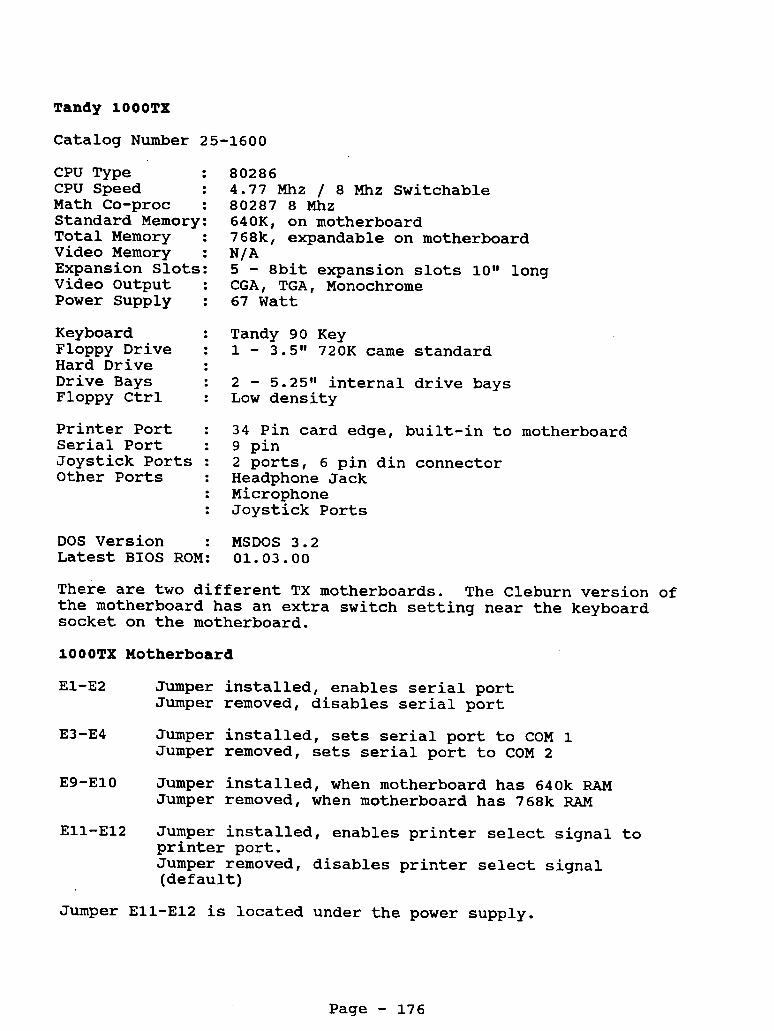
Tandy 100OTX
Catalog Number 25-1600
CPU Type CPU Speed Math Co-proc : Standard Memory: Total Memory : Video Memory : Expansion Slots: Video Output : Power Supply :
80286 4.77 Mhz / 8 Mhz Switchable 80287 8 Mhz 640K, on motherboard 768k, expandable on motherboard
5 - 8bit expansion slots lott long CGA, TGA, Monochrome 67 Watt
N/A
Keyboard : Tandy 90 Key Floppy Drive : 1 - 3.5" 720K came standard Hard Drive Drive Bays : 2 - 5.25" internal drive bays Floppy Ctrl : Low density
Printer Port : 34 Pin card edge, built-in to motherboard Serial Port : 9 pin Joystick Ports : 2 ports, 6 pin din connector Other Ports : Headphone Jack
: Microphone : Joystick Ports
DOS Version : MSDOS 3.2 Latest BIOS ROM: 01.03.00
There are two different TX motherboards. The Cleburn version of the motherboard has an extra switch setting near the keyboard socket on the motherboard.
10OOTX Motherboard
E1-E2 Jumper installed, enables serial port
E3-E4 Jumper installed, sets serial port to COM 1
E9-ElO Jumper installed, when motherboard has 640k RAM
Jumper removed, disables serial port
Jumper removed, sets serial port to COM 2
Jumper removed, when motherboard has 768k RAM
Ell-El2 Jumper installed, enables printer select signal to printer port. Jumper removed, disables printer select signal (default)
Jumper Ell-El2 is located under the power supply.
Page - 176

There are two other jumper locations E5-E6 and E7-E8. not have any pins and are not user options.
DIP Switch Setting
They do
1 - OFF Selects composite monochrome monitor ON Selects CGA monitor (Default)
2 - OFF Selects IRQ 5 for hard drive/IRQ 2 for video ON Selects IRQ 2 for hard drive/IRQ 5 for video
(default)
3 - OFF Disables IRQ 6, floppy controller IRQ ON Enables IRQ6, (default)
4 - OFF Disables IRQ 7, printer port IRQ ON Enables IRQ 7, (default)
NOTE: switch 2 to OFF. cards in the SX.
For some hard drives and hard cards, you will need to set This allows you to use standard XT controller
lOOOTX llCleburng@ Version Motherboard
El-E2 on - off -
E3-E4 on - off -
E9-ElO on - off -
Ell-El2 Off - on -
enables on board serial port - standard disables on board serial port selects Corn 1 - standard selects Com 2 selects 640k memory - standard selects 768k memory ties SLCTIN high - standard connects SLCTIN to the printer
Jumpers E7-E8 have no user options.
Switch S2
Pos 1 - Off - On -
Pos 2 - Off - On -
P o s 3 - Off - On -
Pos 4 - Off - On -
Switch S3
selects composite monochrome monitor selects color RGB monitor - standard disables on board INT5 enables on board INT5 - standard disables on board INT6 enables on board INT6 - standard disables on board INT7 enables on board INT7 - standard
Pos 1 61 2 towards the inside is for standard keyboard operation Pos 1 & 2 towards the outside is not used
Page - 177

System Memory
The lOOOTX came standard with 640K of memory on the motherboard. This is upgradeable to 768k by adding an additional 128K of memory. You will need 4 - 64 x 4 DRAM chips (DO NOT try to use 256k chips). Simply plug the 4 chips into the 4 empty sockets on the motherboard, at location U54, U55, U56 and U57. Then remove the jumper at location E9-ElO. video RAM. Without this extra memory, the video will use 16k to 64k of memory, depending on the video mode, from the lower 640k RAM. It is highly recommended that you install this extra 128K. The cost is minimal.
This extra memory is used for
This may cause you to run out of memory with some programs.
CPU and Math Co-Processor
The TX has an 80286 CPU running in the real mode. You can change the CPU out for a 386 module or 486 module by Improve. For more information see the chart on Speed Upgrades.
The TX uses a 80287 math co-processor. The socket is located at U15 on the motherboard. There are no jumpers or switches to set. Just plug it in.
1000TX 720X Sony MP-F63-01D 720k Floppy Drive
This is not a standard 720K floppy drive, power is supplied through the flat ribbon cable. You can use a modified version of a TEAC FD235HF or FD235F. Drive selection is handled by changing the drive select jumper on the drive. flat ribbon cable, as it is done on many compatibles.
Not through the
Sony Drive Settings
DSO drive A slide switch all the way to the back of the drive DS1 drive B slide switch second notch from rear of the drive.
Teac Floppy Drive Jumper Settings
DO - Drive select 0 D1 - Drive select 1
On some models of the Teac floppy drive, the DO,Dl and D2 may be labeled as DSO, DS1 and DS2.
NOTE: This is NOT a standard 3.5" floppy drive. It has been designed to draw the power through the data cable. use a standard 3.5" floppy drive as you will short out your system. The power is blocked from going to the 5 1/4" drive by the punched holes in the flat ribbon cable. standard floppy drive cable in this system.
DO NOT try to
DO NOT try to use a
Page - 178

When you add a 5 1/4Ig 360k floppy drive to the system, make sure the drive select jumper is set on D1 or DS1. location of the card edge connector on the back of the drive. You may have to twist the flat ribbon cable over for a proper connection. fit.
Depending on the
We recommend the TEAC 360k floppy drive for the best
Hard Drives
This system can handle either a hard card or hard drive. There are only two drive bays. that you don‘t loose the 2nd drive bay.
This system can use a standard Seagate STllM (for MFM) (for RLL) controller, when you set DIP switch 2 off. You can also run an IDE drive in this system with the proper IDE controller.
Note: A hard card is recommended so
or STllR
Serial Ports
This system has a 9 pin serial port located on the back. selectable between COM1, COM2 or disabled by changing the jumpers on the motherboard.
It is
See above for motherboard jumpers.
Clock Notes:
A I1Srnartt1 clock chip can be installed into this system. chart for clock chips for the exact location and software information.
See the
Keyboard Notes:
The lOOOSX does not use a standard keyboard interface. possible to connect a 1 0 1 style keyboard to these 1000‘s. You will either need a special keyboard converter Tandy part number 25-1030 (has been discontinued for a while) or a keyboard with the converter built-in. had a converter built-in.
It is
Tandy produced a keyboard, model 25-4038
There are also a couple of third party manufacturers that have made keyboards for the lOOO’s, When connecting up the Northgate keyboard, you will need to change the DIP switch setting found under the name plate.
they are Datadesk and Northgate.
Page - 179

Video Notes:
This system supports composite monochrome and standard CGA along with an extended CGA mode. This is also referred to as TGA. Standard CGA will allow you to display 4 colors, where as the TGA mode will allow you to display up to 16 colors. Very similar to EGA, but without the higher resolution. When connecting a composite monochrome monitor, you should turn DIP switch 1 OFF on the motherboard.
Display Modes
80 lines by 25 lines 40 lines by 25 lines
16 foreground colors / 8 background colors
Graphics Modes
Colors Resolution 4 320 x 200 16 320 x 200 16 160 x 200 2 640 x 200 4 640 x 200
VGA: This system can use VGA, however the VGA card must be able to run in an 8 bit mode. You will also need a VGA monitor, the CMll or CM5 are not VGA monitors.
You can connect the TX to a TV by using the composite monitor output on the back of the computer. press the F2 key during the boot up. computer to sync up to the TV in the 40 column mode. At the DOS prompt, just issue the command MODE 80. This will give you an 80 column display.
When booting the computer This will cause the
Page - 180

Printer Port The printer port is a 34 pin card edge.
Pin. Use Pin 1 3 5 7 9 11 13 15 17 19 21 23 25 27 29 31 33
STROBE DATA 0 DATA 1 DATA 2 DATA 3 DATA 4 DATA 5 DATA 6 DATA 7 Printer ACK BUSY Out of Paper Select Auto Feed Not Connected Ground Ground
Audio Jack 1 2 - Audio Out
Ground -
RGB Port (CGA Video) 1 - Ground 2 - Ground 3 4 - Green 5 - Blue 6 - Intensity 7 - Green - Mono 8 - Horizontal Sync 9 - Vertical Sync
RED -
2 4 6 8 10 12 14 16 18 20 22 24 26 28 30 32 34
Use Ground Ground Ground Ground Ground Ground Ground Ground Ground Ground Ground Ground Not Connected Printer Fault Printer Init Not Connected + 5 volts
Joystick Ports 1 - Y Axis 2 - X Axis
Ground 3 Switch #l 4 +5 Volts 5 Switch #2 6
- - - - Keyboard 1 - Clock
Data 2 Reset 3
4 - Ground 5 - + 5 volts 6 - Busy 7
- -
Type -
Page - 181

Floppy Drive Port - Internal 1 - Not Connected 3 - + 5 Volts 5 - + 5 Volts 7 - + 5 Volts 9 - + 5 Volts 11 - + 5 Volts 13 - Ground 15 - Ground 17 - Ground 19 - Ground 21 - Ground 23 - Ground 25 - Ground 27 - Ground 29 - + 12 Volts 31 - + 12 Volts 33 - + 12 Volts
2 4 6 8 10 12 14 16 18 20 22 24 26 28 30 32 34
Not Connected Not Connected Not Connected Index Drive 0 Select Drive 1 Select Drive 2 Select Motor On Direction Step Write Data Write Enable Track 0 Write Protect Read Data Disk Side Select Disk Change
NOTE: Power is supplied on the floppy drive controller cable to the 3.5" drives only. The floppy drive flat ribbon cable has holes punched in it to prevent the power from reaching the 5 1/4" drive. These power lines are normally ground lines.
Serial Port
CD RD TD DTR SG CTS RTS cs RI
Interrupts Interrupt
0 1 2 3 4 5 6 7
Carrier Detect Receive Data Transmit Data Data Terminal Ready Signal Ground Clear to Send Request to Send Clear To Send Ring Indicator
Available Function Timer Channel 0 Keyboard Video Corn Port 2 Com Port 1 Hard Disk Floppy Disk Controller Printer Port
Page - 182

1/0 Port 060 OCO OEO 1EO 200 2F8 320 370 378 3B0 3D0 3F2 3F8
Address PI0 Sound Generator Math Co-Processor Tandy Sound Joystick Interface COM 2 Hard Disk Interface Secondary Floppy Controller Printer Port Monochrome Display Adapter System Video Floppy Disk Controller COM 1
Page - 183

Tech Bulletins For The 1000's
The following is list of tech bulletins for the 1000's. If your system is working fine, them don't worry about them. should encounter a strange problem with your system, then you may want to check out the tech bulletin list under the description. If your symptom are like the description, you may want to contact your local repair center for more information.
If you
Computer's Catalog
Tech Bulletin Number
1000: 001
1000: 002
1000: 003
1000: 004
1000: 005
1000: 006
1000: 007
1000: 008
1000: 009
1000: 010
1000: 011
1000:012
1000: 013
25-1003
25-1000
25-1000
25-1000
25-1000
25-1000
25-1000
25-1000
25-1000
25-1000
25-1000
25-1000
25-1000
Description
The modification for the Hitachi Modem chip usage.
A correction for the possible cause of unit appearing dead and speaker squealing.
Installation procedure for memory expansion boards.
Describes test points on drives used in the Tandy 1000.
The circuit change required to the printer port to allow the use of IBM software and Tandy printers.
IBM PC compatibility improvement.
Intensity increase of the composite video output.
To stop FDC errors caused by ringing in the FDC clock.
Keyboard cable possible wiring problem.
Performance improvement of the joystick port.
Explanation of ROM differences.
Correction of missing negative 5 volt supply on expansion slots.
Installation of a grounding lug for hard drive upgrade.
Page - 184

1000: 014
1000: 015
1000: 016
1000: 017
1000: 018
1000: 019
1000: 020
1000:021
1000: 022
1000:023
1000: 024
1000: 025
1000:026
25-1007 Loss of data prevention on hard drive due to accidental enabling of write gate.
25-1000 Modification to decrease floppy 1/0 errors.
25-1000 To stop speaker noise during power UP
25-1000 To stop the production of extra long strobe pulses.
25-1000 The modification to stop use of ground write mode for DMA access.
25-1011 To eliminate DMA timing errors with slow peripherals.
25-1000A To correct or prevent system reset and poor sound level problems.
25-1003 To increase amplitude for modem output.
25-1000A To stop the problem of fuzzy or missing video on RGB output.
25-1000A To stop intermittent lockups because of timing problems.
25-1000A To correct an improperly installed component.
25-1000A To correct a DMA timing problem.
25-1000A To stop noise from the light pen socket when no light pen is installed.
1000: 027 25-1001 To enable the use of a tape cartridge with an internal hard in the Tandy 1000.
1000: 028 25-1000A A change to the floating state of IRQ4 to allow Deskmate to boot.
1000:029 25-1050 To enable the NCR sound generator IC to be used for Texas Instruments part.
1000: 030 25-1001 Troubleshooting outline for some hard drives that have startup problems.
Page - 185

1000:031
1000:032
1000: 033
1000: 034
1000:035
1000: 036
1000: 037
1000: 038
1000:039
1000: 040
1000:041
1000: 042
1000: 043
1000: 044
1000: 045
25-1050
25-1030
25-1600
25-1600
25-1000
25-1600
25-1001
25-1600
25-1600A
25-1401
25-1601
25-1052
25-1600
25-1600
25-1401
Outline of power supply adjustment procedures.
To give service information on the universal keyboard adapter.
To enable the use of optional video boards in the Tandy 1000TX.
To eliminate smearing or shadows of characters on video output.
Possibility of shorting or damaging when installing Express board into Tandy 1000's.
A correction to the main logic boards with C211 installed backwards.
To enable the use of the 25-1041 20 meg secondary hard drive with the Tandy 1000HD.
A modification to prevent the upper head shield from falling off.
To outline a manufacturing modification to prevent 8253 failures during power on.
To increase the volume level on computers with low volume.
To describe possible compatibility problems with early Tandy 1000TL's.
To prevent units with this supply from flickering back on.
To enable the use of the 20 meg IDE hard card for work properly in the 1000 TX.
To stop the computer from intermittently locking up.
To improve reliability of the serial port when direct connection to another computer.
Page - 186

1000:046
1000: 047
1000: 048
1000: 049
1000: 050
1000: 051
1000: 052
1000: 053
1000: 054
25-1401
25-1401
25-1050
25-1402
25-1602
25-1601
25-1402
25-1450
25-1051
1000: 055 25-1450
1000: 056 25-1603
1000: 057 25-1450
1000: 058 25-1452
1000: 059 25-1450
1000-060 25-1602
Identification and repair for lOOOSL and 1000SL/2 main logic boards.
To improve data transfers when using only 3.5 disk drives.
Modem installation procedure to prevent failures.
Specific sharp ROM set requires a board modification to allow proper address selection.
The prevention of possible file corruption when used with network adapters.
A correction of intermittent power- up problems on revision A, A-1, and A-2 PCB'S.
To document new diagnostic status codes and new error beep codes for the Tandy 1000SL/2 and 1000TL/2.
PS/2 mouse driver causes intermittent lockups in Deskmate.
Damage prevention to main logic boards caused by cracked power supply boards.
Improvement of monochrome video output when connected to a VM-5.
Improvement of monochrome video output when connected to a VM-5.
To insure reliable operation of the power supply.
Reprogramming a lOOORLX or 1000RLX/HD EPROM.
Using the 25-1087 external floppy with the lOOORL and 1000RL/HD.
2400 baud modem experiences intermittent initialization errors in some communications.
Page - 187