Embed Size (px)
Citation preview

TECHNICAL REPORT 1
1000 CONTINENTAL SQUARE KING OF PRUSSIA, PENNSYLVANIA
Carter Davis Hayes
Structural Option
January 13, 2008
Advisor: Dr. Hanagan
CARTER HAYES - STRUCTURAL 1000 CONTINENTAL SQUARE JANUARY 13, 2008
TECHNICAL REPORT 1
Page 2
TABLE OF CONTENTS
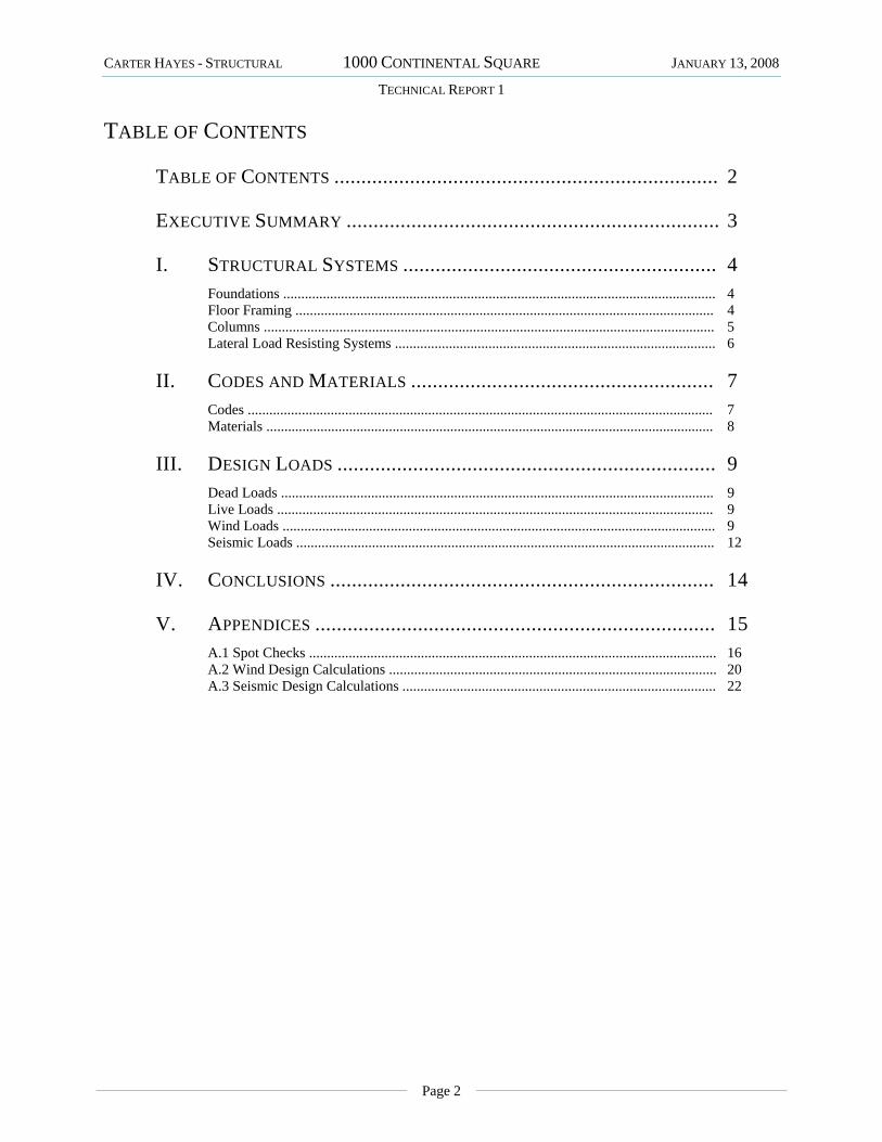
TABLE OF CONTENTS ....................................................................... 2
EXECUTIVE SUMMARY ..................................................................... 3
I. STRUCTURAL SYSTEMS .......................................................... 4 Foundations ........................................................................................................................ 4
Floor Framing .................................................................................................................... 4 Columns ............................................................................................................................. 5 Lateral Load Resisting Systems ......................................................................................... 6
II. CODES AND MATERIALS ........................................................ 7 Codes ................................................................................................................................. 7 Materials ............................................................................................................................ 8
III. DESIGN LOADS ...................................................................... 9 Dead Loads ........................................................................................................................ 9 Live Loads ......................................................................................................................... 9 Wind Loads ........................................................................................................................ 9 Seismic Loads .................................................................................................................... 12
IV. CONCLUSIONS ....................................................................... 14
V. APPENDICES .......................................................................... 15 A.1 Spot Checks ................................................................................................................. 16 A.2 Wind Design Calculations ........................................................................................... 20 A.3 Seismic Design Calculations ....................................................................................... 22

CARTER HAYES - STRUCTURAL 1000 CONTINENTAL SQUARE JANUARY 13, 2008
TECHNICAL REPORT 1
Page 3
EXECUTIVE SUMMARY
This paper is the first of three parts of the preliminary analysis of the design of the office building at 1000 Continental Square in King of Prussia, PA. This analysis will act as the basis for the later research around which my thesis will concentrate. The building is a high-end office space, featuring large, open floor plans with uninterrupted forty-foot bays along each side of the building. This building is located along the prominent intersection of Pennsylvania Routes 202, 76 and 422; and is in close proximity to a Pennsylvania Turnpike interchange and the King of Prussia Mall. The building has a partially sub-grade ground floor mainly for mechanical systems and storage with five floors of leasable space above that. The structural frame is steel with composite concrete slabs, and lateral loads are resisted by two moment frames along the long axis of the building and two eccentrically braced frames along the short axis. These systems are expounded upon later in this report, as well as calculations and spot checks verifying their adequacy. In typical cases, most members appear to be designed conservatively.
1000 Continental Square was designed to adhere to the 2004 Pennsylvania Uniform Construction Code which references IBC 2003 and ASCE 7-02. In my analysis and load calculations, I used IBC 2006 and ASCE 7-05, along with using some estimations and simplifications of floor areas and loadings, which could account for some discrepancies in my calculations when compared to those of the design engineer. Further findings of this report are located in the Conclusions section.

CARTER HAYES - STRUCTURAL 1000 CONTINENTAL SQUARE JANUARY 13, 2008
TECHNICAL REPORT 1
Page 4
I. STRUCTURAL SYSTEMS
FOUNDATIONS The foundations for 1000 Continental Square are a series of spread footings with continuous wall footings under the retaining walls located on the ground floor. The soils under the footings were found to withstand 4000 psf in most locations, according to the geotechnical report furnished by Pennoni Associates, Inc. on 24 of February 2004. Suitable bearing pressures were attained by deep dynamic compaction or partial soil exchange. Footing dimensions range from 4’ x 4’ x 1.5’ to 20’ x 20’ x 4’; however, typical footings are approximately 14’ x 14’ x 3’. Special 55’ x 18’ x 3.5’ spread footings are used under the braced frames. The tops of most footings are located 1.5’ below grade, and minimum bearing depth is 3’. Columns either bear directly on footings, or in some atypical situations, concrete piers are placed on top of the footings and columns bear on those. Footings have bottom reinforcement ranging from (7) #4’s to (16) #11’s with typical reinforcement being approximately (12) #9’s. The continuous wall footings are integrated into the spread footings they intersect, and their reinforcement is continuous throughout. Concrete in all footings has a minimum compressive strength, f’c = 3000 psi with a unit weight of 145 pcf. There is a 4” thick slab on grade which acts as the floor system for the ground floor and utilizes 4000 psi compressive strength concrete.
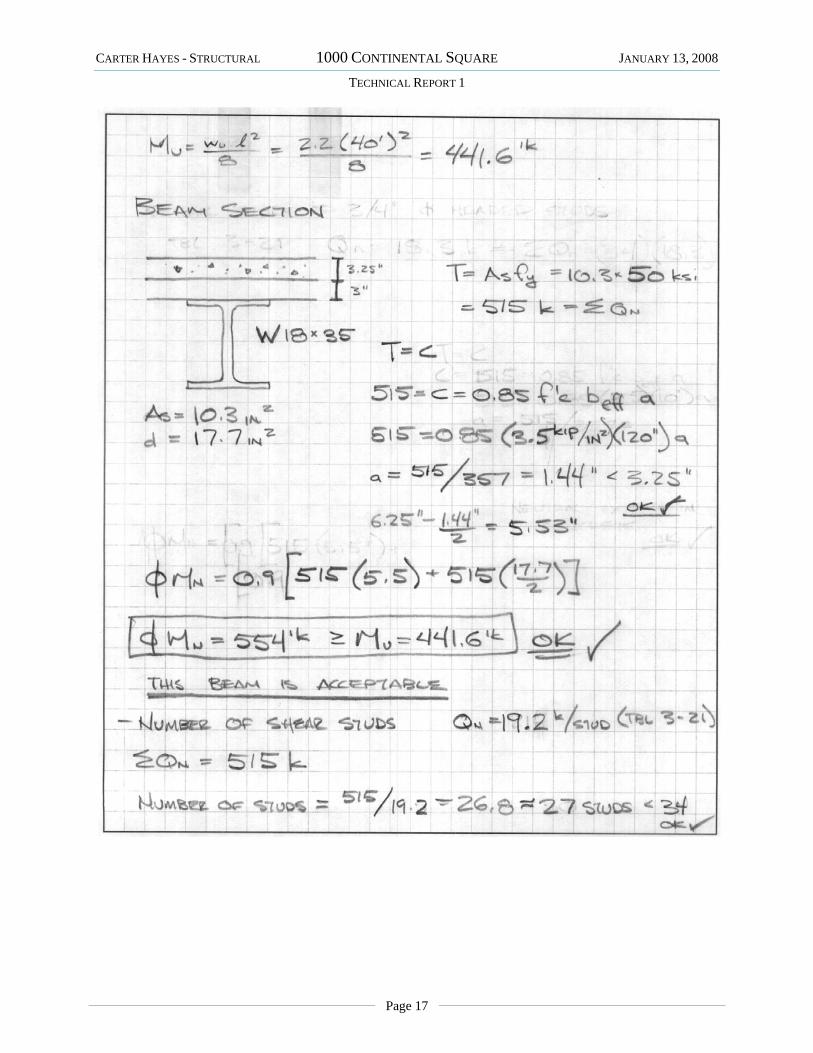
FLOOR FRAMING All the floor framing above grade in the 1000 Continental Square project are 6¼” composite slabs. They consist of 3¼” lightweight concrete over 3” deep 20 gauge galvanized composite floor deck. The slab is reinforced by one layer of 6 x 6 – W1.4 x W1.4 WWR, and has a weight of 115 pcf and a compressive strength of 3500 psi. This is supported by W 18 x 35’s

CARTER HAYES - STRUCTURAL 1000 CONTINENTAL SQUARE JANUARY 13, 2008
TECHNICAL REPORT 1
Page 5
spanning 40’ bays which tie into an assortment of girders spanning 30’; W 24 x 55’s being the most typical. Composite action is achieved through 6” long, ¾” diameter headed studs, approximately 34, evenly spaced per beam. The W 18’s feature a typical camber of 1.5”. Variations in design occur at architectural features, the elevator shafts, and intersections with the moment frames; elsewhere, the system is nearly identical on all floors.
COLUMNS The column grid for the building is laid out rectilinearly using three spans: 40’, 35’, 40’, in the N-S direction and (10) 30’ spans in the E-W, thereby creating large, uninterrupted, regular bays to simplify leasing. Column sizes vary between W 12 X 230’s on the first floor of the moment frames, to W 12 X 40’s for gravity columns on the top floors. Splice levels are located a maximum of 4ft above the second and fourth floors. Typical columns are W 12 x 152’s on the bottom floors, W 12 x 96’s on the middle floors, and W 12 x 40’ on the top levels. Typical columns are fixed to foundations with four ¾” diameter anchor rods with 1’ embed depths and 4” hooks.

CARTER HAYES - STRUCTURAL 1000 CONTINENTAL SQUARE JANUARY 13, 2008
TECHNICAL REPORT 1
Page 6
LATERAL LOAD RESISTING SYSTEMS 1000 Continental Square is reinforced against lateral loads by different systems along its long axis (E-W) and short axis (N-S). In the E-W direction, two moment frames fit into the existing grid along column lines B and D, and act over the full height of the building, and effectively, its full length. In the N-S direction, two full-height eccentrically braced frames fit off-grid, between lines B and C, and along column lines 3 and 9, to provide support for the short axis. These systems act to counter both wind and seismic forces, however, wind loads were found to control the design in this situation. There are two additional types of one story braced frames used in the building, mainly to support architectural elements, which are not analyzed in this report.

CARTER HAYES - STRUCTURAL 1000 CONTINENTAL SQUARE JANUARY 13, 2008
TECHNICAL REPORT 1
Page 7
II. CODES AND MATERIALS
CODES Building Code: 2004 Pennsylvania Uniform Construction Code
Building Subcode: International Building Code (IBC) 2003
Minimum Design Loads: American Society of Civil Engineers (ASCE), 7-02
Reinforced Concrete: American Concrete Institute (ACI), 318‐02
Concrete Reinforcing Steel Institute, Manual of Standard Practice, 27th Edition, March 2001
Precast Concrete: Precast/Prestressed Concrete Institute (PCI), Design Handbook 5th Edition
Steel Construction: American Institute of Steel Construction (AISC), Manual of Steel Construction, LRFD, 3rd Edition, 2001
Steel Decking: Steel Deck Institute, Design Manual

CARTER HAYES - STRUCTURAL 1000 CONTINENTAL SQUARE JANUARY 13, 2008
TECHNICAL REPORT 1
Page 8
MATERIALS
Cast in place concrete (normal weight 145 pcf)
Footings 3,000 psi
Topping slabs 3,000 psi
Lightweight slabs on metal deck (115 pcf) 3,500 psi
Normal weight slabs on metal deck 3,500 psi
Slabs on grade 4,000 psi
Walls and piers 4,000 psi
Cast in Place on precast 5,000 psi
Pourable fill 1,000 psi
Precast Concrete (normal weight 145 pcf)
Structural precast 5,000 psi
Reinforcing Steel
All types U.N.O. ASTM A615 60,000 psi
Structural Steel
W Shapes ASTM A992 50,000 psi
Channels, angles, and plates ASTM A36 36,000 psi
Round pipes ASTM A53 E or S 35,000 psi
Square and Rectangular HSS’s ASTM A500 46,000psi

CARTER HAYES - STRUCTURAL 1000 CONTINENTAL SQUARE JANUARY 13, 2008
TECHNICAL REPORT 1
Page 9
III. DESIGN LOADS
LIVE LOADS All floors 100 psf Due to the open floor plan, all areas are
assumed to be lobby or corridor space
Roof 20 psf Standard flat roof loading
Snow load 21 psf From ASCE 7-05 (see below)
DEAD LOADS Floor self weight 50 psf From steel deck manufacturer’s design tables
Roof self weight 5 psf From steel deck manufacturer’s design tables
Arch. Precast Panels 50 psf Material property
Superimposed DL 30 psf (see below)
MEP 20 psf Ceiling Finishes 5 psf Floor Finishes 5 psf
WIND LOADS Basic Wind Speed 90 mph Exposure Category B Enclosure Category Enclosed Wind Directionality Factor (Kd) 0.85 Importance Factor (I) 1.0 Topographic Factor (Kzt) 1.0 Gust Effect Factor (G) 0.828 (E-W) or 0.798 (N-S) Internal Pressure Coefficient 0.18
pf=0.7CeCtIpg Equation 7-1 Terrain Category B Section 6.5.6.2 Exposure Partially Table 7-2 Footnote Ce 1.0 Table 7-2 Ct 1.0 Table 7-3 I 1.0 Table 7-4 pg 30psf Figure 7-1
CARTER HAYES - STRUCTURAL 1000 CONTINENTAL SQUARE JANUARY 13, 2008
TECHNICAL REPORT 1
Page 10
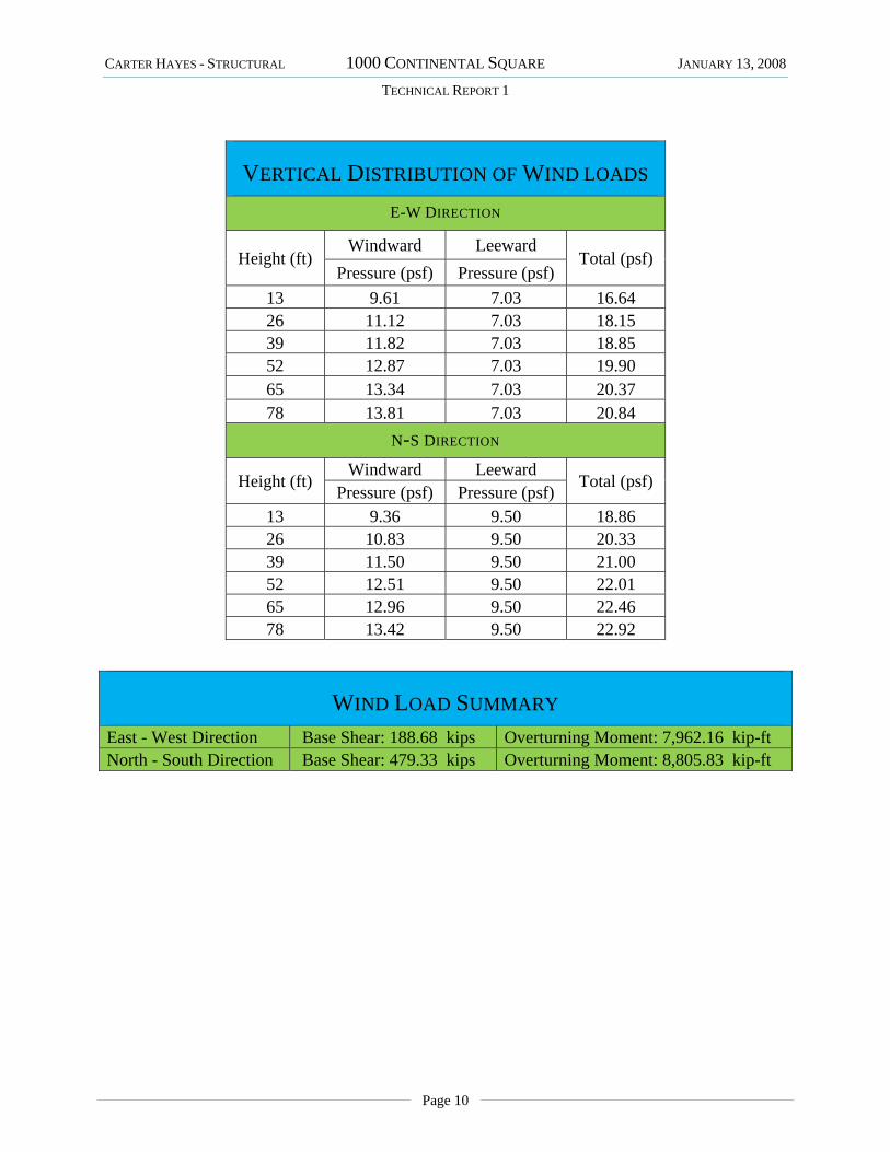
VERTICAL DISTRIBUTION OF WIND LOADS
E-W DIRECTION
Height (ft) Windward Leeward
Total (psf) Pressure (psf) Pressure (psf)
13 9.61 7.03 16.64 26 11.12 7.03 18.15 39 11.82 7.03 18.85 52 12.87 7.03 19.90 65 13.34 7.03 20.37 78 13.81 7.03 20.84
N-S DIRECTION
Height (ft) Windward Leeward
Total (psf) Pressure (psf) Pressure (psf) 13 9.36 9.50 18.86 26 10.83 9.50 20.33 39 11.50 9.50 21.00 52 12.51 9.50 22.01 65 12.96 9.50 22.46 78 13.42 9.50 22.92
WIND LOAD SUMMARY East - West Direction Base Shear: 188.68 kips Overturning Moment: 7,962.16 kip-ft North - South Direction Base Shear: 479.33 kips Overturning Moment: 8,805.83 kip-ft

CARTER HAYES - STRUCTURAL 1000 CONTINENTAL SQUARE JANUARY 13, 2008
TECHNICAL REPORT 1
Page 11

CARTER HAYES - STRUCTURAL 1000 CONTINENTAL SQUARE JANUARY 13, 2008
TECHNICAL REPORT 1
Page 12
SEISMIC LOADS
Item Design Value Code Basis
(ASCE 7-05) E-W N-S Hazard Exposure Group I Table 1-1 Performance Catagory B Table 11.6-1,2 Importance Factor (I) 1.00 Table 11.5-1 Spectral Acceleration for Short Periods (SS) 0.278 Figure 22-1 Spectral Acceleration for One Second Periods (S1) 0.06 Figure 22-2 Damped Design Spec. Resp. Acc. at Short Periods (SDS) 0.2224 Section 11.4.4 Damped Design Spec. Resp. Acc. at One Second Periods (SD1) 0.068 Section 11.4.4 Seismic Response Coefficient (CS) 0.0635 0.0278 Section 12.8.1.1 Soil Site Class C Section 20.3.3 Basic Structural System Comp. Steel Seismic Resisting System OSMF CEBF Response Modification Factor (R) 3.5 8 Table 12.2-1 Deflection Modification Factor (Cd) 3 4 Table 12.2-1
Analysis Procedure Utilized Equiv. Lat. Force
Design Base Shear 420 kips
VERTICAL DISTRIBUTION OF SEISMIC FORCES Height
(ft) E-W DIRECTION N-S DIRECTION
Story Shear (kips) 0 419.60 419.60 13 396.68 390.68 26 367.24 355.00 39 306.88 289.85 52 238.90 217.87 65 79.01 70.36
SEISMIC LOAD SUMMARY Base Shear: 419.60 kips Overturning Moment: 42,209.27 kip-ft

CARTER HAYES - STRUCTURAL 1000 CONTINENTAL SQUARE JANUARY 13, 2008
TECHNICAL REPORT 1
Page 13

CARTER HAYES - STRUCTURAL 1000 CONTINENTAL SQUARE JANUARY 13, 2008
TECHNICAL REPORT 1
Page 14
IV. CONCLUSIONS Through the analysis of the first technical report, I feel the results of my calculations are
acceptably close to those which were done by the design engineer; and therefore, I have made appropriate assumptions and simplifications to the overall structural system of the building. Although my calculations did not exactly replicate those of the current design, there many possible causes for these discrepancies.
The first difference is due to my limited knowledge of the final use of the building; broad assumptions were made on the uniformly distributed loads. Additionally, I used an average square foot estimate for floor space for this preliminary analysis, which should be refined in later in depth calculations. Discrepancies on wind loads are most likely the result of the use of different analysis methods. As for the seismic calculations, my use of an approximate period could be improved with a more accurate estimate, which will result from the creation of a full computer model, as well as refinement of the building weight. The last discrepancy in seismic is almost certainly the result of the difference in my seismic response modification factor for the braced frames, which I assume is a result of the use of different editions of the codes; however, I was unable to find a seismic force resisting system that had the same factors as those the designer used in any edition of the code. As a result, my calculated seismic base shear is within 10% of the design value, and my wind loads fall slightly below the range given by the Components and Cladding method of analysis.
Through my spot checks, it appears most members are conservatively designed. I find this worrisome, as the assumptions I made were fairly conservative, but my seismic base shear, wind loads, and spot checks have all came out under those of the existing design. Perhaps this implies I was not incorporating as large of a factor of safety into my estimates as I assumed. This will obviously become more evident, if it is indeed the case, as the project is further investigated. Nevertheless, I am confident that the margin of error is small enough at this preliminary stage to deem the results of this first technical report more than acceptable to give a very good understanding of the way the structural system of 1000 Continental Square acts under various loadings.

CARTER HAYES - STRUCTURAL 1000 CONTINENTAL SQUARE JANUARY 13, 2008
TECHNICAL REPORT 1
Page 15
V. APPENDICES
Page Left Intentionally Blank

CARTER HAYES - STRUCTURAL 1000 CONTINENTAL SQUARE JANUARY 13, 2008
TECHNICAL REPORT 1
Page 16
A.1 SPOT CHECKS
CARTER HAYES - STRUCTURAL 1000 CONTINENTAL SQUARE JANUARY 13, 2008
TECHNICAL REPORT 1
Page 17

CARTER HAYES - STRUCTURAL 1000 CONTINENTAL SQUARE JANUARY 13, 2008
TECHNICAL REPORT 1
Page 18

CARTER HAYES - STRUCTURAL 1000 CONTINENTAL SQUARE JANUARY 13, 2008
TECHNICAL REPORT 1
Page 19

CARTER HAYES - STRUCTURAL 1000 CONTINENTAL SQUARE JANUARY 13, 2008
TECHNICAL REPORT 1
Page 20
A.2 WIND DESIGN CALCULATIONS

CARTER HAYES - STRUCTURAL 1000 CONTINENTAL SQUARE JANUARY 13, 2008
TECHNICAL REPORT 1
Page 21

CARTER HAYES - STRUCTURAL 1000 CONTINENTAL SQUARE JANUARY 13, 2008
TECHNICAL REPORT 1
Page 22
A.3 SEISMIC DESIGN CALCULATIONS

CARTER HAYES - STRUCTURAL 1000 CONTINENTAL SQUARE JANUARY 13, 2008
TECHNICAL REPORT 1
Page 23

CARTER HAYES - STRUCTURAL 1000 CONTINENTAL SQUARE JANUARY 13, 2008
TECHNICAL REPORT 1
Page 24