Embed Size (px)
Citation preview

INS
TRU
CTIO
NM
AN
UA
L10" Power Miter Saw
(Model 36-070)
PART NO. 899880 (0012)Copyright © 2000 Delta Machinery
ESPAÑOL: PÁGINA 21To learn more about DELTA MACHINERY visit our website at: www.deltamachinery.com.For Parts, Service, Warranty or other Assistance,
please call 1-800-223-7278 (In Canada call 1-800-463-3582).

2
SAFETY RULESWoodworking can be dangerous if safe and proper operating procedures are not followed. As with all machinery, there are certainhazards involved with the operation of the product. Using the machine with respect and caution will considerably lessen the possi-bility of personal injury. However, if normal safety precautions are overlooked or ignored, personal injury to the operator may result.Safety equipment such as guards, push sticks, hold-downs, featherboards, goggles, dust masks and hearing protection can reduceyour potential for injury. But even the best guard won’t make up for poor judgment, carelessness or inattention. Always use com-mon sense and exercise caution in the workshop. If a procedure feels dangerous, don’t try it. Figure out an alternative procedurethat feels safer. REMEMBER: Your personal safety is your responsibility.
This machine was designed for certain applications only. Delta Machinery strongly recommends that this machine not be modifiedand/or used for any application other than that for which it was designed. If you have any questions relative to a particular applica-tion, DO NOT use the machine until you have first contacted Delta to determine if it can or should be performed on the product.
Technical Service ManagerDelta Machinery4825 Highway 45 NorthJackson, TN 38305(IN CANADA: 505 SOUTHGATE DRIVE, GUELPH, ONTARIO N1H 6M7)
WARNING: FAILURE TO FOLLOW THESE RULESMAY RESULT IN SERIOUS PERSONAL INJURY
1. FOR YOUR OWN SAFETY, READ INSTRUCTION MANUALBEFORE OPERATING THE TOOL. Learn the tool’s applicationand limitations as well as the specific hazards peculiar to it.
2. KEEP GUARDS IN PLACE and in working order.
3. ALWAYS WEAR EYE PROTECTION.
4. REMOVE ADJUSTING KEYS AND WRENCHES. Form habitof checking to see that keys and adjusting wrenches are removedfrom tool before turning it “on”.
5. KEEP WORK AREA CLEAN. Cluttered areas and benchesinvite accidents.
6. DON’T USE IN DANGEROUS ENVIRONMENT. Don’t usepower tools in damp or wet locations, or expose them to rain.Keep work area well-lighted.
7. KEEP CHILDREN AND VISITORS AWAY. All children andvisitors should be kept a safe distance from work area.
8. MAKE WORKSHOP CHILDPROOF – with padlocks, masterswitches, or by removing starter keys.
9. DON’T FORCE TOOL. It will do the job better and be safer atthe rate for which it was designed.
10. USE RIGHT TOOL. Don’t force tool or attachment to do a jobfor which it was not designed.
11. WEAR PROPER APPAREL. No loose clothing, gloves, neck-ties, rings, bracelets, or other jewelry to get caught in movingparts. Nonslip footwear is recommended. Wear protective haircovering to contain long hair.
12. ALWAYS USE SAFETY GLASSES. Wear safety glasses.Everyday eyeglasses only have impact resistant lenses; theyare not safety glasses. Also use face or dust mask if cuttingoperation is dusty. These safety glasses must conform to ANSIZ87.1 requirements. Note: Approved glasses have Z87 printedor stamped on them.
13. SECURE WORK. Use clamps or a vise to hold work whenpractical. It’s safer than using your hand and frees both hands tooperate tool.
14. DON’T OVERREACH. Keep proper footing and balance at alltimes.
15. MAINTAIN TOOLS IN TOP CONDITION. Keep tools sharpand clean for best and safest performance. Follow instructions forlubricating and changing accessories.
16. DISCONNECT TOOLS before servicing and when changingaccessories such as blades, bits, cutters, etc.
17. USE RECOMMENDED ACCESSORIES. The use of acces-sories and attachments not recommended by Delta may causehazards or risk of injury to persons.
18. REDUCE THE RISK OF UNINTENTIONAL STARTING.Make sure switch is in “OFF” position before plugging in powercord.
19. NEVER STAND ON TOOL. Serious injury could occur if thetool is tipped or if the cutting tool is accidentally contacted.
20. CHECK DAMAGED PARTS. Before further use of the tool, aguard or other part that is damaged should be carefully checked toensure that it will operate properly and perform its intended func-tion – check for alignment of moving parts, binding of movingparts, breakage of parts, mounting, and any other conditions thatmay affect its operation. A guard or other part that is damagedshould be properly repaired or replaced.
21. DIRECTION OF FEED. Feed work into a blade or cutteragainst the direction of rotation of the blade or cutter only.
22. NEVER LEAVE TOOL RUNNING UNATTENDED. TURNPOWER OFF. Don’t leave tool until it comes to a complete stop.
23. DRUGS, ALCOHOL, MEDICATION. Do not operate tool whileunder the influence of drugs, alcohol or any medication.
24. MAKE SURE TOOL IS DISCONNECTED FROM POWERSUPPLY while motor is being mounted, connected or re-connected.
25. THE DUST GENERATED by certain woods and wood prod-ucts can be injurious to your health. Always operate machinery inwell ventilated areas and provide for proper dust removal. Usewood dust collection systems whenever possible.
26. WARNING: SOME DUST CREATED BY POWERSANDING, SAWING, GRINDING, DRILLING, AND OTHERCONSTRUCTION ACTIVITIES contains chemicals known tocause cancer, birth defects or other reproductive harm. Someexamples of these chemicals are:• lead from lead-based paints,• crystalline silica from bricks and cement and other masonry
products, and• arsenic and chromium from chemically-treated lumber. Your risk from these exposures varies, depending on how oftenyou do this type of work. To reduce your exposure to thesechemicals: work in a well ventilated area, and work withapproved safety equipment, such as those dust masks that arespecially designed to filter out microscopic particles.
SAVE THESE INSTRUCTIONS

33
ADDITIONAL SAFETY RULESFOR MITER SAWS
1. USE ONLY CROSS-CUTTING SAW BLADES.WHEN USING CARBIDE-TIPPED BLADES, MAKESURE THEY HAVE A NEGATIVE HOOK ANGLE. DONOT USE BLADES WITH DEEP GULLETS AS THEYCAN DEFLECT AND CONTACT GUARD.
2. DO NOT OPERATE the miter saw until it is com-pletely assembled and installed according to the instruc-tions.
3. IF YOU ARE NOT thoroughly familiar with the oper-ation of compound miter saws, obtain advice from yoursupervisor, instructor or other qualified person.
4. DO NOT perform any operation freehand. Secure orclamp workpiece firmly against fence.
5. KEEP HANDS OUT OF PATH of saw blade. If theworkpiece you are cutting would cause your hand to bewithin hazard zone of the saw blade, the workpieceshould be clamped in place before making cut.
6. BE SURE blade is sharp, runs freely and is free ofvibration.
7. ALLOW the motor to come up to full speed beforestarting cut.
8. KEEP motor air slots clean and free of chips.
9. ALWAYS MAKE SURE all clamp handles are tightbefore cutting, even if the table is positioned in one of thepositive stops.
10. BE SURE blade and flanges are clean and that arborscrew is tightened securely.
11. USE only blade flanges specified for your saw.
12. NEVER use blades larger or smaller in diameter thanten inches.
13. NEVER apply lubricants to the blade when it isrunning.
14. ALWAYS check the blade for cracks or damagebefore operation. Replace cracked or damaged bladeimmediately.
15. NEVER use blades recommended for operation atless than 6000 RPM.
16. DO NOT operate the saw without guards in place.
17. ALWAYS keep the lower blade guard in place andoperating properly.
18. NEVER reach around or behind saw blade.
19. MAKE SURE blade is not contacting workpiecebefore switch is turned on.
20. NEVER lock the switch in the “ON” position.
21. AFTER COMPLETING CUT, release power switchand wait for coasting blade to stop before returning sawto raised position.
22. TURN OFF tool and wait for saw blade to stopbefore moving workpiece or changing settings.
23. DO NOT remove jammed or cut-off pieces until bladehas stopped.
24. NEVER cut ferrous metals or masonry.
25. NEVER recut small pieces.
26. PROVIDE adequate support to the sides of the sawtable for long workpieces.
27. NEVER use the miter saw in an area with flammableliquids or gases.
28. NEVER use solvents to clean plastic parts. Solventscould possibly dissolve or otherwise damage the material.Only a soft damp cloth should be used to clean plasticparts.
29. DISCONNECT power before changing blades or ser-vicing.
30. DISCONNECT saw from power source and clean themachine before leaving it.
31. MAKE SURE the work area is cleaned before leavingthe machine.
32. THE USE of attachments and accessories not rec-ommended by Delta may result in the risk of injuries.
33. SHOULD any part of your miter saw be missing,damaged or fail in any way, or any electrical componentfail to perform properly, shut off switch and remove plugfrom power supply outlet. Replace missing, damaged orfailed parts before resuming operation.
34. ADDITIONAL INFORMATION regarding the safeand proper operation of this product is available from theNational Safety Council, 1121 Spring Lake Drive, Itasca,IL 60143-3201, in the Accident Prevention Manual forIndustrial Operation and also in the Safety Data Sheetsprovided by the NSC. Please also refer to the AmericanNational Standard Institute ANSI 01.1 SafetyRequirements for Woodworking Machinery and the U.S.Department of Labor OSHA 1910.213 Regulations.
35. SAVE THESE INSTRUCTIONS. Refer to them oftenand use them to instruct others.

44
UNPACKING
1. Remove the miter saw and all loose items from thecarton. IMPORTANT: DO NOT LIFT THE MITER SAWBY THE SWITCH HANDLE AS THIS MAY CAUSE MIS-ALIGNMENT. ALWAYS LIFT THE MACHINE BY THEBASE OR CARRYING HANDLE. Fig. 2, illustrates themachine and all loose items after they have beenremoved from the carton.
1 - Miter Saw2 - Wrenches for changing the blade3 - Table lock handle
ASSEMBLY INSTRUCTIONSWARNING: FOR YOUR OWN SAFETY, DO NOT CONNECT THE MITER SAW TO THE POWER SOURCE UNTIL
THE MACHINE IS COMPLETELY ASSEMBLED AND YOU HAVE READ AND UNDERSTOOD THE ENTIRE OWNERSMANUAL.
MOVING CUTTERHEAD TO THE UP POSITION
1. Push down on switch handle (A) Fig. 3, and pull outcuttinghead lockpin (B).
2. The cuttinghead (C) can then be moved to the upposition, as shown in Fig. 4.
Fig. 2
Fig. 3
Fig. 4
1
A
2
3
B
C

55
ASSEMBLINGTABLE LOCK HANDLE
1. Thread table lock handle (A) Fig. 5, into the thread-ed hole (B) of the arm bracket.
ROTATING TABLE TO 90 DEGREE POSITION
1. Loosen table lock handle (A) Fig. 6, one or two turnsand depress index lever (B) to release 45 degree positivestop.
2. Rotate table to the left until index stop engages withthe 90 degree positive stop (C) Fig. 6. Then tighten tablelock handle (A).
ASSEMBLING DUST BAG(OPTIONAL)
1. Assemble dust bag (A) Fig. 7, to the dust spout (B)making sure the wire ring (C) is engaged with the groovein the spout.
FASTENING MITER SAWTO SUPPORTING SURFACE
Before operating your compound miter saw, make sureit is firmly mounted to a sturdy workbench or other sup-porting surface. Four holes are provided, two of which areshown at (A) Fig. 8, for fastening the saw to a supportingsurface.
When frequently moving the saw from place to place wesuggest that the saw be mounted to a 3/4" piece ofplywood. The saw can then be easily moved from placeto place and the plywood clamped to the supportingsurface using “C” clamps.
Fig. 5
Fig. 6
Fig. 7
Fig. 8
A
B
ABC
A
BC
A

6
CONNECTING SAW TO POWER SOURCEPOWER CONNECTIONS
A separate electrical circuit should be used for your tools. This circuit should not be less than #12 wire and should beprotected with a 20 Amp time lag fuse. If an extension cord is used, use only 3-wire extension cords which have 3-prong grounding type plugs and 3-pole receptacles which accept the tool’s plug. Before connecting the motor to thepower line, make sure the switch is in the “OFF” position and be sure that the electric current is of the same charac-teristics as indicated on the tool. All line connections should make good contact. Running on low voltage will dam-age the motor.
MOTOR SPECIFICATIONSYour miter saw is wired for 110-120 volt, 60 HZ alternating current. Before connecting the miter saw to the powersource, make sure the switch is in the “OFF” position. The motor provides a no-load speed of 5200 RPM.
GROUNDING INSTRUCTIONSWARNING: THIS TOOL MUST BE GROUNDED WHILE IN USE TO PROTECT THE OPERATOR FROMELECTRIC SHOCK.
Fig. 9 Fig. 10
GROUNDED OUTLET BOX
CURRENTCARRYING
PRONGS
GROUNDING BLADEIS LONGEST OF THE 3 BLADES
GROUNDED OUTLET BOX
GROUNDINGMEANS
ADAPTER
2. Grounded, cord-connected tools intended for use ona supply circuit having a nominal rating less than 150volts: This tool is intended for use on a normal 120-volt circuit and has a grounded plug that looks like the plugillustrated in Fig. 9.If a properly grounded outlet is not available, a temporaryadapter, shown in Fig. 10, may be used for connecting the3-prong grounding type plug to a 2-prong receptacle. Thetemporary adapter should be used only until a properlygrounded outlet can be installed by a qualified electrician.The green colored rigid ear, lug, or the like extending fromthe adapter must be connected to a permanent groundsuch as a properly grounded outlet box cover. Wheneverthe adapter is used, it must be held in place with a metalscrew. NOTE: In Canada, the use of a temporary adapter is notpermitted by the Canadian Electric Code.
WARNING: IN ALL CASES, MAKE CERTAIN THERECEPTACLE IN QUESTION IS PROPERLY
GROUNDED. IF YOU ARE NOT SURE HAVE A CERTI-FIED ELECTRICIAN CHECK THE RECEPTACLE.
1. All grounded, cord-connected tools: In the event of amalfunction or breakdown, grounding provides a path ofleast resistance for electric current to reduce the risk ofelectric shock. This tool is equipped with an electric cordhaving an equipment-grounding conductor and a ground-ing plug. The plug must be plugged into a matching outletthat is properly installed and grounded in accordance withall local codes and ordinances.
Do not modify the plug provided - if it will not fit the outlet,have the proper outlet installed by a qualified electrician.
Improper connection of the equipment-grounding con-ductor can result in risk of electric shock. The conductorwith insulation having an outer surface that is green withor without yellow stripes is the equipment-grounding con-ductor. If repair or replacement of the electric cord or plugis necessary, do not connect the equipment groundingconductor to a live terminal.
Check with a qualified electrician or service personnel ifthe grounding instructions are not completely understood,or if in doubt as to whether the tool is properly grounded.
Use only 3-wire extension cords that have 3-pronggrounding type plugs and 3-hole receptacles that acceptthe tool’s plug, as shown in Fig. 9.
Repair or replace damaged or worn cord immediately.

777
Use proper extension cords. Make sure your extensioncord is in good condition and is a 3-wire extension cordwhich has a 3-prong grounding type plug and a 3-polereceptacle which will accept the tool’s plug. When usingan extension cord, be sure to use one heavy enough tocarry the current of the saw. An undersized cord willcause a drop in line voltage, resulting in loss of powerand overheating. Fig. 11, shows the correct gauge touse depending on the cord length. If in doubt, use thenext heavier gauge. The smaller the gauge number, theheavier the cord.
Fig. 11
EXTENSION CORDSRECOMMENDED EXTENSION CORD SIZES FOR USE
WITH STATIONARY ELECTRIC TOOLS
OPERATING INSTRUCTIONS
FOREWORD
Delta Model 36-070 is a 10" Power Miter Saw designed to cut wood. Cross cutting and miter cutting are easy and accu-rate. It can crosscut up to 2-1/4" x 5-3/4", miter at 45 both left and right 2-1/4" x 4-1/8". It has positive miter stops at 0,22.5, and 45 degrees both left and right, and is accurate to one half degree.

888
STARTING AND STOPPING MACHINE
To start the machine, depress switch trigger (A) Fig. 12.To stop the machine, release the switch trigger.
This miter saw is equipped with an automatic electricblade brake. As soon as the switch trigger (A) Fig. 12, isreleased, the electric brake is activated and stops theblade in seconds.
WARNING: A TURNING SAW BLADE CAN BEHAZARDOUS. AFTER COMPLETING CUT, RELEASESWITCH TRIGGER (A) FIG. 12, TO ACTIVATE BLADEBRAKE. KEEP CUTTINGHEAD DOWN UNTIL BLADEHAS COME TO A COMPLETE STOP.
WARNING: THE TORQUE DEVELOPED DURINGBRAKING MAY LOOSEN THE ARBOR SCREW. THEARBOR SCREW SHOULD BE CHECKED PERIOD-ICALLY AND TIGHTENED IF NECESSARY.
LOCKING SWITCH IN THE “OFF” POSITION
IMPORTANT: When the miter saw is not in use, theswitch should be locked in the “OFF” position using apadlock (B) Fig. 13, (with 3/16" diameter shackle)through the two holes (A )Fig. 12 in the switch plate, asshown in (A) Fig. 12. NOTE: Padlock shown is availableas accessory Model 50-325.
ROTATING TABLE FOR MITER CUTTING
Your miter saw will cut any angle from a straight 90degree cut to 47 degrees right and left. Simply loosenlock handle (A) Fig. 14, one or two turns, depress indexlever (B) and move the control arm to the desired angle.THEN TIGHTEN LOCK HANDLE (A).
The miter saw is equipped with positive stops at the 0,22-1/2 and 45 degree right and left positions. Simplyloosen lock handle (A) Fig. 14, and move the control armuntil the bottom of the index lever (B) engages into oneof the positive stops, four of which are shown at (C).THEN TIGHTEN LOCK HANDLE (A). To disengage thepositive stop, depress index lever (B).IMPORTANT: ALWAYS TIGHTEN LOCK HANDLE (A)FIG. 14, BEFORE CUTTING.
POINTER AND SCALEA pointer (A) Fig. 15, is supplied which indicates theactual angle of cut. Each line on the scale (B) represents1/2 degree. In effect, when the pointer is moved from oneline to the next on the scale, the angle of cut is changedby 1/2 degree.
Fig. 12
Fig. 13
Fig. 14
Fig. 15
A
B
B
AC
B
A

999
Fig. 16
LOCKING CUTTINGHEAD IN THE DOWN POSITION
When transporting the miter saw, the cuttingheadshould always be locked in the down position. This canbe accomplished by lowering the cuttinghead (A) Fig.16, and pushing pin (B) until other end of pin (B) engageswith hole in cutting arm. IMPORTANT: NEVER CARRYTHE MITER SAW BY THE SWITCH HANDLE ORTABLE CONTROL HANDLE AS THIS MAY CAUSEMISALIGNMENT. ALWAYS LIFT THE MACHINE BYTHE BASE OR CARRYING HANDLE.
REAR SUPPORT/CARRYING HANDLE
A rear support bar (A) Fig. 17, is provided to prevent themiter saw from tipping to the rear when the cuttingheadis returned to the up position after a cut has been made.For maximum support the bar (A) should be pulled outas far as possible.
The support bar (A) also acts as a carrying handle, asshown in Fig. 18, when transporting the saw.
ADJUSTING DOWNWARD TRAVEL OF SAW BLADEThe downward travel of the saw blade can be limited toprevent the saw blade from contacting any metal sur-faces of the machine.Before adjusting downward travel, DISCONNECT THEMACHINE FROM THE POWER SOURCE and lower theblade as far as possible. Rotate the blade by hand tomake certain the teeth do not contact any metal sur-faces.This adjustment is made by loosening lock nut (A)Fig. 19, and turning the adjusting screw (B) in or out untilthe blade lowers to the desired position. Then tightenlock nut (A).
Fig. 17
Fig. 18
Fig. 19
ADJUSTMENTS
A
B
A
A B

10
ADJUSTING BLADE PARALLEL TO TABLE OPENING1. DISCONNECT THE SAW FROM THE POWERSOURCE.
2. Lower the cuttinghead and check to see if the sawblade (A) Fig. 20, is parallel to the left edge (B) of thetable opening.
3. If an adjustment is necessary, loosen two screws,one of which is shown at (C) Fig. 20, and move the cut-tinghead until the blade (A) is parallel with the left edge(B) of the table opening. Then tighten two screws (C).
ADJUSTING FENCE 90 DEGREES TO BLADEIf the fence (A) Fig. 21, is ever removed from the saw itshould be adjusted so it is 90 degrees to the blade whenit is replaced, as follows:
1. DISCONNECT THE SAW FROM THE POWERSOURCE.
2. This adjustment should be made only after the bladehas been adjusted parallel to table opening, as previ-ously explained.
3. Using a square (B) Fig. 21, place one end of thesquare against the fence (A) and the other end againstthe slot in the table as shown.
4. If an adjustment is necessary, loosen the two screws(C) Fig. 22, and adjust fence 90 degrees to the tableopening. Then tighten the two screws (C).
ADJUSTING POINTERIf it becomes necessary to adjust the pointer (A) Fig. 23,simply loosen screw (B), adjust the pointer accordinglyand tighten screw (B).
Fig. 20
Fig. 21
Fig. 22
Fig. 23
A
AA
A B
C C
C
B
B

111111
1. An ideal accessory for use with your miter saw is the36-221 Work Clamp, shown at (A) Fig. 24.
2. Two holes (B) Fig. 25, are provided in the base of themiter saw enabling you to use the clamp (A) on either theright or left hand side of the saw blade.
WARNING: Keep hands out of path of saw blade.If the workpiece you are cutting would cause yourhand to be within 4 inches of the saw blade, theworkpiece should be clamped in place before mak-ing cut.
Fig. 24
Fig. 25
TYPICAL OPERATIONS AND HELPFUL HINTS1. Before cutting, make certain the table is set at the correct angle and firmly locked in place.
2. Before cutting, determine that the workpiece is the right size for the saw.
3. Place the workpiece on the table and hold it firmly against the fence.
4. For best results cut at a slow, even cutting rate.
5. If the workpiece you are cutting causes your hand to be within 4 inches of the saw blade, the workpiece must be clamped to the fence before cutting.
6. Never attempt any freehand cutting (wood that is not held firmly against the fence and table).
USING ACCESSORY 36-221 WORK CLAMP
A
A
B

12
1. Your miter saw has the capacity to cut standard 2 x4’s laying flat or on edge, at the 45 degree right and leftmiter angles as shown in Figs. 26 and 27.
2. A standard 2 x 6 can easily be cut in the 90 degreestraight cut-off position in one pass, as shown in Fig. 28.
3. Cutting a standard 4 x 4 is easily accomplished withyour miter saw in one pass, as shown in Fig. 29.
Fig. 26
Fig. 27
Fig. 28
Fig. 29
GENERAL CUTTING OPERATIONS
131313
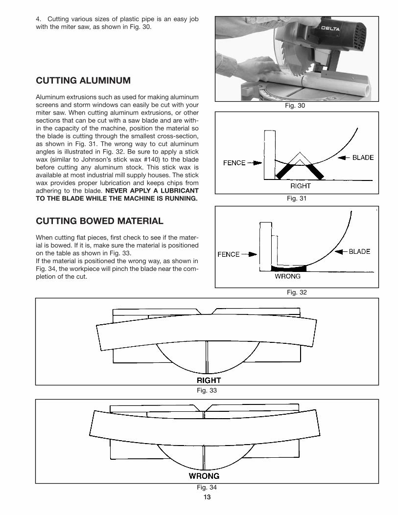
4. Cutting various sizes of plastic pipe is an easy jobwith the miter saw, as shown in Fig. 30.
CUTTING ALUMINUM
Aluminum extrusions such as used for making aluminumscreens and storm windows can easily be cut with yourmiter saw. When cutting aluminum extrusions, or othersections that can be cut with a saw blade and are with-in the capacity of the machine, position the material sothe blade is cutting through the smallest cross-section,as shown in Fig. 31. The wrong way to cut aluminumangles is illustrated in Fig. 32. Be sure to apply a stickwax (similar to Johnson’s stick wax #140) to the bladebefore cutting any aluminum stock. This stick wax isavailable at most industrial mill supply houses. The stickwax provides proper lubrication and keeps chips fromadhering to the blade. NEVER APPLY A LUBRICANTTO THE BLADE WHILE THE MACHINE IS RUNNING.
CUTTING BOWED MATERIAL
When cutting flat pieces, first check to see if the mater-ial is bowed. If it is, make sure the material is positionedon the table as shown in Fig. 33.If the material is positioned the wrong way, as shown inFig. 34, the workpiece will pinch the blade near the com-pletion of the cut.
Fig. 31
Fig. 32
Fig. 30
Fig. 33
Fig. 34

14
1. There are several methods that can be used to cutcrown mouldings on the miter saw. The method shownin Fig. 35, illustrates the contact surfaces (the surfacesthat contact the wall and ceiling) of the crown mouldingheld firmly against the fence and table of the miter saw.This method is acceptable when making a small numberof cuts but would not be practical for a production appli-cation as it may be difficult to firmly hold the work in thisposition. Also, this method means that the crownmoulding must be positioned on the table in the upsidedown position.
2. When a large number of repetitive cuts of crownmoulding are required we suggest the use of fillerblocks, as shown in Fig. 36 through Fig. 39. The majori-ty of crown mouldings have contact surfaces at 52 and38 degrees to the rear surface of the moulding and theseangles must be utilized when jointing the face of the fillerblock. For crown mouldings with different angles, appro-priate filler blocks can be produced.
3. Fig. 36 and Fig. 37, illustrate the filler block fastenedto the miter saw fence with the face of the filler blockextending outward from the top of the fence and downto the surface of the table. When the filler block is posi-tioned in this manner, the crown moulding must be posi-tioned on the table in the upside down position. Thismeans that the surface of moulding that contacts theceiling is against the table.
Fig. 35
Fig. 37
Fig. 38
Fig. 39
Fig. 36
4. Fig. 38 and Fig. 39, illustrate the filler block fastenedto the miter saw fence with the face of the filler blockextending inward toward the fence from the top to thebottom. When the filler block is positioned in this man-ner, the crown moulding is placed on the table in thesame position as it would be when nailed between theceiling and wall.
CUTTING CROWN MOULDINGS
FILLER BLOCK FOR CROWN MOULDING IF JOINT IS TO HAVE MITEREDCORNER FIT OR COPE CUT
FILLER BLOCK FOR CROWN MOULDING IF JOINT IS TO HAVE MITEREDCORNER FIT OR COPE CUT

1515
5. Fasten the filler blocks to the fence using woodscrews (A) through the two holes provided on eachfence half, as shown in Fig. 40. This enables you to eas-ily remove the filler blocks when not in use and quicklyreassemble them to the fence when needed.
Fig. 42
Fig. 40
Fig. 41
6. Fig. 41, illustrates the miter saw arm in the 45 degree right miter position and the filler blocks fastened to the fenceso that the moulding will be in the same position as it would be when nailed between the ceiling and wall.
When making this cut the moulding (B) on the left of the saw blade will be for an outside corner and the moulding (C)on the right of the saw blade will be for an inside corner.
To cut the mating pieces for mouldings (B) and (C) Fig. 41, simply rotate the miter saw arm to the 45 degree left miterposition and make the cut, as shown in Fig. 42. In this case the moulding (D) on the left of the saw blade will be for aninside corner and the moulding (E) on the right of the saw blade will be for an outside corner.
A
A
C
EB
D

16
CHANGING THE BLADE
WARNING: USE ONLY CROSS-CUTTING SAWBLADES. WHEN USING CARBIDE TIPPED BLADES,MAKE SURE THEY HAVE A NEGATIVE HOOK ANGLE.DO NOT USE BLADES WITH DEEP GULLETS ASTHEY CAN DEFLECT AND CONTACT THE GUARD.USE ONLY 10" DIAMETER SAW BLADES WHICH ARERATED FOR 6000 RPM OR HIGHER AND HAVE 5/8"DIAMETER ARBOR HOLES.
1. DISCONNECT THE MACHINE FROM THEPOWER SOURCE.
2. Loosen screw (A) Fig. 43, and rotate cover (B) to therear as shown in Fig. 44.
3. To remove the saw blade, insert hex wrench (C)Fig. 45, into the hex hole located on the rear end of thearbor shaft, to keep the shaft from turning.
4. Using wrench (D) Fig. 46, loosen arbor screw (E) byturning it clockwise
5. Remove arbor screw (E) Fig. 46, outside bladeflange (F) and saw blade (G) from saw arbor.
6. Assemble new saw blade MAKING CERTAIN TEETHOF SAW BLADE ARE POINTING DOWN AT THE FRONTand re-assemble outside blade flange (F) Fig. 46, andarbor screw (E) by turning it counterclockwise usingwrench (D) Fig. 46. At the same time use hex wrench (C)Fig. 45, to keep the arbor from turning.
7. Replace screw and cover that was rotated to therear in STEP 2.
WARNING: REMOVE WRENCHES (C) FIG. 45,AND (D) FIG. 46, BEFORE TURNING ON THE POWER.
Fig. 43
Fig. 44
Fig. 45
Fig. 46
MAINTENANCE
AB
B
C
EF
G
D

171717
BRUSH INSPECTION AND REPLACEMENT
CAUTION: BEFORE INSPECTING THE BRUSHES,DISCONNECT THE MACHINE FROM THE POWERSOURCE.
Brush life varies. It depends on the load on the motor.Check the brushes after the first 50 hours of use for anew machine or after a new set of brushes has beeninstalled. After the first check, examine them after about10 hours of use until such time that replacement is nec-essary. To inspect the brushes, proceed as follows:
1. Remove three screws (A) Fig. 47, and remove motorcover (B).
2. The brushes are located in the two holders (C) Fig.48. Remove spade type terminal connector (D) and pullout brush holders (C).
3. Fig. 49, illustrates one of the brushes (E) removedfrom the holder (C). When the carbon on either brush (E)is worn to 3/16" in length or if either spring (F) or shuntwire is burned or damaged in any way, replace bothbrushes. If the brushes are found serviceable afterremoving, reinstall them in the same position asremoved.
Fig. 48
Fig. 49
Fig. 47
Fig. 50
TABLE HAZARD AREAWARNING: THE AREA INSIDE THE TWO RED LINES (A) FIG. 50, ON THE TABLE IS DESIGNATED AS A HAZ-
ARD ZONE. NEVER PLACE YOUR HANDS INSIDE THIS AREA WHILE THE TOOL IS BEING OPERATED.
A
B
C C
DD
E
F
C
A
A

181818
NOTES

191919
NOTES

2020
Delta Building Trades and Home Shop MachineryTwo Year Limited Warranty
Delta will repair or replace, at its expense and at its option, any Delta machine, machine part, or machine accessory whichin normal use has proven to be defective in workmanship or material, provided that the customer returns the product pre-paid to a Delta factory service center or authorized service station with proof of purchase of the product within two yearsand provides Delta with reasonable opportunity to verify the alleged defect by inspection. Delta may require that electricmotors be returned prepaid to a motor manufacturer’s authorized station for inspection and repair or replacement. Deltawill not be responsible for any asserted defect which has resulted from normal wear, misuse, abuse or repair or alterationmade or specifically authorized by anyone other than an authorized Delta Service facility or representative. Under no cir-cumstances will Delta be liable for incidental or consequential damages resulting from defective products. This warrantyis Delta’s sole warranty and sets forth the customer’s exclusive remedy, with respect to defective products; all other war-ranties, express or implied, whether of merchantability, fitness for purpose, or otherwise, are expressly disclaimed by Delta.
Printed in U.S.A.
ACCESSORIESA complete line of accessories are available from your Delta Supplier, Porter-Cable � Delta FactoryService Centers, and Delta Authorized Service Stations. Please visit our Web Sitewww.deltamachinery.com for a catalog or for the name of your nearest supplier.
WARNING: Since accessories, other than those offered by Delta, have not been tested withthis product, use of such accessories could be hazardous. For safest operation, only Deltarecommended accessories should be used with this product.
36-221 Work Clamp
36-222 Dust Bag
PARTS, SERVICE OR WARRANTY ASSISTANCEAll Delta Machines and accessories are manufactured to high quality standards and are serviced bya network of Porter-Cable � Delta Factory Service Centers and Delta Authorized Service Stations. Toobtain additional information regarding your Delta quality product or to obtain parts, service, warrantyassistance, or the location of the nearest service outlet, please call 1-800-223-7278 (In Canada call1-800-463-3582).

The following are trademarks of PORTER-CABLE� DELTA Corporation (Las siguientes son marcas registradas de PORTER-CABLE S.A.):BAMMER®, INNOVATION THAT WORKS®, JETSTREAM®, LASERLOC®, OMNIJIG®, POCKET CUTTER®, PORTA-BAND®, PORTA-PLANE®,PORTER-CABLE®, QUICKSAND®, SANDTRAP®, SAW BOSS®, SPEED-BLOC®, SPEEDMATIC®, SPEEDTRONIC®, STAIR-EASE®, THE PRO-FESSIONAL EDGE®, THE PROFESSIONAL SELECT®, TIGER CUB®, TIGER SAW®, TORQBUSTER®, WHISPER SERIES®, DURATRONIC™,FLEX™, FRAME SAW™, MICRO-SET™, MORTEN™, NETWORK™, RIPTIDE™, TRU-MATCH™, WOODWORKER’S CHOICE™.Trademarks noted with ® are registered in the United States Patent and Trademark Office and may also be registered in other countries.Las Marcas Registradas con el signo de ® son registradas por la Oficina de Registros y Patentes de los Estados Unidos y también puedenestar registradas en otros países.
PORTER-CABLE � DELTA SERVICE CENTERS(CENTROS DE SERVICIO DE PORTER-CABLE � DELTA)
Parts and Repair Service for Porter-Cable/Delta Power Tools are Available at These Locations(Obtenga Refaccion de Partes o Servicio para su Herramienta en los Siguientes Centros de Porter-Cable� Delta)
Authorized Service Stations are located in many large cities. Telephone 800-487-8665 or 901-541-6042 for assistance locating one.Parts and accessories for Porter-Cable� Delta products should be obtained by contacting any Porter-Cable� Delta Distributor, AuthorizedService Center, or Porter-Cable� Delta Factory Service Center. If you do not have access to any of these, call 888-848-5175 and you willbe directed to the nearest Porter-Cable� Delta Factory Service Center. Las Estaciones de Servicio Autorizadas están ubicadas en muchasgrandes ciudades. Llame al 800-487-8665 ó al 901-541-6042 para obtener asistencia a fin de localizar una. Las piezas y los accesoriospara los productos Porter-Cable� Delta deben obtenerse poniéndose en contacto con cualquier distribuidor Porter-Cable� Delta, Centrode Servicio Autorizado o Centro de Servicio de Fábrica Porter-Cable� Delta. Si no tiene acceso a ninguna de estas opciones, llame al888-848-5175 y le dirigirán al Centro de Servicio de Fábrica Porter-Cable� Delta más cercano.
ARIZONATempe 85282 (Phoenix)2400 West Southern AvenueSuite 105Phone: (602) 437-1200Fax: (602) 437-2200
CALIFORNIAOntario 91761 (Los Angeles)3949A East Guasti RoadPhone: (909) 390-5555Fax: (909) 390-5554San Leandro 94577 (Oakland)3039 Teagarden StreetPhone: (510) 357-9762Fax: (510) 357-7939
COLORADODenver 802165855 Stapleton Drive NorthSuite A-140Phone: (303) 370-6909Fax: (303) 370-6969
FLORIDADavie 33314 (Miami)4343 South State Rd. 7 (441)Unit #107Phone: (954) 321-6635Fax: (954) 321-6638
Tampa 33609 4538 W. Kennedy BoulevardPhone: (813) 877-9585Fax: (813) 289-7948
GEORGIAForest Park 30297 (Atlanta)5442 Frontage Road,Suite 112Phone: (404) 608-0006Fax: (404) 608-1123
ILLINOISAddison 60101 (Chicago)311 Laura DrivePhone: (630) 628-6100Fax: (630) 628-0023
Woodridge 60517 (Chicago)2033 West 75th StreetPhone: (630) 910-9200Fax: (630) 910-0360
MARYLANDElkridge 21075 (Baltimore)7397-102 Washington Blvd.Phone: (410) 799-9394Fax: (410) 799-9398
MASSACHUSETTSBraintree 02185 (Boston)719 Granite StreetPhone: (781) 848-9810Fax: (781) 848-6759Franklin 02038 (Boston)Franklin Industrial Park101E Constitution Blvd.Phone: (508) 520-8802Fax: (508) 528-8089
MICHIGANMadison Heights 48071 (Detroit)30475 Stephenson HighwayPhone: (248) 597-5000Fax: (248) 597-5004
MINNESOTAMinneapolis 554294315 68th Avenue NorthPhone: (612) 561-9080Fax: (612) 561-0653
MISSOURINorth Kansas City 641161141 Swift AvenueP.O. Box 12393Phone: (816) 221-2070Fax: (816) 221-2897
St. Louis 631197574 Watson RoadPhone: (314) 968-8950Fax: (314) 968-2790
NEW YORKFlushing 11365-1595 (N.Y.C.)175-25 Horace Harding Expwy.Phone: (718) 225-2040Fax: (718) 423-9619
NORTH CAROLINACharlotte 282709129 Monroe Road, Suite 115Phone: (704) 841-1176Fax: (704) 708-4625
OHIOColumbus 432144560 Indianola AvenuePhone: (614) 263-0929Fax: (614) 263-1238
Cleveland 441258001 Sweet Valley DriveUnit #19Phone: (216) 447-9030Fax: (216) 447-3097
OREGONPortland 972304916 NE 122 nd Ave.Phone: (503) 252-0107Fax: (503) 252-2123
PENNSYLVANIAWillow Grove 19090520 North York RoadPhone: (215) 658-1430Fax: (215) 658-1433
TENNESSEENashville 372142262 Lebanon PikePhone: (615) 882-0320Fax: (615) 882-0051
TEXASCarroliton 75006 (Dallas)1300 Interstate 35 N, Suite 112Phone: (972) 446-2996Fax: (972) 446-8157
Houston 77055West 10 Business Center1008 Wirt Road, Suite 120Phone: (713) 682-0334Fax: (713) 682-4867
WASHINGTONRenton 98055 (Seattle)268 Southwest 43rd StreetPhone: (425) 251-6680Fax: (425) 251-9337
Printed in U.S.A.
CANADIAN PORTER-CABLE � DELTA SERVICE CENTERSALBERTABay 6, 2520-23rd St. N.E.Calgary, AlbertaT2E 8L2Phone: (403) 735-6166Fax: (403) 735-6144
BRITISH COLUMBIA8520 Baxter PlaceBurnaby, B.C.V5A 4T8Phone: (604) 420-0102Fax: (604) 420-3522
MANITOBA1699 Dublin AvenueWinnipeg, ManitobaR3H 0H2Phone: (204) 633-9259Fax: (204) 632-1976
ONTARIO505 Southgate DriveGuelph, OntarioN1H 6M7Phone: (519) 836-2840Fax: (519) 767-4131
QUÉBEC1515 ave.St-Jean Baptiste,Québec, QuébecG2E 5E2Phone: (418) 877-7112Fax: (418) 877-7123
1447, BeginSt-Laurent, (Montréal),QuébecH4R 1V8Phone: (514) 336-8772Fax: (514) 336-3505


![Ryobi Miter saw TS1355LA_130_eng[1]](https://img.dokumen.tips/doc/110x75/577d38db1a28ab3a6b98a04e/ryobi-miter-saw-ts1355la130eng1.jpg)


