Embed Size (px)
Citation preview

LIN
EAR
- 76 -
APPLICATION DATA
● Boiler superheaters
● Boiler reheaters
● Turbine bleed steam
● Pressure reducing valve outlet steam
● Process steam
● Process gases
LESLIEDESUPERHEATERS
SIZES 1/2" – 16"ANSI Class 150 to 2500
● Fabricated and forged constructions
● High quality stuffing box
● Variable nozzle type
● Wide range of Cv (Kv) capacities available
● Special nozzle combinations available
Size Standard capacity ranges for Models 13, 18, 23, 24, 28, 33, 34, 38 and 48
6A Cv = 0.0752 Kv = 0.0648 9A Cv = 0.1128 Kv = 0.0972
6B Cv = 0.1587 Kv = 0.1368 9B Cv = 0.2380 Kv = 0.2052
6C Cv = 0.3007 Kv = 0.2592 9C Cv = 0.4510 Kv = 0.3888
6D Cv = 0.5860 Kv = 0.5052 9D Cv = 0.8790 Kv = 0.7578
6Dx Cv = 1.1602 Kv = 1.0002 9Dx Cv = 1.7403 Kv = 1.5003
6E Cv = 1.9022 Kv = 1.6398 9E Cv = 2.8533 Kv = 2.4597
6F Cv = 2.8397 Kv = 2.4480 9F Cv = 4.2595 Kv = 3.6720
6G Cv = 6.0322 Kv = 5.2002 9G Cv = 9.0483 Kv = 7.8003
6H Cv = 9.3960 Kv = 8.1000 9H Cv =14.0940 Kv = 12.1500
6K Cv = 13.4885 Kv =11.6280 9K Cv =20.2327 Kv = 17.4420
Flow capacity limitations are:
- Model 18, 24 and 38 with a maximum water flow capacity of 883 ft3/hr. (25 m3/hr.) in continuous service.
- Model 13, 33, 34 and 48 with a maximum water flow capacity of 1766 ft3/hr. (50 m3/hr.) in continuous service.
- Model 23 with a maximum water flow capacity of 3531 ft3/hr. (100 m3/hr.). in continuous service.
TABLE 1 Cv (Kv) CAPACITY RANGES
1/2"
(16m
m)
1" (2
5mm
)

LIN
EAR
- 77 -
Definition
Kv = Q√ S.G.∆P
hwGw
Sizing formula
Important system parameters
LESLIE DESUPERHEATERS
Apart from the spray quality of the atomizer(primary atomization) there are other systemparameters which influence the Desuperheaterstations performance. These are:
Inlet steam velocityAt high steam velocities, water droplets areeasily disintegrated. This factor contributesto the overall atomization quality (secondaryatomization). The minimum acceptablesteam velocity varies as a function of thenozzle size and pipe diameter. In case ofdoubt, consult Leslie controls.
Water to Steam RatioThis ratio is determined by dividing Gw byGst. For system steam pressures below 15bar, this ratio should not exceed 10% forthe normal operating conditions. Systemsoperating between 218 and 363 psi (15 and25 bar) can have a ratio of up to 15%. Forhigher pressure duties, consult Lesliecontrols.
Distance to SensorThe distance from the injection point to thetemperature sensor should be 40 to 50 feet
(12 to 15 meters). Systems operating atpressures above 363 psi (25 bar) can havesignificantly less run to the sensor, consultLeslie controls.
Required Straight Pipe RunThe distance from injection point to the first pipe bend is also a function of steampressure, temperature and nozzle size.Experience has shown that in systems up to 363 psi (25 bar), 13 to 20 feet (4 to 6meters), is an acceptable distance.
Every desuperheating station is a mixingpoint where there is a heat and massbalance.The universal formula is:
Gw = Gst ( h1-h2 ) : ( h2-hw )
In which:Gw = Injection water massGst = Inlet steam massh1 = Enthalpy of the inlet steamh2 = Enthalpy of the outlet steamhw = Enthalpy of the injection water
This formula enables calculation of thequantity of water required to lower the inletsteam temperature to the set - pointtemperature of the outlet steam.
h2Gst + Gw
h1Gst
Multiple nozzle heads
The A.T. - Temp Desuperheater may beequipped with a variety of spray heads.The uniform body threading accepts spraycylinder heads with a wide range of Cv (Kv)values.
Standard configurations are with either 6 or9 equally sized spray nozzles butcombinations are available.
This feature enables the A.T. - TempDesuperheater to be customized to specificsystem requirements. Consult Leslie Controls or your localrepresentative for details.
Q = ft3/hr. (m3/hr.)∆p = psi (bar)
Cv = Kv1.156

LIN
EAR
- 78 -
The stem forces for the Standard Duty A.T.- Temp Desuperheater are determined bythe following formula:
Model 24/38: P water x 62 + 1000 =Newton [P Water in psi (bar)]The maximum stem forcemust be limited to 3372 lb/f(15kN).
Model 34/48: P water x 68 + 1250 =Newton [P Water in psi (bar)]The maximum stem forcemust be limited to 11,240lb/f (50kN).
P water
D bal
F actuator
F1 D d F3 F2
Units:D seat inch (cm)d stem inch (cm)D bal inch (cm)P water psi (bar)
F1 = p / 4 ( D seat2 - d stem2 ) x P waterF2 = p / 4 ( D bal2 - d stem2 ) x P waterF3 = P water x F friction ( + or - ).
Ordering / sizing data
Water flange positions
Steamflow
FP9 FP12 FP3 FP6
Spray water must be injected in thedirection of the steam flow. To facilitateinstallation of the water supply line, 4different spray head positions are
Steam
line
LESLIE DESUPERHEATERS
Steam Desuperheaters are selected specificallyagainst application data. For optimal sizing, thefollowing comprehensive data should always besupplied.
Steam DataInlet pressure psi barInlet temperature ºF °COutlet temperature ºF setpoint °C setpoint Steam flow max. lbs/hr t / hrSteam flow normal lbs/hr t / hrSteam flow min. lbs/hr t / hr
Water DataWater pressure psi barWater temperature ºF °C
GeneralPipe size inch mmPipe scheduleRequired water flange position (9) (12) (3) (6)It is essential not to over specify therequired turndown ratio i.e.:
Steam flow max.Steam flow min.
Otherwise this will necessitateselection of special nozzle headswhich are non - stock items.Standard stock consists ofnozzles with 6 or 9 equally sizedatomizers giving turndown ratiosof 18:1 and 27:1 respectively, onthe water flow control.Experience shows that themajority of applications fall withinthis range.
available in relation to the waterconnecting flange. Specification of thisspray head orientation is required withthe ordering data.
Leslie Controls always recommends astrainer with a mesh size of approx. 100µ (400 µ upon request) in the watersupply line to protect the A.T. - TempDesuperheater from clogging.
Actuator stem forces
The stem forces for the Heavy Duty A.T. -Temp Desuperheater are determined bythe following formula:
Model 18: P water x 36 + 1000 =Newton [P Water in psi (bar)]The maximum stem forcemust be limited to 3372 lb/f(15kN).
Model 28: P water x 68 + 1250 =Newton [P Water in psi (bar)]The maximum stem forcemust be limited to 11,240lb/f (50kN).
Actuator Sizing Formula
Special care should be taken when electric actuators are used. By their momentum ofinertia these actuators can generate stem forces exceeding the specified nominal stemforce during short intervals. Leslie controls supplies special spring loaded couplings forsuch applications.

LIN
EAR
- 79 -
Model 38 Model 48Qmax = 883 ft3/hr Qmax = 1766 ft3/hr
(25 m3/hr.) (50 m3/hr.)
Standard length for steam line sizes up to 12" (DN300)
AA through Dx 15.0 (380) 15.7 (399)
E through K 15.7 (399) —
BA through Dx 17.2 (436) 18.7 (476)
E through K 18.7 (476) —Option: standard length for steam line sizes 14" (DN350) and higher
AA through Dx 22.8 (580) 23.6 (599)
E through K 23.6 (599) —
BA through Dx 25.0 (636) 26.6 (676)
E through K 26.6 (676) —
C 7.9 (200) 7.9 (200)
D 12.0 (305) 15.6 (395)
E 8.3 (210) 9.3 (236)
F 1.3 (32) 1.3 (32)
G M12 x 1.75 M16 x 2.00
H M70 x 2.00 M90 x 2.00
K 2.8 (71) + 0 (0) /.008 (-0.2) 3.6 (91) + 0 (0) /.008 (-0.2)
L Depending on size and class min. 5.9 (150) min. 7.9 (200)
M minimum 2.6 (66.0) 3.2 (80.0)
N 2.4 (60.3) x 0.4 (11.17) 2.9 (73) x 0.6 (14.0)
P 2.5 (64.0) 3.1 (78.0)
Note: Dimensions may be subject to change without prior notification. Leslie Controls will provide a certified dimensional drawing upon request.
Model 38 Model 48FLANGE Qmax = 883 ft3/hr Qmax = 1766 ft3/hr
(25 m3/hr.) (50 m3/hr.)
3" class 150 4" class 150class 300 class 300class 600 class 600class 900 class 900class 1500 class 1500Steam flange
DN80 - PN 25/40 DN100 - PN 25/40PN 64 PN 64PN 100 PN 100PN 160 PN 160PN 250 PN 250
1" - 11⁄2" 11⁄2" - 2" - 3"
DN 25 - 40 DN 40 - 50 - 80Water flange Pressure classes as per Pressure classes as per
water data requirements water data requirements
STROKE● For nozzles A - B - C - D - Dx: 2.2" (55mm) Pipeline diameter min. 6"
● For nozzles E - F - G - H - K: 3.5" (90mm) Pipeline diameter min. 8"In case of deviating line size, consult Leslie Controls.
Valve“closed”
Valve“open”
Water flangeTable 3
Steam FlangeTable 3
Tack weld
Str
oke
Nozzles
G
•
•
TABLE 2 DIMENSIONS inches (mm)
E
HK
D
C
L
M
N A
B
P
TABLE 3 FLANGE CONNECTIONS
MATERIALS OF CONSTRUCTION
● ASTM SA 105 / SA 106 Gr.B or SA 182 F11 / SA 335 P11
● DIN C22.8 / St 35.8.III or DIN 1.7335
● Other materials upon request
APPLICABLE CODES
● ASME/ ANSI B16.34 class 150 to 1500
● DIN 2401 class PN 25 to 250
● Buttweld connections to ANSI B16.25 or DIN 2559
STANDARD DUTY A.T. - TEMP DESUPERHEATERMODEL: 38 / 48
F
TECHNICAL DATA
● Size: Steam 3" (DN 80)
Water 1"-11⁄2" (DN 25-40)Steam 4" (DN 100)Water 11⁄2"-2"-3" (DN 40-50-80)
● Fabricated construction
● Non / Semi balanced internals for economic actuator selection
TABLE 1 - Cv (Kv) CAPACITY RANGES see page 76
Electric ActuatorsBecause of the adapted trim construction the A.T. - Temp Desuperheater can be equipped with ‘low-thrust’ electric actuators.
Each actuator-valve assembly is fully function tested at the Leslie Controlsfactory. A functional test certificate is issued for all valves supplied.

LIN
EAR
- 80 -
Model 18 Model 28Qmax = 883 ft3/hr Qmax = 1766 ft3/hr
(25 m3/hr.) (50 m3/hr.)Standard length for steam line sizes up to 12" (DN300)
AA through Dx 15.0 (380) 15.7 (399)
E through K 15.7 (399)
BA through Dx 17.2 (436) 18.7 (476)
E through K 18.7 (476)
C 7.9 (200) 9.8 (250)9.5 (240) for model 54
D 12.0 (305) 14.0 (355)
E 8.3 (210) 9.8 (250)
F 1.3 (32) 1.3 (32)
G M12 x 1.75 M16 x 2.00
H M80 x 2.00 M90 x 2.00
K 3.2 (81) + 0 (0) /.008 (-0.2) 3.6 (91) + 0 (0) /.008 (-0.2)
L Depending on 5.9 (150)7.9 (200)
size and class 9.8 (250) for model 549.8 (250)/11.8 (300)
for model 64
M minimum 2.6 (66.0) 3.2 (80.0)
N 2.4 (60.3) x 0.5 (12.6) 2.9 (73.0) x 0.6 (14.0)
P 2.5 (64.0) 3.1 (78.0)
Note: Dimensions may be subject to change without prior notification. Leslie Controls will provide a certified dimensional drawing upon request.
Model 18 Model 28FLANGE Qmax = 883 ft3/hr Qmax = 1766 ft3/hr
(25 m3/hr.) (50 m3/hr.)
3" class 900 4" class 900class 1500 class 1500class 2500 class 2500
DN80 - PN 160 DN100 - PN 160Steam flangePN 250 PN 250PN 320 PN 320PN 400 PN 400
1" - 11⁄2" 11⁄2" - 2" - 3"
DN 25 - 40 DN 40 - 50 - 80Water flangePressure classes as per Pressure classes as perwater data requirements water data requirements
STROKE● For nozzles A - B - C - D - Dx: 2.2" (55mm)
minimum steam line size: 6" (DN150)● For nozzles E - F - G - H - K: 3.5" (90mm)
minimum steam line size: 8" (DN200)
TABLE 2 DIMENSIONS inches (mm)
TABLE 3 FLANGE CONNECTIONS
MATERIALS OF CONSTRUCTION
● ASTM SA 182 F22 or DIN 1.7380
● ASTM SA 182 F347H or DIN 1.4550
● ASTM SA 182 F91 or DIN 1.4903
● Other materials upon request
APPLICABLE CODES
● ASME/ ANSI B16.34 class 900 to 2500
HEAVY DUTY A.T. - TEMP DESUPERHEATERMODEL: 18 / 54 and 28 / 64
TECHNICAL DATA
● Size: Steam 3" (DN80)
Water 1"-11⁄2" (DN25-40)Steam 4” (DN100)Water 11⁄2"-2"-3" (DN40-50-80)
● Forged construction
● Semi balanced internals for economic actuator selection
F
•
•
D
E
Valve“closed”
Valve“open”
Water flangeTable 3
Steam FlangeTable 3
Tack weld
Str
oke
Nozzles
G
HK
C
L
M
NA
B
P
Note: Other pressure classes upon request.
TABLE 1 - Cv (Kv) CAPACITY RANGES see page 76

LIN
EAR
- 81 -
MATERIALS OF CONSTRUCTION
● ASTM SA 105 / SA 106 Gr.B or DIN C22.8 / St 35.8.III
● ASTM SA 182 F11 / SA 335 P 11 or DIN 1.7335
● Other materials upon request
APPLICABLE CODES
● ASME/ ANSI B16.34 class 150 to 1500
● DIN 2401 class PN25 to 250
● Buttweld connections to ANSI B16.25 or DIN 2559
STANDARD DUTY A.T.S.A. - TEMP DESUPERHEATERMODEL: 24 / 34
TECHNICAL DATA
● Size: Steam 6"- 8" (DN150-200)
Water 1"- 3" (DN25-80)Steam assist 11⁄2"- 4” (DN40-100)
● Fabricated construction
Valve“closed”
S
T
G
F
D
E
Valve“open”
Water flange
Table 3
Steam FlangeTable 3
Tack weld
Str
oke
Nozzles
HK
C
L
M
N
AB
P
Steam Assist FlangeTable 3
Model 24 Model 34Qmax = 883 ft3/hr Qmax = 1766 ft3/hr
(25 m3/hr.) (50 m3/hr.)
Standard length for steam line sizes 14" (DN350) and higher
AA through Dx 22.8 (580) —
E through K 23.6 (599) 23.6 (599)
BA through Dx 25.0 (636) —
E through K 26.6 (676) 26.6 (676)
C 11.4 (290) 17.7 (450)
D 15.6 (395) 24.6 (625)
E 8.3 (210) 9.2 (236)
F 1.3 (32) 1.3 (32)
G M12 x 1.75 M16 x 1.75
H M70 x 2.00 M90 x 2.00
K 2.8 (71) + 0 (0) /.008 (-0.2) 3.6 (91) + 0 (0) /.008 (-0.2)
LDepending on
min. 5.9 (150) min. 7.87 (200)size and class
M minimum 4.1 (105) 6.89 (175)
N 3.9 (100) 6.63 (168.3)
P 2.5 (64.0) 3.1 (78.0)
S 5.9 (150) 5.9 (150)
T 9.8 (250) 9.8 (250)
Note: Dimensions may be subject to change without prior notification. Leslie Controls will provide a certified dimensional drawing upon request.
Model 24 Model 34FLANGE Qmax = 883 ft3/hr Qmax = 1766 ft3/hr
(25 m3/hr.) (50 m3/hr.)
6" class 150 8" class 150class 300 class 300class 600 class 600
Steam flange*DN150 - PN 25/40 DN200 - PN 25/40
PN 64 PN 64PN 100 PN 100
1" - 11⁄2" 11⁄2" - 3"
DN 25 - 40 DN 40 - 80Water flange Pressure classes as per Pressure classes as per
requirements up to 1500# requirements up to 1500#
11⁄2" - 2" 2" - 4"Steam assist DN 40 - 50 DN 50 - 100
flange Pressure classes as per Pressure classes as per requirements up to 1500# requirements up to 1500#
STROKE● For nozzles A - B - C - D - Dx: 2.2" (55mm)
● For nozzles E - F - G - H - K: 3.5" (90mm) minimum steam line size: 8" (DN200)
TABLE 2 DIMENSIONS inches (mm)
TABLE 3 FLANGE CONNECTIONS
* Other pressure classes upon request.
TABLE 1 - Cv (Kv) CAPACITY RANGES see page 76
LIN
EAR
- 82 -
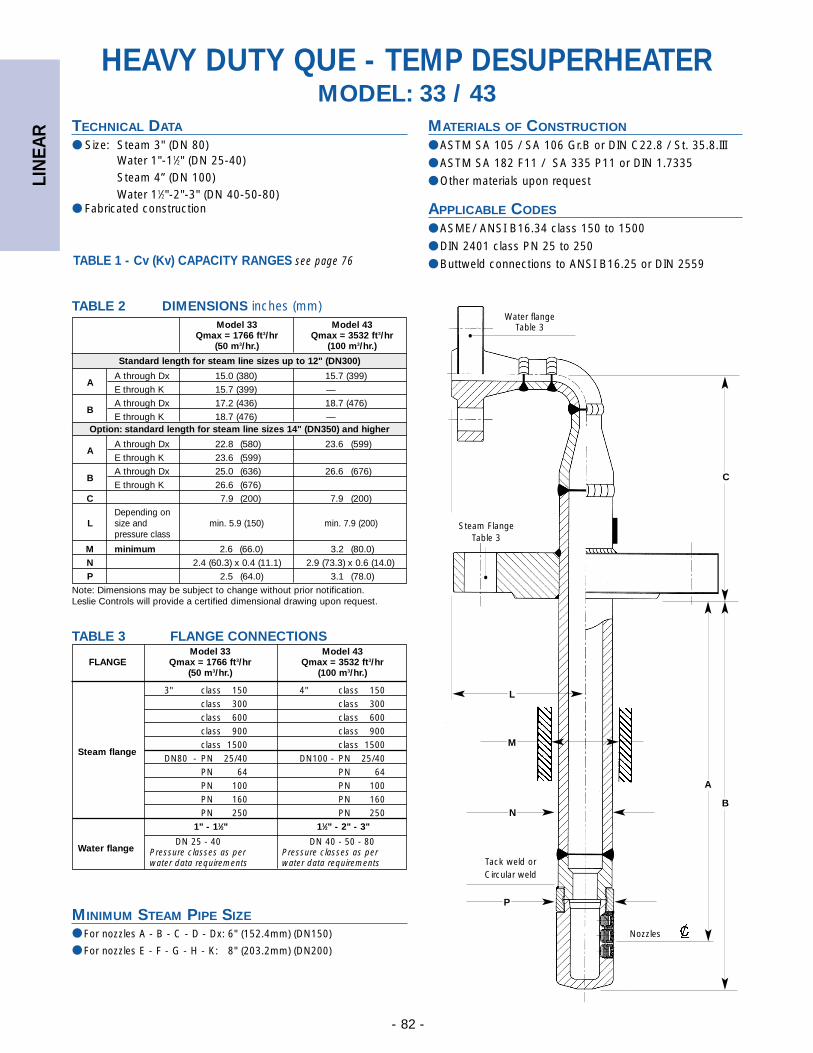
Model 33 Model 43Qmax = 1766 ft3/hr Qmax = 3532 ft3/hr
(50 m3/hr.) (100 m3/hr.)
Standard length for steam line sizes up to 12" (DN300)
AA through Dx 15.0 (380) 15.7 (399)
E through K 15.7 (399) —
BA through Dx 17.2 (436) 18.7 (476)
E through K 18.7 (476) —Option: standard length for steam line sizes 14" (DN350) and higher
AA through Dx 22.8 (580) 23.6 (599)
E through K 23.6 (599)
BA through Dx 25.0 (636) 26.6 (676)
E through K 26.6 (676)
C 7.9 (200) 7.9 (200)
Depending on L size and min. 5.9 (150) min. 7.9 (200)
pressure class
M minimum 2.6 (66.0) 3.2 (80.0)
N 2.4 (60.3) x 0.4 (11.1) 2.9 (73.3) x 0.6 (14.0)
P 2.5 (64.0) 3.1 (78.0)
Note: Dimensions may be subject to change without prior notification. Leslie Controls will provide a certified dimensional drawing upon request.
Model 33 Model 43FLANGE Qmax = 1766 ft3/hr Qmax = 3532 ft3/hr
(50 m3/hr.) (100 m3/hr.)
3" class 150 4" class 150class 300 class 300class 600 class 600class 900 class 900class 1500 class 1500
Steam flangeDN80 - PN 25/40 DN100 - PN 25/40
PN 64 PN 64PN 100 PN 100PN 160 PN 160PN 250 PN 250
1" - 11⁄2" 11⁄2" - 2" - 3"
DN 25 - 40 DN 40 - 50 - 80Water flange Pressure classes as per Pressure classes as per
water data requirements water data requirements
MINIMUM STEAM PIPE SIZE● For nozzles A - B - C - D - Dx: 6" (152.4mm) (DN150)
● For nozzles E - F - G - H - K: 8" (203.2mm) (DN200)
TABLE 2 DIMENSIONS inches (mm)
TABLE 3 FLANGE CONNECTIONS
MATERIALS OF CONSTRUCTION
● ASTM SA 105 / SA 106 Gr.B or DIN C22.8 / St. 35.8.III
● ASTM SA 182 F11 / SA 335 P11 or DIN 1.7335
● Other materials upon request
APPLICABLE CODES
● ASME/ ANSI B16.34 class 150 to 1500
● DIN 2401 class PN 25 to 250
● Buttweld connections to ANSI B16.25 or DIN 2559
HEAVY DUTY QUE - TEMP DESUPERHEATERMODEL: 33 / 43
TECHNICAL DATA
● Size: Steam 3" (DN 80)Water 1"-11⁄2" (DN 25-40)Steam 4” (DN 100)Water 11⁄2"-2"-3" (DN 40-50-80)
● Fabricated construction
Water flangeTable 3
Steam FlangeTable 3
Tack weld orCircular weld
Nozzles
•
•
B
C
L
M
N
A
P
TABLE 1 - Cv (Kv) CAPACITY RANGES see page 76

LIN
EAR
- 83 -
MATERIALS OF CONSTRUCTION
● ASTM SA 182 F22 or DIN 1.7380
● ASTM SA 182 F347H or DIN 1.4550
● ASTM SA 182 F91 or DIN 1.4903
● Other materials upon request
APPLICABLE CODES
● ASME/ ANSI B16.34 class 900 to 2500
● DIN 2401 class PN 160 to 400
● Butt weld connections to ANSI B16.25 or DIN 2559
HEAVY DUTY A.T. - TEMP DESUPERHEATERMODELS 13 / 23
TECHNICAL DATA
● Size: Steam 3" (DN80)
Water 1"-11⁄2" (DN25-40)Steam 4” (DN100)Water 11⁄2"-2"-3" (DN40-50-80)
● Forged construction
Water flangeTable 3
D
Steam Flange
Table 3
Circular weld
Nozzles
L
M
N
A
B
C
Model 13 Model 23Qmax = 1766 ft3/hr Qmax = 3532 ft3/hr
(50 m3/hr.) (100 m3/hr.)
Standard length for steam line sizes up to 12" (DN300)
AA through Dx 15.0 (380) 15.7 (399)
E through K 15.7 (399) —
BA through Dx 17.2 (436) 18.7 (476)
E through K 18.7 (476) —
C 7.9 (200) 7.9 (200)
D 12.0 (305) 14.0 (355)
Depending on L size and 5.9 (150) 7.9 (200)
pressure class
M minimum 2.6 (66.0) 3.2 (80.0)
N 2.4 (60.3) x 0.5 (12.6) 2.9 (73.3) x 0.6 (14.0)
Note: Dimensions may be subject to change without prior notification. Leslie Controls will provide a certified dimensional drawing upon request.
Model 13 Model 23FLANGE Qmax = 1766 ft3/hr Qmax = 3532 ft3/hr
(50 m3/hr.) (100 m3/hr.)
3" class 900 4" class 900class 1500 class 1500class 2500 class 2500
Steam flangeDN80 - PN 160 DN100 - PN 160
PN 250 PN 250PN 320 PN 320PN 400 PN 400
1" - 11⁄2" 11⁄2" - 2" - 3"
DN 25 - 40 DN 40 - 50 - 80Water flangePressure classes as per Pressure classes as per water data requirements water data requirements
MINIMUM STEAM PIPE SIZE● For nozzles A - B - C - D - Dx: 6" (152.4mm) (DN150)
● For nozzles E - F - G - H - K: 8" (203.2mm) (DN200)In case of smaller pipe size, please consult Leslie Controls.
TABLE 2 DIMENSIONS inches (mm)
TABLE 3 FLANGE CONNECTIONS
TABLE 1 - Cv (Kv) CAPACITY RANGES see page 76

LIN
EAR
- 84 -
SMALL PIPE INLINEDESUPERHEATER (SPID)
MODEL: 88
TECHNICAL DATA
● Size: Steam 11⁄2" - 4" (DN40 - DN100)Water 1/2" - 1" (DN15 - DN25)
MATERIALS OF CONSTRUCTION
● ASTM SA 182 F11 / SA 335 P11 or DIN 1.7335
● Other materials upon request
APPLICABLE CODES
● ASME/ ANSI B16.34 class 150 to 600
● DIN 2401 class PN16 to PN100
● Butt weld connections to ANSI B16.25 or DIN 2559
● Fabricated construction
● Special design for small steam lines with minimalsteam pressure losses
● Steam control within 43ºF (6°C) of saturationtemperature and ± 1% of controller range
● Venturi type vena contracta
● Wide range of Cv (Dv) capacities
APPLICATIONS
● Turbine gland sealing,
● Air ejectors,
● Nox steam for gas turbines,
● House steam,
● Drum dryers,
● Tire molds,
● Vulcanizing equipment and cooking kettles
SMALL PIPE INLINE DESUPERHEATER ORDERING CODE
8 A 1 5 0 F 0 0 0 B 1 1 5 0 F C E
1 2 3 4 5 6 7 8 9 10 11 12 13 14 15 16 17
Class Standard Body Rating End Connection Body Cv Con- Water Flange Rating Water ApprovalsSize nection Connection
Body Size - Position 10B = 11⁄2" (15mm)C = 2" (50mm)D = 3" (80mm)E = 4" (100mm)
Cv Connections - Position 111 = Cv from Capacity Table2 = Cv from Capacity Table3 = Cv from Capacity Table4 = Cv from Capacity Table5 = Cv from Capacity Table6 = Cv from Capacity Table7 = Cv from Capacity Table8 = Cv from Capacity Table
Class - Position 18 = Series 80000
Standard - Position 2A = ANSI
Body Rating - Position 3 - 5150 = Class 150300 = Class 300600 = Class 600
End Connections - Position 6 - 9F000 = FlangedW040 = Butt Weld End Sch 40W080 = Butt Weld End Sch 80W100 = Butt Weld End Sch 100W120 = Butt Weld End Sch 120W160 = Butt Weld End Sch 160
Water Flange Rating* - Position 12 - 14150 = Class 150300 = Class 300600 = Class 600
Water Connection - Position 15F = Raised face flange Wafer ConnectionX = Other
Approvals - Position 16 & 17CE = European Approvals
* Wafer flanged ends to be equal to or greater then body rating.

LIN
EAR
- 85 -
Apart from the spray quality of the atomizer (pri-mary atomization) there are other systemparameters which influence the Desuperheaterstations performance. These are:
Water to Steam RatioThis ratio is determined by dividing Gw by Gst = 6 : 1. Above this ratio, proper evaporation of theinjection water cannot always be guaranteed.In case of doubt, consult Leslie Controls.
Ordering / sizing data
Important system parameters
Distance to SensorThe distance from the SPID Desuperheater tothe temperature sensor should be 40 to 50 feet(12 to 15 meters), although the distance specificto the application is advised by Narvik at theenquiry stage. Longer distances will ensure thatfull evaporation of the water will take place atlower velocities.
Required Straight Pipe RunThe minimum pipe run, required downstream,varies with each individual application and isspecified by Narvik at the enquiry stage. Thisstraight run is needed to prevent erosion due toimpingement of water droplets against pipewalls, valves and fittings.Upstream straight run is normally 6 x D and thedownstream straight run 20 x D, as a minimum.
For applications outside these limitations, consult Leslie Controls or your local representative.
SMALL PIPE INLINE DESUPERHEATER (SPID)MODEL: 88
Steam Desuperheaters are selectedspecifically against application data. Foroptimal sizing, the following comprehensivedata should always be supplied.
Water DataWater pressure psi barWater temperature ºF ºC
Steam DataInlet pressure psi barInlet temperature ºF ºCOutlet temperature ºF set point ºC set point Steam flow max. lb / hr t / hrSteam flow normal lb / hr t / hrSteam flow min. lb / hr t / hr
GeneralPipe size inch mmPipe scheduleApplicationNarvik does recommend a strainer with amesh size of approx. 100 µ in the watersupply line to protect the SPIDDesuperheater from clogging.
Body Size Ports 1 2 3 4 5 6 7 8
B 1 1/2" Cv = 0.015 0.030 0.045 0.060 0.075 0.090
DN40 Kv = 0.013 0.026 0.039 0.052 0.065 0.078
C 2” Cv = 0.030 0.060 0.090 0.120 0.150 0.180
DN50 Kv = 0.026 0.052 0.078 0.104 0.130 0.156
D 3” Cv = 0.050 0.100 0.150 0.200 0.250 0.300 0.350 0.400
DN80 Kv = 0.043 0.086 0.129 0.172 0.215 0.258 0.302 0.345
E 4” Cv = 0.100 0.200 0.300 0.400 0.500 0.600 0.700 0.800
DN100 Kv = 0.086 0.172 0.258 0.344 0.430 0.516 0.602 0.688
SPID Cv (Kv) STANDARD CAPACITY RANGES
hwGw
Sizing formula
Every desuperheating station is a mixingpoint where there is a heat and massbalance.The universal formula is:
Gw = Gst ( h1-h2 ) : ( h2-hw )
In which:Gw = Injection water massGst = Inlet steam massh1 = Enthalpy of the inlet steamh2 = Enthalpy of the outlet steamhw = Enthalpy of the injection water
This formula enables calculation of thequantity of water required to lower the inletsteam temperature to the set - pointtemperature of the outlet steam.
h2Gst + Gw
h1Gst

LIN
EAR
- 86 -
Body Water Connections
Steam Rating
Size Weight ANSI DIN Connections A B Size ANSI DIN
RF (wafer)19⁄16 77⁄8 1/2(40) (200) (15) PN
11⁄2 6.0 Class PNBW sched. 40
23⁄8 83⁄32flanged
Class 150, 16, 40, 64,(40) (2.7) 150, 300, 600 6, 40, 64, 100 (60) 300 or 600 100
BW sched. 8023⁄8 89⁄16
RF(60)
RF (wafer)19⁄16 855⁄64 1/2(40) (202) (15) PN
2 8.2 Class PNBW sched. 40
29⁄16 93⁄32flanged
Class 150, 16, 40, 64,(50) (3.7) 150, 300, 600 16, 40, 64, 100 (65) 300 or 600 100
BW sched. 8029⁄16 93⁄32
RF(65)
RF (wafer)131⁄32 929⁄64 1/2(50) (227) (15) PN
3 15.2 Class PNBW sched. 40
231⁄32 945⁄64flanged
Class 150, 16, 40, 64,(80) (6.9) 150, 300, 600 16, 40, 64, 100 (75) 300 or 600 100
BW sched. 80231⁄32 957⁄64
RF(75)
RF (wafer)23⁄8 103⁄64 1(60) (260) (25) PN
4 26.0 Class PNBW sched. 40
29⁄16 1019⁄64flanged
Class 150, 16, 40, 64,(100) (11.8) 150, 300, 600 16, 40, 64, 100 (90) 300 or 600 100
BW sched. 8029⁄16 1034⁄64
RF(90)
RF BW
FLOW
A
B
FLOW
A
SMALL PIPE INLINE DESUPERHEATER (SPID)MODEL: 88
DIMENSIONS inches (mm) and WEIGHTS pounds (kg)

LIN
EAR
- 87 -
VEN-TEMP DESUPERHEATERMODEL: 25
TABLE 2 DIMENSIONS inches (mm)
MATERIALS OF CONSTRUCTION
● ASTM SA 105, SA 182 F11 or SA 182 F22
● DIN C22.8, 1.7335 or 1.7380
● Other materials upon request
APPLICABLE CODES
● ASME / ANSI B16.34 class 150 to 2500
● DIN 2401 class PN 25 to 400
● Buttweld connections to ANSI B16.25 or DIN 2559
TECHNICAL DATA
● Size: Steam 11⁄2" to 16" (DN40 to DN400)
Water 11⁄2" to 2" (DN15 to DN50)● Forged construction
● Venturi nozzle type
● Low pressure loss over the desuperheater station
● Water pressures marginally above steam pressure
D = depends upon ‘vena contracta’
A B E
C
B E
11⁄2"/1⁄2" DN 40 / 15 127 150 156 170 156 170 178 170 178 185 203 1952"/1⁄2" DN 50 / 15 152 165 165 180 165 195 216 195 216 200 235 2103"/1" DN 80 / 25 190 200 210 215 210 230 241 230 267 255 305 2754"/1" DN 100 / 25 229 235 254 250 273 265 292 265 311 300 356 3356"/11⁄2" DN 150 / 40 279 300 318 345 356 355 381 355 394 390 483 4258"/11⁄2" DN 200 / 40 343 375 381 415 419 430 470 430 483 485 552 525
10"/2" DN 250 / 50 406 450 445 470 508 505 546 515 584 585 673 64012"/2" DN 300 / 50 483 515 521 530 559 585 610 585 673 - 762 -14"/2" DN 350 / 50 533 580 584 600 603 655 641 - 749 - - -16"/2" DN 400 / 50 597 660 648 670 686 - 705 - 829 - - -
Notes
• Dimensions may be subject to change without prior notification and depending to the standards (flanged - butt weld, etc.)• Other pressure classes upon request.• Narvik will provide an order related certified dimensional drawing upon request.
Connections Class PN Class PN Class PN Class PN Class PN Class PN150 25/40 300 64 600 100 900 160 1500 250 2500 320
A - B / C A - B / C Ø E Ø E Ø E Ø E Ø E Ø E

LIN
EAR
- 88 -
Size Standard capacity ranges
A Cv =0,0125 Kv =0,0108
B Cv = 0,0263 Kv = 0,0227
C Cv = 0,0507 Kv = 0,0437
D Cv = 0,0973 Kv = 0,0839
Dx Cv = 0,1927 Kv = 0,1661
E Cv = 0,3158 Kv = 0,2722
F Cv = 0,4720 Kv = 0,4069
G Cv = 1,0000 Kv = 0,8621
H Cv = 1,5567 Kv = 1,3420
K Cv = 2,2233 Kv =1,9164
Cv (Kv) CAPACITY RANGES
Definition
Kv = Q√ S.G.∆P
Important system parameters
Apart from the spray quality of the atomizer (primary atomization) there are other system parameters which influence the Desuperheater stationsperformance. These are:
Distance to sensorThe distance from the Ven-Temp Desuperheater to the temperature sensor should be 39 to 50 feet (12 to 15 meters), although the distancespecific to the application is advised by Narvik at the enquiry stage. Longer distances will ensure that full evaporation of the water will take place atlower steam velocities.
Required straight pipe run The minimum pipe run, required downstream, varies with each individual application and is specified by Narvik at the enquiry stage. This straightrun is needed to prevent erosion due to impingement of water droplets against pipewalls, valves and fittings. Upstream straight run is normally 5 x D and the outlet straight run 13 feet (4 meters), as a minimum.
For applications outside these limitations, consult Narvik or your local representative.
Spray water must be injected in the direction of the steam flow. Narvik always recommends a strainer with a mesh size of approx. 100 µ in the water supply line to protect the injection nozzle from clogging.
Steam DataInlet pressure psi (bar)Inlet temperature ºF (°C)Outlet temperature ºF (°C setpoint )Steam flow max. t/hrSteam flow normal t/hrSteam flow min. t/hr
Water DataWater pressure psi (bar)Water temperature ºF (°C)
GeneralPipe size inch (mm)Pipe schedule
Turndown ratioGst max. : Gst min. = 4 : 1It is essential not to over-specify the maximum quantity of steam and this rule applies generally to any Desuperheater selection.
Water / Steam ratioGst : Gw = 5 : 1Above this ratio, proper evaporation of the injection water cannot always be guaranteed.
Ordering / sizing data
The Ven-Temp Desuperheater works optimally under their design conditions. A minimumdifferential in static pressure is required to maintain the velocity at such a level that proper mixingof water and steam is achieved.
Other Cv/Kv values upon request
1" (2
5mm
)1/
2" (1
6mm
)

LIN
EAR
- 89 -
For use in small steam lines with minimal steam pressure losses. Steam control within 43ºF of saturation temp and +/- 1% of controller range. Water flange connection available 1/2”-1” size. Steam connection available in wafer or butt weld in 11⁄2” – 4” size.
Distance to Sensor: distance from injection point to temp sensor should be 40-50 ft. Systems operating at pressures above 362psi can have significantly less run to the sensor (consult factory).Required Straight Pipe Run: upstream straight pipe run is normally 6xD and the downstream straightpipe run 20xD, as a minimum. For other distance applications consult factory.Turndown ratio: normally 1:40. Ratio is determined by dividing “steam flow max” x “steam flow min”.
LESLIE MODEL SPIDDesuperheater Specification Form
12501 Telecom Drive · Tampa, Florida 33637(813) 978-1000 · FAX: (813)-978-0984
Project/Job _________________________________________ Data Sheet ________ of ________
Unit/Customer ______________________________________ Spec _____________________________________
P.O./LCO File #______________________________________ Tag_______________________________________
Item _______________________________________________ Dwg______________________________________
Contract____________________________________________ Service ___________________________________
MFR Serial# ________________________________________
CONTROL VALVE SPEC SHEET
QUESTIONS? CALL LESLIE CONTROLS @ (813) 978-1000 PLEASE FAX COMPLETED FORM TO: (813) 977-0174

LIN
EAR
- 90 -
LESLIE MODEL QTSteam Conditioning System Specification Form
Steam Conditions OUT:
Pres ________________
Temp _______________
Steam Pipe Date Inlet:
Size ________________
Schedule ___________
Steam Conditions IN:
Flow ______________
Pres ______________
Temp _____________
Connecting Water Flange:
Size _________
Class ________
Steam Flange:
Size _________
Class ________
Water Conditions IN:
Flow ______________
Pres ______________
Temp _____________
* Water flange positions
Choose one: ______________
Note: Spraywater must be injected in the directionof the steam flow. Select appropriate sprayhead flange position.
SteamLine
SteamFlow
Steam PressureReducing Valve QT Desuperheater
Distance Sensor:distance from injection point totemp sensor should be 40-50 ft.Systems operating at pressuresabove 362 psi can have significantly less run to the sensor (consult factory).
Required Straight Pipe Run:distance from injection point to firstpipe bend is also a function of steampressure, temp and nozzle size.Based on experience systems up to362 psi, 13-20 ft., is an acceptabledistance.
Turndown ratio:normally 18:1 and 27:1. Ratio isdetermined by dividing “steamflow max” x “Steam flow min”.
FP9 FP12 FP3 FP6
12501 Telecom Drive · Tampa, Florida 33637(813) 978-1000 · FAX: (813)-978-0984
Project/Job _________________________________________ Data Sheet ________ of ________
Unit/Customer ______________________________________ Spec _____________________________________
P.O./LCO File #______________________________________ Tag_______________________________________
Item _______________________________________________ Dwg______________________________________
Contract____________________________________________ Service ___________________________________
MFR Serial# ________________________________________
CONTROL VALVE SPEC SHEET
QUESTIONS? CALL LESLIE CONTROLS @ (813) 978-1000 PLEASE FAX COMPLETED FORM TO: (813) 977-0174

LIN
EAR
- 91 -
LESLIE MODEL ATSteam Conditioning System Specification Form
Steam Conditions IN:
Flow ______________
Pres ______________
Temp _____________
Water Conditions IN:
Pres ______________
Temp _____________
Steam Conditions OUT:
Pres ________________
Temp _______________
Steam Pipe Date Inlet:
Size ________________
Schedule ___________
Steam Pipe Date Inlet:
Size ________________
Schedule ___________
Steam Flange:
Size _________
Class ________
Connecting Water Flange:
Size _________
Class ________
* Water flange positions
Choose one: ______________
Note: Spraywater must be injected in the directionof the steam flow. Select appropriate sprayhead flange position.
SteamLine
SteamFlow
Steam PressureReducing Valve
AT Desuperheater
Use on medium/low pressure steamapplications. there is no water controlvalve.The AT desuperheater valve regulates the amount of injectionwater by varying the number of injection nozzles. This enables thewater pressure to remain constant,independent of the number of injection nozzles in operation.
Distance Sensor:distance from injection point totemp sensor should be 40-50 ft.Systems operating at pressuresabove 362 psi can have significantly less run to the sensor (consult factory).
Required Straight Pipe Run:distance from injection point to firstpipe bend is also a function of steampressure, temp and nozzle size.Based on experience systems up to362 psi, 13-20 ft., is an acceptabledistance.
Turndown ratio:normally 18:1 and 27:1. Ratio isdetermined by dividing “steamflow max” x “Steam flow min”.
FP9 FP12 FP3 FP6
12501 Telecom Drive · Tampa, Florida 33637(813) 978-1000 · FAX: (813)-978-0984
Project/Job _________________________________________ Data Sheet ________ of ________
Unit/Customer ______________________________________ Spec _____________________________________
P.O./LCO File #______________________________________ Tag_______________________________________
Item _______________________________________________ Dwg______________________________________
Contract____________________________________________ Service ___________________________________
MFR Serial# ________________________________________
CONTROL VALVE SPEC SHEET
QUESTIONS? CALL LESLIE CONTROLS @ (813) 978-1000 PLEASE FAX COMPLETED FORM TO: (813) 977-0174