Embed Size (px)
Citation preview
8/6/2019 1-Wireless Power Transmission
http://slidepdf.com/reader/full/1-wireless-power-transmission 1/1
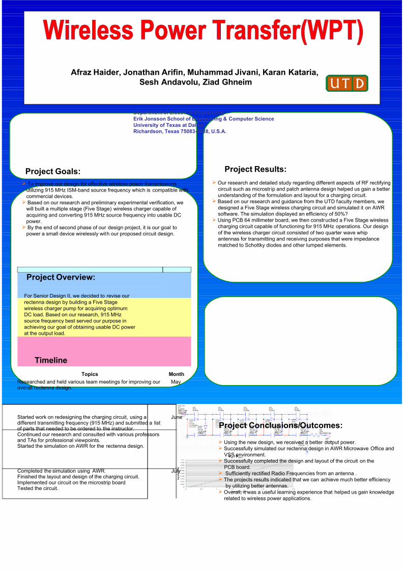
Afraz Haider, Jonathan Arifin, Muhammad Jivani, Karan Kataria,
Sesh Andavolu, Ziad Ghneim
Department of Electrical Engineering
Erik Jonsson School of Engineering & Computer Science
University of Texas at Dallas
Richardson, Texas 75083-0688, U.S.A.
Project Goals: Project Results:
Project Overview:
Project Conclusions/Outcomes:
To improve our design for effective wireless power transmissions
utilizing 915 MHz ISM-band source frequency which is compatible with
commercial devices.
Based on our research and preliminary experimental verification, we
will built a multiple stage (Five Stage) wireless charger capable of
acquiring and converting 915 MHz source frequency into usable DC
power. By the end of second phase of our design project, it is our goal to
power a small device wirelessly with our proposed circuit design.
For Senior Design II, we decided to revise our
rectenna design by building a Five Stagewireless charger pump for acquiring optimum
DC load. Based on our research, 915 MHz
source frequency best served our purpose in
achieving our goal of obtaining usable DC power
at the output load.
Timeline
Our research and detailed study regarding different aspects of RF rectifying
circuit such as microstr ip and patch antenna design helped us gain a better
understanding of the formulation and layout for a charging circuit.
Based on our research and guidance from the UTD faculty members, wedesigned a Five Stage wireless charging circuit and simulated it on AWR
software. The simulation displayed an efficiency of 50%? Using PCB 64 millimeter board, we then constructed a Five Stage wireless
charging circuit capable of functioning for 915 MHz operations. Our design
of the wireless charger circuit consisted of two quarter wave whip
antennas for transmitting and receiving purposes that were impedance
matched to Schottky diodes and other lumped elements.
Using the new design, we received a better output power. Successfully simulated our rectenna design in AWR Microwave Office and
VSS environment. Successfully completed the design and layout of the circuit on the
PCB board. Sufficiently rectified Radio Frequencies from an antenna . The projects results indicated that we can achieve much better efficiency
by utilizing better antennas. Overall, it was a useful learning experience that helped us gain knowledge
related to wireless power applications.
Topics Month
Researched and held various team meetings for improving our overall rectenna design.
May
Started work on redesigning the charging circuit, using adifferent transmitting frequency (915 MHz) and submitted a listof parts that needed to be ordered to the instructor.Continued our research and consulted with various professorsand TAs for professional viewpoints.Started the simulation on AWR for the rectenna design.
June
Completed the simulation using AWR.Finished the layout and design of the charging circuit.Implemented our circuit on the microstrip board.Tested the circuit.
July