Embed Size (px)
Citation preview

Wind Turbine Control 1
1 Wind Turbine Control
• The control system on a wind turbine is designed to:
1. seek the highest efficiency of operation that maximizes the
coefficient of power, Cp,
2. ensure safe operation under all wind conditions.
• Wind turbine control systems are typically divided into three
functional elements:
1. the control of groups of wind turbines in a wind farm,
2. the supervising control of each individual wind turbine, and
3. separate dedicated dynamic controllers for different wind tur-
bine sub-systems.
Figure 1: Schematic of the wind turbine functional control elements.
University of Notre Dame AME 40530

Wind Turbine Control 2
• The wind farm controller’s function is “power management”.
– It can initiate and shut down turbine operation as well as co-
ordinate the operation of numerous wind turbines in response
to environmental and operating conditions.
• The wind turbine supervisory controller manages the individual
turbine operation.
– Including power production, low-wind shutdown, high-wind
shutdown, high load limits, and orderly start-up and shut-
down
– Also provides control input to the dynamic controllers for
r.p.m. control to maintain an optimum tip-speed-ratio, and
blade pitch control.
University of Notre Dame AME 40530

Wind Turbine Control 3
Figure 2: Section view of typical components of a wind turbine that are involved in itsmonitoring and control.
University of Notre Dame AME 40530

Wind Turbine Control 4
• Generally, there exists an optimum tip-speed-ratio, λ that
maximized Cp.
– The exact λ depends on the individual wind turbine design
(6 ≤ λ ≤ 8)
Figure 3: Example of the relation between the rotor tip-speed ratio and rotor pitch angle onthe coefficient of power for a 600kW two-bladed horizontal wind turbine.
University of Notre Dame AME 40530

Wind Turbine Control 5
• The sensitivity of Cp to λ motivates closed-loop control focusing
on the the rotation frequency
Figure 4: Schematic of a wind turbine closed-loop control system.
University of Notre Dame AME 40530

Wind Turbine Control 6
1.1 Aerodynamic Torque Control
• One of the approaches to control λ is through control of the rotor
aerodynamic torque.
– This ultimately comes by controlling the rotor L/D.
• For L/D control, there are two approaches:
1. stall-regulated rotor designs
2. pitch regulated rotor designs
• Stall-regulated rotors are designed with section shapes and
mean angles of attack to cause the rotor to stall at higher wind
speeds, beginning at rated power wind speeds. (More detail on
this later)
• Pitch-regulated rotors reduce the aerodynamic torque by re-
ducing the pitch and thereby the local angle of attack of the rotor
sections.
– The lower angles of attack reduce the section lift coefficients
and thereby the aerodynamic torque on the rotor.
– The pitch control initiates when the wind velocity is sufficient
to generate the turbine rated power level.
– It continues to reduce the pitch to seek to maintain an opti-
mum λ while also maintaining a constant rated power up to
the cut-out wind speed.
University of Notre Dame AME 40530

Wind Turbine Control 7
1.2 Electrical Torque Control
• Another approach to control λ is through electrical torque con-
trol.
• Synchronous generators are most commonly used in large wind
turbines
• Synchronous machines are commonly used as generators espe-
cially for large power systems, such as turbine generators and
hydroelectric generators in the grid power supply.
• The reactive power generated by a synchronous machine can be
adjusted by controlling the magnitude of the rotor field current
unloaded synchronous machines are also often installed in power
systems solely for power factor correction, or for control of reac-
tive kV-A flow.
• For a general case of a synchronous machine with P poles, the
relationship between the electrical and mechanical angular ve-
locities, ω and ωm is
ω =P
2ωm. (1)
• In terms of physical frequency, f (Hz) and n (r.p.m),
n =120f
P. (2)
University of Notre Dame AME 40530

Wind Turbine Control 8
Figure 5: Schematic drawing of a 4-pole synchronous machine along with the sinusoidalwaveform of the induced electromotive force (emf) which has units of volts, that is producedby the rotation of the rotor.
• Most wind turbine generators have 4 poles.
• To produce the 60 Hz. frequency that is the U.S. power standard,
the rotor would need to spin at 1800 r.p.m!
University of Notre Dame AME 40530

Wind Turbine Control 9
• For a fixed r.p.m. wind turbine, a gear box would be designed so
that at the optimum tip-speed ratio, the generator rotor would
spin at the r.p.m. that would produce 60 Hz.
– This approach is quite restrictive
• An alternate approach is converting the AC power to DC power,
after which it is converted back to AC power with the U.S. stan-
dard 60 Hz frequency.
University of Notre Dame AME 40530

Wind Turbine Control 10
2 Wind Turbine Operation Strategy
• Four strategic objectives to wind turbine operation:
1. to maximize energy production while keeping operation within
speed and load constraints,
2. to prevent extreme loads and to minimize fatigue damage
that can occur as a result of repeated bending caused by
weight on the rotors and unsteady aerodynamics loads,
3. to provide acceptable power quality at the point of connec-
tion to the power grid, and
4. to provide safe operation.
• The control approach depends on the wind turbine design:
1. For (Ucut−in < U∞ < Urated) the object is to maximize power
production.
2. For (Urated < U∞ < Ucut−out) the object is to limit power to
the rated value.
• Two approaches to accomplish this:
1. Fixed Speed Designs
2. Variable Speed Designs
University of Notre Dame AME 40530
Wind Turbine Control 11
2.1 Fixed Speed Designs
• Fixed speed designs fall under two categories:
1. Stall Regulated
2. Active Pitch Regulated
• With Stall Regulated Fixed Speed Control, the rotor
blades are at a fixed pitch angle and are designed to stall at
Urated to passively regulate the generated power.
– They are designed to operate near the optimum tip-speed
ratio below Urated.
– As the wind speed increases, the effective angle of attack of
the rotor sections, α, increases, e.g.:
α = φ− [θT + θcp] (3)
University of Notre Dame AME 40530

Wind Turbine Control 12
– Now φ is given by
φ = tan−1 1− a1 + a′
U∞Ωr
= tan−1
1− a(1 + a′)λr
(4)
– For fixed θT and θcp, α, is only a function of φ.
– For a constant, λ = λoptimum, and near optimum power co-
efficient, a ' 1/3 and a′ ' 0,
α ' φ ∼ tan−1 (U∞) (5)
• Therefore there is a direct link between the effective angle of
attack and the free-stream wind speed.
• When α ≥ αstall, L/D will decrease resulting in a decrease in
the aerodynamic torque and generated power
• This is the fundamental mechanism of passive stall regu-
lated fixed speed control.
University of Notre Dame AME 40530

Wind Turbine Control 13
• With Active Pitch Regulated Fixed Speed Control,
the blade pitch is changed to provide power smoothing in high
wind conditions.
– For U∞ < Urated, the blade pitch is kept fixed.
– This is the chosen approach to limit the pitch mechanism
wear.
– At U∞ = Urated, the blade pitch is dynamically varied to
seek to hold a constant power level.
– At U∞ ≥ Ucut−out, the blade is pitched to a position that
minimized the rotor aerodynamic torque.
– Mechanical or electrical/reactive breaking is sometimes used
to further prevent rotor rotation above Ucut−out.
University of Notre Dame AME 40530

Wind Turbine Control 14
2.2 Variable Speed Designs
• Variable speed designs utilize electrical torque control to seek to
optimize λoptimum.
• This is applied to both stall regulated and active pitch
regulated appoaches.
• With Stall Regulated Variable Speed Control
– For U∞ < Urated, variable speed control is used to maintain
the optimum tip-speed ratio, seeking to maximize Cp.
– For U∞ = Urated, Ω is decreased and the rotor blades are
allowed to stall.
Figure 6: Power curve for a stall regulated wind turbine with variable speed design.
University of Notre Dame AME 40530

Wind Turbine Control 15
• With Active Pitch Regulated Variable Speed Control
– For U∞ < Urated, the blade pitch is fixed, and variable speed
control is used to maintain the optimum tip-speed ratio, seek-
ing to maximize Cp.
– For U∞ = Urated, the generator torque is used to maintain
constant power, pitch control is used to regulate the rotor
r.p.m., seeking to maintain the optimum tip-speed ratio.
University of Notre Dame AME 40530

Wind Turbine Control 16
• Consider a control scheme for Variable Speed Adaptive
Torque Control
• Object to maximize energy capture between Ucut−in ≤ U∞ ≤Urated using variable speed, torque control
• It can be shown that the rotor inertial, Ω is
Ω =1
2JρAR3Ω2
Cpλ3− Cpmax
λ3opt
. (6)
where J is the inertial of the rotor.
• If Cpmax is known apriori, then
1. if λ > λopt then Ω < 0 and the rotor needs to decelerate
towards λ = λopt
2. if λ < λopt then Ω > 0 and the rotor needs to accelerate
towards λ = λopt.
• Therefore Cp = (Cpmax/λ3opt)λ
3 is the control trajectory.
University of Notre Dame AME 40530

Wind Turbine Control 17
Figure 7: Example of control trajectory to seek the optimum tip-speed ratio for the windturbine performance shown in Figure 3 with β = −1.
University of Notre Dame AME 40530

Wind Turbine Control 18
3 Axial Induction Control
• Standard control of wind turbines has focused on changing the
pitch of the rotor and control of the rotor RPM in order to
maintain an λ.
• Standard practice is to have a fixed pitch angle for Region II
wind speeds
• The fixed pitch in Region II wind speeds is intended to maximize
the average efficiency from Ucut−in to Urated
• However, with a rigid rotor, the optimum (Betz) efficiency is
generally only approached at a single wind speed, and As a result,
performance falls short of optimum.
Figure 8: Generic power curve for a wind turbine illustrating optimum (Betz) and actualperformance in Region II.
University of Notre Dame AME 40530

Wind Turbine Control 19
• Following the BEM analysis, the differential torque produced by
radial segment of the rotor at radius, r, is
dQ = 4πρU∞(Ωr)a′(1−a)r2dr− 1
2ρW 2NcCd cos(φr)rdr. (7)
• The second term in Equation 7 represents the aerodynamic drag.
• As long as α < αstall, we can neglect the drag, therefore
dQ = 4πρU∞(Ωr)a′(1− a)r2dr. (8)
• Substituting for a′ in terms of a
dQ = 4πρU 2∞a(1− a)2r2
λdr. (9)
• Assuming constant wind conditions (ρ and V∞) and constant λ,
dQ = C1a(1− a)2r2dr. (10)
or
Q ∝ a(1− a)2. (11)
• In terms of the aerodynamic power,
Paero = QΩ = Paero ∝ a(1− a)2 ∝ A. (12)
University of Notre Dame AME 40530

Wind Turbine Control 20
Figure 9: Plot of A = a(1− a)2 versus a showing that the maximum occurs at a = 1/3.
Figure 10: Plot of percent improvement obtained by optimizing the axial induction factor.
University of Notre Dame AME 40530
Wind Turbine Control 21
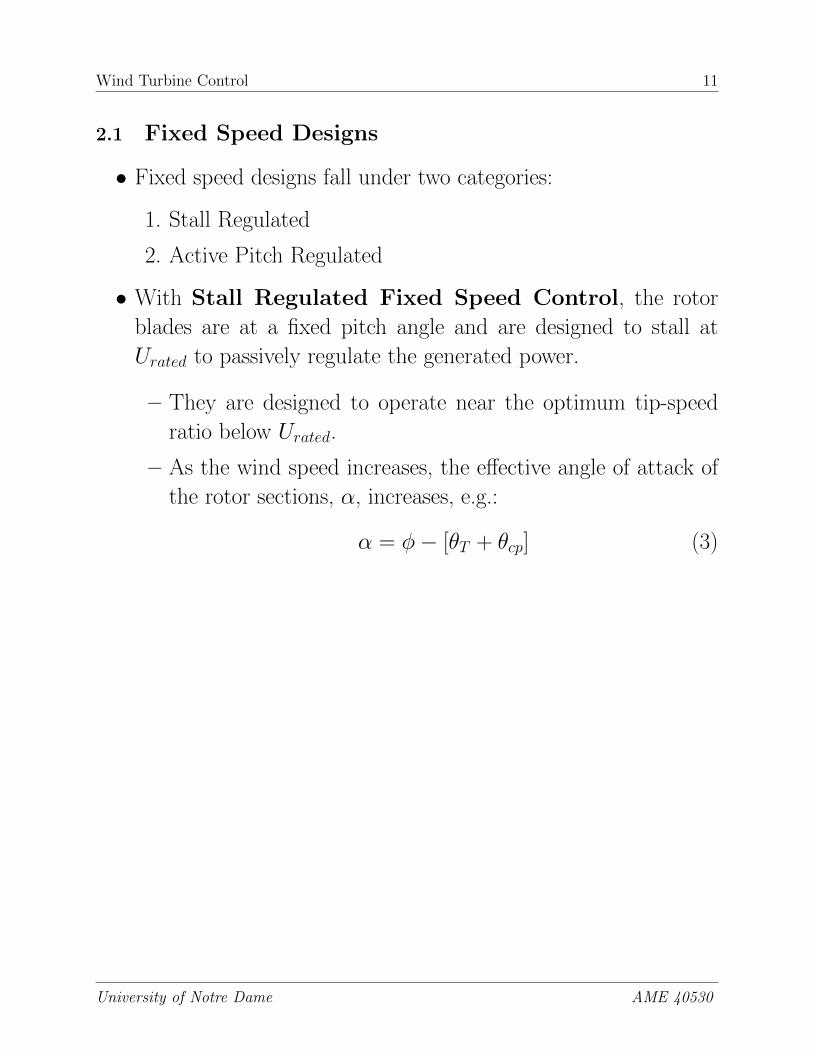
Figure 11: Plot of the rotor radial distribution of the axial induction factor for three tipspeed ratios of an existing current-generation wind turbine.
University of Notre Dame AME 40530

Wind Turbine Control 22
Figure 12: Plot of the rotor radial distribution of the lift coefficient for three tip speed ratiosof an existing current-generation wind turbine.
Figure 13: Plot of the rotor radial distribution of the lift coefficient that for which the axialinduction factor is the ideal 1/3 for three tip speed ratios of an existing current-generationwind turbine.
University of Notre Dame AME 40530

Wind Turbine Control 23
Figure 14: Plot of the rotor radial distribution of the change needed in the lift coefficient toachieve the ideal 1/3 axial induction factor for three tip speed ratios of an existing current-generation wind turbine.
• Example: A wind farm rated at 100 MW (approximately 65
1.5 MW wind turbines) and operating with a reasonable 35%
capacity factor can produce about 307 GWh of energy in a given
year.
– If the cost of energy is $0.04 per kWh, each GWh is worth
about $40,000
– Therefore a 1% loss of energy on this wind farm is equivalent
to a loss of $123,000 per year.
– A 4% improvement in the power would result in approxi-
mately $500K profit for the wind farm.
University of Notre Dame AME 40530

Wind Turbine Control 24
Lift Control
• Lift control techniques that have been developed for general air-
foils can be applied to wind turbine rotors. These include
1. plane trailing edge flaps
2. split trailing edge flaps
3. Gurney flaps
4. trailing edge blowing
5. plasma actuators
Figure 15: Comparison of the performance of different active lift control approaches.
University of Notre Dame AME 40530

Wind Turbine Control 25
• Plane and split trailing edge flaps have the same effect
as changing the camber of an airfoil.
Figure 16: Lift as a function of angle of attack (left) and drag polar (right) for a zero camberairfoil (solid curve) and with a plane trailing edge flap with downward deflection (dashedcurve).
Figure 17: Illustration of spanwise segmented flaps.
University of Notre Dame AME 40530

Wind Turbine Control 26
Figure 18: Illustration of spanwise segmented piezo-actuator controlled flaps.
University of Notre Dame AME 40530

Wind Turbine Control 27
• A variation on a split flap is a Gurney flap.
• A Gurney flap on the lower (pressure) surface will produce pos-
itive lift
• A Gurney flap on the upper (suction) surface will produce neg-
ative lift
• The general rule of thumb for Gurney flaps is that their height
should range between 1% to 1.5% of the airfoil chord length, and
that their position should be from 0% to 10% of the chord length
from the trailing edge of the airfoil.
• The largest effect occurs when the Gurney flap is placed at the
exact trailing edge.
Figure 19: Illustration of a Gurney flap for lift control.
University of Notre Dame AME 40530
Wind Turbine Control 28
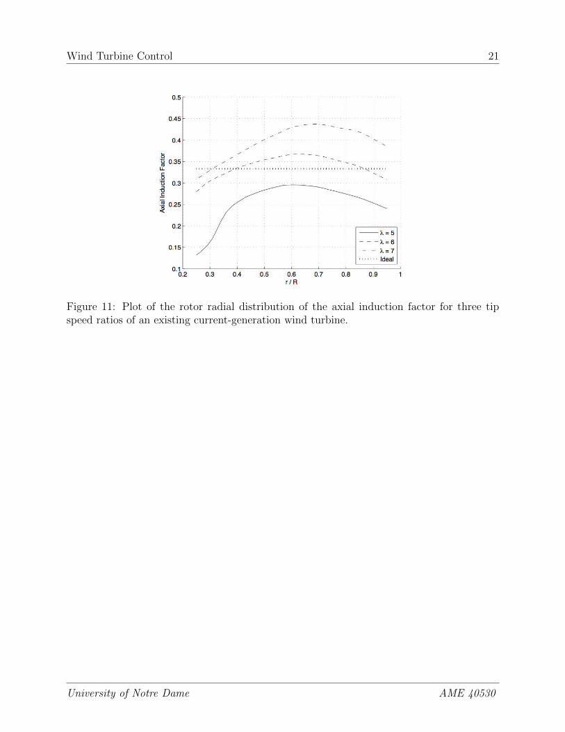
Figure 20: Illustration of multiple spanwise Gurney flaps for spanwise varying lift control.(From VanDam
University of Notre Dame AME 40530

Wind Turbine Control 29
• Variable geometry section shapes
Figure 21: Flexsys flexible airfoil.
Figure 22: Flexsys flexible airfoil.
University of Notre Dame AME 40530

Wind Turbine Control 30
• Circulation control
Figure 23: Circulation control airfoil.
Figure 24: Leading and trailing-edge blowing airfoil.
University of Notre Dame AME 40530

Wind Turbine Control 31
• Plasma actuators
Figure 25: Plasma actuator schematic.
University of Notre Dame AME 40530

Wind Turbine Control 32
Figure 26: TE plasma actuator effect.
• Rotor tip extensions
University of Notre Dame AME 40530

Wind Turbine Control 33
Figure 27: Rotor tip extensions.
Figure 28: Rotor tip extensions.
University of Notre Dame AME 40530