Embed Size (px)
Citation preview

1
VISWAS and On Diagnosability with IEEE P1522 and UML2.0 Testing Profile
Dr Sita RamakrishnanSchool Computer Science & Software
EngineeringMonash University, [email protected]
2FATES2003, 6FATES2003, 6thth Oct 2003 Oct 2003
OverviewOverview
A Test Method for Validating Interoperable Distributed Software & Systems (VISWAS)
From Testability to Diagnosability Aspects UML2.0 Testing Profile IEEE Std P1522 Testability and Diagnosability with industry
standards Further Work
3FATES2003, 6FATES2003, 6thth Oct 2003 Oct 2003
VISWAS
Is a test method developed for validating interoperable distributed software & systems
Extends UML models to include testability aspects with design by contract notions
Automated test sequence generation is produced from the extended message sequence charts and Live State Charts with temporal action propagation list
More detailed look at VISWAS next

4FATES2003, 6FATES2003, 6thth Oct 2003 Oct 2003
A Generic Test Environment
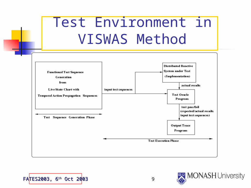
3 main aspects to the test environment: The test model, which is the application model augmented
to include testing requirements by adding application specific constraints to the component interface protocol
The test model (state model) fed to the test design software. This software tool uses the critical properties of testing requirements built in the test model to generate automated test sequences
The test execution phase is the diagnosis phase. Accepts test inputs from SUT, and test is evaluated as pass or fail.

5FATES2003, 6FATES2003, 6thth Oct 2003 Oct 2003
A Generic Test Environment
6FATES2003, 6FATES2003, 6thth Oct 2003 Oct 2003
Modelling layers of the VISWAS architecture
To create a customised process suited to the testing requirements of distributed software systems
Representational layer – used to model the given concurrent/distributed system to be tested
Assertional layer – used to represent the dynamic model with state machines & MSCs; include temporal properties explicitly to capture safety & liveness requirements for distributed component testing
Tool layer – used to develop software testing tools – e.g. automate test sequence generation in VISWAS
7FATES2003, 6FATES2003, 6thth Oct 2003 Oct 2003
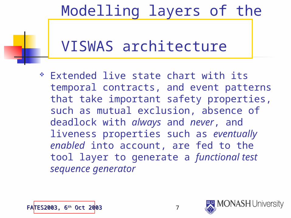
Modelling layers of the VISWAS architecture
Extended live state chart with its temporal contracts, and event patterns that take important safety properties, such as mutual exclusion, absence of deadlock with always and never, and liveness properties such as eventually enabled into account, are fed to the tool layer to generate a functional test sequence generator

8FATES2003, 6FATES2003, 6thth Oct 2003 Oct 2003
Modelling layers in VISWAS test method
9FATES2003, 6FATES2003, 6thth Oct 2003 Oct 2003
Test Environment in VISWAS Method
10FATES2003, 6FATES2003, 6thth Oct 2003 Oct 2003
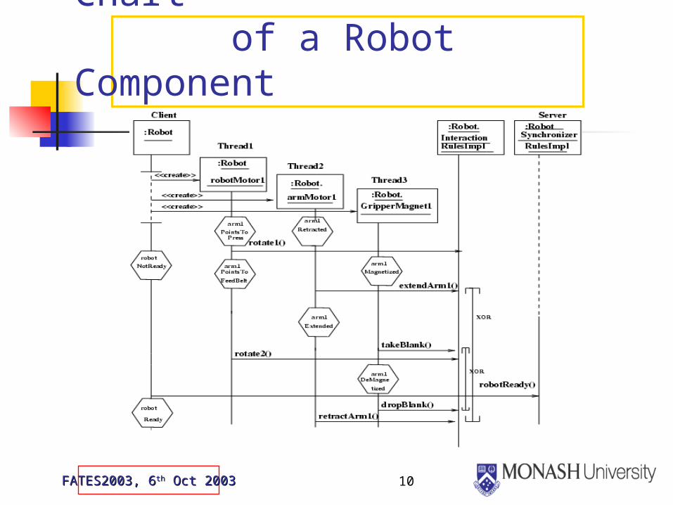
Message Sequence Chart of a Robot Component
11FATES2003, 6FATES2003, 6thth Oct 2003 Oct 2003
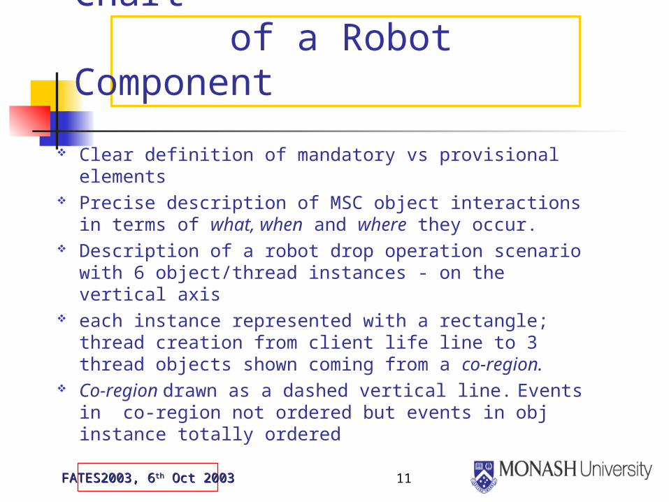
Message Sequence Chart of a Robot Component
Clear definition of mandatory vs provisional elements
Precise description of MSC object interactions in terms of what, when and where they occur.
Description of a robot drop operation scenario with 6 object/thread instances - on the vertical axis
each instance represented with a rectangle; thread creation from client life line to 3 thread objects shown coming from a co-region.
Co-region drawn as a dashed vertical line. Events in co-region not ordered but events in obj instance totally ordered

12FATES2003, 6FATES2003, 6thth Oct 2003 Oct 2003
Message Sequence Chart of a Robot Component
A hexagon crossing over an instance represents the condition to be satisfied by the instance during execution. E.g. robotMotor1robotMotor1 thread must be in arm1PointstoPressarm1PointstoPress state at the start of this scenario
shared condition represented by hexagons crossing over 2 or more objects
A horizontal arrow means communication via message passing between 2 instances
server object shown with a dashed line to show existentiality - it need not be alive until all the thread events of the robot component object, rotate1(), extendArm1(), takeBlank(), rotate2() have happened

13FATES2003, 6FATES2003, 6thth Oct 2003 Oct 2003
Message Sequence Chart of a Robot Component
Two extensions to MSC notation were introduced a textual annotation - XOR to show mutual
exclusion a timeline shown as a solid line that stretches
between the 2 mutually exclusive methods. Timeline has a cap at the top & bottom of the line. Cap introduced to ensure clarity in the depiction of the scope of mutually exclusive methods
Aim was to integrate MSCs and statecharts in the development and testing process
14FATES2003, 6FATES2003, 6thth Oct 2003 Oct 2003
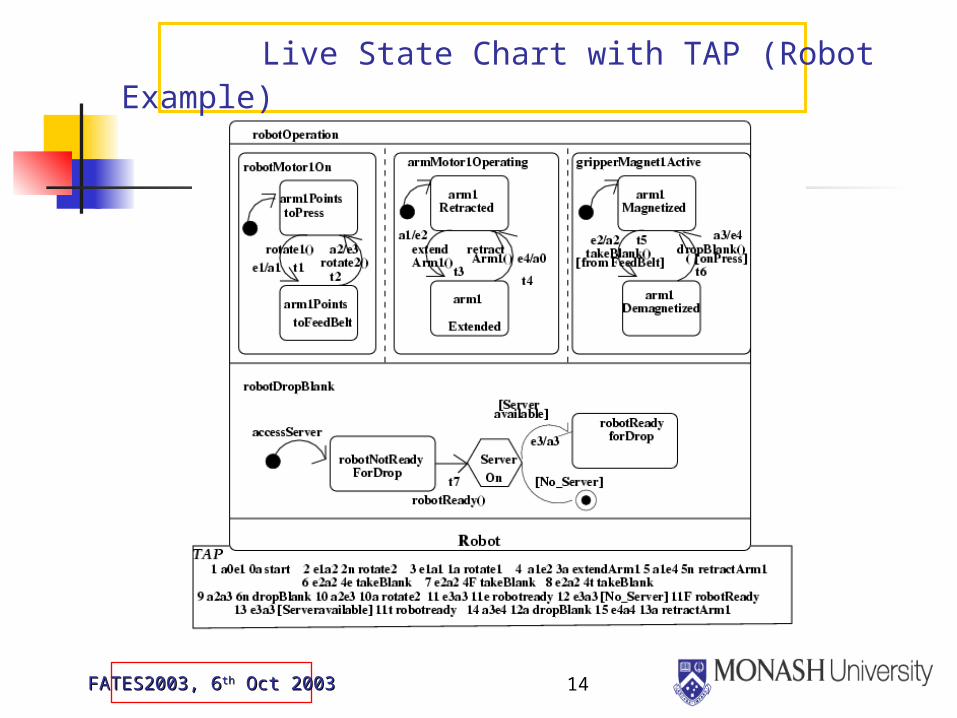
Live State Chart with TAP (Robot Example)
15FATES2003, 6FATES2003, 6thth Oct 2003 Oct 2003
Live State Chart with TAP (Robot Example)
Live State Chart (LSC)’s event activation sequences and extensions introduced in MSC to show mutual exclusion - used in LSC to introduce TAPTAP
Temporal operators with the formalism from TLA are shown explicitly with event/action sequences in LSC
In TAP, operators always (a) and never (n) for mutual exclusive methods represent safety properties
never (n) - not shown in the body of LSC but shown clearly in MSC with the mutual exclusion (always & never) - included in TAP as they are part of testing requirements

16FATES2003, 6FATES2003, 6thth Oct 2003 Oct 2003
Live State Chart with TAP (Robot Example)
Liveness properties are shown as eventuallyeventually (e) truetrue (t) or false false (F).
For an EventuallyEventually (e) constraint in LSC, both (t) and (f) are included in the TAP list to accommodate eventually trueeventually true and eventually eventually falsefalse conditions
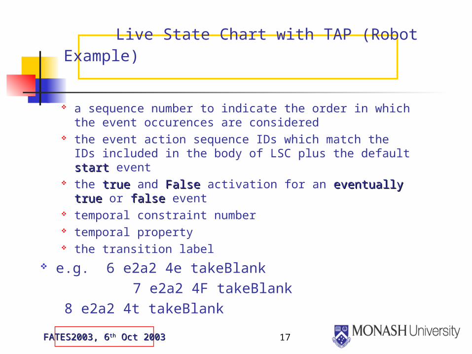
Live State Chart has the temporal action propagation (TAP) sequence list, which lists for each activation sequence:
17FATES2003, 6FATES2003, 6thth Oct 2003 Oct 2003
Live State Chart with TAP (Robot Example)
a sequence number to indicate the order in which the event occurences are considered
the event action sequence IDs which match the IDs included in the body of LSC plus the default startstart event
the truetrue and FalseFalse activation for an eventually trueeventually true or falsefalse event
temporal constraint number temporal property the transition label
e.g. 6 e2a2 4e takeBlank 7 e2a2 4F takeBlank
8 e2a2 4t takeBlank

18FATES2003, 6FATES2003, 6thth Oct 2003 Oct 2003
Event Pairs
19FATES2003, 6FATES2003, 6thth Oct 2003 Oct 2003
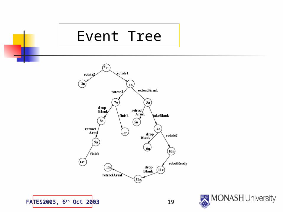
Event Tree
20FATES2003, 6FATES2003, 6thth Oct 2003 Oct 2003
Test Sequence Generation Phase
21FATES2003, 6FATES2003, 6thth Oct 2003 Oct 2003
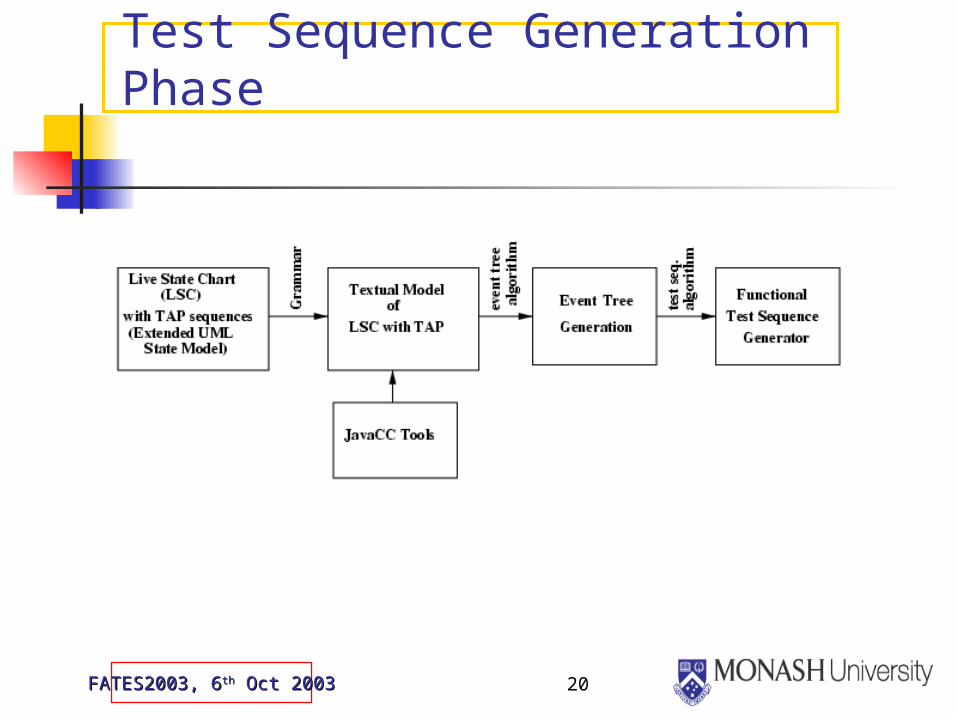
Test Sequence Generation Phase
Test sequence generation phase involves: Live State Chart (LSC) with Temporal action
propagation (TAP Sequences) Providing a Grammar for the LSC with TAP LSC transformed into an event tree using
JavaCC tools - specification model fed to JavaCC tools in the context of a Grammar
Deriving a prototype implementation tool (functional test sequence generator) for automating the test sequence generation from the event tree
22FATES2003, 6FATES2003, 6thth Oct 2003 Oct 2003
From Testability to Diagnosability aspects
Testability and diagnosability - related attributes – when building, measuring & predicting the correctness & robustness of software components
Testability viewed as software design quality attribute – Defined in IEEE std.610.12-1990 as “the degree to which a system or component facilitates the establishment of test criteria and the performance of tests to determine whether those criteria have been met”
Diagnosability is a wider notion than testability and encompasses finding information or explanation about the state of a system under test and includes faults & no faults

23FATES2003, 6FATES2003, 6thth Oct 2003 Oct 2003
From Testability to Diagnosability aspects
While testability is concerned with detecting faults, diagnosability aspect of testing is about isolating and pointing out fault locations to repair/correct them
View testing from 2 complementary objectives: conformance-directed when the intent is to achieve
conformance to requirement specification Fault-directed when the intent is to reveal faults
through failures Test oracle in a test environment (see slide 5) could be
expanded to provide detailed diagnostic information Detailed diagnosability models using IEEE Standard
P1522, UML 2.0 Test Profile, MSC2000 and TTCN-3 Graphical Notation

24FATES2003, 6FATES2003, 6thth Oct 2003 Oct 2003
UML 2.0 Testing Profile
UML models focused on system structure & behaviour, and no details provided for specifying test procedures & objectives
UML 2.0 testing profile (UTP) initiated in June 2001 by OMG to address this gap
Based on work on testing such as TTCN-3 UTP has the notion of test architecture, test
data and test behaviour Test architecture is a set of related classes &/or
components from which test cases can be specified

25FATES2003, 6FATES2003, 6thth Oct 2003 Oct 2003
UML 2.0 Testing Profile
The test data package contains data sent to system under test (SUT) & received from SUT
A test configuration contains the test components & the SUT
An arbiter is a test component aimed at separating test behaviour from test evaluation. Evaluates test results and assign verdicts of a test case
A verdict is the outcome of a test case being pass, fail, inconc or error as defined in TTCN-3
During the execution of a test case, a test trace is generated and stored in a test log

26FATES2003, 6FATES2003, 6thth Oct 2003 Oct 2003
IEEE Std P1522
The Artificial Intelligence Exchange and Service Tie to All Test Environments (AI-Estate) standards are product information standards for test and diagnosis
IEEE Std P1522 initiative got under way for standardising testability and diagnosability metrics. In P1522, diagnosability includes all aspects of fault detection, fault localization and fault identification
Diagnosability was not the focus of concern in VISWAS, and test execution phase of test env. in VISWAS was not automated
Exploring IEEE Std P1522 & UTP for modelling and automating the test execution phase of test environment in VISWAS

27FATES2003, 6FATES2003, 6thth Oct 2003 Oct 2003
Testability and Diagnosability with industry standards
The primary purpose of standardizing effort such as the AI-ESTATE for IEEE 1232 family & the standard on testability and diagnosability metrics, P15222 is to facilitate the development of diagnostic tools & systems that can be widely used
Integrated diagnostics conceptual model provided by Sheppard (see Ref. 21) provides direct ties to the testability & diagnosablity standard, P1522
The model depicts relationships between test requirements, tests & outcome
outcome is based on diagnostic rules with which conclusions are drawn with levels of confidence
diagnosis can point to failures or faults & corrective actions are taken

28FATES2003, 6FATES2003, 6thth Oct 2003 Oct 2003
Testability and Diagnosability with industry standards
Diagnostic components constructed according to standards facilitate competition in the market place in terms of risks, cost and quality.
Standards imply a maturity in the underlying technology, thus adding to the level of confidence
TTCN-3 is the only standardised language for the specification & implementation of test cases.
Graphical format for TTCN-3 (GFT) is based on MSCs & UML, and extends it with test specific concepts such as verdicts & defaults. GFT is the basis for the definition of UML 2.0 test profile
UML is a widely used industry standard for software component modelling. Makes sense to use UML 2.0 test profile for test description

29FATES2003, 6FATES2003, 6thth Oct 2003 Oct 2003
Further Work
Currently investigating various avenues for further work in this area. Some of the areas are:
building an automated test oracle (diagnostics tool) to capture diagnostics (pass/fail) status of test inputs from the automated test sequence generator
analysing the diagnostic information to measure the goodness of the design and effectiveness of test strategies using the above or existing diagnostic tools


![Contribution to the analysis of Discrete Event Systemspeople.rennes.inria.fr/Herve.Marchand/hdr.pdfUnification of various notions of diagnosability[Wodes06,Ifac08] Diagnosis of transient](https://img.dokumen.tips/doc/110x75/60b08726310042503b09dbb2/contribution-to-the-analysis-of-discrete-event-uniication-of-various-notions-of.jpg)