Embed Size (px)
Citation preview
1
Turbomachinery Lecture 4b
- Compressor / Engine Maps- Radial Turbine
2
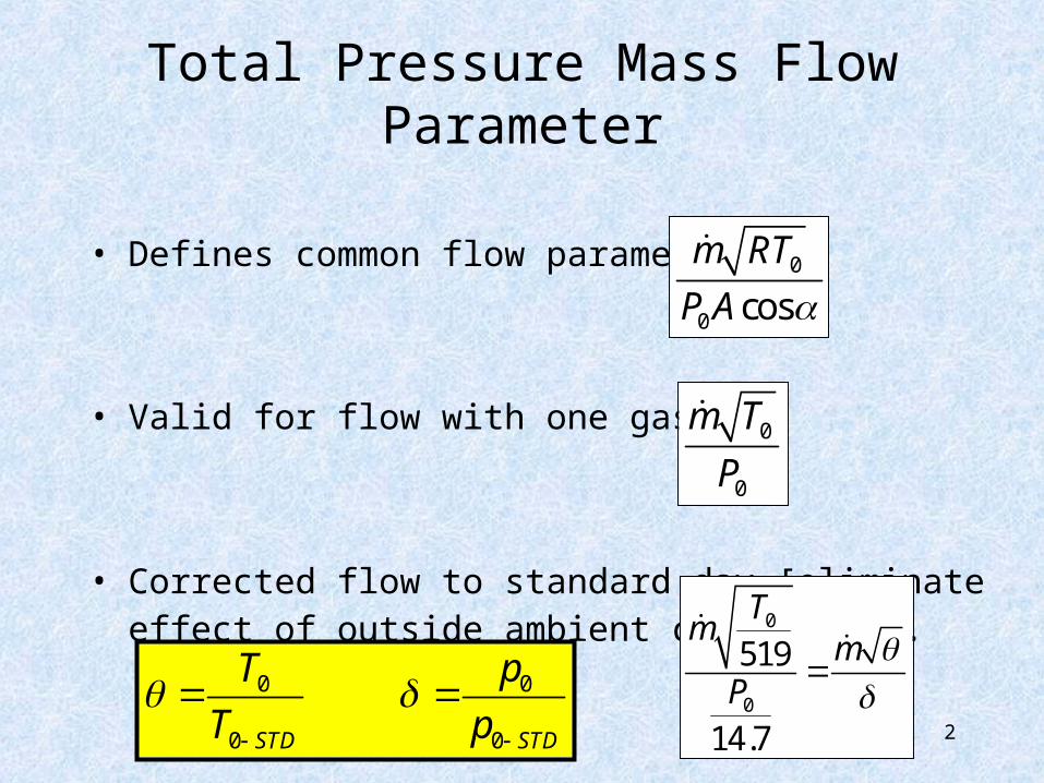
Total Pressure Mass Flow Parameter
• Defines common flow parameters.
• Valid for flow with one gas.
• Corrected flow to standard day [eliminate effect of outside ambient conditions].
0
0 cos
m RT
P A
0
0
m T
P
0
0
519
14.7
Tm
mP
0 0
0 0STD STD
T p
T p
3
Total Pressure Mass Flow Parameter
Std.
Std.
Ambient Temperature
Am
bie
nt P
ress
ure
B
A
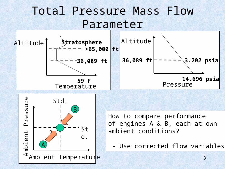
Stratosphere >65,000 ft
59 FTemperature
Altitude
3.202 psia
14.696 psiaPressure
36,089 ft
Altitude
36,089 ft
How to compare performanceof engines A & B, each at ownambient conditions?
- Use corrected flow variables
4
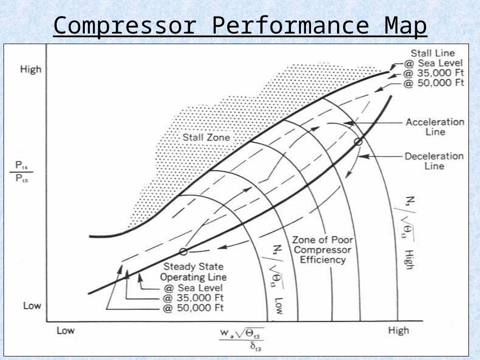
Compressor Performance Map

5
Turbomachine Map
• Functional behavior of map [mc, Nc, PR] is solely dependent on machine
• Behavior is applicable to – Compressors: axial, centrifugal– Turbines: axial, centrifugal– Multi-stage machines
• Choke limit: cannot pass more massflow– Sonic flow occurs at minimum area location
• Surge limit: onset of instability• Stall: too low mass flow, flow separates
6
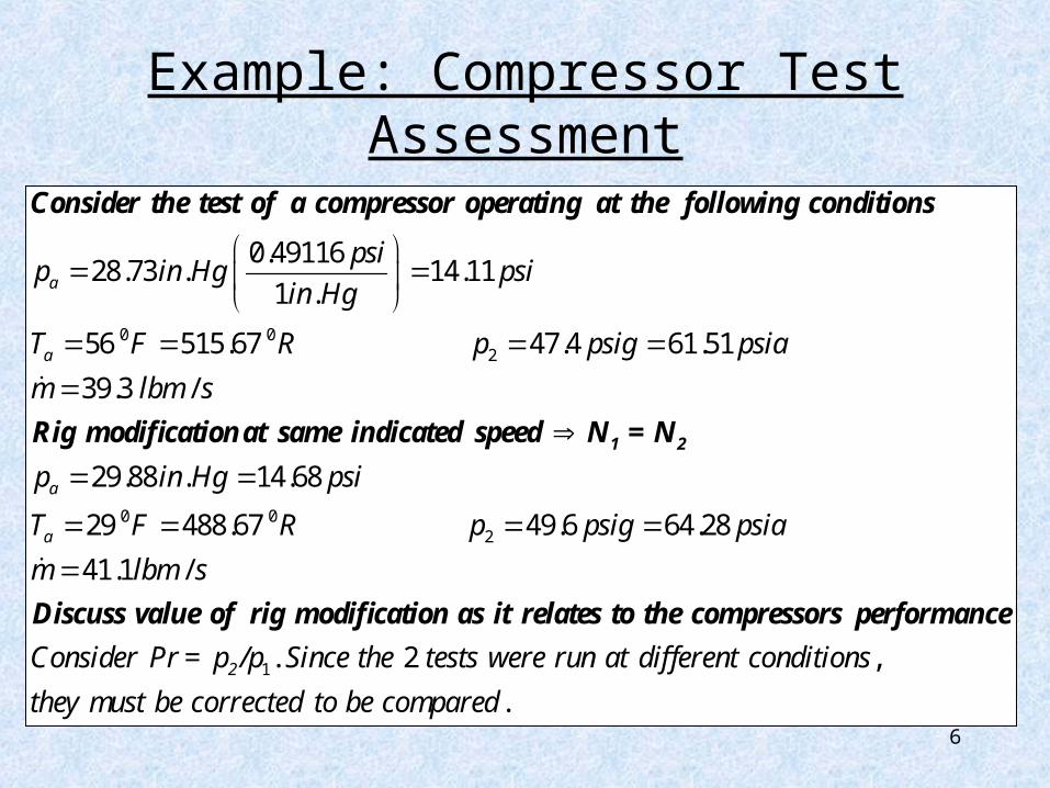
Example: Compressor Test Assessment
0 02
0.4911628.73 . 14.11
1 .
56 515.67 47.4 61.51
39.3 /
29
a
a
a
psip in Hg psi
in Hg
T F R p psig psia
m lbm s
p
1 2
Consider the test of a compressor operating at the following conditions
Rig modificationat same indicated speed N = N
0 02
1
.88 . 14.68
29 488.67 49.6 64.28
41.1 /
. 2 ,
a
2
in Hg psi
T F R p psig psia
m lbm s
Consider Pr = p /p Since the tests were run at different conditions
they mus
Discuss value of rig modification as it relates to the compressors performance
.t be corrected to be compared
7
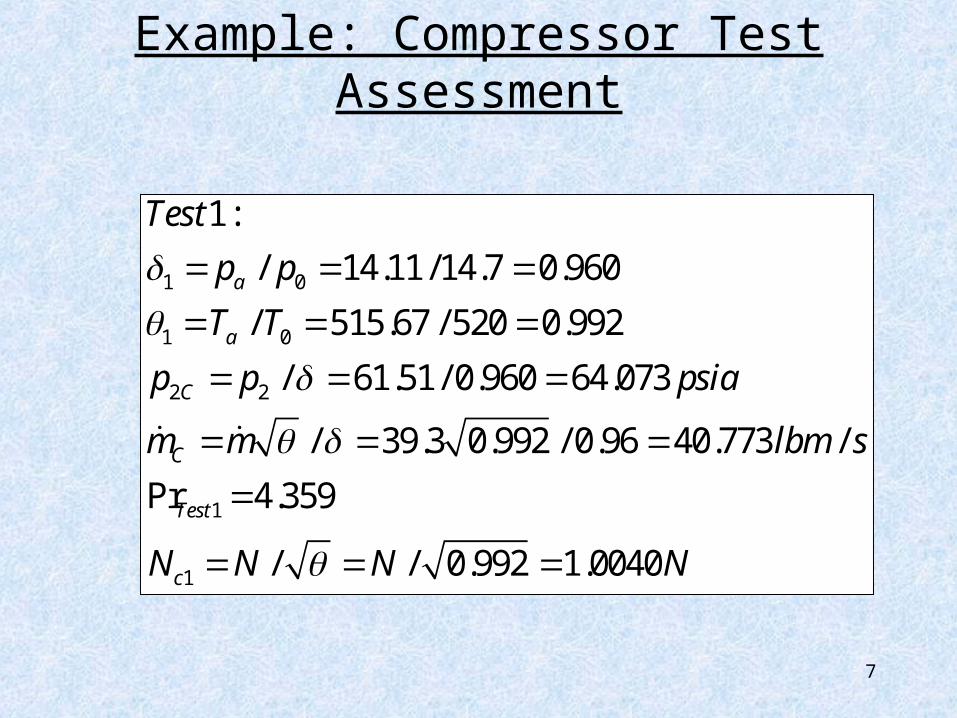
Example: Compressor Test Assessment
1 0
1 0
2 2
1
1
1:
/ 14.11 /14.7 0.960
/ 515.67 / 520 0.992
/ 61.51/ 0.960 64.073
/ 39.3 0.992 / 0.96 40.773 /
Pr 4.359
/ / 0.992 1.0040
a
a
C
C
Test
c
Test
p p
T T
p p psia
m m lbm s
N N N N
8
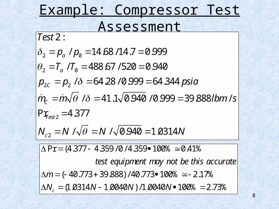
Example: Compressor Test Assessment
2 0
2 0
2 2
2
2
2 :
/ 14.68 /14.7 0.999
/ 488.67 / 520 0.940
/ 64.28 / 0.999 64.344
/ 41.1 0.940 / 0.999 39.888 /
Pr 4.377
/ / 0.940 1.0314
a
a
C
C
Test
c
Test
p p
T T
p p psia
m m lbm s
N N N N
Pr (4.377 4.359 / 0 / 4.359 100% 0.41%
( 40.773 39.888) / 40.773 100% 2.17%
(1.0314 1.0040 ) /1.0040 100% 2.73%c
test equipment may not be this accurate
m
N N N N
9
Example: Compressor Test Assessment
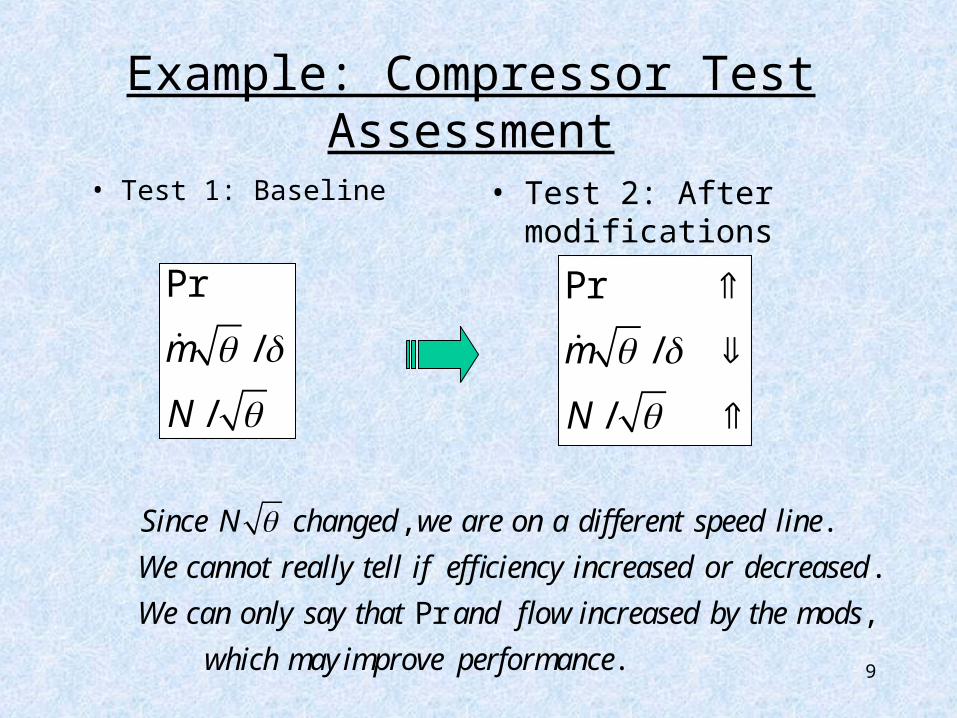
• Test 1: Baseline
• Test 2: After modifications
Pr
/
/
m
N
Pr
/
/
m
N
, .
.
Pr ,
.
Since N changed we are on a different speed line
We cannot really tell if efficiency increased or decreased
We can only say that and flow increased by the mods
which may improve performance
10
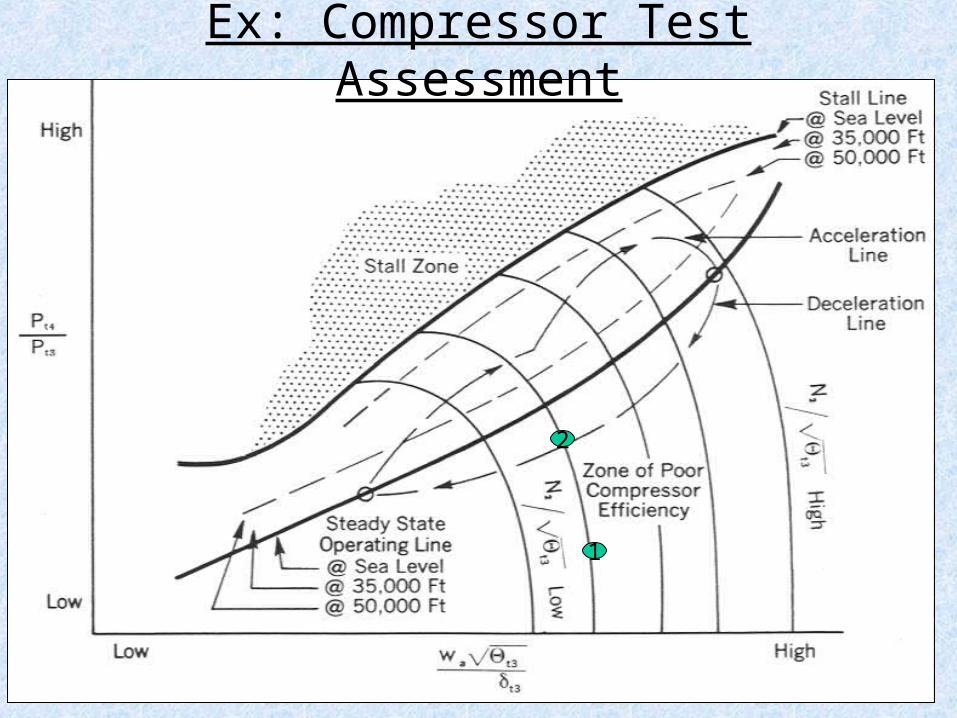
1
2
Ex: Compressor Test Assessment
11
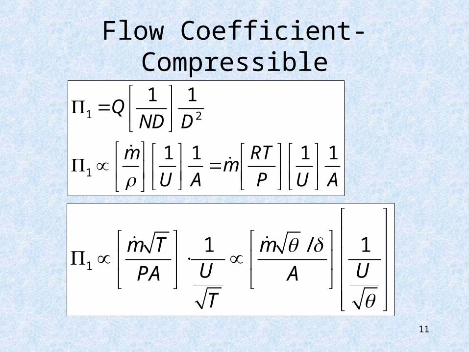
Flow Coefficient-Compressible
1 2
1
1 1
1 1 1 1
QND D
m RTm
U A P U A
1
1 / 1m T mU UPA AT
12
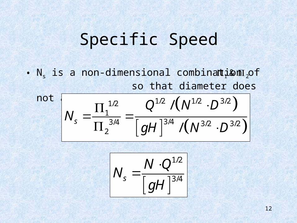
Specific Speed
• Ns is a non-dimensional combination of so that diameter does not appear.
1/2 1/2 3/21/21
3/43/4 3/2 3/22
/
/s
Q N DN
gH N D
1/2
3/4s
N QN
gH
21 &
13
Specific Speed
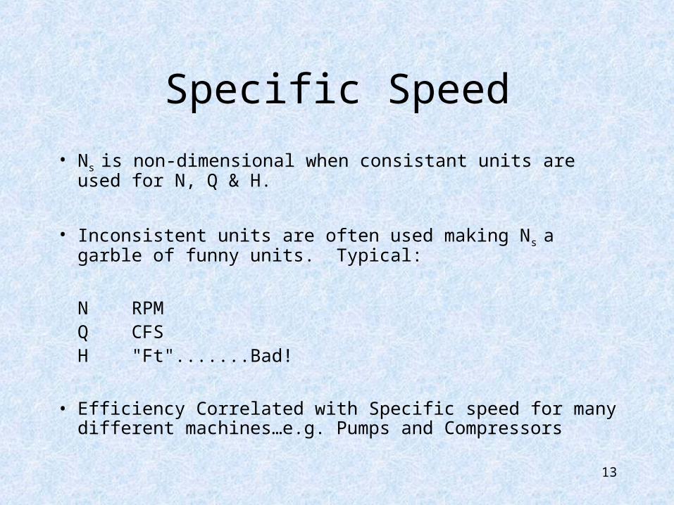
• Ns is non-dimensional when consistant units are used for N, Q & H.
• Inconsistent units are often used making Ns a garble of funny units. Typical:
N RPMQ CFSH "Ft".......Bad!
• Efficiency Correlated with Specific speed for many different machines…e.g. Pumps and Compressors
Specific Speed
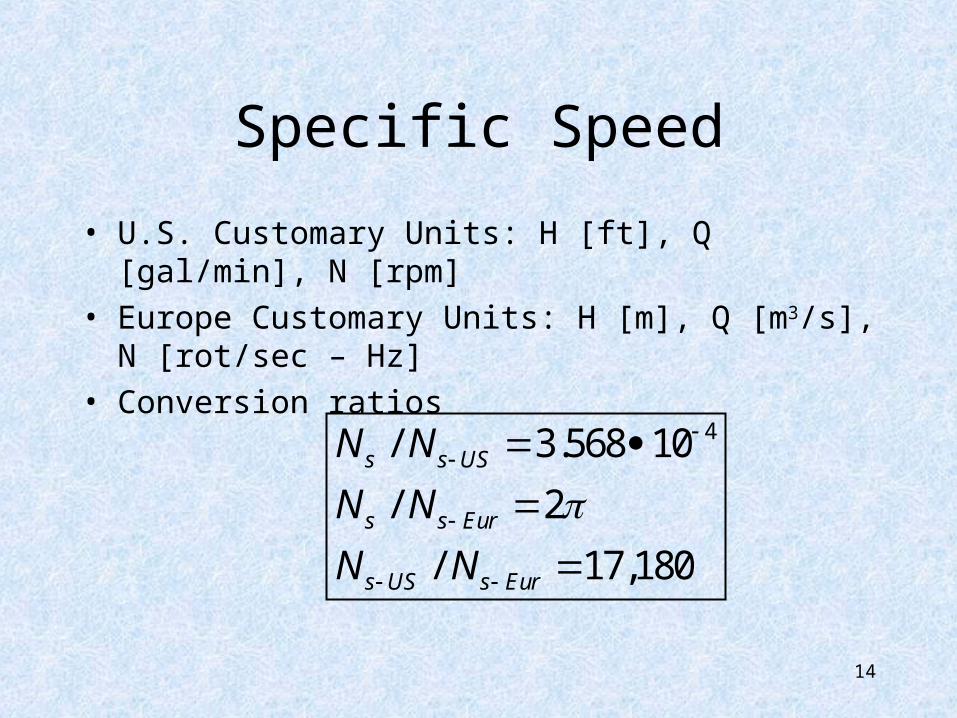
• U.S. Customary Units: H [ft], Q [gal/min], N [rpm]• Europe Customary Units: H [m], Q [m3/s], N [rot/sec –
Hz]• Conversion ratios
14
4/ 3.568 10
/ 2
/ 17,180
s s US
s s Eur
s US s Eur
N N
N N
N N
15
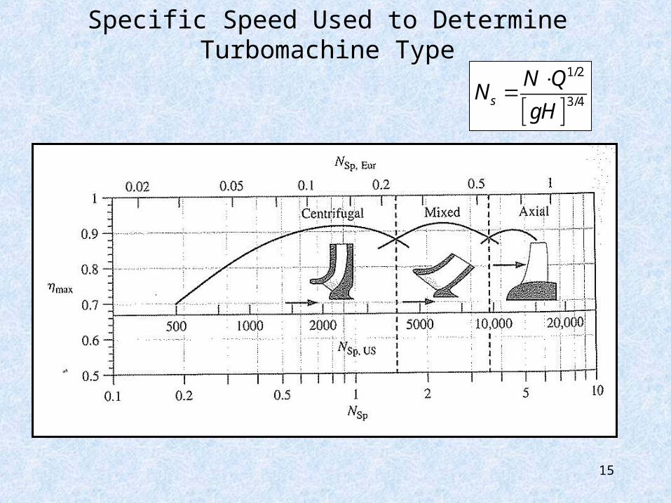
Specific Speed Used to Determine Turbomachine Type
1/2
3/4s
N QN
gH
16
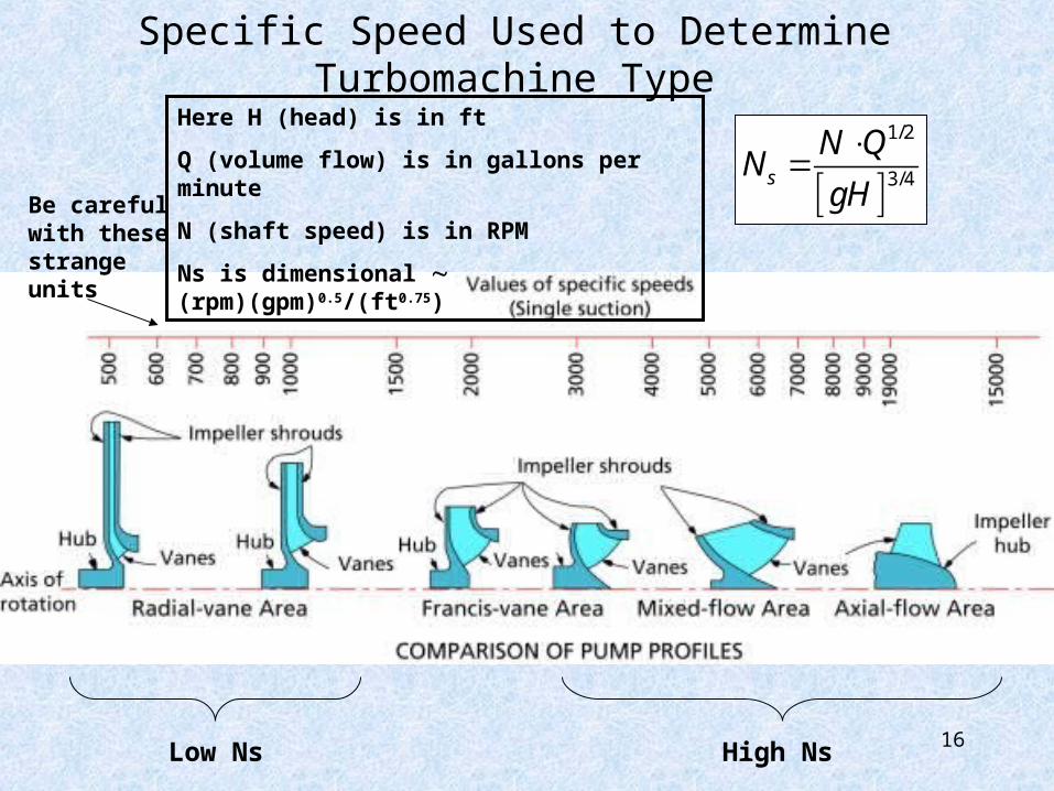
Specific Speed Used to Determine Turbomachine Type
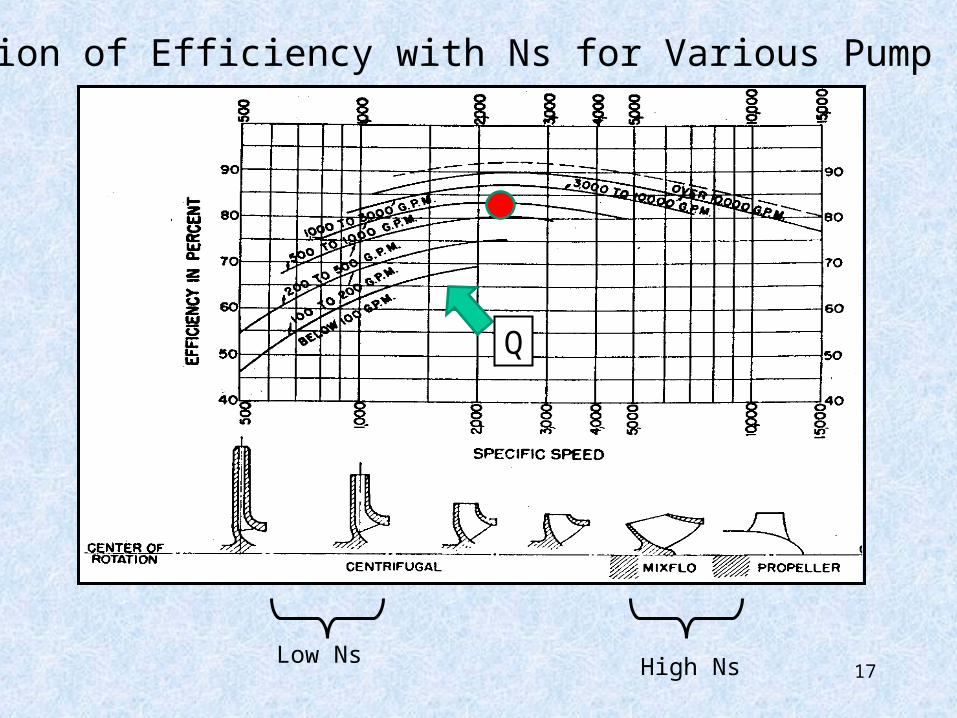
Low Ns High Ns
Be careful with these strange units
Here H (head) is in ft
Q (volume flow) is in gallons per minute
N (shaft speed) is in RPM
Ns is dimensional (rpm)(gpm)0.5/(ft0.75)
1/2
3/4s
N QN
gH
17
Variation of Efficiency with Ns for Various Pump Sizes
Low Ns High Ns
Q
18
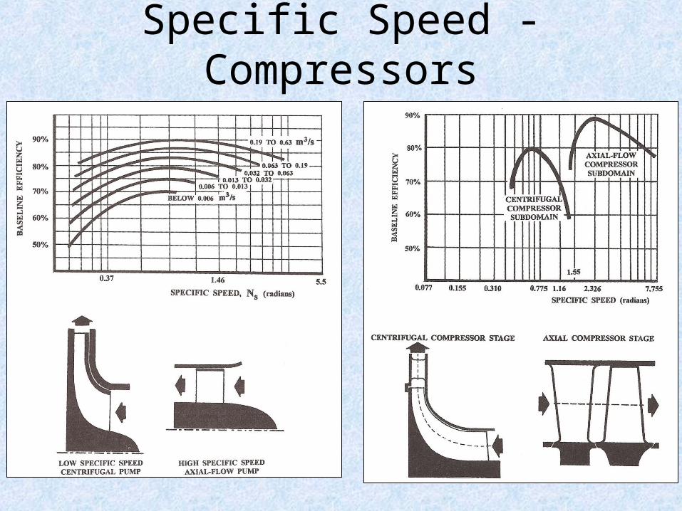
Specific Speed - Compressors
19
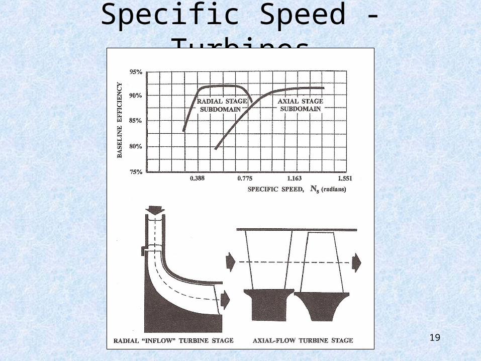
Specific Speed - Turbines
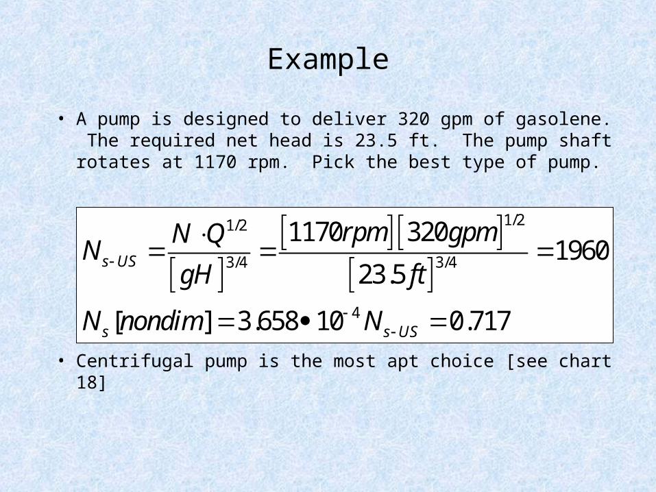
Example
• A pump is designed to deliver 320 gpm of gasolene. The required net head is 23.5 ft. The pump shaft rotates at 1170 rpm. Pick the best type of pump.
• Centrifugal pump is the most apt choice [see chart 18]
1/21/2
3/4 3/4
4
1170 3201960
23.5
[ ] 3.658 10 0.717
s US
s s US
rpm gpmN QN
gH ft
N nondim N
21
Specific Speed• Consider Range of Impellers
• If We Set:Inducer (Inlet) DiametersInducer (Inlet) Axial Velocity, FlowWork CoefficientBacksweep (Impeller Exit Angle)RPMPressure Rise, Inlet P & T
• Then:– Exit Velocity Diagram, Angles & Speeds are Set
22
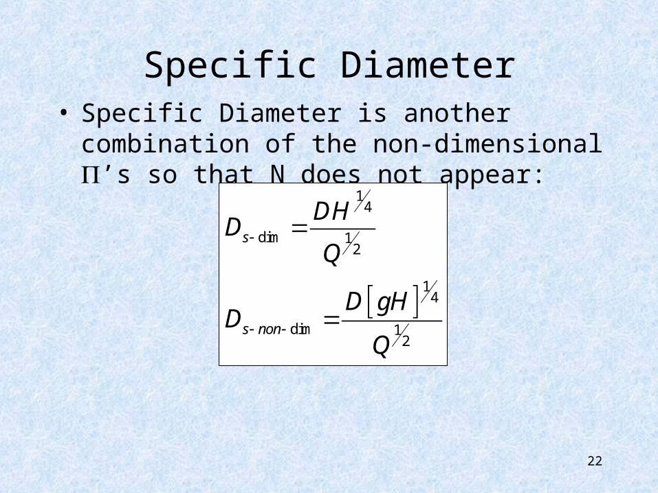
Specific Diameter• Specific Diameter is another combination of the
non-dimensional ’s so that N does not appear:
14
dim 12
14
dim 12
s
s non
DHD
Q
D gHD
Q
23
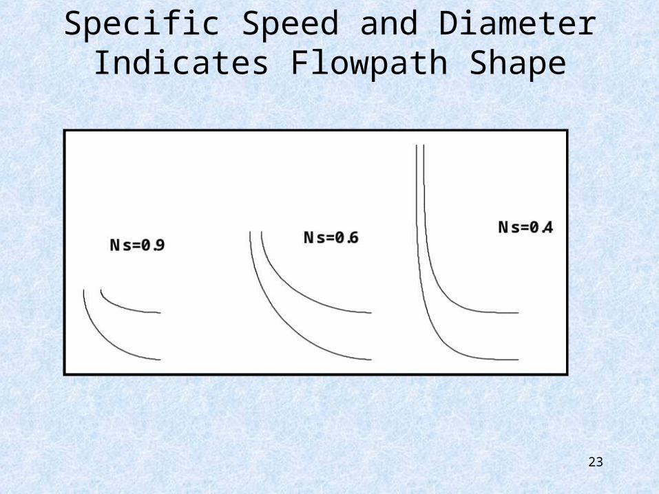
Specific Speed and Diameter Indicates Flowpath Shape
24
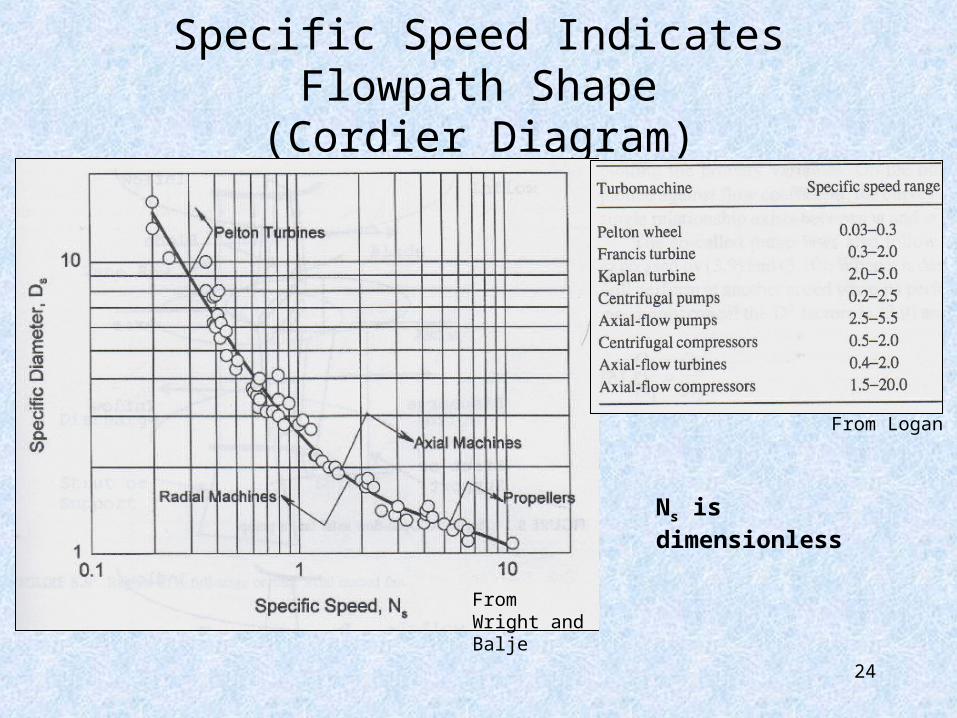
Specific Speed Indicates Flowpath Shape(Cordier Diagram)
From Wright and Balje
From Logan
Ns is dimensionless
25
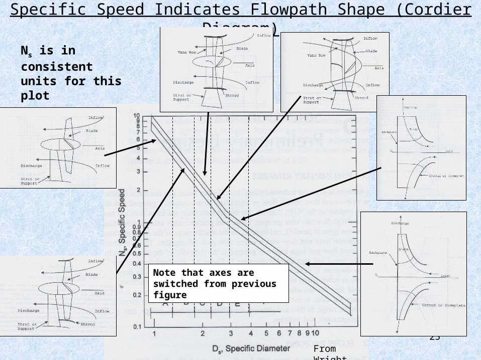
Specific Speed Indicates Flowpath Shape (Cordier Diagram)
Note that axes are switched from previous figure
From Wright
Ns is in consistent units for this plot
26
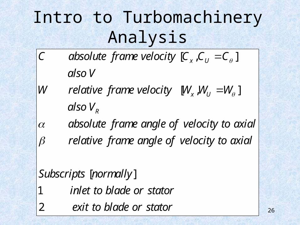
Intro to Turbomachinery Analysis
[ , ]
[ , ]
[ ]
1
2
x U
x U
R
C absolute frame velocity C C C
also V
W relative frame velocity W W W
also V
absolute frame angle of velocity to axial
relative frame angle of velocity to axial
Subscripts normally
inlet to blade or stator
exit to blade
or stator
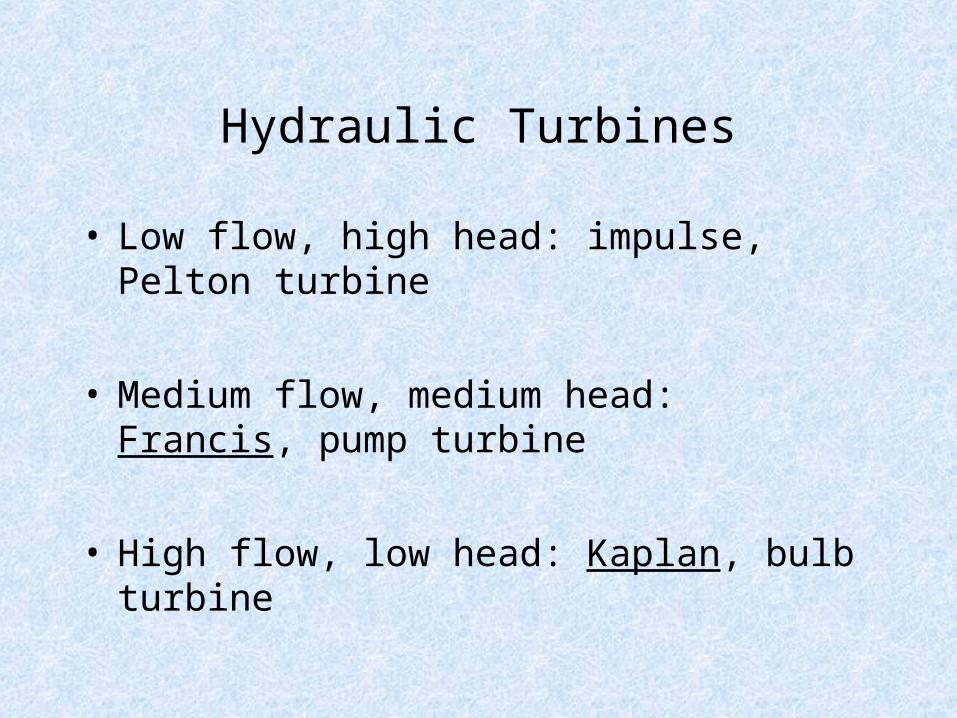
Hydraulic Turbines
• Low flow, high head: impulse, Pelton turbine
• Medium flow, medium head: Francis, pump turbine
• High flow, low head: Kaplan, bulb turbine
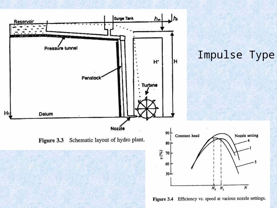
Impulse Type
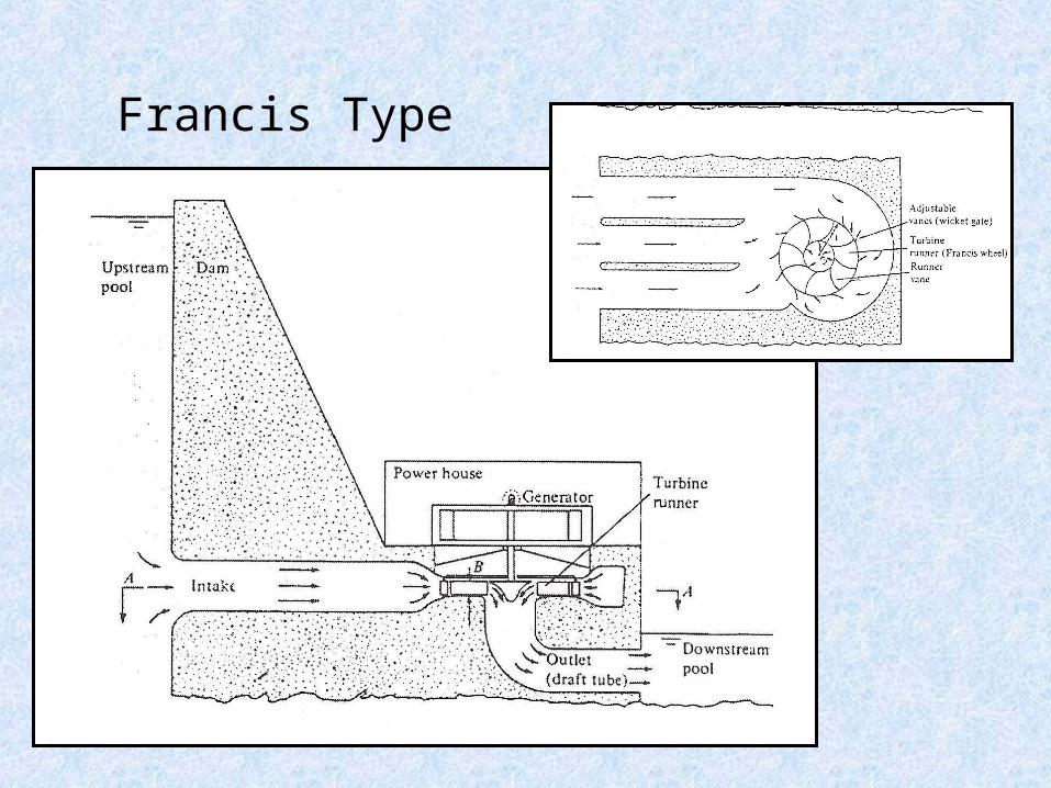
Francis Type
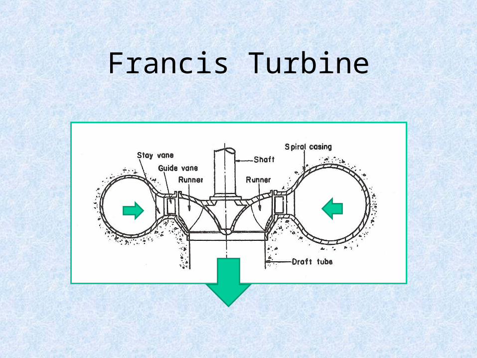
Francis Turbine
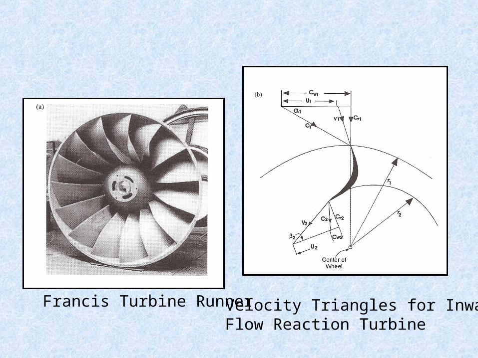
Francis Turbine Runner Velocity Triangles for InwardFlow Reaction Turbine
33
0.5 0.75 0.5 0.75
: 250 [ ]
18 [ ] 1500 [ ]
. . .
/ 1500 250 /18 2714
[16,17]s
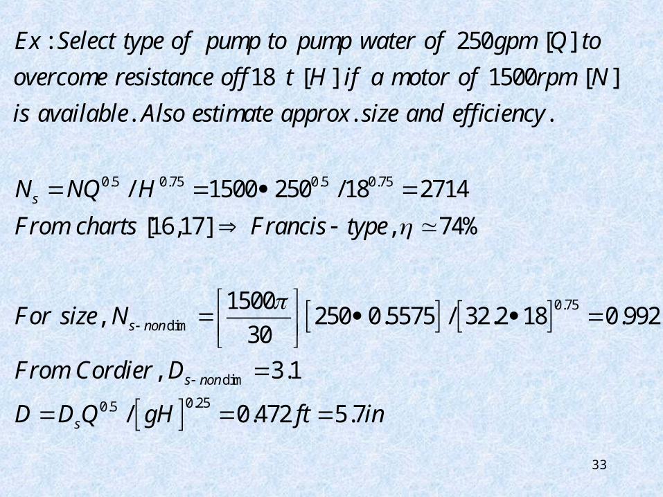
Ex Select type of pump to pump water of gpm Q to
overcome resistance of ft H if a motor of rpm N
is available Also estimate approx size and efficiency
N NQ H
From charts Franc
0.75
dim
dim
0.250.5
, 74%
1500, 250 0.5575 / 32.2 18 0.992
30
, 3.1
/ 0.472 5.7
s non
s non
s
is type
For size N
From Cordier D
D D Q gH ft in
34
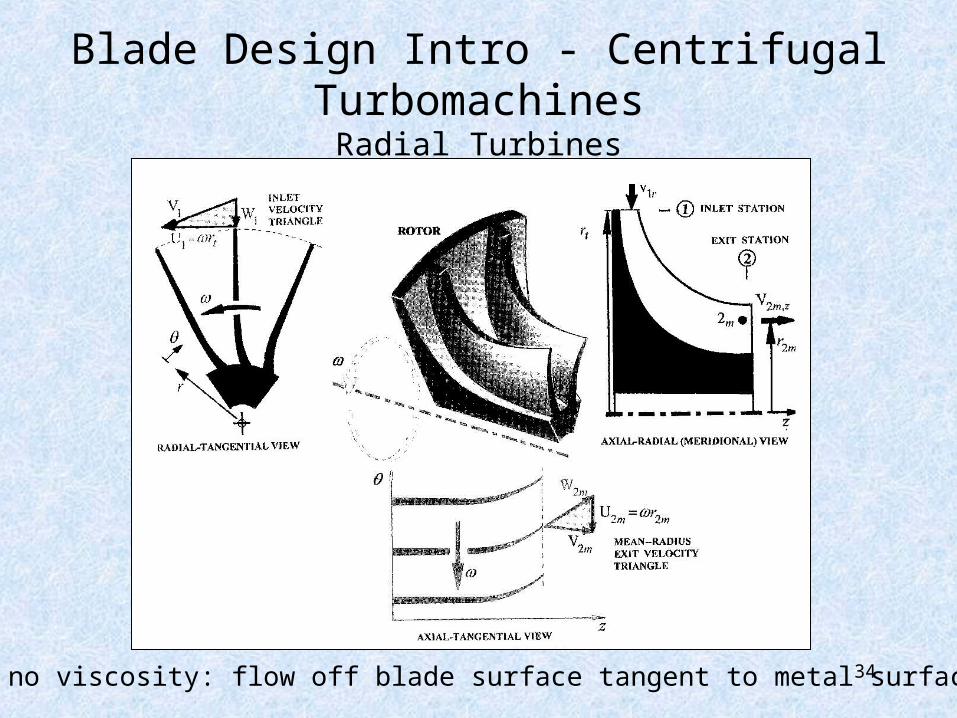
Blade Design Intro - Centrifugal TurbomachinesRadial Turbines
If no viscosity: flow off blade surface tangent to metal surface
35
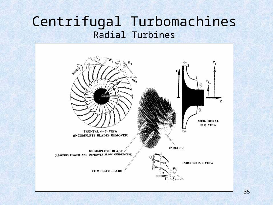
Centrifugal TurbomachinesRadial Turbines
36
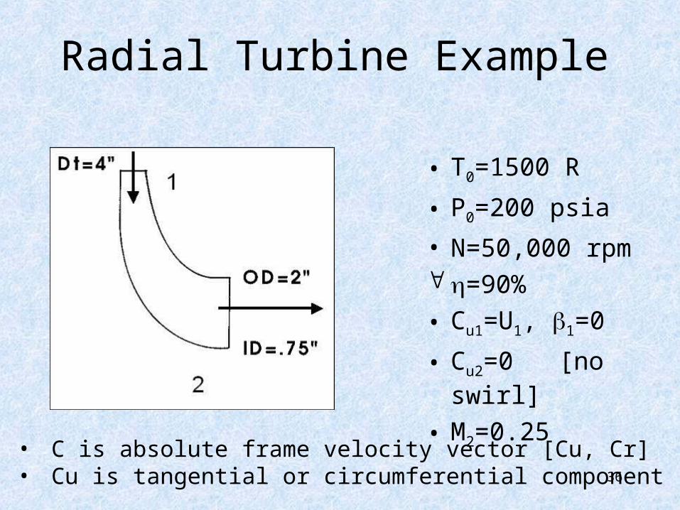
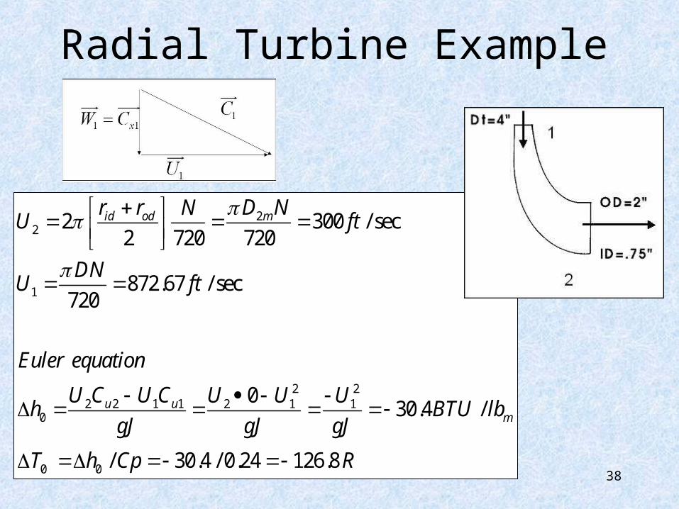
Radial Turbine Example
• T0=1500 R
• P0=200 psia
• N=50,000 rpm =90%
• Cu1=U1, 1=0
• Cu2=0 [no swirl]
• M2=0.25• C is absolute frame velocity vector [Cu, Cr]• Cu is tangential or circumferential component

37
Radial Turbine Example
• Tip Speed
• Entrance Velocity Diagram [W is relative frame velocity vector]
( )2 872.7
60 2 12 720
N D in NDU fps
1C��������������
1U��������������
1 1xW C����������������������������
38
Radial Turbine Example
22
1
2 22 2 1 1 2 1 1
0
0 0
2 300 / sec2 720 720
872.67 / sec720
030.4 /
/ 30.4 / 0.24 126.8
id od m
u um
r r D NNU ft
DNU ft
Euler equation
U C U C U U Uh BTU lb
gJ gJ gJ
T h Cp R
39
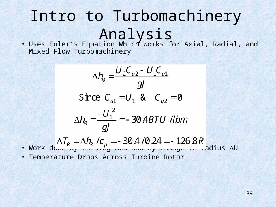
Intro to Turbomachinery Analysis• Uses Euler’s Equation Which Works for Axial, Radial, and Mixed
Flow Turbomachinery
• Work done by turning Cu and by change in radius U• Temperature Drops Across Turbine Rotor
2 2 1 10
1 1 2
21
0
0 0
Since & 0
30.4 /
/ 30.4 / 0.24 126.8
u u
u u
p
U C U Ch
gJ
C U C
Uh BTU lbm
gJ
T h c R
40
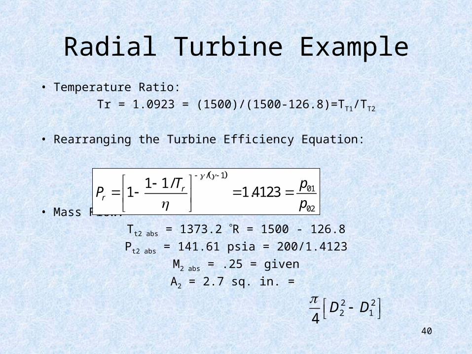
Radial Turbine Example• Temperature Ratio:
Tr = 1.0923 = (1500)/(1500-126.8)=TT1/TT2
• Rearranging the Turbine Efficiency Equation:
• Mass Flow:
Tt2 abs = 1373.2 R = 1500 - 126.8
Pt2 abs = 141.61 psia = 200/1.4123
M2 abs = .25 = given
A2 = 2.7 sq. in. =
/ 1
01
02
1 1/1 1.4123r
r
pTP
p
2 22 14
D D
41
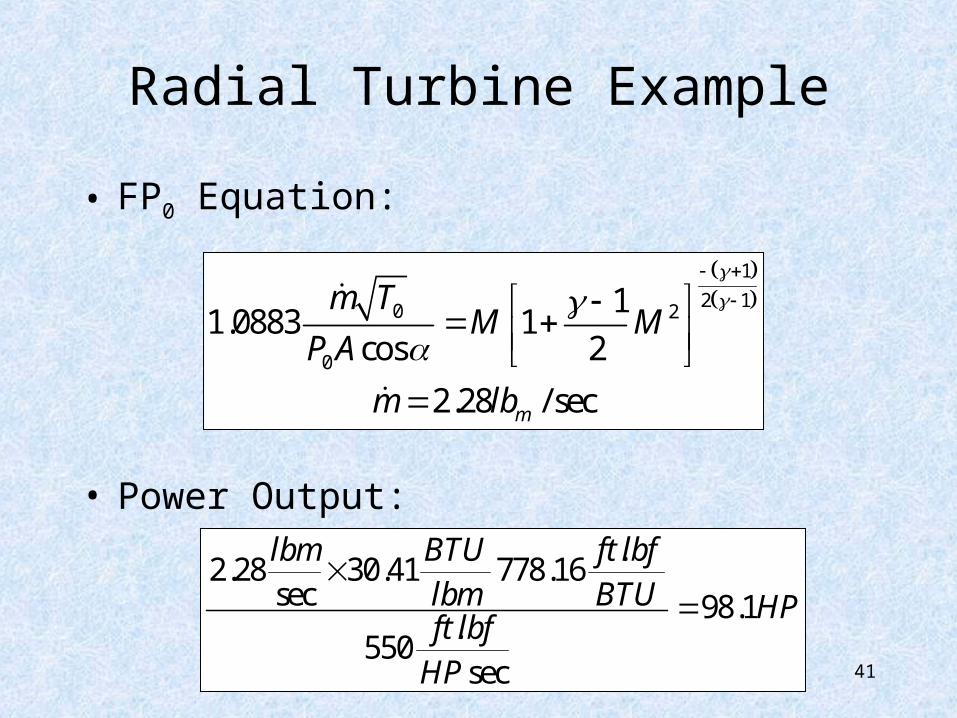
Radial Turbine Example
• FP0 Equation:
• Power Output:
1
2 10 2
0
11.0883 1
cos 2
2.28 / secm
m TM M
P A
m lb
.2.28 30.41 778.16
sec 98.1.
550sec
lbm BTU ft lbflbm BTU HPft lbfHP
42
Radial Turbine Example
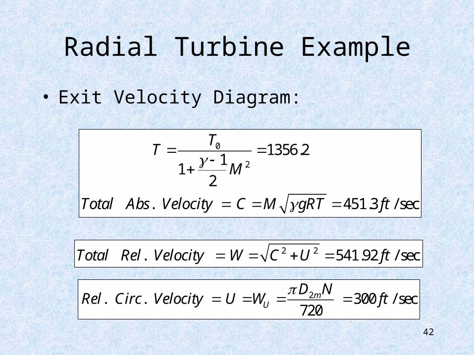
• Exit Velocity Diagram:
0
2
1356.21
12
. 451.3 / sec
TT
M
Total Abs Velocity C M gRT ft
2 2. 541.92 / secTotal Rel Velocity W C U ft
2. . 300 / sec720
mU
D NRel Circ Velocity U W ft
43
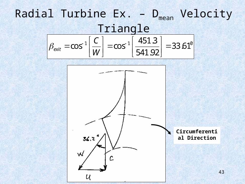
Radial Turbine Ex. – Dmean Velocity Triangle
Circumferential Direction
1 1 0451.3cos cos 33.61
541.92exit
C
W