Embed Size (px)
Citation preview
1
Transport Methods in Access Networks
and other subsidiary information
Access Networks
lectures
2008 / 09
2
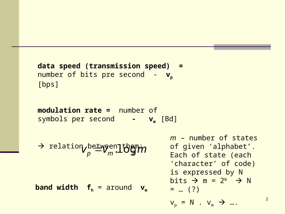
data speed (transmission speed) = number of bits pre second - vp [bps]
modulation rate = number of symbols per second - vm [Bd]
relation between them:
mvv mp 2log.
band width fh = around vm
m – number of states of given ‘alphabet’. Each of state (each ‘character’ of code) is expressed by N bits m = 2N N = … (?)
vp = N . vm ….
….. but: because of ingress and other disturbing the m must be less then 2N - there must be some distance (space, gap) to ensure good resolution (of states)
there must be choosen such method of transmission –
- which allows as narrow frequency band as possible
- which ensures at least minimal SNR
4
Classification of Methods for Digital Signal Transport
in the baseband : link codes (AMI, HDB3, 2BQ1, …) and PAM
in the modulation band (passband) : modulated signals (PSK, QAM, CAP, DMT)
Utilisation of available bandwidth – by means:
multistate encoding or modulation
numbers of parallel transport paths (so called inverse multiplexing), more carriers
scrambling generation of pseudonoise sequence equalization (or unification) of density of power spectrum
Duplex transport – types... – we have it classified more long time before
5
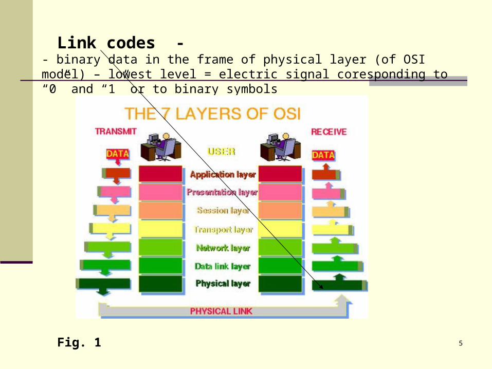
Link codes - - binary data in the frame of physical layer (of OSI model) – lowest level = electric signal coresponding to “0” and “1” or to binary symbols
Fig. 1
6
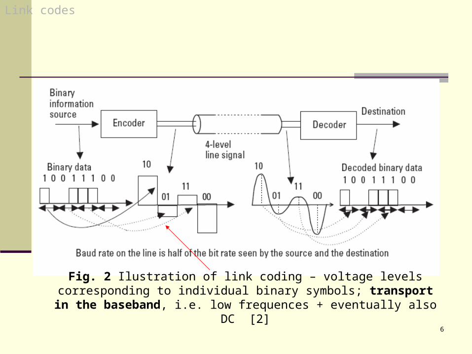
Fig. 2 Ilustration of link coding – voltage levels corresponding to individual binary symbols; transport in the baseband, i.e. low frequences +
eventually also DC [2]
Link codes
7
Link codes
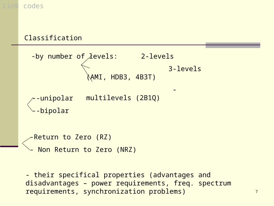
Classification
-by number of levels: 2-levels
3-levels (AMI, HDB3, 4B3T)
- multilevels (2B1Q)--unipolar
--bipolar
-Return to Zero (RZ)
- Non Return to Zero (NRZ)
- their specifical properties (advantages and disadvantages – power requirements, freq. spectrum requirements, synchronization problems)
8
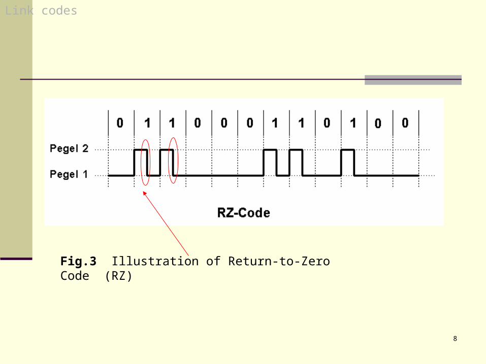
Fig.3 Illustration of Return-to-Zero Code (RZ)
Link codes
9
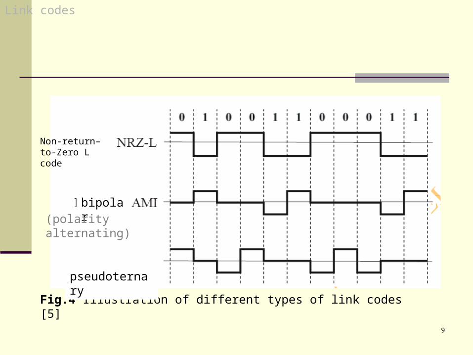
Fig.4 Illustration of different types of link codes [5]
Non-return–to-Zero L code
bipolar
pseudoternary
Link codes
(polarity alternating)
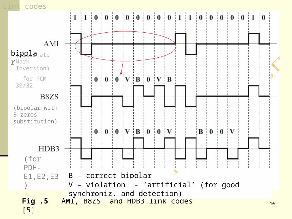
10Fig .5 AMI, B8ZS and HDB3 link codes [5]
bipolar
B – correct bipolar signalV – violation - ‘artificial’ (for good synchroniz. and detection)
Link codes
(Alternate Mark Inversion)
- for PCM 30/32
(for PDH-E1,E2,E3)
(bipolar with 8 zeros substitution)
11
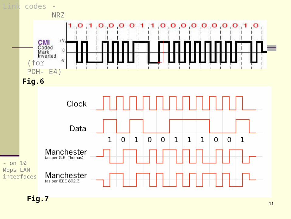
Fig.6
Fig.7
Link codes - NRZ
(for PDH- E4)
- on 10 Mbps LAN interfaces
12
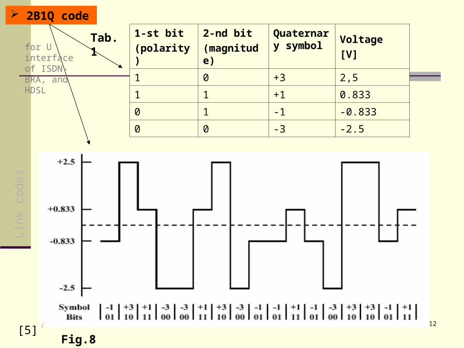
Tab.1
[5]Fig.8
1-st bit
(polarity)
2-nd bit
(magnitude)
Quaternary symbol
Voltage
[V]
1 0 +3 2,5
1 1 +1 0.833
0 1 -1 -0.833
0 0 -3 -2.5
2B1Q codeLi
nk c
odes
for U interface of ISDN-BRA, and HDSL
13
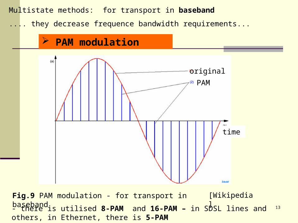
PAM modulation
original
PAM
time
[Wikipedia]Fig.9 PAM modulation - for transport in baseband
Multistate methods: for transport in baseband
.... they decrease frequence bandwidth requirements...
- there is utilised 8-PAM and 16-PAM – in SDSL lines and others, in Ethernet, there is 5-PAM
14
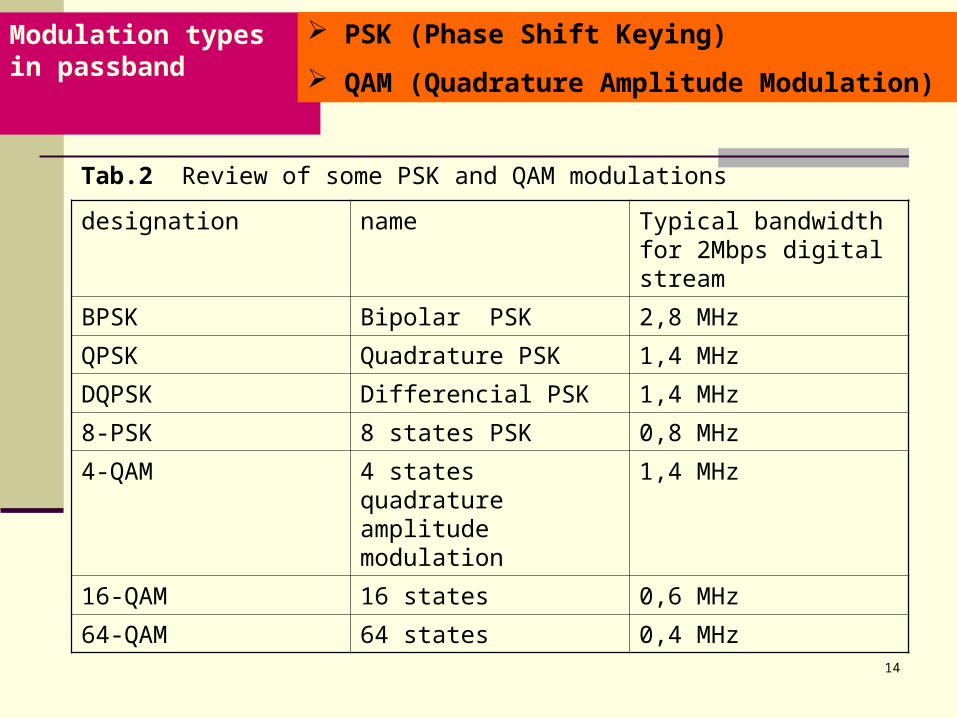
Modulation types in passband
Tab.2 Review of some PSK and QAM modulations
designation name Typical bandwidth for 2Mbps digital stream
BPSK Bipolar PSK 2,8 MHz
QPSK Quadrature PSK 1,4 MHz
DQPSK Differencial PSK 1,4 MHz
8-PSK 8 states PSK 0,8 MHz
4-QAM 4 states quadrature amplitude modulation
1,4 MHz
16-QAM 16 states 0,6 MHz
64-QAM 64 states 0,4 MHz
PSK (Phase Shift Keying)
QAM (Quadrature Amplitude Modulation)
15
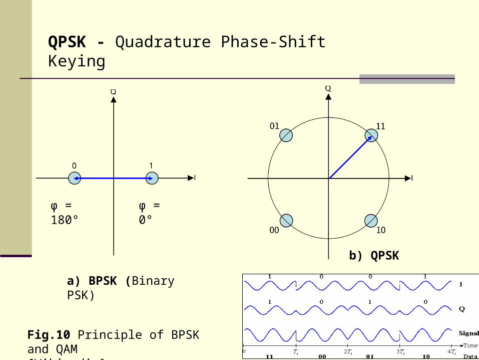
QPSK - Quadrature Phase-Shift Keying
Fig.10 Principle of BPSK and QAM [Wikipedia]
a) BPSK (Binary PSK)
b) QPSK
φ = 0°φ = 180°
16
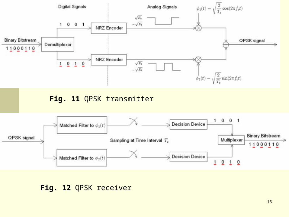
Fig. 11 QPSK transmitter
Fig. 12 QPSK receiver
17
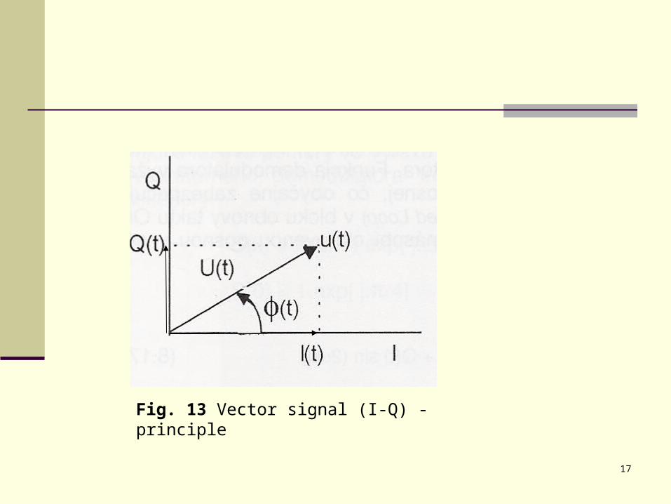
Fig. 13 Vector signal (I-Q) - principle
18
QAM
- a modulation scheme which conveys data by changing (modulating) the amplitude of two carrier waves. These two waves, usually sinusoids, are out of phase with each other by 90° and are thus called quadrature carriers—hence the name of the scheme.
19
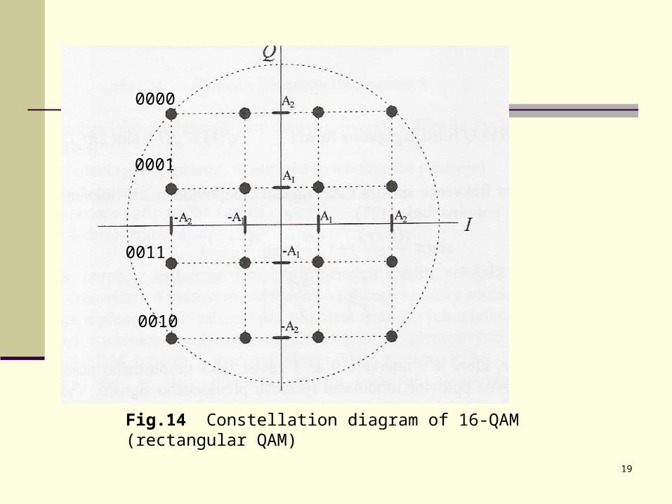
Fig.14 Constellation diagram of 16-QAM (rectangular QAM)
0000
0001
0010
0011
20
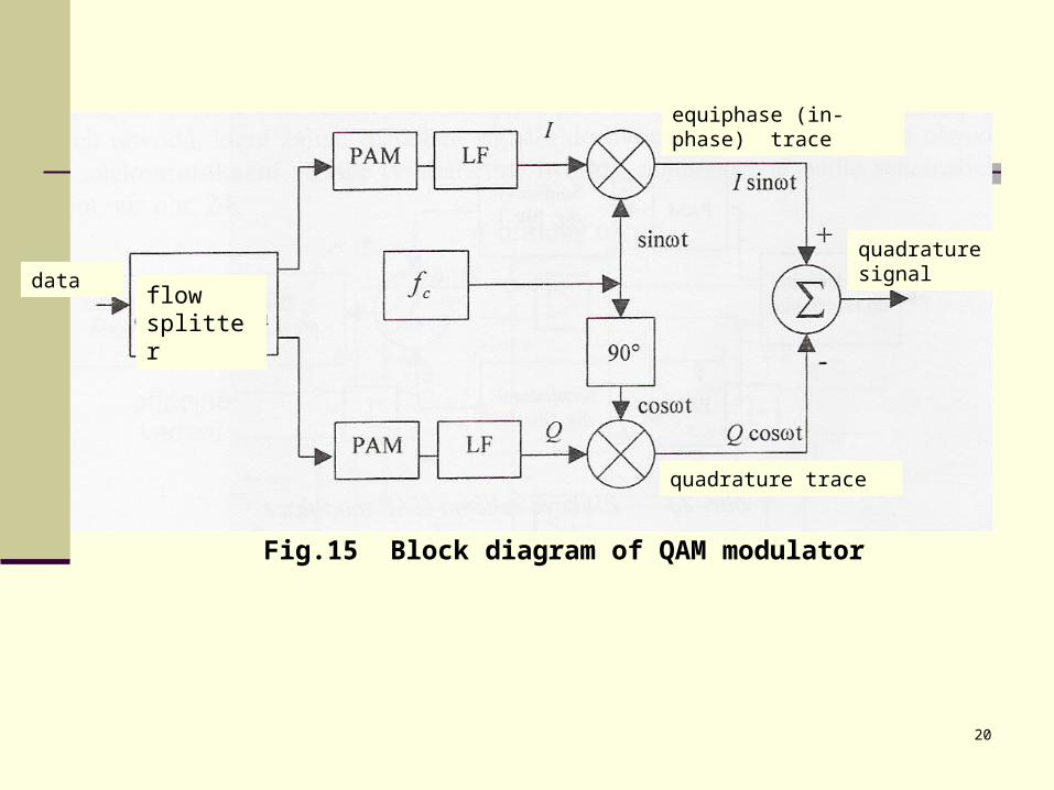
Fig.15 Block diagram of QAM modulator
equiphase (in-phase) trace
quadrature trace
quadrature signal
flow splitter
data
21[1]
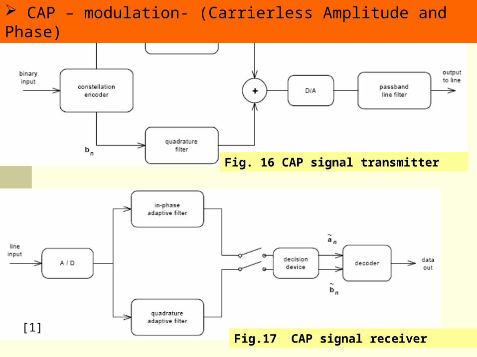
CAP – modulation- (Carrierless Amplitude and Phase)
Instead of modulating the amplitude of two carrier waves, CAP generates QAM signal by combining two PAM signals filtered through two filters designed so that their impulse responses form a Hilbert pair.
22
Fig. 16 CAP signal transmitter
Fig.17 CAP signal receiver[1]
CAP – modulation- (Carrierless Amplitude and Phase)
23
[1]
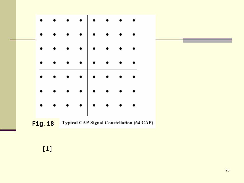
Fig.18
24
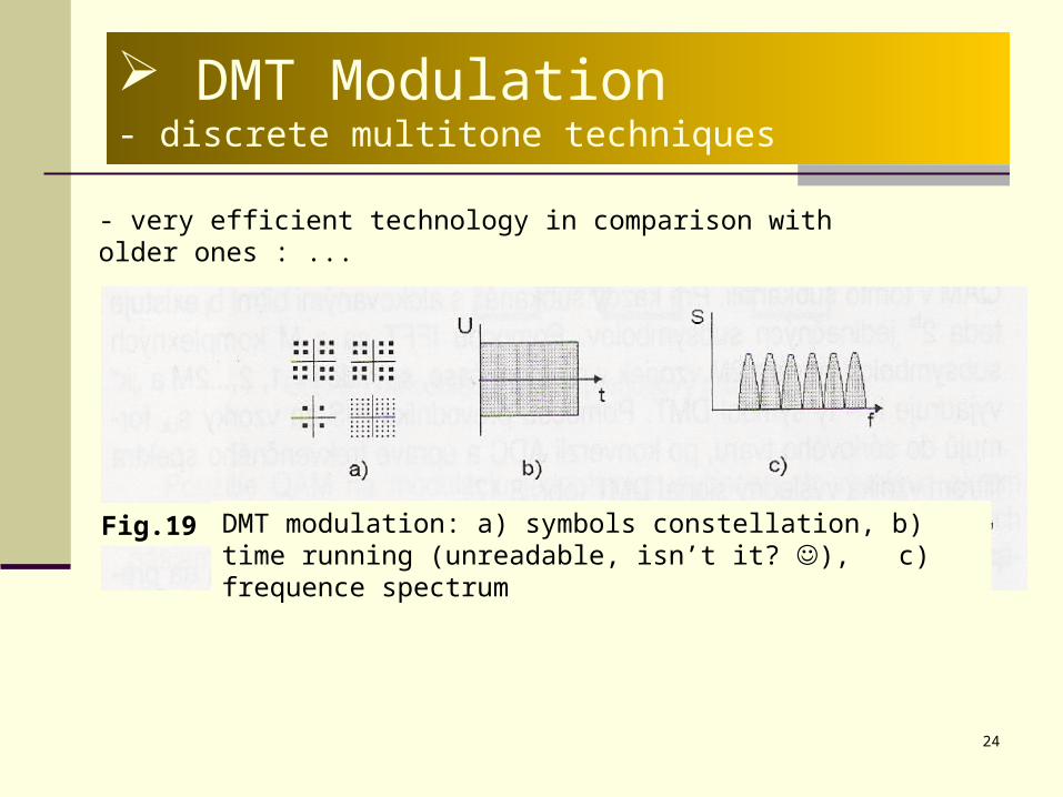
DMT Modulation- discrete multitone techniques
- very efficient technology in comparison with older ones : ...
Fig.19 DMT modulation: a) symbols constellation, b) time running (unreadable, isn’t it? ), c) frequence spectrum
25
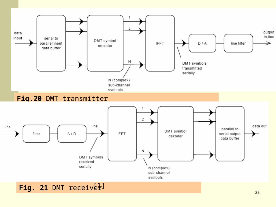
Fig.20 DMT transmitter
Fig. 21 DMT receiver [1]
26
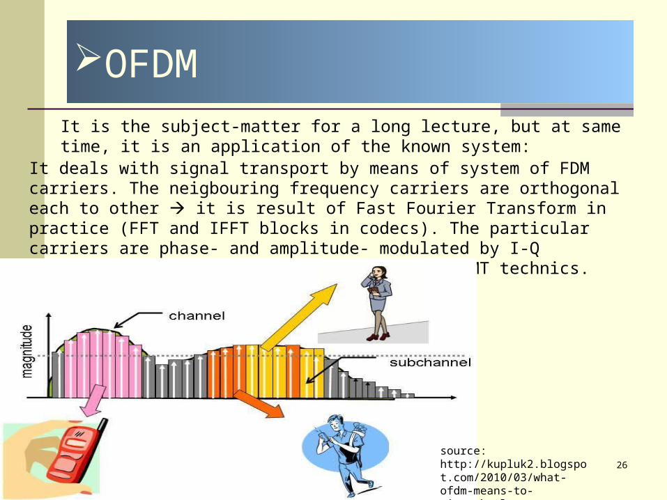
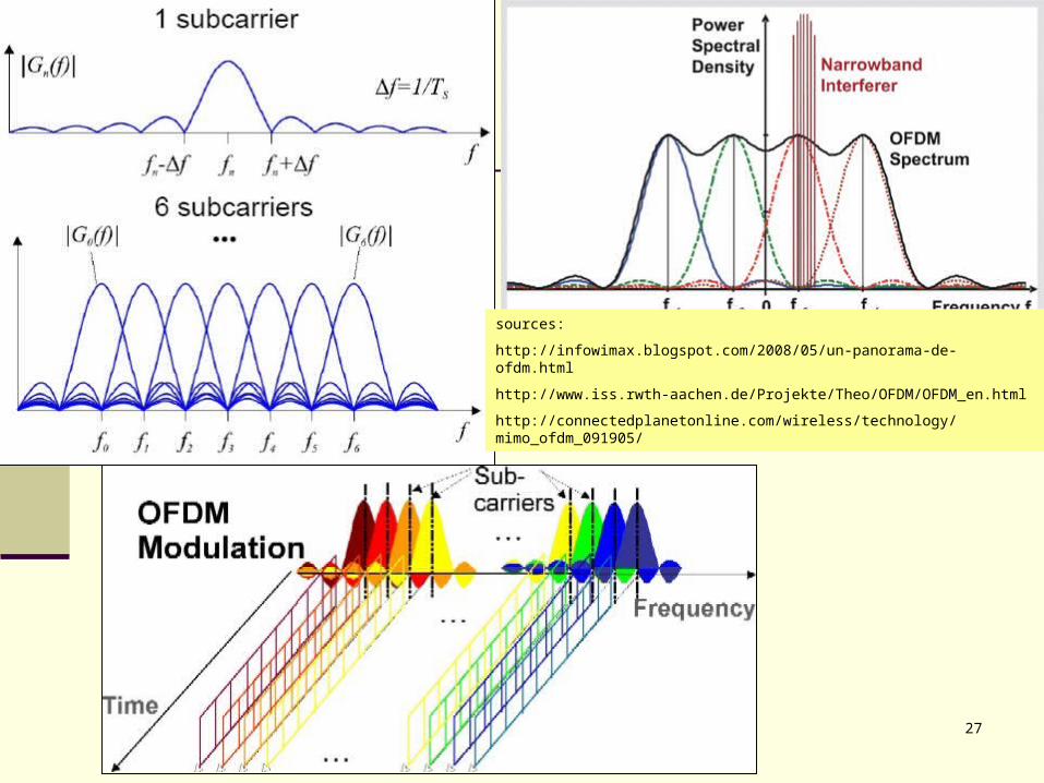
OFDM
It deals with signal transport by means of system of FDM carriers. The neigbouring frequency carriers are orthogonal each to other it is result of Fast Fourier Transform in practice (FFT and IFFT blocks in codecs). The particular carriers are phase- and amplitude- modulated by I-Q modulation, i.e. QAM. That is the basis of DMT technics.
source: http://kupluk2.blogspot.com/2010/03/what-ofdm-means-to-wimax.html
It is the subject-matter for a long lecture, but at same time, it is an application of the known system:
27
sources:
http://infowimax.blogspot.com/2008/05/un-panorama-de-ofdm.html
http://www.iss.rwth-aachen.de/Projekte/Theo/OFDM/OFDM_en.html
http://connectedplanetonline.com/wireless/technology/mimo_ofdm_091905/
28
-In telecommunication, trellis modulation (also known as trellis coded modulation, or simply TCM) is a modulation scheme which allows highly efficient transmission of information over band-limited channels such as telephone lines. Trellis modulation was invented by Gottfried Ungerboeck in 1982.
-...
[Wikipedia]
Trellis modulation
29
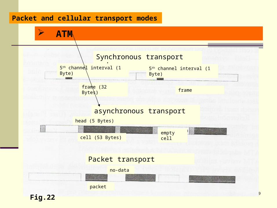
Packet and cellular transport modes
Fig.22
ATM
Synchronous transport mode
asynchronous transport mode
Packet transport
5th channel interval (1 Byte) 5th channel interval (1 Byte)
frame (32 Bytes)frame
head (5 Bytes)
cell (53 Bytes)empty cell
packet
no-data
30
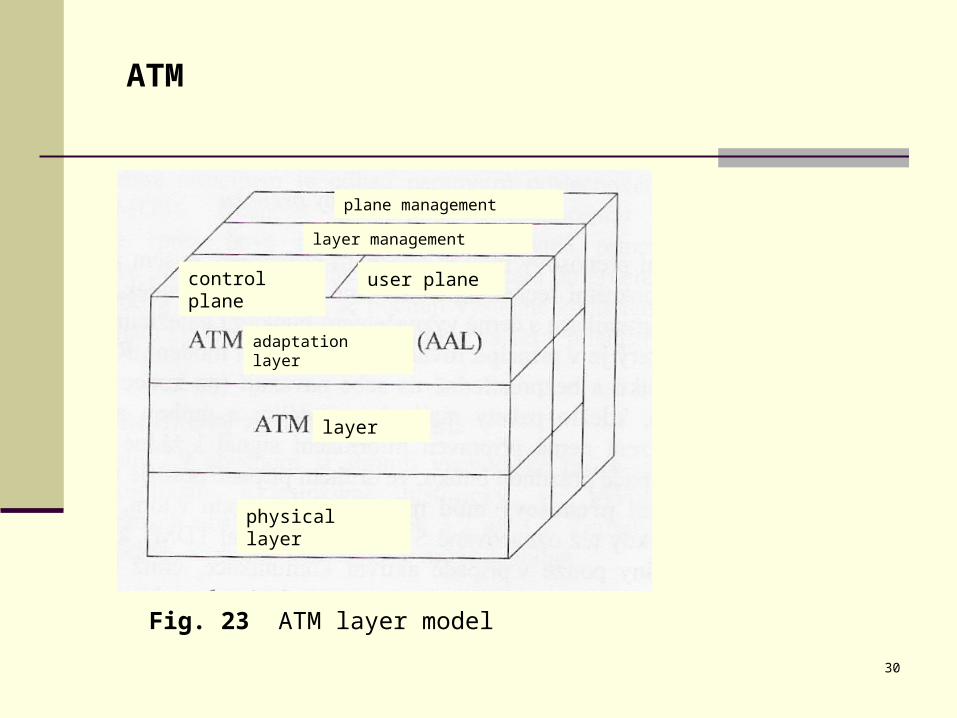
ATM
Fig. 23 ATM layer model
plane management
layer management
adaptation layer
layer
physical layer
control plane user plane
31
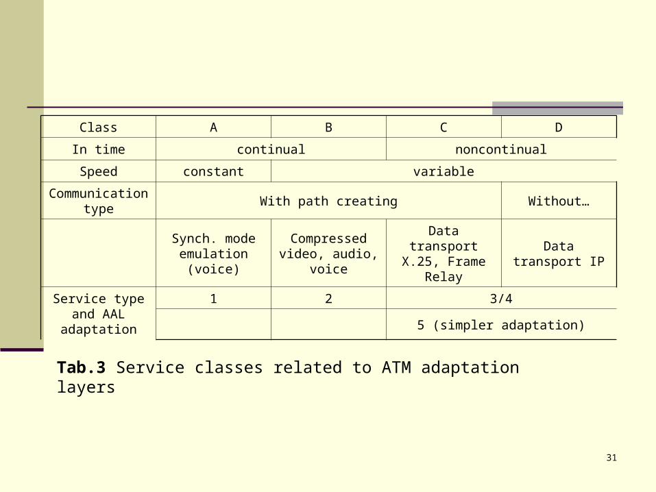
Tab.3 Service classes related to ATM adaptation layers
Class A B C D
In time continual noncontinual
Speed constant variable
Communication type
With path creating Without…
Synch. mode emulation (voice)
Compressed video, audio,
voice
Data transport X.25, Frame
RelayData transport IP
Service type and AAL adaptation
1 2 3/4
5 (simpler adaptation)
32
Another appendices
33
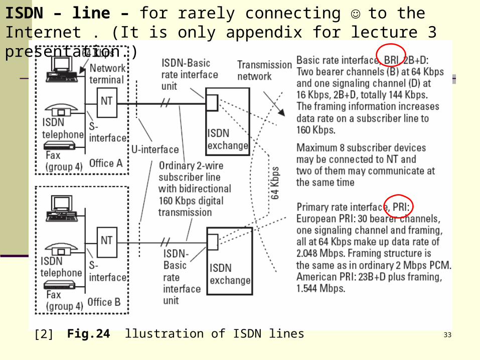
ISDN – line – for rarely connecting to the Internet . (It is only appendix for lecture 3 presentation.)
[2] Fig.24 llustration of ISDN lines
34
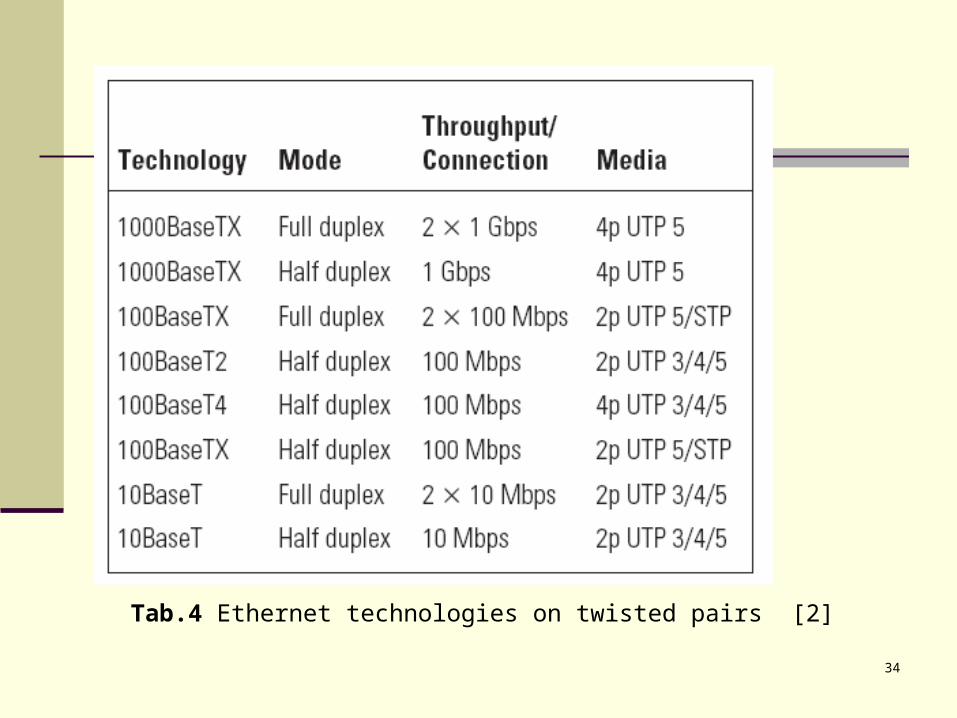
Tab.4 Ethernet technologies on twisted pairs [2]
35
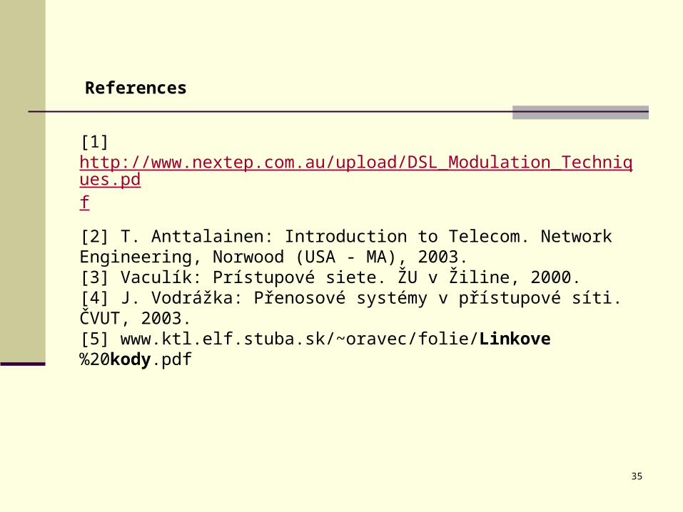
References
[1] http://www.nextep.com.au/upload/DSL_Modulation_Techniques.pdf
[2] T. Anttalainen: Introduction to Telecom. Network Engineering, Norwood (USA - MA), 2003.[3] Vaculík: Prístupové siete. ŽU v Žiline, 2000.[4] J. Vodrážka: Přenosové systémy v přístupové síti. ČVUT, 2003.[5] www.ktl.elf.stuba.sk/~oravec/folie/Linkove%20kody.pdf