Embed Size (px)
Citation preview

1 Temperature Derating Guide
1.1.1 Abstract
This paper provides detailed data regarding the operation of the VLT HVAC Drive FC102 at varyingambient temperature and load. There is given application specific guidelines, and the influenceon the switching frequency is documented.
1.1.2 Introduction
This paper provides detailed information regarding the operation of the VLT HVAC Drive FC102 atdifferent ambient temperature and load conditions. Application specific guidelines are given andthe influence of the switching frequency is detailed.
VLT HVAC Drive FC102 General SpecificationsThe VLT HVAC Drive FC102 has a specified continuous output current to be able to supply a widerange of motors with different efficiencies. Full continuous rated output current can be suppliedin ambient temperatures up to 45°C. With a typical full load current of EFF2 motors (see MotorEfficiency), full output shaft power can be maintained with the VLT HVAC Drive FC102 operatingin ambient temperatures up to 50°C.
Frequency Converter Selection and DeratingThe sizing of the frequency converter is generally dependant on a number of factors including:
• Motor efficiency and full load current
• Ambient temperature
• Mains supply voltage
• Motor cable length and type (e.g. screened or unscreened)
• Number of options installed (impacts the internal temperature within the frequency con-verter)
• Switching frequency and/or switching pattern (impacts the heat generation within thefrequency converter)
Motor EfficiencyEFF classification of motors is predominantly relevant in European Union countries although it isalso adopted or being considered to be adopted in other countries. It is applicable to specific motortypes (e.g. totally enclosed fan ventilated, three phase AC squirrel cage induction motors in therange 1.1 to 90kW, having 2 or 4 poles, rated for 400V, 50Hz, S1 duty class).
Other motor efficiency classifications or Minimum Efficiency Performance Standards (MEPS) existelsewhere in the world. For example in North America NEMA MG1 defines motor efficiency levelsfor “energy efficient” and “premium efficiency” motors for a wider range of motors than thoseunder the EFF classification (e.g. 1 to 500HP, 2, 4 and 6 pole) and in Australia and New ZealandAS/NZS 1359.5-2004, applicable to three phase, 2, 4, 6 and 8 pole motors from 0.73kW to<185kW, defines minimum efficiency levels approximately equivalent to those of the EuropeanEFF1 level and high efficiency motors as having an even higher efficiency. Some of these efficiencyrequirements are voluntary and others are legally enforceable.
The efficiency of a motor is one factor that affects the full load current rating of a motor andtherefore has an impact on the ambient temperature rating of the frequency converter for usewith that motor when operating at full load. For example the frequency converter may be rated
VLT® HVAC Drive FC 102 Application Note 1 Temperature Derating Guide
MN.11.A1.02 - VLT® is a registered Danfoss trademark 1
1
for operation in an ambient temperature of say 50 °C when operating at full load current of a15kW EFF2 motor but it may be rated for operation in say 54 °C when operating at full load currentof a 15kW high efficient motor according to AS/NZS 1359.5-2004 or rated for operation in say 52°C when operating at full load current of a 20HP premium efficiency motor according to NEMAMG1.
Ambient TemperatureIf the maximum ambient temperature in which the frequency converter will be installed is equalto or below the limit defined for full continuous FC output current in the Specifications section ofthe Operating Instructions or the General Specifications and Troubleshooting section of the DesignGuide and if the factory default switching frequency will be used, there is no need to considerderating of the output current.
However if the maximum ambient temperature is higher than that defined, this guide should beused to ensure the derated continuous output current of the frequency converter at this highermaximum ambient temperature is higher than the full load current of the motor or at least higherthan the maximum running current of the motor for the application.
Mains supply voltageThe mains supply voltage has a minimal affect for low powers and therefore the ambient tem-perature rating, current rating and derating curves are shown for the worst case situation (i.e.highest mains voltage). For higher powers (enclosure size D and above), different derating curvesdependant on the mains supply voltage are shown.
Motor cable length and typeThe motor cable length and type has an affect because due to the high switching frequency ofthe frequency converter it not only has to supply the full load current of the motor but also“charging” currents in the motor cable. The longer the motor cable or if the cable is screenedinstead of unscreened, the higher these charging currents. The motor cable length and type hasmore affect at low powers and much less at higher powers. For all powers the ambient temper-ature, current rating and derating curves are given for the worst case situation (150m screened/300m unscreened motor cable).
Number of options installedThe frequency converter can have up to three options installed (Option A (BMS high level interfacecommunication options), Option B (I/O extension options) and Option C (application options)).The number of options installed can affect the internal temperature of the frequency converter(depending on enclosure size). Therefore for some enclosure sizes different derating curves areshown depending on the number of options installed.
Switching frequency, switching pattern and automatic adaptationThe frequency converter can be programmed to use a different switching pattern (60 AVM orSFAVM (parameter 14-00)) or switching frequency (1kHz to 16kHz (depending on size) (parameter14-01)).
For most applications the default settings (60 AVM and 4kHz (depending on size)) will be adequatebecause the frequency converter automatically adapts these to ensure performance if necessary.
The frequency converter constantly checks for critical levels of internal temperature, load current,high voltage on the intermediate circuit and low motor speeds. As a response to a critical level,the frequency converter can adjust the switching frequency and/or change the switching patternin order to ensure the performance of the frequency converter. The capability to automaticallyreduce the output current (i.e. automatically derate the output current) extends the acceptableoperating conditions even further. This automatic adaptation function ensures continued operationof the fan, pump or compressor even in extreme operating conditions. It also helps to minimize
1 Temperature Derating Guide VLT® HVAC Drive FC 102 Application Note
2 MN.11.A1.02 - VLT® is a registered Danfoss trademark
1
the acoustic noise from the motor resulting from the frequency converter when operating at lowspeeds, which is the most critical area of operation for acoustic noise because at low speeds theacoustic noise from the motor and fan themselves is low.
The graphs that follow provide information about the mutual influence on load, ambient temper-ature, switching frequency, and switching pattern.
1.1.3 Motor Acoustic Noise Optimization
Additional acoustic noise from a motor when using a frequency converter can be a concern onsome applications. On pump or compressor applications it is typically not a concern but on fanapplications it may be. Typically it is a concern when the fan is operating at mid to low speeds.At high speeds any additional noise as a result of the frequency converter, is drowned out by thenoise from the motor and fan themselves but at mid to low speeds it may be noticeable.
Changing the switching frequency to a higher value can help to reduce acoustic noise from themotor and is the most common solution to this.
Changing the switching pattern from the default setting is not often done. However, the acousticnoise from a motor will typically be less when using SFAVM than 60 AVM for the same switchingfrequency, although the internal frequency converter losses will be higher. The automatic adap-tation function described above sets the switching pattern to SFAVM when operating at low outputfrequencies (approximately <30% nominal motor frequency) to help minimize acoustic motornoise. It also sets the switching pattern to 60 AVM when operating at high output frequencies(approximately >80% of nominal motor frequency) to help minimize internal losses when thefrequency converter load is at its highest (particularly applicable to fans, centrifugal pumps andcentrifugal chiller compressors.) To minimize acoustic motor noise in the operating range betweenapproximately 30% and 80% motor nominal frequency a combination of changing the switchingpattern and/or switching frequency can give the best results.
However, if the switching frequency is increased and depending on the application, if the switchingpattern is changed from default, this can result in increased full load losses in the frequency con-verter and therefore the continuous current rating of the frequency converter should be deratedin accordance with the graphs that follow.
VLT® HVAC Drive FC 102 Application Note 1 Temperature Derating Guide
MN.11.A1.02 - VLT® is a registered Danfoss trademark 3
1
1.1.4 Application Dependant Derating
Fans, centrifugal pumps and centrifugal chiller compressorsDue to the nature of these loads the maximum load (i.e. output current) occurs at nominal/max-imum output frequency. The automatic adaptation function described above, ensures that whenthe frequency converter is operating at its highest load and therefore when its internal losses aregreatest, it is operating with 60 AVM switching pattern irrespective of what the switching pattern(parameter 14-00) is programmed to. Therefore for these applications it is only necessary to referto the graphs that follow in illustration 1.1 - 1.9 even if the switching pattern parameter is changedfrom default to minimize motor audible noise at mid to low output frequencies.
Screw, scroll and reciprocating compressorsDue to the nature of these loads the maximum load (i.e. output current) could occur at all outputfrequencies (e.g. the torque and current required to operate a screw compressor at 60% speedwill typically be similar to that at 100% speed.) Therefore for these applications it is necessary torefer to either the graphs in illustration 1.1 - 1.9 (60 AVM) OR the graphs in illustration 1.10 - 1-18(SFAVM), depending on the switching pattern programmed (parameter 14-00.) Typically this pa-rameter will not be changed from default, so only the graphs in illustration 1.1 - 1.9 need be used,but additional graphs are shown in illustration 1.10 - 1-18 for SFAVM switching pattern for com-pleteness. (SFAVM results in higher internal losses than 60 AVM and therefore the derating factorsare different.)
1.1.5 How to Find the Derating Factor
1. Determine the application.
1a If it is a fan, centrifugal pump or centrifugal compressor use steps 2 to 4 todetermine which graph applies from illustration 1.1 - 1.9.
1b If it is a screw, scroll or reciprocating compressor and the switching pattern(parameter 14-00) is not changed from default (60 AVM), use steps 2 to 4 todetermine which graph applies from illustration 1.1 - 1.9.
1c If it is a screw, scroll or reciprocating compressor and the switching pattern(parameter 14-00) has been changed from default to SFAVM, use steps 2 to 4to determine which graph applies from illustration 1.10 - 1-18.
2. Find the enclosure type from the tables below, e.g. a 7.5 kW with mains supply 3 x 380– 480 V and IP 55 rating is enclosure type A5.
3. If the drive is enclosure type D or E then take note of the supply voltage for the drive.
4. Find the relevant derating curve based on the information found above: application andswitching pattern, enclosure type and supply voltage (if relevant).
1 Temperature Derating Guide VLT® HVAC Drive FC 102 Application Note
4 MN.11.A1.02 - VLT® is a registered Danfoss trademark
1
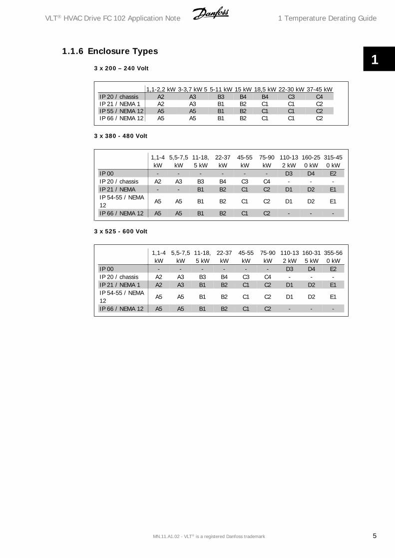
1.1.6 Enclosure Types
3 x 200 – 240 Volt
1,1-2,2 kW 3-3,7 kW 5 5-11 kW 15 kW 18,5 kW 22-30 kW 37-45 kWIP 20 / chassis A2 A3 B3 B4 B4 C3 C4IP 21 / NEMA 1 A2 A3 B1 B2 C1 C1 C2IP 55 / NEMA 12 A5 A5 B1 B2 C1 C1 C2IP 66 / NEMA 12 A5 A5 B1 B2 C1 C1 C2
3 x 380 - 480 Volt
1,1-4kW
5,5-7,5kW
11-18,5 kW
22-37kW
45-55kW
75-90kW
110-132 kW
160-250 kW
315-450 kW
IP 00 - - - - - - D3 D4 E2IP 20 / chassis A2 A3 B3 B4 C3 C4 - - -IP 21 / NEMA - - B1 B2 C1 C2 D1 D2 E1IP 54-55 / NEMA12
A5 A5 B1 B2 C1 C2 D1 D2 E1
IP 66 / NEMA 12 A5 A5 B1 B2 C1 C2 - - -
3 x 525 - 600 Volt
1,1-4kW
5,5-7,5kW
11-18,5 kW
22-37kW
45-55kW
75-90kW
110-132 kW
160-315 kW
355-560 kW
IP 00 - - - - - - D3 D4 E2IP 20 / chassis A2 A3 B3 B4 C3 C4 - - -IP 21 / NEMA 1 A2 A3 B1 B2 C1 C2 D1 D2 E1IP 54-55 / NEMA12
A5 A5 B1 B2 C1 C2 D1 D2 E1
IP 66 / NEMA 12 A5 A5 B1 B2 C1 C2 - - -
VLT® HVAC Drive FC 102 Application Note 1 Temperature Derating Guide
MN.11.A1.02 - VLT® is a registered Danfoss trademark 5
1
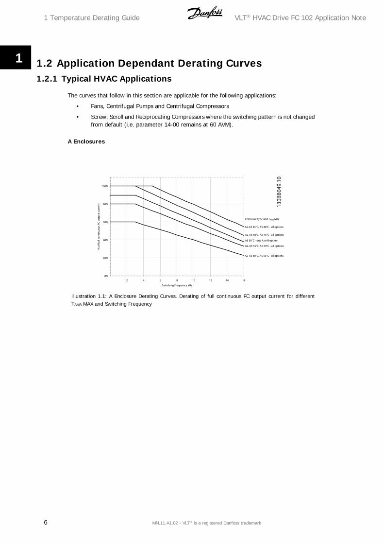
1.2 Application Dependant Derating Curves1.2.1 Typical HVAC Applications
The curves that follow in this section are applicable for the following applications:
• Fans, Centrifugal Pumps and Centrifugal Compressors
• Screw, Scroll and Reciprocating Compressors where the switching pattern is not changedfrom default (i.e. parameter 14-00 remains at 60 AVM).
A Enclosures
Illustration 1.1: A Enclosure Derating Curves. Derating of full continuous FC output current for differentTAMB MAX and Switching Frequency
1 Temperature Derating Guide VLT® HVAC Drive FC 102 Application Note
6 MN.11.A1.02 - VLT® is a registered Danfoss trademark
1
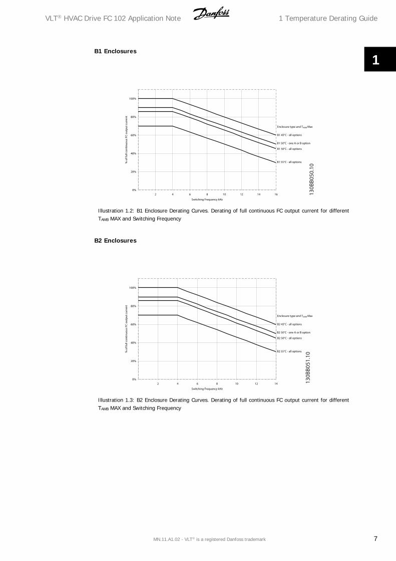
B1 Enclosures
Illustration 1.2: B1 Enclosure Derating Curves. Derating of full continuous FC output current for differentTAMB MAX and Switching Frequency
B2 Enclosures
Illustration 1.3: B2 Enclosure Derating Curves. Derating of full continuous FC output current for differentTAMB MAX and Switching Frequency
VLT® HVAC Drive FC 102 Application Note 1 Temperature Derating Guide
MN.11.A1.02 - VLT® is a registered Danfoss trademark 7
1
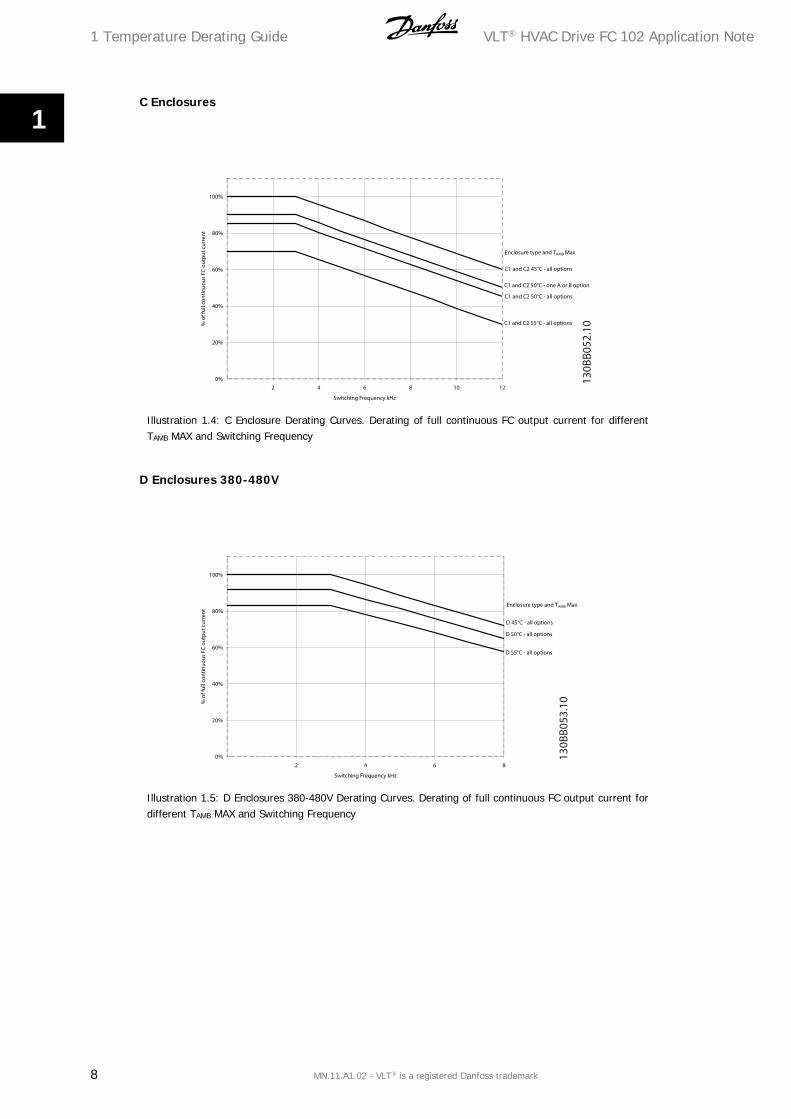
C Enclosures
Illustration 1.4: C Enclosure Derating Curves. Derating of full continuous FC output current for differentTAMB MAX and Switching Frequency
D Enclosures 380-480V
Illustration 1.5: D Enclosures 380-480V Derating Curves. Derating of full continuous FC output current fordifferent TAMB MAX and Switching Frequency
1 Temperature Derating Guide VLT® HVAC Drive FC 102 Application Note
8 MN.11.A1.02 - VLT® is a registered Danfoss trademark
1
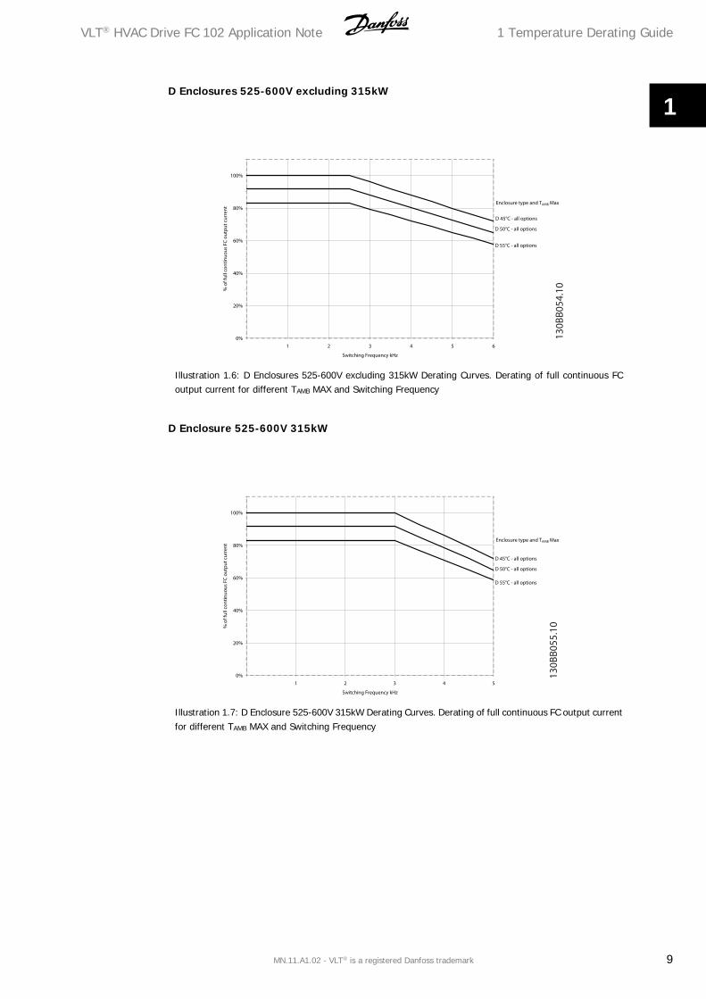
D Enclosures 525-600V excluding 315kW
Illustration 1.6: D Enclosures 525-600V excluding 315kW Derating Curves. Derating of full continuous FCoutput current for different TAMB MAX and Switching Frequency
D Enclosure 525-600V 315kW
Illustration 1.7: D Enclosure 525-600V 315kW Derating Curves. Derating of full continuous FC output currentfor different TAMB MAX and Switching Frequency
VLT® HVAC Drive FC 102 Application Note 1 Temperature Derating Guide
MN.11.A1.02 - VLT® is a registered Danfoss trademark 9
1
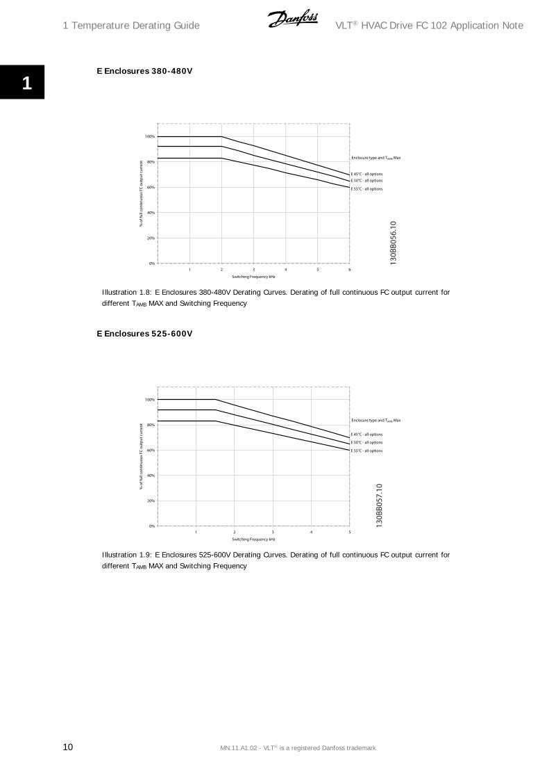
E Enclosures 380-480V
Illustration 1.8: E Enclosures 380-480V Derating Curves. Derating of full continuous FC output current fordifferent TAMB MAX and Switching Frequency
E Enclosures 525-600V
Illustration 1.9: E Enclosures 525-600V Derating Curves. Derating of full continuous FC output current fordifferent TAMB MAX and Switching Frequency
1 Temperature Derating Guide VLT® HVAC Drive FC 102 Application Note
10 MN.11.A1.02 - VLT® is a registered Danfoss trademark
1

1.2.2 Applications with Specific Demands
The curves that follow in this section are applicable for the following applications:
• Screw, Scroll and Reciprocating Compressors where the switching pattern is changedfrom default (i.e. parameter 14-00 is changed to SFAVM).
A Enclosures
Illustration 1.10: A Enclosure Derating Curves. Derating of full continuous FC output current for differentTAMB MAX and Switching Frequency
VLT® HVAC Drive FC 102 Application Note 1 Temperature Derating Guide
MN.11.A1.02 - VLT® is a registered Danfoss trademark 11
1
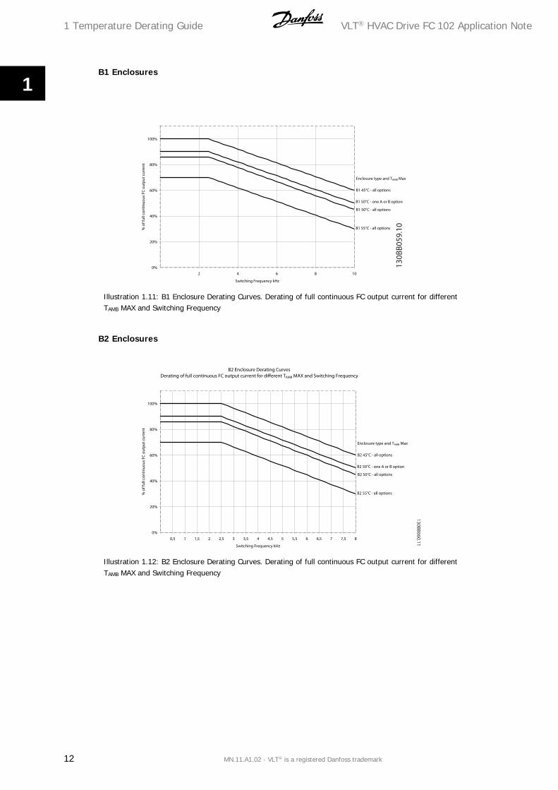
B1 Enclosures
Illustration 1.11: B1 Enclosure Derating Curves. Derating of full continuous FC output current for differentTAMB MAX and Switching Frequency
B2 Enclosures
Illustration 1.12: B2 Enclosure Derating Curves. Derating of full continuous FC output current for differentTAMB MAX and Switching Frequency
1 Temperature Derating Guide VLT® HVAC Drive FC 102 Application Note
12 MN.11.A1.02 - VLT® is a registered Danfoss trademark
1

C Enclosures
Illustration 1.13: C Enclosure Derating Curves. Derating of full continuous FC output current for differentTAMB MAX and Switching Frequency
D Enclosures 380-480V
Illustration 1.14: D Enclosures 380-480V Derating Curves. Derating of full continuous FC output current fordifferent TAMB MAX and Switching Frequency
VLT® HVAC Drive FC 102 Application Note 1 Temperature Derating Guide
MN.11.A1.02 - VLT® is a registered Danfoss trademark 13
1

D Enclosures 525-600V excluding 315kW
Illustration 1.15: D Enclosures 525-600V excluding 315kW Derating Curves. Derating of full continuous FCoutput current for different TAMB MAX and Switching Frequency
D Enclosure 525-600V 315kW
Illustration 1.16: D Enclosure 525-600V 315kW Derating Curves. Derating of full continuous FC output cur-rent for different TAMB MAX and Switching Frequency
1 Temperature Derating Guide VLT® HVAC Drive FC 102 Application Note
14 MN.11.A1.02 - VLT® is a registered Danfoss trademark
1

E Enclosures 380-480V
Illustration 1.17: E Enclosures 380-480V Derating Curves. Derating of full continuous FC output current fordifferent TAMB MAX and Switching Frequency
E Enclosures 525-600V
Illustration 1.18: E Enclosures 525-600V Derating Curves. Derating of full continuous FC output current fordifferent TAMB MAX and Switching Frequency
VLT® HVAC Drive FC 102 Application Note 1 Temperature Derating Guide
MN.11.A1.02 - VLT® is a registered Danfoss trademark 15
1