Embed Size (px)
Citation preview

Issue 1
O U R G E N I U S I S F I T T I N G S
Compression Fittings
Compact Push-in Fittings
Sistem-P Push-in Fittings
Nickel Plated Brass BSP Fittings
Air Valves Silencers Tubing
www.wadefittings.com
Technical Specifications

2Technical Helpline: +44 (0) 1473 277 460
E: [email protected] W: www.wadefittings.com
Technical Specifications
The Wade range is known for its safety
and reliability and includes thousands of
products designed for use on hydraulic and
pneumatic applications within a wide variety
of industries.
Typically they can be found in general use
throughout the automotive, railway, power
generation, instrumentation system, air
conditioning, heating and ventilation, L.P.G.,
leisure, petroleum, oil and gas industries.
They are used on applications where there
is a need for the added safety provided by
an engineering fitting.

3Technical Helpline: +44 (0) 1473 277 460 E: [email protected] W: www.wadefittings.com
Every effort has been made to ensure that the information contained in this publication is accurate at the time of publishing. Wade assumes no responsibility or liability for typographical errors or omissions or for any misinterpretation of the information within the publication and reserves the right to change without notice.
Technical Specifications
MATERIAL STANDARDS FOR WADE MEDIUM PRESSURE BRASS COMPRESSION FITTINGS
Fe Ni Al Cu Pb Sn Others
max 0.3 max 0.3 max 0.05 57 -59 2.5 -3.5 max 0.3 Total 0.2 Zn-remainder
Bar Parts BS-EN 12164:2011 CW614N Chemical composition % of grade CuZn39Pb3 ( CW614N )
Fe Ni Al Cu Pb Sn Others
max 0.3 max 0.3 max 0.05 57 -59 1.6 -2.5 max 0.3 Total 0.2 Zn-remainder
Stampings BS-EN 12165:2011 CW617N Chemical composition % of grade CuZn40Pb2 ( CW617N )
COPPER COMPRESSION RINGS & SEALING WASHERS: BS-EN 12449
Although ‘Wade Couplings’ are primarily designed for use with
copper tubes the range also includes a variety of compression
nuts and rings which provide additional jointing options for;
• PVC covered Copper tubes
• Nylon tube
• Polythene tubes
• Brass tube
• Bundy tube
The standard range is available to suit Imperial and Metric
outside diameter tube sizes from 1/8” to 1” and 4mm to 28mm.
Male and Female stud thread connection options include; BSP
Parallel, BSP Taper and API / NPT from 1/8” to 1”.
Note: Wade coupling bodies are designed for use with
Wade compression nuts and rings. The component parts
are not intended as interchangeable with other brands.
The recommended working pressures for the Wade
brass compression fittings range conform to BS 2051
Part 1 for temperatures up to 65° C. The maximum
recommended working pressures stated apply for use
with Copper and PVC Covered Copper Tubes at ambient
temperature.
Note: if other tube types are used these figures do
not apply and the maximum working pressure and
temperature will be limited by the tubing material, wall
thickness and capability.
Wade brass compression fittings are designed and manufactured
to BS 2051 Part 2 and from material to the following standards;

Technical Helpline: +44 (0) 1473 277 460 E: [email protected] W: www.wadefittings.com
Technical Helpline: +44 (0) 1473 277 460 E: [email protected] W: www.wadefittings.com4
Technical Helpline: +44 (0) 1473 277 460 E: [email protected] W: www.wadefittings.com
Technical Helpline: +44 (0) 1473 277 460 E: [email protected] W: www.wadefittings.com
Every effort has been made to ensure that the information contained in this publication is accurate at the time of publishing. Wade assumes no responsibility or liability for typographical errors or omissions or for any misinterpretation of the information within the publication and reserves the right to change without notice.
Applications
Wade brass compression fittings are designed and manufactured in accordance with BS 2051, for use on hydraulic and pneumatic applications.
With a reputation for safety and reliability, they can be found in general use on installations within the L.P.G., hydraulic, pneumatic, automotive, locomotive, power generation, air compressor, air conditioning, heating, ventilation, oil and gas industries.
Quality
Wade brass compression fittings are manufactured from materials of the following standards:
• Bar Parts-BS EN 12164:2011 CW614N
• Stampings-BS EN 12165:2011 CW617N
• Copper Compression Rings & Sealing Washers-BS EN 12449
Pressure
The recommended working pressures for the Wade range conform to BS 2051 Part 1 for temperatures up to 65° C*. The pressure ratings below apply to Wade Medium Pressure Brass Compression Fittings when used with Copper and PVC Covered Copper Tubes.
*For elevated temperatures please contact the Wade Sales Desk.
Hydraulic Pressures (When used with Copper Tube)
-Imperial
OD Size PSI Bar
1/8” 3045 210
3/16” 3045 210
1/4” 3045 210
5/16” 3045 210
3/8” 2030 140
1/2” 1522 105
5/8” 1522 105
3/4” 1015 70
1” 1015 70
Pneumatic Pressures (When used with Copper Tube)
-Imperial
OD Size PSI Bar
1/8” 1522 105
3/16” 1522 105
1/4” 1522 105
5/16” 1522 105
3/8” 1015 70
1/2” 725 50
5/8” 725 50
3/4” 508 35
1” 508 35
Pneumatic Pressures (When used with Copper Tube)
-Metric
OD Size PSI Bar
4mm 1522 105
5mm 1522 105
6mm 1522 105
8mm 1522 105
10mm 1015 70
12mm 725 50
14mm 725 50
15mm 725 50
16mm 725 50
18mm 508 35
20mm 508 35
22mm 508 35
25mm 508 35
Hydraulic Pressures (When used with Copper Tube)
-Metric
OD Size PSI Bar
4mm 3045 210
5mm 3045 210
6mm 3045 210
8mm 3045 210
10mm 2030 140
12mm 1522 105
14mm 1522 105
15mm 1522 105
16mm 1522 105
18mm 1015 70
20mm 1015 70
22mm 1015 70
25mm 1015 70
For over 60 years the Wade brand has provided high quality, cost effective, brass compression fittings which ensure reliable leak tight joints.
Technical Specifications
MAXIMUM RECOMMENDED WORKING PRESSURES AND TEMPERATURES FOR HYDRAULIC AND PNEUMATIC APPLICATIONS

5Technical Helpline: +44 (0) 1473 277 460
E: [email protected] W: www.wadefittings.comTechnical Helpline: +44 (0) 1473 277 460 E: [email protected] W: www.wadefittings.com
Technical Specifications
Every effort has been made to ensure that the information contained in this publication is accurate at the time of publishing. Wade assumes no responsibility or liability for typographical errors or omissions or for any misinterpretation of the information within the publication and reserves the right to change without notice.
Technical Helpline: +44 (0) 1473 277 460 E: [email protected] W: www.wadefittings.com
Technical Helpline: +44 (0) 1473 277 460 E: [email protected] W: www.wadefittings.com
WADE MEDIUM PRESSURE BRASS COMPRESSION FITTINGS: MAXIMUM RECOMMENDED WORKING PRESSURES AND TEMPERATURES FOR HYDRAULIC AND PNEUMATIC APPLICATIONS
‘Wade Couplings’ are primarily designed for use with copper tubes.
The recommended working pressures for our Wade range conform to BS 2051 Part 1 for temperatures up to 65° C, under essentially vibration free conditions.
The pressure ratings on the previous page apply to Wade Medium Pressure Brass Compression Fittings when used with Copper and PVC Covered Copper Tubes.
Wade Medium Pressure Brass Compression Fittings are suitable for use with Copper Tubes at elevated temperatures from 65° C up to 210° C. If the working temperature exceeds 65° C the ‘Copper Tube Temperature De-Rating Chart’ below should be used in conjunction with the Hydraulic and Pneumatic recommended working pressures detailed on the previous page.
Please note: For use at elevated temperatures, multiply the working pressure by the de-rating factor.
COPPER TUBE TEMPERATURE DE-RATING CHART
0 20 40 60 80 100 120 140 160 180 210
Temperature oC
1.000.900.800.700.600.500.400.300.200.100.00
De-
ratin
g Fa
ctor
6Technical Helpline: +44 (0) 1473 277 460
E: [email protected] W: www.wadefittings.comTechnical Helpline: +44 (0) 1473 277 460 E: [email protected] W: www.wadefittings.com
Every effort has been made to ensure that the information contained in this publication is accurate at the time of publishing. Wade assumes no responsibility or liability for typographical errors or omissions or for any misinterpretation of the information within the publication and reserves the right to change without notice.
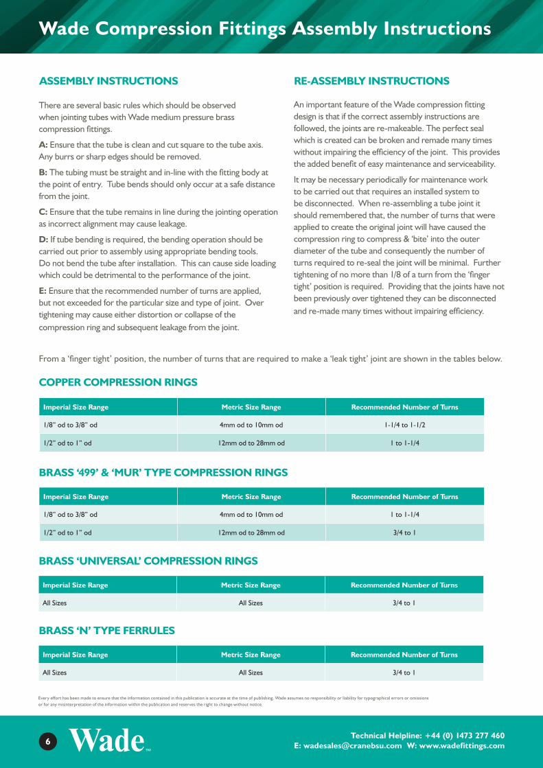
Wade Compression Fittings Assembly Instructions
RE-ASSEMBLY INSTRUCTIONS
From a ‘finger tight’ position, the number of turns that are required to make a ‘leak tight’ joint are shown in the tables below.
Imperial Size Range Metric Size Range Recommended Number of Turns
1/8” od to 3/8” od 4mm od to 10mm od 1-1/4 to 1-1/2
1/2” od to 1” od 12mm od to 28mm od 1 to 1-1/4
COPPER COMPRESSION RINGS
Imperial Size Range Metric Size Range Recommended Number of Turns
1/8” od to 3/8” od 4mm od to 10mm od 1 to 1-1/4
1/2” od to 1” od 12mm od to 28mm od 3/4 to 1
BRASS ‘499’ & ‘MUR’ TYPE COMPRESSION RINGS
Imperial Size Range Metric Size Range Recommended Number of Turns
All Sizes All Sizes 3/4 to 1
BRASS ‘UNIVERSAL’ COMPRESSION RINGS
Imperial Size Range Metric Size Range Recommended Number of Turns
All Sizes All Sizes 3/4 to 1
BRASS ‘N’ TYPE FERRULES
ASSEMBLY INSTRUCTIONS
There are several basic rules which should be observed when jointing tubes with Wade medium pressure brass compression fittings.
A: Ensure that the tube is clean and cut square to the tube axis. Any burrs or sharp edges should be removed.
B: The tubing must be straight and in-line with the fitting body at the point of entry. Tube bends should only occur at a safe distance from the joint.
C: Ensure that the tube remains in line during the jointing operation as incorrect alignment may cause leakage.
D: If tube bending is required, the bending operation should be carried out prior to assembly using appropriate bending tools. Do not bend the tube after installation. This can cause side loading which could be detrimental to the performance of the joint.
E: Ensure that the recommended number of turns are applied, but not exceeded for the particular size and type of joint. Over tightening may cause either distortion or collapse of the compression ring and subsequent leakage from the joint.
An important feature of the Wade compression fitting design is that if the correct assembly instructions are followed, the joints are re-makeable. The perfect seal which is created can be broken and remade many times without impairing the efficiency of the joint. This provides the added benefit of easy maintenance and serviceability.
It may be necessary periodically for maintenance work to be carried out that requires an installed system to be disconnected. When re-assembling a tube joint it should remembered that, the number of turns that were applied to create the original joint will have caused the compression ring to compress & ‘bite’ into the outer diameter of the tube and consequently the number of turns required to re-seal the joint will be minimal. Further tightening of no more than 1/8 of a turn from the ‘finger tight’ position is required. Providing that the joints have not been previously over tightened they can be disconnected and re-made many times without impairing efficiency.

7Technical Helpline: +44 (0) 1473 277 460
E: [email protected] W: www.wadefittings.comTechnical Helpline: +44 (0) 1473 277 460 E: [email protected] W: www.wadefittings.com
Every effort has been made to ensure that the information contained in this publication is accurate at the time of publishing. Wade assumes no responsibility or liability for typographical errors or omissions or for any misinterpretation of the information within the publication and reserves the right to change without notice.
Wade Compression Fitting Jointing Options
Diagram illustrating assembly with Copper Tube using a Copper or Brass Compression Ring
This coupling joint comprises a brass body and compression nut and either an annealed brass (imperial ‘499’ or metric ‘MUR’ type) or copper compression ring. It represents the Wade compression joint in its simplest and most popular form. When correctly assembled it ensures that a perfect seal is obtained. After installation the assembled joint can be disassembled and remade several
times and will provide a sound joint on each occasion. It is important to note that when remaking the joint, the previous assembly will have produced a ‘bite’ onto the tube. Therefore the number of turns required to re-seal the assembly will be minimal. It is recommended that further tightening of approximately 1/8 of a turn from the ‘finger tight’ position, is required to re-create a seal.
WADE COPPER TUBE COUPLING JOINTS: ASSEMBLY INSTRUCTIONS
When using an Imperial or Metric Copper, Brass Imperial ‘499’ or Metric ‘MUR’ type Compression Ring:
Ensure that the tube is cut square to the tube axis and is free from burrs.
Slip the Compression Nut onto the tube followed by the Compression Ring.
Insert the tube into the body of the compression fitting, ensuring that the end of the tube is seated firmly against the internal abutment shoulder.
Finger-Tight (Before Compression)
Spanner-Tight (After Compression)
STANDARD WADE JOINT FOR PLAIN COPPER TUBE

8Technical Helpline: +44 (0) 1473 277 460
E: [email protected] W: www.wadefittings.comTechnical Helpline: +44 (0) 1473 277 460 E: [email protected] W: www.wadefittings.com
Every effort has been made to ensure that the information contained in this publication is accurate at the time of publishing. Wade assumes no responsibility or liability for typographical errors or omissions or for any misinterpretation of the information within the publication and reserves the right to change without notice.
Wade Compression Fitting Jointing Options
Slide the Compression Nut and Ring up to the body and tighten by hand to a ‘finger-tight’ position.
From the ‘finger-tight’ position, using a spanner, tighten the Compression Nut by the recommended number of turns.
COPPER COMPRESSION RINGS
Imperial Size Range Metric Size Range Recommended Number of Turns
1/8” od to 3/8” od 4mm od to 10mm od 1-1/4 to 1-1/2
1/2” od to 1” od 12mm od to 25mm od 1 to 1-1/4
BRASS ‘499’ AND ‘MUR’ TYPE COMPRESSION RINGS
Imperial Size Range Metric Size Range Recommended Number of Turns
1/8” od to 3/8” od 4mm od to 10mm od 1 to 1-1/4
1/2” od to 1” od 12mm od to 25mm od 3/4 to 1

9Technical Helpline: +44 (0) 1473 277 460
E: [email protected] W: www.wadefittings.comTechnical Helpline: +44 (0) 1473 277 460 E: [email protected] W: www.wadefittings.com
Every effort has been made to ensure that the information contained in this publication is accurate at the time of publishing. Wade assumes no responsibility or liability for typographical errors or omissions or for any misinterpretation of the information within the publication and reserves the right to change without notice.
Wade Compression Fitting Jointing Options
The ‘PC’ joint has been designed to enable connection of PVC covered copper tube with standard Wade coupling bodies and compression rings. It is used mainly in chemical and process industries which use PVC covered copper tubes in aggressive environments. The outer PVC cover prevents corrosive atmosphere contacting the copper tubing.
The ‘PC’ compression nut features a chamber and nitrile ‘O’ ring seal within one end, which is designed to both house and protect the outer PVC cover of the tube as it
enters the coupling, preventing atmospheric corrosion and contamination within the joint.
To make the joint the PVC cover should be stripped back to expose a short length of the plain copper tube, (This is the specified ‘P Abutment’ length on ‘PC’ Compression Nut catalogue page). The exposed plain copper section is then pushed through the front of the ‘PC’ compression nut and the joint is made on the tube by the standard Wade method (as explained on the previous pages).
Assembly Instructions: When using an Imperial or Metric Copper, Brass Imperial ‘499’ type or Metric ‘MUR’ type Compression Ring
Ensure that the tube is cut square to the tube axis and is free from burrs.
Cut back the PVC cover, specified in this catalogue as ‘P Abutment’ length on the ‘PC’ Compression Nut dimensional table.
Remove all burrs and sharp edges from the end of the exposed copper tube.
Slip the ‘PC’ Compression Nut onto the tube until the ‘O’ Ring seal grips the PVC cover and slide the Compression Ring onto the exposed copper tube. Insert the tube into the body of the compression fitting, ensuring that the end of the tube is seated firmly against the internal abutment shoulder.
Slide the Compression Nut and Ring up to the body and tighten by hand to a ‘finger-tight’ position.
From the ‘finger-tight’ position, using a spanner, tighten the Compression Nut by the recommended number of turns
Diagram illustrating assembly with PVC Covered Copper Tube using a Copper Compression Ring
Finger-Tight (Before Compression) Spanner-Tight (After Compression)
STANDARD PVC COVERED COPPER TUBE COUPLING JOINT

10Technical Helpline: +44 (0) 1473 277 460
E: [email protected] W: www.wadefittings.comTechnical Helpline: +44 (0) 1473 277 460 E: [email protected] W: www.wadefittings.com
Every effort has been made to ensure that the information contained in this publication is accurate at the time of publishing. Wade assumes no responsibility or liability for typographical errors or omissions or for any misinterpretation of the information within the publication and reserves the right to change without notice.
Wade Compression Fitting Jointing Options
COPPER COMPRESSION RINGS
Imperial Size Range Metric Size Range Recommended Number of Turns
1/4” od to 3/8” od 6mm od to 10mm od 1-1/4 to 1-1/2
1/2” od to 3/4” od 12mm od 1 to 1-1/4
BRASS ‘499’ AND ‘MUR’ TYPE COMPRESSION RINGS
Imperial Size Range Metric Size Range Recommended Number of Turns
1/4” od to 3/8” od 6mm od to 10mm od 1 to 1-1/4
1/2” od to 3/4” od 12mm od 3/4 to 1
STANDARD PVC COVERED COPPER TUBE COUPLING JOINT: AVAILABLE SIZES
Assemblies are available within the Wade range to enable jointing with Imperial and Metric PVC covered copper tubes of the following sizes:
1/4” od Copper Tube with a 1/16” thick PVC cover
3/8” od Copper Tube with a 1/16” thick PVC cover
1/2” od Copper Tube with a 1/16” thick PVC cover
6mm od Copper Tube with a 1.5mm thick PVC cover
8mm od Copper Tube with a 1.5mm thick PVC cover
10mm od Copper Tube with a 1.5mm thick PVC cover
12mm od Copper Tube with a 1.5mm thick PVC cover
Please note, jointing options to suit other copper tube sizes and PVC cover thickness may be available on request.

11Technical Helpline: +44 (0) 1473 277 460
E: [email protected] W: www.wadefittings.comTechnical Helpline: +44 (0) 1473 277 460 E: [email protected] W: www.wadefittings.com
Every effort has been made to ensure that the information contained in this publication is accurate at the time of publishing. Wade assumes no responsibility or liability for typographical errors or omissions or for any misinterpretation of the information within the publication and reserves the right to change without notice.
Wade Compression Fitting Jointing Options
The ‘Universal’ joint has been designed to allow the use of a variety of tube materials with standard Wade coupling bodies and compression nuts. Commonly used with copper and nylon tubes it is also suitable for use with bundy tube. The ‘Universal’ joint provides the end user, distributor and stockist with the option of stocking one assembly suitable for a variety of applications.
The design of the Universal brass compression ring ensures self-alignment when assembled.
This means that the tube can usually be offered into the assembled coupling without removing the compression nut and universal compression ring. Another feature of the design is that there is no requirement for an internal tube support or spigot when used with nylon tube. This means that once the joint has been made there is less restriction within the tube bore ensuring minimum interference to the flow.
ASSEMBLY INSTRUCTIONS: WHEN USING A ‘UNIVERSAL’ COMPRESSION RING
A: Ensure the nylon tube is cut square to the tube axis and is free from burrs.
B: Slip the Compression Nut onto the tube followed by the Compression Ring. The flat face at the top of the ring must sit within the compression nut with the angled end adjacent to the internal seating cone of the fitting body.
C: Insert the tube into the body of the compression fitting, ensuring that the end of the tube is seated firmly against the internal abutment shoulder.
D: Slide the Compression Nut and Ring up to the body and tighten by hand to a ‘finger-tight’ position.
From the ‘finger-tight’ position, using a spanner, tighten the Compression Nut by a recommended 3/4 to 1 full turn.
This applies to all ‘Universal’ Compression Rings within both the imperial and metric Wade range.
Wade Universal Compression Coupling Joint: Available Sizes
Assemblies are available within the Wade range to enable jointing with Imperial and Metric tubes of the following sizes:
1/8” od, 3/16” od, 1/4” od, 5/16” od, 3/8” od,
1/2” od, 4mm od, 5mm od, 6mm od, 8mm od,
10mm od, 12mm od
The Universal compression ring can also be supplied separately enabling conversion of customer’s existing assembled stock. It is important to note that, the universal compression rings are designed for use with standard Wade brass compression bodies and universal compression nuts only, they should not be used with component parts from any other range of products.
• One Ring for most Tube materials
• Self-aligning for quick installation
• Semi push-in feature
• Leak-proof
• Reduced stockholding
• Available in both imperial and metric sizes
Body Universal Ring Universal Nut Tube
WADE UNIVERSAL COMPRESSION COUPLING JOINT
Diagram illustrating assembly with Copper or Nylon Tube using a Universal Brass Compression Ring

12Technical Helpline: +44 (0) 1473 277 460
E: [email protected] W: www.wadefittings.comTechnical Helpline: +44 (0) 1473 277 460 E: [email protected] W: www.wadefittings.com
Every effort has been made to ensure that the information contained in this publication is accurate at the time of publishing. Wade assumes no responsibility or liability for typographical errors or omissions or for any misinterpretation of the information within the publication and reserves the right to change without notice.
Wade Compression Fitting Jointing Options
Diagram illustrating assembly with Nylon Tube using a Brass ‘N’ Type Ferrule:
The Wade brass ‘N’ ferrule and ‘N’ type joint have been designed to allow the use of nylon tube with standard Wade coupling bodies and compression nuts.
To prevent collapse of the nylon tube the design of the ‘N’ ferrule incorporates an internal spigot, providing support to the tube bore with minimum restriction to the flow diameter.
On compression the outer section of the ‘N’ ferrule grips the outside diameter of the nylon tube without undue cutting or distortion into the tube surface.
It is important to ensure that the correct size of ‘N’ ferrule is selected, corresponding to both the outside and inside diameter of the nylon tube being used.
Assembly Instructions: when using an ‘N’ Type Ferrule
Ensure that the nylon tube is cut square to the tube axis and is free from burrs.
Slip the Compression Nut onto the tube and push the ‘N’ ferrule onto the end of the nylon tube.
Finger-Tight (Before Compression)
Spanner-Tight (After Compression)
STANDARD NYLON TUBE ‘N’ TYPE COUPLING JOINT

13Technical Helpline: +44 (0) 1473 277 460
E: [email protected] W: www.wadefittings.comTechnical Helpline: +44 (0) 1473 277 460 E: [email protected] W: www.wadefittings.com
Every effort has been made to ensure that the information contained in this publication is accurate at the time of publishing. Wade assumes no responsibility or liability for typographical errors or omissions or for any misinterpretation of the information within the publication and reserves the right to change without notice.
Wade Compression Fitting Jointing Options
Insert the tube and ‘N’ ferrule into the body of the compression fitting.
Slide the Compression Nut up to the body and tighten by hand to a ‘finger-tight’ position.
From the ‘finger-tight’ position, using a spanner, tighten the Compression Nut by a recommended 3/4 to 1 full turn. This applies to all ‘N’ ferrules within both the imperial and metric Wade range.

14Technical Helpline: +44 (0) 1473 277 460
E: [email protected] W: www.wadefittings.comTechnical Helpline: +44 (0) 1473 277 460 E: [email protected] W: www.wadefittings.com
Every effort has been made to ensure that the information contained in this publication is accurate at the time of publishing. Wade assumes no responsibility or liability for typographical errors or omissions or for any misinterpretation of the information within the publication and reserves the right to change without notice.
Wade Compression Fitting Jointing Options
Diagram illustrating assembly with Poly Tube using Brass ‘P’ Type Brass Spigot, Knurled Compression Nut and Polythene Compression Ring
Finger-Tight (Before Compression) Spanner-Tight (After Compression)
The Wade ‘P’ type joint have been designed to allow standard Wade compression coupling bodies to be adapted for use with Polythene tube.
The ‘P’ joint incorporates a brass spigot which provides an internal tube support, a polythene compression ring and a brass compression nut with a knurled external surface.
The joint is made by hand tightening the knurled compression nut which causes the polythene compression ring to grip the poly tube to achieve a perfect seal.
Assembly components required to make the Wade ‘P’ type joint:
Assembly Instructions: when using a Polythene ‘P’ Type Compression Ring
Ensure that the tube is cut square to the tube axis and is free from burrs.
Insert the brass spigot into the body of the compression fitting making sure that it is in line with the axis of the body. Slip the knurled Compression Nut onto the tube followed by the polythene Compression Ring.
Slide the Compression Nut and Ring up to the body and tighten by hand to a ‘finger-tight’ position.
Standard Brass Coupling Body
Brass Spigot
Brass ‘P’ Nut
Polythene Ring
From the ‘finger-tight’ position, fully tighten the knurled Compression Nut by hand
Push the end of the tube over the spigot. It is important to ensure that the end of the tube is seated fully over the spigot.
STANDARD POLY TUBE ‘P’ TYPE COUPLING JOINT

15Technical Helpline: +44 (0) 1473 277 460
E: [email protected] W: www.wadefittings.comTechnical Helpline: +44 (0) 1473 277 460 E: [email protected] W: www.wadefittings.com
Technical Specifications
Every effort has been made to ensure that the information contained in this publication is accurate at the time of publishing. Wade assumes no responsibility or liability for typographical errors or omissions or for any misinterpretation of the information within the publication and reserves the right to change without notice.Every effort has been made to ensure that the information contained in this publication is accurate at the time of publishing. Wade assumes no responsibility or liability for typographical errors or omissions or for any misinterpretation of the information within the publication and reserves the right to change without notice.
THREAD TYPES FOR STANDARD WADE COMPRESSION ENDS
The standard compression ends on Wade Medium Pressure Brass Compression Fittings feature parallel male threaded bodies and parallel female threaded compression nuts. Compression ends to suit imperial outside diameter tube sizes are generally BSP threads. For metric outside diameter tube sizes the compression ends have metric threads.
Thread types and sizes of standard Imperial and Metric Wade compression ends are confirmed in the tables below.
The recommended hole diameters to be drilled through a panel to house a Wade bulkhead fitting with these compression ends and threads are detailed in the right hand column.
Imperial Sizes Thread Recommended Hole Diameter
1/8” OD 1/8” BSP 25/64” (0.391”)
3/16” OD 1/8” BSP 25/64” (0.391”)
1/4” OD 1/4” BSP 17/32” (0.531”)
5/16” OD 1/4” BSP 17/32” (0.531”)
3/8” OD 3/8” BSP 43/64” (0.672”)
1/2” OD 1/2” BSP 27/32” (0.844”)
5/8” OD 3/4” BSP 1 -1/16” (1.062”)
3/4” OD 7/8” BSP 1 -13/64” (1.203”)
7/8” OD 1” BSP 1 -21/64” (1.328”)
1” OD 1.461 x 11 WHIT 1 -15/32” (1.469”)
Metric Sizes Thread Recommended Hole Diameter
4mm OD M8 x 1 9mm
5mm OD M10 x 1 11mm
6mm OD M10 x 1 11mm
8mm OD M12 x 1 13mm
10mm OD M16 x 1.5 17mm
12mm OD M18 x 1.5 19mm
14mm OD M20 x 1.5 21mm
15mm OD M20 x 1.5 21mm
16mm OD M22 x 1.5 23mm
18mm OD M24 x 1.5 25mm
20mm OD M27 x 1.5 28mm
22mm OD M30 x 1.5 31mm
25mm OD M33 x 1.5 34mm
28mm OD M36 x 1.5 37mm

16Technical Helpline: +44 (0) 1473 277 460
E: [email protected] W: www.wadefittings.comTechnical Helpline: +44 (0) 1473 277 460 E: [email protected] W: www.wadefittings.com
Every effort has been made to ensure that the information contained in this publication is accurate at the time of publishing. Wade assumes no responsibility or liability for typographical errors or omissions or for any misinterpretation of the information within the publication and reserves the right to change without notice.
Check List
BSP Parallel Male
BSP Parallel Female
BSP Taper Male
BSP Taper Female
API (NPT) Male
API (NPT) Female
Other Type? (Please Specify)
WADE ENQUIRY SPECIFICATION QUESTIONNAIRE:
To enable us to identify the correct Wade product please confirm:
What is the configuration of the fitting?
Straight (In-line)
90˚ Elbow
Tee
Other Type? (Please Specify)
What is the compression end size?
What is the stud thread connection size?
What is the stud thread connection type?
Specification
What is the application?
What is the flow medium? What is the working pressure?
Hydraulic Pneumatic
What is the outside diameter of the tubing? What is the working temperature?
What is the material of the tubing being jointed?
Application

17Technical Helpline: +44 (0) 1473 277 460
E: [email protected] W: www.wadefittings.comTechnical Helpline: +44 (0) 1473 277 460 E: [email protected] W: www.wadefittings.com
Every effort has been made to ensure that the information contained in this publication is accurate at the time of publishing. Wade assumes no responsibility or liability for typographical errors or omissions or for any misinterpretation of the information within the publication and reserves the right to change without notice.
1. What Quality standard do you have currently in place for Wade?
The design, capability & performance are in accordance with BS2051 parts 1& 2. There are also additional material standards with regards to the construction.
2. What materials and standards do we manufacture Wade brass compression fittings from? This information can be found on Page 4: ‘Technical Information and Standards’.
3. What types of pipe can Wade fittings be used with?
Wade fittings are primarily designed for use with copper tubes but covered for:
i. PVC covered copper tubeii. Nylon tubeiii. Polythene tubeiv. Brass & Bundy tube
4. How long can the Wade Fittings last?
Wade fittings are designed to be long standing, but the working conditions, pressure, temperatures, flow medium and installation environment will impact these. For more information on specific items please contact the Sales Team on 01473 277 460.
5. Do I need tools to connect Wade fittings?
Wade fittings are designed for use with standard tools. Normally set spanners (not adjustable) would be used to make the joints. The simple design principle enables quick and easy installation with no requirement for special installation skills.
6. Is a Wade fitting re-usable?
Joints are designed to be re-makeable. Correct assembly creates a perfect seal that can be broken and remade without impairing the efficiency of the joint. This enables easy maintenance and serviceability. In addition, if a system needs to be dismantled and replaced with new tubing it should be possible to re-use the existing component bodies (as long as they have not been damaged) and re-assemble with replacement compression nuts and rings.
7. Can a Wade fitting be rotated on the pipe?
Once installed, Wade compression fittings should not be ‘rotated’ on the pipe. To rotate a fitting, you would need to relax the joint and break the seal.
8. What are the maximum temperature and pressure ratings for Wade fittings?
The maximum working temperature for a Wade brass compression fitting is:
• 210 ° C if used with Copper tube• 80 ° C if used with Nylon tube• 60 ° C if used with Polythene tube
FAQ’s

18Technical Helpline: +44 (0) 1473 277 460
E: [email protected] W: www.wadefittings.comTechnical Helpline: +44 (0) 1473 277 460 E: [email protected] W: www.wadefittings.com
14. Sales - Who do I need to contact if I require products from our other Crane brands.
For information on the other Crane brands which are available from our Hitchin site, please refer to the contact list below:
13. I can’t find the parts I need in this catalogue, who do I contact?
Please contact our Sales Team on 01473 277 460 or email [email protected]
01462 443277 or [email protected]
01473 277300 or [email protected]
01473 277410 or [email protected]
01462 443 220 or [email protected]
01462 443278 or [email protected]
01462 443131 or [email protected]
01462 443277 or [email protected]
01462 443 226 or [email protected]
01462 443 225 or [email protected]
01462 443322 or [email protected]
The maximum pressure rating is dependent on a combination of factors:
• Tube size• Working pressure• Working temperature• Application: Hydraulic or Pneumatic
The smaller the size the higher the pressure. The pressure rating for a hydraulic application is approximately double the pressure rating for a pneumatic application.
10. What are the available set pressures for Wade Safety Relief Valves?
Wade safety relief valves are available at set pressures within a range from 1.8 to 20.1 Bar.
11. How long will it take for my products to be delivered?
The majority of our products are existing stock, please contact the Sales Team on 01473 277 460 and they will confirm an accurate lead time for your products.
12. What are the applications where Wade Fittings are used?
a. Hydraulic applications: Confirmation of the maximum recommended working pressures and temperatures for Wade brass compression fittings used with copper tube on hydraulic applications can be found on pages 116 and 117
b. Pneumatic applications: Confirmation of the maximum recommended working pressures and temperatures for Wade brass compression fittings used with copper tube on pneumatic applications can be found on pages 116 and 117
FAQ’s
18

To visit our Video Library go to: www.youtube.com/user/CraneBSU
CRANE HOUSE, EPSILON TERRACEWEST ROAD, IPSWICHSUFFOLK, IP3 9FJ,UNITED KINGDOM TELEPHONE: +44 (0)1473 277460FAX: +44 (0)1473 277411 EMAIL: [email protected]
FM311ISO 9001
www.wadefittings.com
www.cranebsu.com
• Designed and manufactured under quality management systems in accordance with BS EN ISO 9001-2008
Every effort has been made to ensure that the information contained in this publication
is accurate at the time of publishing. Wade assumes no responsibility or liability for
typographical errors or omissions or for any misinterpretation of the information within
this publication and reserves the right to change without notice. We hope that our
communications have an impact on you, but not on the environment. We have taken
steps to ensure this leaflet is printed on FSC material and the paper is made by a totally
chlorine free process. W_P
D_1
0_20
15