Embed Size (px)
Citation preview
1
STONE MASONRY CONFINEMENT WITH FRP AND FRCM COMPOSITES 1
L. Estevana, F.J. Baezaa, D. Brua, S. Ivorraa,* 2
a Department of Civil Engineering, University of Alicante, P.O. Box 99, 03080 – Alicante, Spain 3
* Corresponding author [email protected] 4
ABSTRACT 5
In the last decades, there are many reports on the use of composites as reinforcement of structural 6
elements under compression, especially regarding the confinement of concrete structures, but works 7
on stone or masonry columns are limited. Initially, FRP jackets were used because their high 8
structural performance. However, they present some drawbacks like aesthetics or water 9
impermeability, which can affect their applicability in historical constructions made in stone. 10
Recently, FRCM appeared as an alternative with better compatibility with masonry structures. In 11
the present study, a comparison between different composite materials to confine masonry 12
specimens was made. FRPs with carbon or glass fibers and epoxy matrix, and FRCM with basalt or 13
glass fiber mesh in a cementitious matrix were used to confine masonry, made in calcarenite 14
cylindrical pieces and lime mortar. Strength and ductility gains under compressive loads were 15
measured, and compared to the recommendations of different guidelines. Unidirectional FRPs were 16
the optimal solution from a strengthening point of view. On the other hand, FRCM confinement 17
offered more ductility than unreinforced masonry, but showed a softening behavior. Finally, 18
regarding the studied design codes, the specific parameters included for masonry structures seemed 19
enough to obtain accurate predictions of the compressive strength increase due to the confinement 20
with the tested composites. 21
Keywords: masonry, stone, confinement, FRP, FRCM, TRM. 22
1. INTRODUCTION 23
A great deal of the built architectural heritage is made in stone and masonry structural systems. 24
These structures require retrofitting or reinforcement solutions because of the natural degradation of 25
materials, service load changes due to new use, or even to improve the structural response after or 26
in case of extraordinary events, such as fires or earthquakes. In those cases, lateral confinement 27
2
could be a suitable solution to gain mechanical strength in columns under longitudinal compression. 28
Traditionally, these reinforcements have been designed using steel profiles. However, composites 29
appeared as an alternative that has been proven successful [1,2]. Composite reinforcements present 30
several advantages, like low self-weight, low maintenance cost and high durability. In addition, they 31
can easily adapt to the external shape of the reinforced element for a less intrusive solution. 32
Nowadays, composites for this type of reinforcement can be classified in two categories depending 33
on the nature of the matrix, polymer or cement. The former, fiber reinforced polymers (FRP) 34
usually use epoxy resins. The latter use modified cement mortars, and are known as fabric 35
reinforced cementitious matrix (FRCM), also identified in scientific literature as textile reinforced 36
mortars (TRM). The use of FRPs in the rehabilitation of civil engineering structures started in the 37
early 1990’s [3]. However, in the particular case of heritage constructions, FRCM solutions are 38
recently gaining weight because they present better compatibility with the stone or masonry 39
substrate, and unlike FRP systems based on epoxy resins FRCM layers are permeable coatings in 40
structures with damp or humidity problems [4-6]. 41
Since 1990’s, many researchers focused on the effect of FRP jackets to improve the strength of 42
concrete columns [7-11]. These works led to the formulation of different confinement models to 43
simulate the behavior of confined concrete elements with great accuracy [12-14]. On the other hand, 44
FRCM reinforcements have been developed recently, thus there are few reports regarding their use 45
[15-18], and the behavior models are still to be perfectly adapted, especially compared to the 46
confinement with FRP [19]. Nonetheless, most of the research on confinement with either FRCM or 47
FRP has been focused on concrete reinforcement, but some references can be found regarding the 48
effect on masonry or stone elements. 49
The experimental evaluation of FRP solutions for the confinement of masonry or stone columns has 50
been made considering different sections and ratios, several types of rock, or even with non-51
continuous reinforcements. Aiello et al. [20,21] studied the confinement of calcareous rock 52
specimens with circular or rectangular cross sections. In these cases, the reinforcement was made in 53
3
carbon or glass fiber fabrics (CFRP or GFRP respectively), which were casted as continuous jackets 54
or narrower horizontal stripes with different widths and separations. Continuous FRP jackets 55
increased 93% the strength of the bare masonry, with 200% increase of the ultimate strain. On the 56
other hand, non-continuous confinements may produce the failure of the unreinforced part of the 57
specimen, but if the separation between FRP stripes was limited the performance was similar than a 58
continuous FRP jacket. Faella et al. [22] studied CFRP and GFRP reinforcements, but in specimens 59
from different types of stone (calcareous and volcanic). Both of these confined stones presented a 60
bilinear stress-strain curve, but the transition point between different stiffness changed. In the 61
confinement of the volcanic rock (with lower strength), this transition was detected at the strength 62
of the bare rock, while it appeared at almost twice the strength of calcareous samples. Micelli et al. 63
[23] made a study similar to [20] but, in addition to FRP jackets, including also reinforcements of 64
FRCM or shape memory alloys (in which an active confinement could be achieved). The 65
confinement solutions using FRCM produced a smaller strength gain than FRP alternatives. 66
However, FRCM confinements led to a more ductile behavior, avoiding the brittle failure of the 67
unreinforced masonry. Witzany & Zigler [24,25] tested large scale masonry columns made with 68
regular rectangular stone elements or irregular pieces. In these cases, the confinement was 69
discontinuous and made using horizontal CFRP stripes. A loss of efficiency of the confinement was 70
related to the rectangular cross-section of the specimens or the discontinuous configuration of the 71
confinement. Estevan et al. [26,27] evaluated the effectiveness of CFRP and GFRP continuous 72
jackets in confined rock cylindrical specimens after being exposed to high temperatures inside an 73
oven or using real fire. In these damaged samples, the FRP confinement was capable of achieving 74
strength values similar to undamaged specimens confined with the same material. Regarding the 75
effect of FRCM confinement of masonry elements, few references can be found [28-31]. Finally, 76
the available confinement models for FRP or FRCM jackets and stone or masonry columns are very 77
scarce at the moment and, in fact, are an adaptation of concrete models, in which some parameters 78
have been modified [32,33]. As a summary of these references, in general, the effect of jacketing 79

4
with composites on the mechanical performance of masonry specimens has been observed in the 80
increase of their compressive strength (up to three times the strength of unreinforced masonry 81
depending on the properties of the composite), and higher ductility related to the increase of the 82
ultimate strain of the confined masonry. The effectiveness of the confinement may be compromised 83
in elements with rectangular cross section, because the stress concentration in the corners reduces 84
the confinement efficiency, but may be controlled modifying the curvature of the corners. Besides, 85
similar strengthening ratios can be obtained even with discontinuous jackets, in which the distance 86
between consecutive strips should be controlled to obtain an adequate confinement level. 87
Considering the aforementioned references as a representation of the scientific production in this 88
particular matter (confinement of masonry columns using FRP and FRCM), similar limitations can 89
be found in the recommendations included in the structural design codes of different countries [34-90
39]. Most of them have considered almost exclusively the confinement of concrete structures. Only 91
the Italian guides, CNR-DT 200 R1/2013 [34] and the recently published CNR-DT 215/2018 [35], 92
make particular considerations for masonry columns and FRP or FRCM confinements, respectively. 93
In both cases, the constitutive laws for confined specimens are analogue to concrete models with 94
slight modifications. 95
Therefore, the main objective of the current work was aimed at the confinement of cylindrical stone 96
masonry specimens using composite materials (FRP or FRCM jackets). As presented before, there 97
is a lack of references covering this topic, because they are often focused on concrete reinforcement 98
instead of stone or brick masonry. In this case, stone specimens were fabricated with three 99
cylindrical pieces and lime mortar. Afterwards, composite jackets with different fibers and matrices 100
were casted (epoxy resin with carbon or glass fibers, and cement matrix with glass or basalt fiber 101
mesh) to determine the efficacy of each system. In addition, the experimental results have been 102
compared to the predictions based on the recommendations of the Italian guides [34,35], which are 103
the only two that consider specific expressions and coefficients for masonry elements. The stone 104

5
samples for this research were calcarenites (San Julian’s stone), which was used in the construction 105
of the most important historical buildings in the city of Alicante (Spain). 106
2. MATERIALS AND METHODS 107
2.1. Characterization of materials and specimens 108
The stone samples used in the fabrication of the masonry specimens were obtained from a railway 109
tunnel excavation, under a former quarry near the sea in Alicante (Spain). From the geotechnical 110
survey materials, a total number of 96 calcarenite pieces with cylindrical shape (83 mm diameter 111
and 70 mm high) were selected. Each masonry specimen comprised three of those stone pieces and 112
4 mm thick mortar joints between them. Therefore, the dimensions of each test specimen were a 113
diameter of 83 mm and a height of 218 mm. The slenderness of the samples, height/diameter ratio, 114
was 2.63, between the recommended values of 2.5 and 3 in the standards for compression tests. In 115
addition, one-piece rock samples with 72 mm diameter and 180 mm height were also prepared in 116
order to characterize the mechanical and physical properties of the rock, according to the 117
procedures in ASTM D7012-14e1 [40]. The average ± standard deviation values of four samples 118
were: bulk density 1982 ± 28 kg/m³; compressive strength 19.99 ± 1.61 N/mm²; modulus of 119
elasticity 11859 ± 475 N/mm²; Poisson’s ratio 0.22 ± 0.03. For additional information on the 120
mechanical performance of this rock refer to the following references [41,42]. The lime mortar for 121
the joints was a commercial mixture (53% aggregates and 47% natural lime), with water/binder 122
ratio of 0.60, and a 7.5 N/mm² minimum compressive strength after 28 days, according to the 123
supplier. Figure 1 includes an example of the masonry preparation process and the whole set of 32 124
samples, which were kept in laboratory conditions for 18 months before casting the FRP or FRCM 125
confinement. 126
Masonry confinement was made with two different types of composite: fiber reinforced polymers 127
(FRP) and fabric reinforced cementitious matrix (FRCM). Three different fabrics were used for the 128
FRP: unidirectional carbon fiber, unidirectional glass fiber and quadraxial glass fiber, as shown 129
respectively in Figure 2 (a), (b) and (c), all of them with an epoxy resin matrix. On the other hand, 130

6
FRCM included two different reinforcements, glass fiber mesh (Figure 2(d)) or basalt fiber mesh 131
(Figure 2(e)), and a cement based mortar matrix. 132
(a)
(b)
Fig. 1. Stone masonry preparation: (a) lime mortar and vertical alignment; (b) 32 masonry specimens before 133
reinforcement. 134
(a)
(b)
(c)
(d)
(e)
Fig. 2. Fabrics for the FRP reinforcements: (a) unidirectional CFRP; (b) unidirectional GFRP; (c) quadraxial 135
GFRP. Meshes for FRCM jackets: (d) glass fiber mesh; (e) basalt fiber mesh. 136
The mechanical properties of each composite were measured in direct tensile tests in order to obtain 137
the elastic modulus and tensile strength. Therefore, 15 FRP specimens were prepared, five per each 138
FRP type, in which tensile tests were made according to ASTM D7565/D7565M-10 (2017) [43]. 139
Figure 3 includes the stress-strain results for each sample (CU carbon uniaxial, GU glass uniaxial 140
and GM glass multiaxial); while Table 1 summarizes the mechanical properties for the raw 141
materials (fabrics and resin) according to the supplier, and the composite’s properties measured 142
experimentally (average values and coefficient of variation for five samples are given). CFRP 143
samples presented the highest strength and stiffness, 637 MPa and 56 GPa, both calculated with 144
respect to the gross cross section as ASTM D7565 requires [43]. Uniaxial GFRP achieved almost 145

7
the same strength level, 539 MPa, because the fabric’s weight was higher (900 g/m²). They also 146
showed higher elongation at failure than their CFRP counterparts did, 2.21% against 1.16%. On the 147
other hand, despite the higher fiber dosage of multiaxial fabric (1140 g/m²), these composites 148
presented the lowest mechanical performance because the dimensions and orientation of fibers 149
reduced their efficiency. 150
151
Fig. 3. Stress vs strain results measured in uniaxial tension tests according to ASTM D7565/D7565M-10 152
(2017) for different FRP types: uniaxial CFRP (CU), uniaxial GFRP (GU), and multiaxial GFRP (GM). 153
Table 1. Main properties of FRP raw materials and composite specimens. 154
Fabric 1 Epoxy resin 1
Composite 2
CU GU GM CU GU GM Weight (g/m2) 300 900 1140 - - - - Thickness (mm) 0.166 3 0.480 3 0.438 3 - 0.81 4
(12.54%) 1.08 4
(3.36%) 1.27 4
(2.21%) Tensile strength (MPa) 4830 2560 2600 40 637
(6.43%) 539
(7.48%) 184
(5.50%) Elastic modulus (MPa) 230000 80700 73000 1400 56078
(7.60%) 25344
(6.06%) 8170
(5.12%) Ultimate strain (%) 2 3 - 4 3.5 - 4 1.8 1.16
(6.01%) 2.21
(5.15%) 2.09
(8.89%) 1 Values provided by supplier. 2 Experimental average values from uniaxial tensile tests (coefficient of variation, in brackets). 3 Dry fabric thickness. 4 Composite thickness, measured with micrometer. For the mechanical properties of FRCM, five coupons of each type were fabricated with dimensions 155
400x100x9 mm (length x width x thickness). Two different meshes, glass and basalt fibers, were 156
used, both in a cement mortar matrix. The mechanical properties of these three materials as given 157
by the supplier have been included in Table 2. In this case, tensile tests were made following the 158
procedure included in AC434 [44]. The experimental configuration can be observed in Figure 4 (a) 159
and (b), in which the elongation was measured with one LVDT. The mechanical behavior of FRCM 160
8
was quite different than FRPs, as shown in Figure 4(c). The idealized behavior included in AC434 161
[44] is modeled as a bilinear function, which is comprised of an initial elastic response until the 162
cement matrix begins to crack, and after this transition point (T) a strengthening phase may appear 163
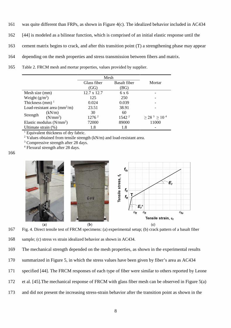
depending on the mesh properties and stress transmission between fibers and matrix. 164
Table 2. FRCM mesh and mortar properties, values provided by supplier. 165
Mesh
Mortar Glass fiber (GG)
Basalt fiber (BG)
Mesh size (mm) 12.7 x 12.7 6 x 6 - Weight (g/m2) 125 250 - Thickness (mm) 1 0.024 0.039 - Load-resistant area (mm2/m) 23.51 38.91 -
Strength (kN/m) 30 60 (N/mm2) 1276 2 1542 2 ≥ 28 3 ≥ 10 4
Elastic modulus (N/mm2) 72000 89000 11000 Ultimate strain (%) 1.8 1.8 - 1 Equivalent thickness of dry fabric. 2 Values obtained from tensile strength (kN/m) and load-resistant area. 3 Compressive strength after 28 days. 4 Flexural strength after 28 days.
166
(a)
(b)
(c)
Fig. 4. Direct tensile test of FRCM specimens: (a) experimental setup; (b) crack pattern of a basalt fiber 167
sample; (c) stress vs strain idealized behavior as shown in AC434. 168
The mechanical strength depended on the mesh properties, as shown in the experimental results 169
summarized in Figure 5, in which the stress values have been given by fiber’s area as AC434 170
specified [44]. The FRCM responses of each type of fiber were similar to others reported by Leone 171
et al. [45].The mechanical response of FRCM with glass fiber mesh can be observed in Figure 5(a) 172
and did not present the increasing stress-strain behavior after the transition point as shown in the 173

9
idealized model of Figure 4(c). Instead, a transition zone appears at a maximum stress of 1200 MPa 174
(approx.), which coincided with the cement matrix cracking, and was very close to the strength of 175
the glass fibers. Afterwards, the progressive failure of each fiber occurred, with different softening 176
curves depending on the actual loading conditions of each particular specimen. On the other hand, 177
basalt fiber FRCM shown in Figure 5(b) presented a bilinear behavior similar to the model in 178
AC434 [44], in which the transition point can be clearly detected and all fibers broke at once. In this 179
case, elongation at failure was almost ten times the elongation corresponding to the transition point. 180
Therefore, the reinforcement effect of the fiber mesh was perfectly registered, unlike glass fiber 181
specimens. Table 3 summarizes all the experimental results of both FRCM according to the 182
indications in AC434 [44], besides the average values of five tested samples, the corresponding 183
coefficient of variation is given in brackets. 184
(a)
(b)
Fig. 5. Tensile test results, stress vs strain of FRCM specimens with (a) glass fiber mesh (GG) or (b) basalt 185
fiber mesh (BG). 186
Table 3. FRCM properties, experimental values from uniaxial tensile tests 1. 187
FRCM fft (MPa) εft Ef * (MPa) ffu (MPa) εfu Ef (MPa) GG 2 2 1393 (6.93%) 1474 (4.10%) 0.00273 (13.88%) 2
BG 638 (8.20%) 0.00074 (22.35%) 1128 (12.01%) 1177 (6.53%) 0.01771 (8.52%) 38510 (9.30%) 1 Notation from AC434, Figure 4 (c); coefficient of variation, in brackets. 2 Unreliable values, according to stress-strain curves.

10
2.2. Experimental campaign and test setup 188
Uniaxial compression tests were performed in 32 masonry samples, which have been divided into 8 189
different sets, each one with a different type of reinforcement, as shown in Table 4. The 190
identification of each sample was made using a six-character code: AA.BB.XX, in which: 191
• AA referred to the confinement material: N (non-reinforced), CU (uniaxial CFRP), GU (uniaxial 192
GFRP), GM (quadraxial GFRP), GG (glass fiber FRCM) or BG (basalt fiber FRCM). 193
• BB referred to the number of reinforcement layers: one layer or three layers. 194
• XX referred to the identification number of the specimens in each set, i.e. 01, 02, 03 or 04. 195
Figure 6(a) summarizes the FRP reinforcement process, which included: (i) the preparation of the 196
surface with a steel brush and the use of compressed air to remove any loose particles. (ii) 197
Afterwards, the first epoxy layer was brushed all over the lateral surface. (iii) Then the fabric was 198
aligned with the transverse direction of the sample, and to avoid bonding problems a 25% overlap 199
(65 mm) was set. (iv) Finally, lateral pressure to the fabric was applied with an aluminum roller to 200
make the resin flow through the fibers, and the rest of the epoxy was applied at the same time. Once 201
the FRP was casted, samples were kept in laboratory conditions for 7 days to cure at approximately 202
20°C. 203
Table 4. Specimen’s identification and characteristics of the reinforcement. 204
Set Label 1 Reinforcement Layers Samples 01 N.00.XX - - 4 02 CU.01.XX CFRP, uniaxial 1 4 03 GU.01.XX GFRP, uniaxial 1 4 04 GM.01.XX GFRP, quadraxial 1 4 05 GG.01.XX FRCM, glass fiber mesh 1 4 06 GG.03.XX FRCM, glass fiber mesh 3 4 07 BG.01.XX FRCM, basalt fiber mesh 1 4 08 BG.03.XX FRCM, basalt fiber mesh 3 4
1 4 samples per set (XX = 01, 02, 03, 04) 205
On the other hand, the procedure to confine with FRCM was slightly different, as shown in Figures 206
6(b) and (c). The initial surface treatment was analogue to the one in FRP confined samples (steel 207
brush and compressed air). Before casting the first mortar layer, samples were water-sprayed to 208
avoid that rock specimens absorbed water from the mortar of the FRCM. The FRCM jacket was 209

11
casted in three steps: initial mortar layer, 3-4 mm thick; fiber mesh with 50% overlap (130 mm); 210
and second mortar layer 3-4 mm thick. The fresh mortar was finished with a spatula, and in 211
addition, at both ends of the specimen, the mortar was removed in the first 5 mm (Figure 6(c)) in 212
order to avoid direct vertical compression in the jacket during the loading of masonry samples. 213
Finally, samples were kept in laboratory conditions for 28 days. All prepared samples with different 214
reinforcements are shown in Figure 7(a). 215
(a)
(b)
(c)
Fig. 6. Reinforcement of masonry samples with composites: (a) FRP confinement; (b) mortar and fiber mesh 216
of FRCM confinement, and (c) end faces for a proper load application. 217
(a)
(b)
Fig. 7. Test procedure: (a) general view of the 32 tested samples with different reinforcements; (b) 218
longitudinal compression test setup. 219
All samples were tested under uniaxial compression in an electromechanical press with a load cell 220
with maximum capacity of 300 kN. Tests were made at a fixed loading rate of 0.5 MPa/s, according 221
to the recommendations in ASTM D7012-14e1 [40]. An example of the experimental setup is 222
shown in Figure 7(b), in which the upper ball and joint guarantees the load alignment, two LVDTs 223
were used to register vertical deformations, and two longitudinal strain gages were attached to the 224

12
middle section to monitor transverse strains. A data monitoring device, HBM Spider with Catman 225
software, was used to register all channels at 2 Hz frequency. 226
3. EXPERIMENTAL RESULTS AND DISCUSSION 227
Different confinement solutions using FRP and FRCM with several types of fiber, as detailed 228
above, were tested under uniaxial compression to discuss the efficiency of each material in terms of 229
strength increase and ductility. During every test deformations were monitored, longitudinal values 230
were measured using LVDTs, while two strain gages were used in transverse direction. However, 231
in the following discussion only longitudinal strain versus compressive stress curves have been 232
represented for a proper mechanical performance analysis. The transverse strain data have been 233
included only in tables and were used in the analytical study based on different design codes. All 234
the stress-strain curves of masonry specimens below include a thick black curve for the average 235
stress value (4 samples in each set), and a grey-shadowed area corresponding to the 95% 236
bidirectional confidence interval for the stress measure at each strain level. These confidence 237
intervals were calculated according to UNE 66040:2003 [46] and have been only represented in the 238
strain range with at least three measures. In the graphs of confined samples, the average curve 239
corresponding to unreinforced masonry has been also included for a better comparison. During the 240
discussion and analyses, the following notation was used: 241
fmo Peak compressive strength of unreinforced masonry (MPa) 242
fmc Peak compressive strength of confined masonry (MPa) 243
εmo Strain at failure of unreinforced masonry (longitudinal) 244
εmc Strain at failure of confined masonry (longitudinal) 245
εmo,t Strain at failure of unreinforced masonry (transverse) 246
εmc,t Strain at failure of confined masonry (transverse) 247
εfu Strain at failure of the FRP or FRCM, obtained in direct tensile tests 248
gm Unreinforced masonry mass-density (kg/m³) 249

13
Em Modulus of elasticity of the unreinforced masonry (MPa), determined as the average slope 250
of the straight-line portion of the stress-strain curve [40] 251
3.1. Unconfined columns 252
Table 5 includes a summary of the mechanical properties measured in unreinforced masonry 253
specimens. For each property, the average value and the coefficient of variation (in brackets, as 254
percentage) have been included. The compressive strength was similar to other calcarenite 255
specimens (without mortar) tested in other experimental campaign [47]. However, a slight 256
reduction of the elastic modulus was measured, probably because of the lime mortar joints. Figure 257
8 includes the compressive stress-strain results, and an example of the type of failure of this 258
unreinforced masonry set. The mechanical behavior was linear up to 85% of the material’s 259
strength, and failure occurred in a similar way to one-piece calcarenite samples (without lime 260
mortar joints). 261
Table 5. Unconfined columns: experimental results, average value (coefficient of variation). 262
fmo (MPa) εmo εmo,t Em (MPa) gm (kg/m3) 20.79 (11.29%) 0.00264 (10.95%) 0.00056 (26.86%) 10973 (14.85%) 2013 (1.79%)
263
264
Fig. 8. Unreinforced masonry results: longitudinal stress-strain curve (average ± 95% confidence interval) 265
and failure mode. 266
3.2. FRP confined columns 267
The next analysis comprises all samples with FRP reinforcements, with unidirectional glass or 268
carbon fiber or quadraxial glass fiber fabrics. Table 6 summarizes all results of FRP confined 269

14
masonry specimens. In addition to the compressive strength or strain at failure values, the ratios 270
between reinforced and unreinforced values (fmc/fmo and εmc/εmo) have also been included to 271
evaluate the effectiveness of the confinement. Transverse ultimate strains (measured with strain 272
gages) have been given in order to evaluate the FRP efficiency factor kε=εmc,t/εfu, as the ratio with 273
respect to the strain at failure of direct tensile FRP samples (included above in Table 1). Actually, 274
this kε coefficient represents one of the main differences between the recommendations of different 275
structural codes. Nonetheless, section 4 will include a detailed discussion of the recommendations 276
of the Italian codes CNR-DT 200 R1/2013 [34] and CNR-DT 215/2018 [35]. 277
Table 6. FRP confined masonry: experimental results, average values (coefficient of variation). 278
Set fmc (MPa) fmc / fmo εmc εmc / εmo εmc,t εfu kε CU.01.XX 41.17 (5.00%) 1.98 0.02217 (26.13%) 8.40 0.00881 (20.82%) 0.0116 0.76 GU.01.XX 39.18 (6.28%) 1.88 0.02864 (16.65%) 10.85 0.01325 (16.11%) 0.0221 0.60 GM.01.XX 31.91 (4.12%) 1.54 0.01904 (10.52%) 7.21 0.00627 (17.68%) 0.0209 0.30 279
Figure 9 includes the experimental stress-strain curves and failure modes of all three confinements. 280
Both unidirectional laminates, CFRP in Figure 9(a) and GFRP in Figure 9(b), showed the typical 281
bilinear response, which is characteristic of confined concrete or stone elements [8, 20]. The initial 282
elastic response was similar to the unreinforced specimen, as the transverse elongations were too 283
small, and the confinement effect was negligible at this stage. Afterwards, for stresses above the 284
strength of unreinforced masonry, the core started cracking and the second strengthening behavior 285
was registered. The strength increase and especially a high ductility could be easily observed. 286
CFRP led to slightly stronger confinement, while GFRP jackets showed better ultimate strain 287
values for the confined masonry. These results can be related to the mechanical properties of both 288
FRP as shown in Table 1, in which the highest strength was achieved with CFRP laminates, but 289
GFRPs presented an ultimate strain almost twice than CFRP did. 290
Both unidirectional laminates showed similar failure modes, with explosive failure (due to the 291
brittle behavior of FRP) when the FRP jacket broke in the central section of the masonry specimen. 292
In addition, the damage suffered by the rock core was higher in the CFRP reinforced samples, 293
which broke into smaller stone aggregates. 294

15
On the other hand, quadraxial FRP reinforcement didn’t show so good results for the experimental 295
conditions of these tests, in which their confinement capacity was limited (there was low fiber 296
weight oriented in transverse direction). Therefore, the strength increase was notably lower than 297
their unidirectional counterparts were, and instead of the strengthening behavior after the transition 298
point, a softening curve was registered, Figure 9(c). On the other hand, the failure mode was more 299
progressive, as the ±45° fibers were capable of controlling it for a non-brittle failure. In these cases, 300
the ultimate strain was determined as the strain corresponding to a stress decrease equal to 20% of 301
the sample’s strength [15]. Besides, the core material seemed to be less fractured and 302
disaggregated. Nonetheless, this solution seemed to be the less effective from a confinement point 303
of view, as most of the fibers were not oriented in the best working direction. 304
(a)
(b)

16
(c)
Fig. 9. FRP confined masonry specimens: (a) unidirectional CFRP; (b) unidirectional GFRP; (c) quadraxial 305
GFRP. The average curve of the unreinforced masonry is remarked in the left corner. 306
3.3. FRCM confined columns 307
The effect of FRCM confinement in masonry specimens was evaluated using two parameters, the 308
number of layers of the reinforcement mesh (one or three) and the type of fiber (glass or basalt). 309
Table 7 includes a summary of the experimental results, while Figure 10 includes the average 310
stress-strain curves and failure mode of each set. 311
(a)
(b)
17
(c)
(d)
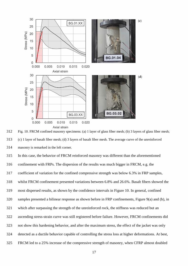
Fig. 10. FRCM confined masonry specimens: (a) 1 layer of glass fiber mesh; (b) 3 layers of glass fiber mesh; 312
(c) 1 layer of basalt fiber mesh; (d) 3 layers of basalt fiber mesh. The average curve of the unreinforced 313
masonry is remarked in the left corner. 314
In this case, the behavior of FRCM reinforced masonry was different than the aforementioned 315
confinement with FRPs. The dispersion of the results was much bigger in FRCM, e.g. the 316
coefficient of variation for the confined compressive strength was below 6.3% in FRP samples, 317
whilst FRCM confinement presented variations between 6.8% and 26.6%. Basalt fibers showed the 318
most dispersed results, as shown by the confidence intervals in Figure 10. In general, confined 319
samples presented a bilinear response as shown before in FRP confinements, Figure 9(a) and (b), in 320
which after surpassing the strength of the unreinforced rock, the stiffness was reduced but an 321
ascending stress-strain curve was still registered before failure. However, FRCM confinements did 322
not show this hardening behavior, and after the maximum stress, the effect of the jacket was only 323
detected as a ductile behavior capable of controlling the stress loss at higher deformations. At best, 324
FRCM led to a 25% increase of the compressive strength of masonry, when CFRP almost doubled 325

18
it. The FRCM with only one layer of glass fiber mesh obtained the same strength level than the bare 326
masonry set. The main difference between mesh types and number of layers was observed in the 327
softening behavior, in which the progressive failure of the reinforcement occurred as fiber meshes 328
broke. Hence, there was not neither an explosive failure nor a clear failure point like those in FRP 329
confined specimens. In order to evaluate the ductility gain, the same criteria explained for FRP 330
confined specimens was used to select failure strain values (20% stress drop after peak stress [15]). 331
These strain values, included in Table 7, the confined samples with better ductility were obtained 332
using basalt fiber meshes. Actually, only the set reinforced with three layers of basalt fibers 333
achieved a deformation level of 1.68% (6 times higher than unreinforced masonry), and similar to 334
FRP confined samples, but with only a 24% strength gain. From the point of view of the failure 335
mode, once again it was completely different to the aforementioned explosive behavior of FRP 336
confinement. As shown in Figure 10, masonry specimens after failure were barely damaged, and the 337
fracture was almost similar to unconfined samples. 338
Table 7. FRCM confined columns: experimental results, average value (coefficient of variation). 339
Set fmc (MPa) fmc / fmo εmc εmc / εmo εmc,t εfu kε GG.01.XX 20.95 (9.06%) 1.01 0.00439 (11.32%) 1.66 0.00059 (29.69%) 0.00273 0.22 GG.03.XX 26.22 (6.84%) 1.26 0.00583 (12.19%) 2.21 0.00054 (26.05%) 0.00273 0.20 BG.01.XX 25.09 (26.58%) 1.21 0.00601 (14.06%) 2.28 0.00196 (21.67%) 0.01771 0.11 BG.03.XX 25.74 (11.49%) 1.24 0.01683 (20.20%) 6.37 0.00418 (14.08%) 0.01771 0.23
340
3.3. Comparative study 341
Before any further discussion, the differences in the dispersion of results should be remarked. As 342
shown in the confidence intervals of Figures 9 and 10, the behavior of FRP confinements was more 343
homogeneous, and FRCM jackets showed higher dispersion of their mechanical response. For a 344
better comparison between each composite, and their efficiency as confinement solution, Figure 11 345
includes the strength and strain ratios between reinforced samples and unreinforced masonry, i.e. 346
fmc/fmo and εmc/εmo respectively. In addition, Figure 11(b) represents the confinement ratios of each 347
system, and Figure 11(c) includes the ratio of the strength gain with respect of the amount of fibers 348
19
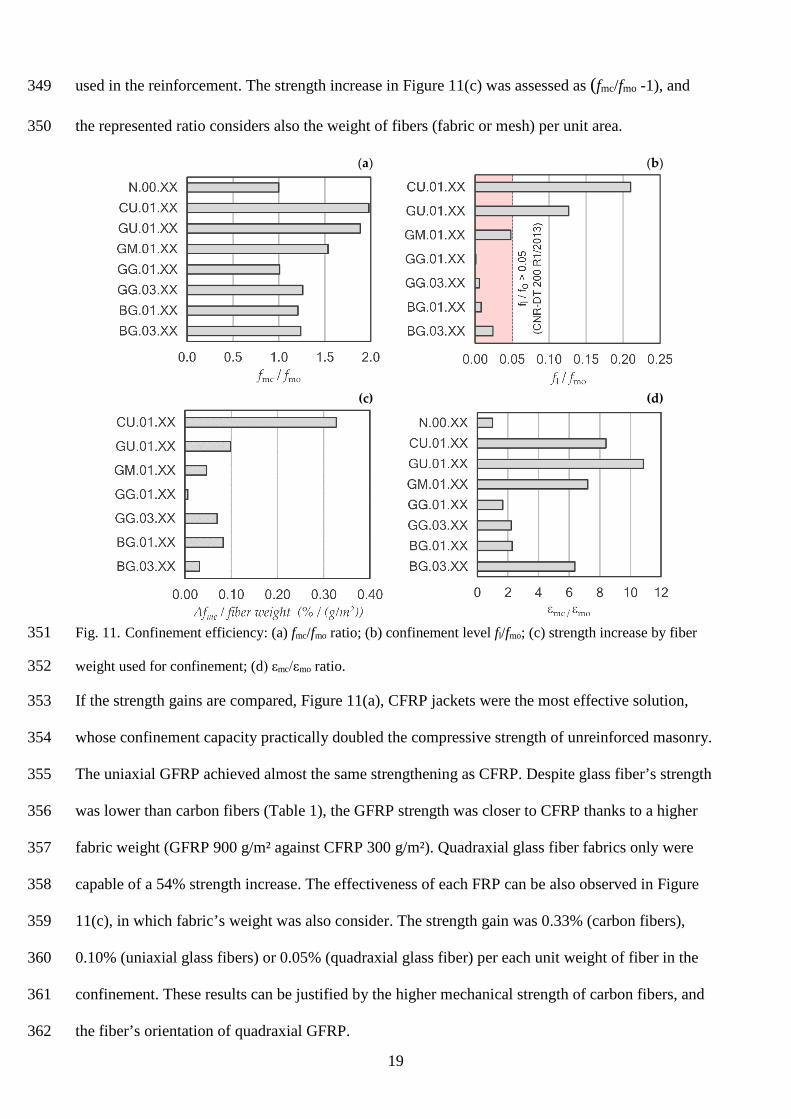
used in the reinforcement. The strength increase in Figure 11(c) was assessed as (fmc/fmo -1), and 349
the represented ratio considers also the weight of fibers (fabric or mesh) per unit area. 350
(a) (b)
(c) (d)
Fig. 11. Confinement efficiency: (a) fmc/fmo ratio; (b) confinement level fl/fmo; (c) strength increase by fiber 351
weight used for confinement; (d) εmc/εmo ratio. 352
If the strength gains are compared, Figure 11(a), CFRP jackets were the most effective solution, 353
whose confinement capacity practically doubled the compressive strength of unreinforced masonry. 354
The uniaxial GFRP achieved almost the same strengthening as CFRP. Despite glass fiber’s strength 355
was lower than carbon fibers (Table 1), the GFRP strength was closer to CFRP thanks to a higher 356
fabric weight (GFRP 900 g/m² against CFRP 300 g/m²). Quadraxial glass fiber fabrics only were 357
capable of a 54% strength increase. The effectiveness of each FRP can be also observed in Figure 358
11(c), in which fabric’s weight was also consider. The strength gain was 0.33% (carbon fibers), 359
0.10% (uniaxial glass fibers) or 0.05% (quadraxial glass fiber) per each unit weight of fiber in the 360
confinement. These results can be justified by the higher mechanical strength of carbon fibers, and 361
the fiber’s orientation of quadraxial GFRP. 362

20
Nevertheless, FRCM confinements could not achieved these results, and their best mechanical 363
performance (only a 26% improvement) was obtained with three mesh layers. The low mechanical 364
performance can be also explain based on the confinement ratios included in Figure 11(b). Only the 365
confinements made in uniaxial CFRP or GFRP surpass the minimum level of confinement 366
suggested in CNR-DT 200 R1/2013 (fl/fmo>5%). Hence, based on the actual confinement levels of 367
each material FRCM shouldn’t present an increasing stress-strain response [13]. Therefore, the 368
FRCM types tested in this work did not seem as an appropriate solution for the confinement of 369
masonry elements under compression, if a strength increase was expected. However, in other 370
references, a better mechanical performance of these materials was achieved with fibers and 371
mortars with higher mechanical properties, for example, up to three layers of carbon fibers (with 372
strength of 3350 MPa and elastic modulus of 225 GPa) [15], or PBO fibers (strength 5800 MPa, 373
modulus 270 GPa) [18]. In both cases the mechanical properties of the fibers were higher than 374
those used in this research, which can explain the better strengthening result. Nonetheless, this type 375
of FRCM may be a suitable solution for other loading conditions like lateral in-plane loads induced 376
by seismic actions [48]. 377
From the point of view of the increase of the ultimate strain and ductility gain, Figure 11(d), once 378
again unidirectional FRP presented the best results. GFRP jackets increase more than 10 times the 379
ultimate strain of masonry. Confinements with quadraxial fabrics achieved a 7 times strain 380
increase, despite most of the fiber’s weight was wasted because their orientation. Finally, according 381
to the current experimental tests the use of FRCM as confinement solution did not seem an 382
appropriate solution. Only several layers of basalt fiber FRCM may have been shown a slight 383
strength increase but with more than six times the ultimate strain (determined for a 20% stress drop 384
after peak stress). Hence, this type of FRCM may be selected to increase the ductility of masonry 385
columns. 386
3.4. Comparison with design guidelines 387

21
In this last section, the experimental results presented above have been compared with the values 388
obtained following the procedure in two Italian guidelines: CNR-DT 200 R1/2013 [34] for FRP 389
strengthening of structures and CNR-DT 215/2018 [35], recently released with specific 390
considerations for FRCM reinforcements. Other available design codes consider confinement 391
models for axially loaded elements [36-39]. In general, the constitutive laws in these codes only 392
include parameters to evaluate concrete structures. Hence, the Italian guidelines were selected 393
because they are currently the only two that considered specific values for masonry or stone 394
structures. 395
These codes assume a confinement model based on Lam & Teng [13], in which the compressive 396
strength of the confined element (fmc) is related to the unreinforced masonry strength (fmo) 397
according to Eq. (1). 398
fmc = fmo �1 + k´�fl,eff
fmo�
α1
� (1)
where fl,eff is the effective confinement stress; α1 is a coefficient that can be assumed equal to 0.5, 399
or determined based on experimental tests; k’ is a non-dimensional coefficient that can be 400
determined using Eq. (2). 401
k' = α2 �gm
1000�
α3 (2)
where gm is the unreinforced masonry mass-density (kg/m³) and coefficients α2 and α3 may be 402
assumed equal to 1.0, unless additional experimental evidence says otherwise. In addition, the 403
effective confinement stress (fl,eff) depends on the shape of the cross section of the confined 404
element, and the material and configuration of the jacket. Both effects are considered in the 405
efficiency factor (keff), which will be equal to 1.0 in the conditions of the samples in this work 406
(cylindrical samples and continuous jacket, FRP or FRCM, along the total length of each sample). 407
Hence, in the calculations below, the confinement stress fl matches with the effective confinement 408
stress fl,eff. 409
fl,eff = keff · fl ≈ fl (3)

22
The lateral confinement stress can be obtained from the equilibrium in a cross section of the 410
confined element, Eq. (4), where nf is the number of layers in the reinforcement; tf the thickness of 411
the FRP, or the equivalent thickness of fibers in FRCM reinforcements (without considering the 412
cement matrix); Ef is the elastic modulus of the FRP or the fiber mesh in FRCM; εf,red is the 413
reduced strain at failure of the jacket; and D is the diameter of the masonry element to be confined. 414
fl = 2 nf tf Ef εf,red
D (4)
The reduced strain at failure of the jacket will be obtained differently depending on the type of 415
reinforcement. For example, for FRP confinement the minimum value of two conditions shall be 416
consider, Eq. (5). The first factor includes durability issues: the coefficient ηa depends on the FRP 417
type and the exposure level, for non-exposed elements this factor is 0.95 for CFRP or 0.75 for 418
GFRP; εfu is the ultimate strain of the FRP in direct tensile tests; finally, γf is an additional safety 419
factor equal to 1.10 for confinement reinforcement. 420
εf,red = min �ηaεfu
γf; 0.004� (5)
The second limit, 0.004, is defined to avoid an excessive damage of the masonry core, which could 421
compromise the structural stability, especially under out-of-plane loads. This second condition is 422
also applicable to FRCM reinforcements, Eq. (6), but in that case, the first limit is slightly 423
modified: ηa only depends on the exposure (0.90 in this case) but does not depend on the fiber type 424
of the FRCM. The safety factor γm is 1.50 in ULS, and there is and additional non-dimensional 425
factor that considers the matrix characteristics and can be obtained using Eq. (7). 426
εf,red = min �kmat ηaεfu
γm; 0.004� (6)
kmat = α4 �4 tmat
D·
fc,mat
fmo�
2
≤ 1 (7)
where α4 is assumed 1.81 when additional experimental data are unavailable; tmat is the total 427
thickness of the FRCM jacket; and fc,mat is the characteristic compressive strength of the mortar 428
matrix. 429
23
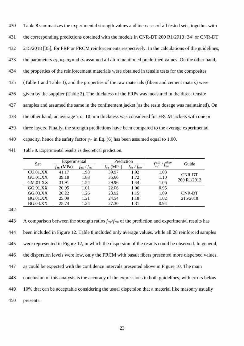
Table 8 summarizes the experimental strength values and increases of all tested sets, together with 430
the corresponding predictions obtained with the models in CNR-DT 200 R1/2013 [34] or CNR-DT 431
215/2018 [35], for FRP or FRCM reinforcements respectively. In the calculations of the guidelines, 432
the parameters α1, α2, α3 and α4 assumed all aforementioned predefined values. On the other hand, 433
the properties of the reinforcement materials were obtained in tensile tests for the composites 434
(Table 1 and Table 3), and the properties of the raw materials (fibers and cement matrix) were 435
given by the supplier (Table 2). The thickness of the FRPs was measured in the direct tensile 436
samples and assumed the same in the confinement jacket (as the resin dosage was maintained). On 437
the other hand, an average 7 or 10 mm thickness was considered for FRCM jackets with one or 438
three layers. Finally, the strength predictions have been compared to the average experimental 439
capacity, hence the safety factor γm in Eq. (6) has been assumed equal to 1.00. 440
Table 8. Experimental results vs theoretical prediction. 441
Set Experimental Prediction fmc exp / fmc
theo Guide fmc (MPa) fmc / fmo fmc (MPa) fmc / fmo CU.01.XX 41.17 1.98 39.97 1.92 1.03 CNR-DT
200 R1/2013 GU.01.XX 39.18 1.88 35.66 1.72 1.10 GM.01.XX 31.91 1.54 29.96 1.44 1.06 GG.01.XX 20.95 1.01 22.06 1.06 0.95
CNR-DT 215/2018
GG.03.XX 26.22 1.26 23.92 1.15 1.09 BG.01.XX 25.09 1.21 24.54 1.18 1.02 BG.03.XX 25.74 1.24 27.30 1.31 0.94
442
A comparison between the strength ratios fmc/fmo of the prediction and experimental results has 443
been included in Figure 12. Table 8 included only average values, while all 28 reinforced samples 444
were represented in Figure 12, in which the dispersion of the results could be observed. In general, 445
the dispersion levels were low, only the FRCM with basalt fibers presented more dispersed values, 446
as could be expected with the confidence intervals presented above in Figure 10. The main 447
conclusion of this analysis is the accuracy of the expressions in both guidelines, with errors below 448
10% that can be acceptable considering the usual dispersion that a material like masonry usually 449
presents. 450

24
451
Fig. 12. CNR-DT 200 R1/2013 (FRP) or CNR-DT 215/2018 (FRCM) strength ratios (fmc/fmo) vs 452
experimental results for confined masonry samples. 453
4. CONCLUSIONS 454
Masonry samples were prepared using calcarenite pieces from geotechnical surveys and lime 455
mortar. Afterwards, different materials, FRP and FRCM each one with two types of fibers, were 456
used as confinement to test experimentally their reinforcement efficiency. After the tests and 457
different analyses, the following conclusions can be drawn: 458
1. Masonry samples confined with unidirectional GFRP and CFRP almost doubled the 459
compressive strength of unreinforced masonry. These specimens also showed higher ductility with 460
ultimate strain values up to ten times bigger than unreinforced samples. 461
2. Quadraxial GFRP presented a limited capacity as confinement solution because fiber 462
orientation. However, the failure mode was more ductile, compared to the explosive brittle failure 463
showed by the other GFRP and CFRP specimens. 464
3. FRCM jackets presented limited confinement ratio, hence the strength gain was up to 26% of the 465
strength of unreinforced masonry. On the other hand, the stress-strain curves of the confined 466
masonry with FRCM showed a softening behavior (decreasing curves), in which basalt fiber 467
meshes seemed to generate more ductile failures. Higher fiber dosages or fibers with higher 468
strength would be necessary to obtain increasing strain-stress curves with better strength gains. 469
25
4. These experimental results were compared with the confinement model predictions of two 470
Italian design guidelines, CNR-DT 200 R1/2013 for FRP and CNR-DT 215/2018 for FRCM. 471
Among all the available codes, these two were selected as the only ones that considered specific 472
values for masonry structures, which led to particularly accurate results, with errors below 10% 473
between the predicted and experimental values. 474
ACKNOWLEDGMENTS 475
The authors would like to acknowledge Mapei Spain S.A. for the materials supplied in this research. This 476
research and the APC were funded by Spanish Ministry of Economy and Competitiveness, grant number 477
BIA2015-69952-R and Spanish Ministry of Science, Innovation and Universities, grant number RTI2018-478
101148-B-I00. 479
DATA AVAILABILITY 480
Data may be available upon request to the corresponding author. 481
REFERENCES 482
1. S. Ivorra, R. Irles, L. Estevan, J.M. Adam, F.J. Pallarés, B. Ferrer, Drucker-Prager yield criterion 483 application to study the behavior of CFRP confined concrete under compression, 37th IAHS World 484 Congress on Housing, Santander, Spain (2010). 485
2. D. Bru, S. Ivorra, F.J. Baeza, Seismic behavior of a masonry chimney retrofitted with composite 486 materials: A preliminary approach, Int. J. Saf. Secur. Eng. 7 (2017) 486–497. 487
3. L.C. Hollaway, A review of the present and future utilisation of FRP composites in the civil 488 infrastructure with reference to their important in-service properties, Constr. Build. Mater. 24 (2010) 489 2419–2445. 490
4. S.A. Babatunde, Review of strengthening techniques for masonry using fiber reinforced polymers, 491 Compos. Struct. 161 (2017) 246–255. 492
5. L.A.S. Kouris, T.C. Triantafillou, State-of-the-art on strengthening of masonry structures with textile 493 reinforced mortar (TRM), Constr. Build. Mater. 188 (2018) 1221–1233. 494
6. T. Krevaikas D., Experimental study on carbon fiber textile reinforced mortar system as a means for 495 confinement of masonry columns, Constr. Build. Mater. 208 (2019) 723–733. 496
7. A. Nanni, N.M. Bradford, FRP jacketed concrete under uniaxial compression, Constr. Build. Mater. 9 497 (1995) 115–124. 498
8. A. Mirmiran, M. Shahawy, Behavior of concrete columns confined by fiber composites, J. Struct. Eng. 499 (1997) 583–590. 500
9. H.A. Toutanji, Stress-strain characteristics of concrete columns externally confined with advance fiber 501 composite sheets, ACI Mater. J. 96 (1999) 397–404. 502
10. S. Pessiki, K.A. Harries, J.T. Kestner, R. Sause, J.M. Ricles, Axial behavior of reinforced concrete 503 columns confined with FRP jackets, J. Compos. Constr. 5 (2001) 237–245. 504
11. L.-M. Wang, Y.-F Wu, Effect of corner radius on the performance of CFRP-confined square concrete 505 columns: Test, Eng. Struct. 30 (2008) 493–505. 506
12. M.R. Spoelstra, G. Monti, FRP-confined concrete model, J. Compos. Constr. 3 (1999) 143–150. 507

26
13. L. Lam, J.G. Teng, Design-oriented stress–strain model for FRP-confined concrete, Constr. Build. 508 Mater. 17 (2003) 471–489. 509
14. T. Ozbakkaloglu, J.C. Lim, T. Vincent, FRP-confined concrete in circular sections: Review and 510 assessment of stress–strain models, Eng. Struct. 49 (2013) 1068–1088. 511
15. T.C. Triantafillou, C.G. Papanicolaou, P. Zissimopoulos, T. Laourdekis, Concrete confinement with 512 textile-reinforced mortar jackets, ACI Struct. J. 103 (2006) 28–37. 513
16. M. Di Ludovico, A. Prota, G. Manfredi, Structural upgrade using basalt fibers for concrete 514 confinement, J. Compos. Constr. 14 (2010) 541–552. 515
17. F.J. De Caso y Basalo, F. Matta, A. Nanni, Fiber reinforced cement-based composite system for 516 concrete confinement, Constr. Build. Mater. 32 (2012) 55–65. 517
18. P. Colajanni, F. De Domenico, A. Recupero, N. Spinella, Concrete columns confined with fibre 518 reinforced cementitious mortars: Experimentation and modelling, Constr. Build. Mater. 52 (2014) 375–519 384. 520
19. A. Cascardi, F. Longo, F. Micelli, M.A. Aiello, Compressive strength of confined column with Fiber 521 Reinforced Mortar (FRM): New design-oriented-models, Constr. Build. Mater. 156 (2017) 387–401. 522
20. M.A. Aiello, F. Micelli, L. Valente, Structural upgrading of masonry columns by using composite 523 reinforcements, J. Compos. Constr. 11 (2007) 650–658. 524
21. M.A. Aiello, F. Micelli, L. Valente, FRP confinement of square masonry columns, J. Compos. Constr. 525 13 (2009) 148–158. 526
22. C. Faella, E. Martinelli, S. Paciello, G. Camorani, M.A. Aiello, F. Micelli, E. Nigro, Masonry columns 527 confined by composite materials: Experimental investigation, Compos. Part B Eng. 42 (2011) 692–704. 528
23. F. Micelli, R. Angiuli, P. Corvaglia, M.A. Aiello, Passive and SMA-activated confinement of circular 529 masonry columns with basalt and glass fibers composites, Compos. Part B Eng. 67 (2014) 348–362. 530
24. J. Witzany, R. Zigler, Failure mechanism of compressed reinforced and non-reinforced stone columns, 531 Mater. Struct. 48 (2015) 1603–1613. 532
25. J. Witzany, R. Zigler, Stress state analysis and failure mechanisms of masonry columns reinforced with 533 FRP under concentric compressive load, Polym. 8 (2016) 176. 534
26. L. Estevan, F.J. Baeza, V. Brotons, S. Ivorra, FRP confinement of stone specimens after high 535 temperature exposure: Experimental tests, REHABEND, Burgos, Spain (2016) 1457-1464. 536
27. L. Estevan, F.J. Baeza, S. Ivorra, FRP confinement of fire-damaged calcarenite samples, CMMoST 537 2017, Madrid, Spain (2017) 317–327. 538
28. P.E. Mezrea, I.A. Yilmaz, M. Ispir, E. Binbir, I.E. Bal, A. Ilki, External jacketing of unreinforced 539 historical masonry piers with open-grid basalt-reinforced mortar, J. Compos. Constr. 21 (2017) 540 04016110. 541
29. A. Cascardi, F. Micelli, M.A. Aiello, FRCM-confined masonry columns: experimental investigation on 542 the effect of the inorganic matrix properties, Constr. Build. Mater. 186 (2018) 811–825. 543
30. T. Krevaikas D., Experimental study on carbon fiber textile reinforced mortar system as a means for 544 confinement of masonry columns, Constr. Build. Mater. 208 (2019) 723–733. 545
31. F.S. Murgo, C. Mazzotti, Masonry columns strengthened with FRCM system: Numerical and 546 experimental evaluation, Constr. Build. Mater. 202 (2019) 208–222. 547
32. G.P. Lignola, R. Angiuli, A. Prota, M.A. Aiello, FRP confinement of masonry: analytical modeling, 548 Mater. Struct. Constr. 47 (2014) 2101–2115. 549
33. G. Minafò, J. D’Anna, C. Cucchiara, A. Monaco, L. La Mendola, Analytical stress-strain law of FRP 550 confined masonry in compression: Literature review and design provisions, Compos. Part B Eng. 115 551 (2017) 160–169. 552
34. CNR-DT 200 R1/2013, Guide for the design and construction of externally bonded FRP systems for 553 strengthening existing structures, National Research Council, Roma, Italy (2014). 554

27
35. CNR-DT 215/2018, Istruzioni per la progettazione, l’esecuzione ed il controllo di interventi di 555 consolidamento statico mediante l’utilizzo di compositi fibrorinforzati a matrice inorganica, National 556 Research Council, Roma, Italy (2019). 557
36. ACI 440.2R-17, Guide for the design and construction of externally bonded FRP systems for 558 strengthening concrete structures, American Concrete Institute, ACI Committee 440 (2017). 559
37. ACI 549.4R-13, Guide to design and construction of externally bonded fabric-reinforced cementitious 560 matrix (FRCM) systems for repair and strengthening concrete and masonry structures, American 561 Concrete Institute, ACI Committee 549 (2013). 562
38. TR-55, The Concrete Society Technical Report 55: Design guidance for strengthening concrete 563 structures using fibre composite materials, 3rd Ed., The Concrete Society (2013). 564
39. FIB Bulletin Nº 14, Externally bonded FRP reinforcement for RC structures, Fédération Internationale 565 du Béton (2001). 566
40. ASTM D7012-14e1, Standard test methods for compressive strength and elastic moduli of intact rock 567 core specimens under varying states of stress and temperatures, ASTM International, West 568 Conshohocken, PA (2014). 569
41. V. Brotóns, R. Tomás, S. Ivorra, J.C. Alarcón, Temperature influence on the physical and mechanical 570 properties of a porous rock: San Julian’s calcarenite, Eng. Geol. 167 (2013) 117–127. 571
42. V. Brotons, R. Tomás, S. Ivorra, A. Grediaga, Relationship between static and dynamic elastic modulus 572 of calcarenite heated at different temperatures: The San Julián’s stone, Bull. Eng. Geol. Environ. 73 573 (2014) 791–799. 574
43. ASTM D7565 / D7565M-10 (2017), Standard test method for determining tensile properties of fiber 575 reinforced polymer matrix composites used for strengthening of civil structures, ASTM International, 576 West Conshohocken, PA (2017). 577
44. AC434, Acceptance criteria for masonry and concrete strengthening using fabric-reinforced 578 cementitious matrix (FRCM) composite systems, ICC Evaluation Service (2017). 579
45. M. Leone, M.A. Aiello, A. Balsamo, F.G. Carozzi, F. Ceroni, M. Corradi, M. Gams, E. Garbin, N. 580 Gattesco, P. Krajewski, C. Mazzotti, D. Oliveira, C. Papanicolaou, G. Ranocchiai, F. Roscini, D. 581 Saenger, Glass fabric reinforced cementitious matrix: Tensile properties and bond performance on 582 masonry substrate, Compos. Part B Eng. 127 (2017) 196-214. 583
46. UNE 66040:2003, Statistical interpretation of test results. Estimation of the mean. Confidence interval, 584 AENOR, Spanish Association for Standardisation (2004). 585
47. L. Estevan, F.J. Baeza, F.B. Varona, S. Ivorra, FRP retrofitting of calcarenite samples after high 586 temperature exposure, Compos. Struct. (2019) (under review). 587
48. S. Ivorra, D. Bru, A. Galvañ, S. Silvestri, C. Apera, D. Foti, TRM reinforcement of masonry specimens 588 for seismic areas, Int. J. Saf. Secur. Eng. 7 (2017) 436–474. 589
590

28
List of Tables: 591
Table 1. Main properties of FRP raw materials and composite specimens. 592
Table 2. FRCM mesh and mortar properties, values provided by supplier. 593
Table 3. FRCM properties, experimental values from uniaxial tensile tests 1. 594
Table 4. Specimen’s identification and reinforcement’s characteristics. 595
Table 5. Unconfined columns: experimental results, average value (coefficient of variation). 596
Table 6. FRP confined masonry: experimental results, average values (coefficient of variation). 597
Table 7. FRCM confined columns: experimental results, average value (coefficient of variation). 598
Table 8. Experimental results vs theoretical prediction. 599
600 List of Figures: 601
Fig. 1. Stone masonry preparation: (a) lime mortar and vertical alignment; (b) 32 masonry 602
specimens before reinforcement. 603
Fig. 2. Fabrics for the FRP reinforcements: (a) unidirectional CFRP; (b) unidirectional GFRP; (c) 604
quadraxial GFRP. Meshes for FRCM jackets: (d) glass fiber mesh; (e) basalt fiber mesh. 605
Fig. 3. Stress vs strain results measured in uniaxial tension tests according to ASTM 606
D7565/D7565M-10 (2017) for different FRP types: uniaxial CFRP (CU), uniaxial GFRP (GU), and 607
multiaxial GFRP (GM). 608
Fig. 4. Direct tensile test of FRCM specimens: (a) experimental setup; (b) crack pattern of a basalt 609
fiber sample; (c) stress vs strain idealized behavior as shown in AC434. 610
Fig. 5. Tensile test results, stress vs strain of FRCM specimens with (a) glass fiber mesh (GG) or 611
(b) basalt fiber mesh (BG). 612
Fig. 6. Reinforcement of masonry samples with composites: (a) FRP confinement; (b) mortar and 613
fiber mesh of the FRCM confinement, and (c) end faces for a proper load application. 614
Fig. 7. Test procedure: (a) general view of the 32 tested samples with different reinforcements; (b) 615
longitudinal compression test setup. 616

29
Fig. 8. Unreinforced masonry results: longitudinal stress-strain curve (average ± 95% confidence 617
interval) and failure mode. 618
Fig. 9. FRP confined masonry specimens: (a) unidirectional CFRP; (b) unidirectional GFRP; (c) 619
quadraxial GFRP. The average curve of the unreinforced masonry is remarked in the left corner. 620
Fig. 10. FRCM confined masonry specimens: (a) 1 layer of glass fiber mesh; (b) 3 layers of glass 621
fiber mesh; (c) 1 layer of basalt fiber mesh; (d) 3 layers of basalt fiber mesh. The average curve of 622
the unreinforced masonry is remarked in the left corner. 623
Fig. 11. Confinement efficiency: (a) fmc/fmo ratio; (b) confinement level fl/fmo; (c) strength increase 624
by fiber weight used for confinement; (d) εmc/εmo ratio. 625
Fig. 12. CNR-DT 200 R1/2013 (FRP) or CNR-DT 215/2018 (FRCM) strength ratios (fmc/fmo) vs 626
experimental results for confined masonry samples. 627