Embed Size (px)
Citation preview
1
Starting System Principles
Uses battery power

2
AUTOMOTIVE STARTING SYSTEMS
Starter Circuit Electric DC Motor
(starter motor) Solenoid or Relay Gear Drive Switches
& Controls Wiring Testing Removing Starter

3
STARTING SYSTEM PARTS Battery Ignition switch Solenoid Starting motor

4
STARTER CIRCUIT
Battery / Cables Magnetic
Switches Solenoids
• Pull in Windings
• Hold in Windings
• Pinion Gear
Starter Relay
5
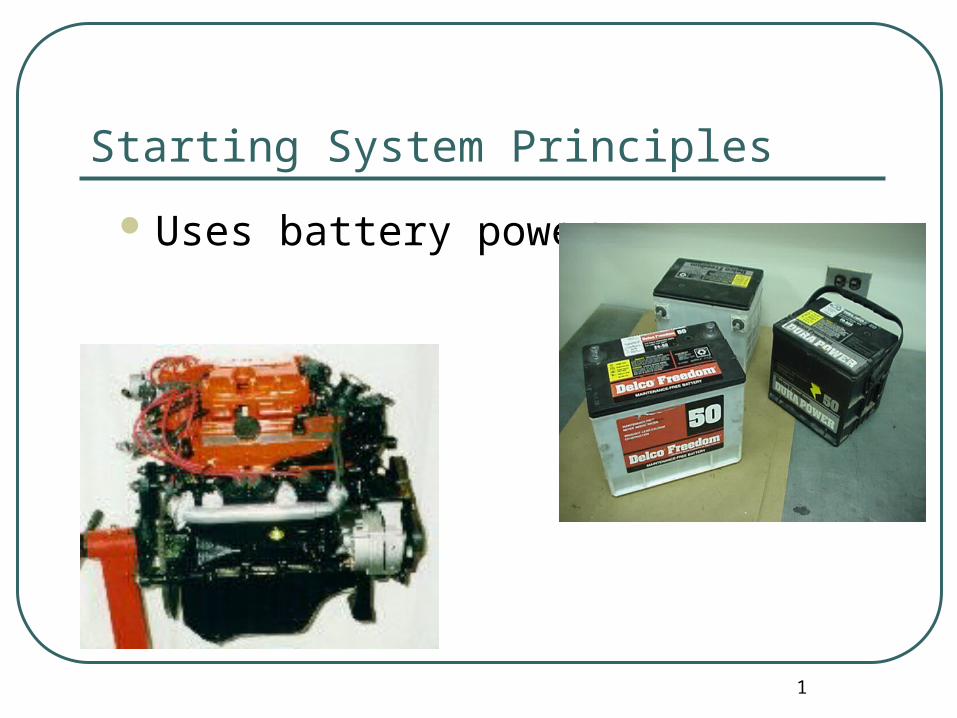
Starter Circuit Simplified

6
Starter Solenoid Functions * Close battery to
starter connection * Push pinion gear
into fly wheel * Bypass the
resistance wire of ignition circuit
Move the starter drive into mesh w. flywheel
Complete the starter circuit

7
Starting System Action
Energizes solenoid
Current flows to Solenoid
Turn key
Connects current to starter motor
Motor turns flywheel Turns crankshaft
Moves pistons up and down
1
Turns starter
Moves pinion forward

8
Starter System Action cont.

9
Starter Motor Fundamentals
Converts Electrical Energy From Battery Into
Mechanical Energy
TORQUE

10
DC MOTOR Basic Components
Housings and End Frames
Pole Shoes (magnets)
Field Coils • (windings) x 3 or 4
Armature (spins) Commutator Brushes x4

11
MOTOR OPERATION
Magnetic Field Action• made of invisible lines of force (flux)
• flow through wire
• flow around wire
• alike charges repel
• Dissimilar Charges attract(spinning action)
• Used to produce motion

12
DRIVE MECHANISM
Positive engagement• Movable pole shoe
Solenoid-actuated• Gear reduction drive

13
Simple Electric Motors
Wire loop field Set up between
poles POLE SHOES
14
Changing Electricity Into Motion
Place windings inside pole shoes Current through loop Fields act upon each other

15
Commutators and Brushes
Used to keep motor spinning• by controlling current passing through windings
commutator Sliding electrical connection
• Between motor windings and brushes
• Many segments
• Insulated from each other Motor brushes
• Ride on comutator
• (slide on commutator)
• Carry current to spinning windings

16
Commutators and Brushes
Increasing Motor Power• several windings
• wires
Commutator • several segments
• constant smooth motion

17
Armatures
Must produce HIGH torque• turning power
• relatively high speed

18
Starter Armature parts shaft supports windings/armature inside housing Core (holds windings in place)
• made of iron (Fe) increases magnetic field strength Commutator
• for brush contact• Windings
• wires

19
Field Windings stationary insulated wires wrapped in circular shape creates strong magnetic field around motor armature 5-10 x stronger than perminate magnets field in pole shoes acts against field in
armature = motor spins
20
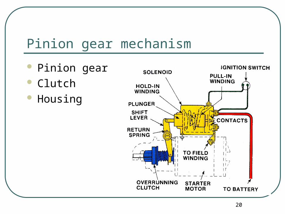
Pinion gear mechanism
Pinion gear Clutch Housing

21
Starter Pinion Gears
Small gear on armature shaft Engages to flywheel Meshes
Fly Wheel Turns Engine

22
Overrunning Clutch
Locks pinion gear in one direction Releases it in other direction Spiral grooves in shaft Allows starter motor to crank the
engine Protects the starter from damage if the
starter is cranked while the engine is running

23
Starter Solenoid
High current relay Makes electrical connection between
• Battery & starter
Electromagnetic switch Handle VERY HIGH currents

24
Starter Solenoid Operation
Key turned (start position) Current flows through solenoids windings Produces magnetic field Pulls plunger and disc into coil windings Causes disc to touch both high current
terminals Completes circuit battery to starter Current of 150-200A
25
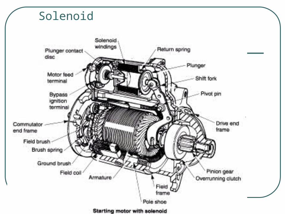
Solenoid

26
Key Released
Current disconnected Magnetic field collapses Plunger slides back Starter shuts off

27
Increasing Motor Power
Several windings Wires Comutator Several segments Constant smooth motion

28
RELATED MOTOR TERMINOLOGY
Left hand or right hand rule Torque Current Draw

29
STARTER DRIVE END Connects the armature
shaft to the flywheel. Usually shifted out by the
solenoid. Contains an over- running
clutch for protection. Pinion gear meshes with
the flywheel ring gear. Returned to the rest
position by a spring.

30
SOLENOID
A linear motor Contains two windings a
pull-in and a hold-in winding.
Pushes the starter drive(pinion) into mesh with the flywheel ring gear.
Completes the circuit to the motor.

31
CONTROL CIRCUIT
Starting Safety Switch
Neutral Safety Switch• On
transmission
• On Clutch

32
Starting Motor Types
classified by: kind of pinion gear engagement moveable pole shoe solenoid Movable pole shoe uses a yoke “Y” moves pinion gear hinged shoe on starter
frame yoke links pole shoe & pinion gear

33
Internal Motor Circuits
3 common internal connections
Series• maximum torque
• torque decreases throughout cranking
Shunt• Less torque
• More constant torque
Compound• series/shunt
• good toque
• constant speed
34
Neutral Safety Switch
prevents cranking unless in P or N Ford - brake on LOCATION Connected in series with the ignition
switch and solenoid• shifter or transmission
35
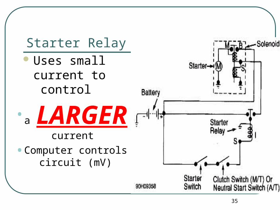
Starter Relay Uses small current to
control • a
LARGER current
• Computer controls circuit (mV)
36
Starter Types
Starter Mounted Solenoids plunger moves shift lever
• GM/Chrysler
Permanent Magnet Starter Use high strength permanent magnets NOT CONVENTIONAL WINDINGS = MORE torque

37
Starter Motor Torque
Must turn engine all components Can Not Stall Reduction starter
• extra set of gears
• increase rotating force
• higher speeds
• higher torque
• more constant cranking speeds

38
STARTER TESTING
Preliminary Tests Safety Precautions Troubleshooting
Procedures Battery Load Test Cranking Voltage Test Cranking Current Test Insulated Resistance
Test
Starter Relay By-pass Test
Ground Circuit Resistance Test
Voltage Drop to Control Unit
Test Components

39
Problems
Starter relay or solenoid clicks• low battery charge
Whining• Plunger stuck
Grinding• Poor engagement
Slow turn• Low battery
• Internal short

40
Battery Load Test
VAT 40 All Accessories on ½ CCA

41
Test
Cranking Voltage • DVOM across battery
Cranking Current Test• Inductive Pick Up
• Current draw
• 150-200 AMPS
Voltage Drop Test

42
Tests Test Relay Ground Circuit
Resistance Test Starter Relay Bypass
Test Ground test Bench test

43
Starter Motor Disassembly