Embed Size (px)
Citation preview
AD-ft171 733 A SORTING SYSTEM USING VERY LOWl RESOLUTION OPTICAL 1SENSOR ARRAY IN ROBOT FINGERTIPS(U) CARNEGIE-MELLON
UNVPTSUG P OOISISTRGYN TA7UNCLASSIFIED MARY 96 CHU-RI-TR-B6-L F/G 03/8 N
ENEM~hEhh

1111 11.012.
11111L.5 1.
MICROCOPY RESOLUTION TEST CHART
NATIONAL. BUJFAIJ OF S1ANDARDI Ill A 1
* %* .
.\ F
. ~ **. - , *A* ~ ...e
* - r"'~-* r~'~ rr--'~. - '~'yy~ '~ .r r.v ~WA.
- - -~ * ~') '4V V'~l'~ ~' ~ C
4 ''it. I ;.,~~l4tCO At ~ . :1.
~.s-A.N.
*4- ~- .
kit, . .
. . . . A .~
-. 5t.i~
LiIf-, I*~
-. t~
a , .. ~-( -
-. -, t, I
~ ~ ~
.44
A Sorting Systemn Using Very Low Resolution MOptical Sensor A rray in RoboZ jji'Jrtps
R. 0. Yang and M. W. Siegel
CMU-RI-TRI-86-1O .MNN
86 9 10 067
Shenyang Institute of AutomationChinese Academly of Sciences
Shenyangj, China -
Intelligent Sensors LaboratoryThe Robotics Institute
Carnegie-Mellon UniversityPittsburgh, Pennsylvania 15213
May 1986
Copyright @ 1986 Carnegie-Mellon Univerzoity
SE~P1
E"i 8emawt hbu be.. sppoutog P~b!!4 Mo~law wd mod" to
1~~1 &trik~~ W i-WziS& 'd
.Unclassified .eSE9CURITIF CI.ASSIVICATIO4, or -- IS P&SE -1%t Date READ1'5RUC1O
REPORT DOCUMEN0TATION PAGE URE CIm@P RUTIGqS
aEOR otarcon R muI. GOVI ACCESSION NO' 3. RECIPIENT'S CATAI.§Gr NubioLm
4. TTYPE ofE StuMA & Ut**JOV
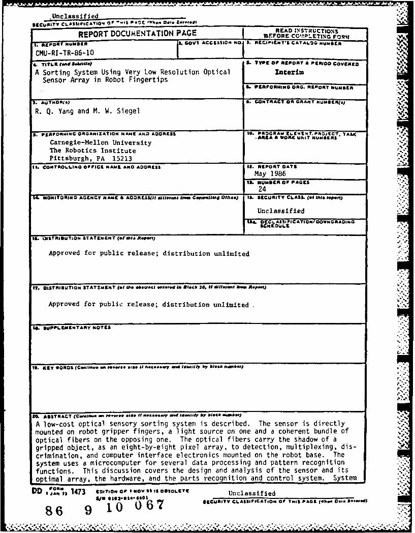
A Sorting System Using Very Low Resolution Optical IsktarimSensor Array in Robot FingertipsN
a. PERFORMING ORo. REPORT HuNSERl
7. AUTWOR(0) S. CONTRACT OilGRANT NUNDILR(eJ
R. Q. Yang and M. W. Siegel
5. PERFORMING ORGANIZATION NAME AND ADDRESS 10. PaROGAMd EL9%i9.T.PRojEC?* TAS4.^89A & WORK UtiT NU84BERS
Carnegie-Mellon UniversityThe Robotics InstitutePittsburgh, PA 15213 _______________
It. C004TROLLING OF VICE N AME AND ADDRESS 12. REPORT OATS
May 198613. HU0N691ROF PAGES
24T4 _ MONITORING AGENCY MNMC AODRESS(If different from CINPwVOIMA 011190) IS. SECURITY C6ASS. (of Wis* repeal)
Unclassified
r .. OE LASSI ICATIO N/ioow NGr, ADi NOC
14. WsTAIDUTION STATEMENT cershi. iteport)
Approved for public release; distribution unlimited
I7. DISIROIBUTION STAT~MEMT (of &b. "*tract am Is Stbck 20. U different bAr RePort)
Approved for public release; distribution unlimited
I&. SUMPEMENTARY NOTES
1S. KEY WORDS (Conszinve an raw"@*. else If foceay aind Identify I,. block "Inab.
20. ASTRACT (C&nw*flmb m to od*e 1 necary and mE*Idiy by block Amber)
A low-cost optical sensory sorting system is described. The sensor is directlymounted on robot gripper fingers, a light source on one and a coherent bundle ofoptical fibers on the opposing one. The optical fibers carry the shadow of agripped object, as an eight-by-eight pixel array, to detection, multiplexing, dis-zocrimination, and computer interface electronics mounted on the robot base. Thesystem uses a microcomputer for several data processing and pattern recognitionfunctions. This discussion covers the design and analysis of the sensor and itsoptimal array, the hardware, and the parts recognition and control system. System
IDD ~, 1473 EDITIONO 00S1WovSSIS ODSOLCTt UnclassifiedS.41 saga2514 4501 SCURITY CLASSIFICATIOPS OF TNIS PAGE Cohen D800B0ee.)
86 9 10 O~

(20. cont.)
performance in a demonstration task requiring the acquisition, identification,
and sorting of a variety of electronic and mechanical parts is described.
Di\ 0t
A~li11itYCodes
- ;~af1. d/ or
DISt Speci-Al
" -T 1 7 . T;.-7 7 7- 7-
..
Table of Contents1. Introduction 22. Design of the Smart Fingers 2
2.1. Light Source 32.2. Receiver 32.3. Design and Analysis of the Array Geometry 3
2.3.1. Pixel Layout 32.3.2. Critical Detectable Object (CDO) 32.3.3. Minimum Detectable Object (MDO) 4
3. Hardware 44. Object Recognition 5
4.1. Segmentation of the Data 74.2. Feature Extraction and Matching 7
5. Control System 85.1. Summary of TeachMover Arm Capabilities 85.2. Scanning a Composite Image 95.3. Motion Control 11
6. Conclusion 117. References 12
.'4
* *%* 'V ~ .. * .*. .. _.
17I
List of FiguresFigure 2-1 : Optical illumination and detection arrays 2Figure 2-2: Two geometries for circular Sensory cell arrays 4Figu re 2-3: Worst cases for object detection 5Figure 2-4: Minimum detectable objects for "Type A" and "Type B" arrays 6Figure 2-5: Critical features for distinguishing between a disc and a square, and a disc 6
and a hexagonFigure 3-1: Sorting system block diagram 7Figure 3-2: Hardware compensation via load resistor array 7Figure 4-1: Flowchart for object recognition 9Figure 4-2: Trial results (enclosed background check not printed out) 10Figure 5- 1: Simplified three-link articulated manipulator 11
.-
-a.4-
°S.'
S...;
I. , -°
,.-
"'.'

Abstract
A low-cost optical sensory sorting system is described. The sensor is directly mounted on robotgripper fingers, a light source on one and a coherent bundle of optical fibers on the opposing one.The optical fibers carry the shadow of a gripped object, as an eight-by-eight pixel array, to detection,multiplexing, discrimination, and computer interface electronics mounted on the robot base. Thesystem uses a microcomputer for several data processing and pattern recognition functions. Thisdiscussion covers the design and analysis of the sensor and its optimal array, the hardware, and theparts recognition and control system. System performance in a demonstration task requiring theacquisition, identification, and sorting of a variety of electronic and mechanical parts is described.
§ I- Zk~ ~ h 7 <

2
1. IntroductionParts often need to be sorted before packing, conveying or mounting, and a variety of sorting
systems are in common use in industry. The most common approach is to use a camera for recog-nizing parts, and a gripper or fingers for picking or mounting. This kind of eye-hand coordinationsystem is highly anthropomorphic and in principle is thus a good prospect for directly replacinghuman workers. But because of its high cost, bulk, need for extensive computer support, and theslowness of image analysis, many manufacturers are reluctant to consider it when their parts aresmall, their designs change often, or when they need large numbers of such systems. An inexpen-sive, simple, robust and flexible sorting system would presumably be welcome by the many factoriesin one or more of these categories.
We have designed and tested a sensory array, incorporated in the gripper system of a conven-tional robot, which we think can meet these challenges. It is an optical occlusive system with somevision-like characteristics and some tactile-like characteristics. It has a simple principle of operation,low cost, and potentially high speed. With suitable software, it also can sense slip. Discussion in thispaper includes the design and analysis of the transducers and the sensor array, electronics, and partsrecognition and control software. Even our simple prototype shows good potentiality for practicalapplications.
2. Design of the Smart FingersThe fingertip sensors are based on a simple fiber optic principle [8]. An infra-red light source is
built into one finger, and an eight-by-eight square array of optical fibers is built into the opposingfinger, as shown in Figure 2-1.1 A shadow image is transmitted through the fibers to a photo-opticaldetector array removed from the noisy and cluttered work environment. Very small parts (under 8 mmin their largest dimension) are imaged in one frame, and complete images of larger objects are madein a mosaic of multiple frames, by "feeling" them out along a data-directed path. By these means, anobject is gripped by the fingers only at a location determined by the sensors to meet programmedappropriateness criteria. Additional sensors, e.g., proximity switches mounted on the hand, detectunexpected obstacles and command evasive action.
FIBERSLEDs
00y )0. .0000000000000
0000.000000 0
0:0000
0o 000000
00..
Figure 2-1: Optical illumination and detection arrays
A somewhat similar system employing fiber optics and a linear CCD array is reported by Agrawal and Epstein 1].
2-. !
3
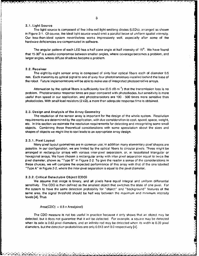
2.1. Light SourceThe light source is composed of five infra-red light emitting diodes (LEDs), arranged as shown
in Figure 2-1. Of course, the ideal liqht source would emit a parallel beam of uniform spatial intensity.Our less-than-ideal system nevertheless works impressively well, especially after some of thehardware deficiencies are compensated in software.
The angular pattern of each LED has a half cone angle at half intensity of 150. We have foundthat 15-300 is a useful compromise between smaller angles, where coverage becomes a problem, andlarger angles, where diffuse shadows become a problem.
2.2. ReceiverThe eight-by-eight sensor array is composed of sixty-four optical fibers each of diameter 0.5
mm. Each transmits its optical signal to one of sixty-four phototransistors installed behind the base ofthe robot. Future implementations will be able to make use of integrated photosensitive arrays.
Attenuation by the optical fibers is sufficiently low (0.5 dB-m') that the transmission loss is noproblem. Phototransistor response times are poor compared with photodiodes, but sensitivity is moreuseful than speed in our application, and phototransistors are 100 - 500 times more sensitive thanphotodiodes. With small load resistors (2 kQ), a more than adequate response time is obtained.
2.3. Design and Analysis of the Array GeometryThe resolution of the sensor array is important for the design of the whole system. Resolution
requirements are determined by the application, with due consideration to cost, speed, space, weight,etc. In this section we estimate the resolution requirements for detecting and recognizing some smallobjects. Combining these theoretical considerations with some speculation about the sizes andshapes of objects we might like to Sort leads to an appropriate array design.
2.3.1. Pixel LayoutMany pixel layout geometries are in common use; in addition many elementary pixel shapes are
possible. In our configuration, we are limited by the optical fibers to circular pixels. These might bearranged in rectangular arrays with various inter-pixel separation, or, in tessellated triangular orhexagonal arrays. We have chosen a rectangular array with inter-pixel separation equal to twice thepixel diameter, shown as "Type B" in Figure 2-2. To give the reader a sense of the considerations inthese chuices, we will compare the expected performance of this array with that of the one labelled"Type A" in Figure 2-2, where the inter-pixel separation is equal to the pixel diameter.
2.3.2. Critical Detectable Object (CDO)We assume that image is binary, and all pixels have equal integral and uniform differential
sensitivity. The CDO is then defined as the smallest object that switches the state of one pixel. Forthe system to have the same detection probability for "object" and "background" features of thesame area, the signal threshold should be half way between the maximum and minimum intensitylevels [4]. Thus
Area(CDO) = 0.5 x Area(pixel)
The CDO measure is not too useful in practice because it only shows that an object may bedetected, but it does not guarantee that it will be detected. For example, a square may be detectedwhen its side is 0.63 pixel diameters, and an infinite rod may be detected when its width is 0.39 pixeldiameters, but the detection probabilities are only 0.013 and 0.0 respectively [4].
- - - . / - '- . . .. ; . - . . -":.......... ... ..... .. .. ........ ... .. ... .- . .;. -

[., , + -:. -- .° . - ' "- .. L- .
-- - - -. .- . - ..- : I -. , - .. _ . .-I _, -.,+ _ ., - - - . . - ,,U
4
d- d
000000000000
TYPE A TYPE B
Figure 2-2: Two geometries for circular sensory cell arrays
2.3.3. Minimum Detectable Object (MDO)The MDO is the smallest object that can always be detected in any position on the sensor array.
Although MDO only means that the object can be detected and does not guarantee that it can berecognized, it is nevertheless a practically useful concept.
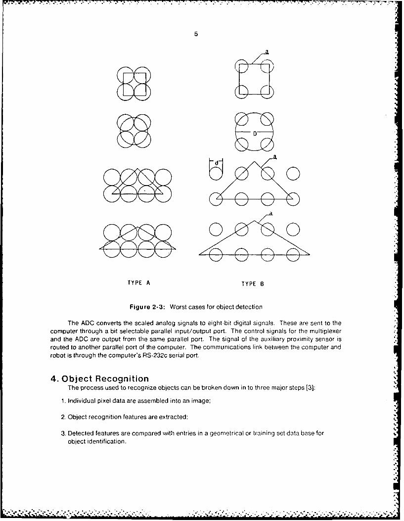
The MDO size for some generic shapes (discs, squares, triangles) have been analyzed. Theworst cases for detection of these objects are shown in Figure 2-3. The results of the analysis areshown in Figure 2-4. In our case (Type B), for example, to guarantee detection of a disc its diametermust be three times the diameter of the fiber. Similarly, to guarantee detection of a square of unit sidethe diameter of a fiber must be less than 0.42 units. This guarantees detection, but not identification:if a disc and square (or a disc and a hexagon) of the same area are to be differentiated, much higherresolution will in general be required. The most distinguishing feature between a disc and a square is
similar to a 900 isosceles triangle, and for a disc and a hexagon it is similar to a 1200 isoscelestriangle, as shown in Figure 2-5. Simple geometrical considerations based on Figure 2-5 lead to the
conclusion that a square and disc can be distinguished when D > 23.7d,where D is the disc diameter
and d is the pixel diameter. Similarly, a hexagon and a disc can be distinguished when D > 51.8d.Figure 2-4 shows some additional examples in graphic form. The last two table entries apply to
differentiating a disc and a square of the same area, as discussed.
In every case, noise and mechanical tolerances will ma , the real resolution requirement evenhigher.
3. HardwareOptical signals from the phototransistors are sent to the computer for data-driven data acquisi-
tion, control, and object recognition and sorting. The hardwa. e configuration to achieve this is shownin Figure 3-1.
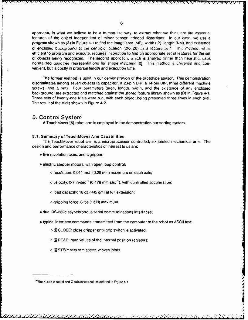
In our prototype design, based in part on being able to utilize existing resources, we mul-tiplexed the sixty-four phototransistor signals into a single amplifier, compensating for unit-to-unitvariation by individually selecting the phototransistor load resistors, R1 , in Figure 3.2. Resistor R3sets the average threshold for creating a binary image. Resistor R1 influences both the gain of the
amplifier and the response time of the phototransistors.
% ,--"I.v- 3-:. ., : ..- ' ..-4 . -. ,- ;-,-.-. .,--- ..v. .,. .. .-. . , .- , ._ . .-,. -- -.., .--. .--- -,. .-. ...-..-
5
TYPE A TYPE B
Figure 2-3: Worst cases for object detection
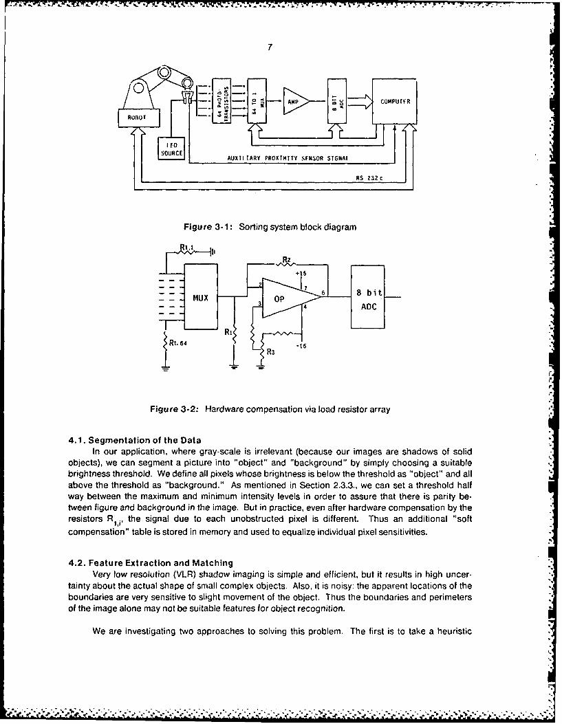
The ADC converts the scaled analog signals to eight-bit digital signals. These are sent to thecomputer through a bit selectable parallel input/output port. The control signals for the multiplexerand the ADC are output from the same parallel port. The signal of the auxiliary proximity sensor isrouted to another parallel port of the computer. The communications link between the computer androbot is through the computer's RS-232c serial port.
4. Object Recognition
The process used to recognize objects can be broken down in to three major steps 13]:
1. Individual pixel data are assembled into an image;
2. Object recognition features are extracted;
3. Detected features are compared with entries in a geometrical or training set data base forobject identification.
!,- -.

6
TYPE 0 0
OBJECTS ( X )00 0000 00
O=1.5d D=3. Od
0 0=1.Od D=2.Od
a=2.12d a=4.24d
a=2.58d a=5.16d
D=11.8d D=23.7dora=10.6d ora=21.2d
0=25.9d1 0=51.8dora= 14. 2d ora=28.3d
Figure 2-4: Minimum detectable objects for "Type A" and "Type B" arrays
D D
Figure 2-5: Critical features for distinguishing between a disc and a square,and a disc and a hexagon
The number of specific methods available for each step is large. Because our task is to recog-nize simple oblects rapidly. we chose the simplest adequate methods.
7
0,
RO-O- --
Ie,
AUXTI TARY PROXTMITY SFNSOR'SIGNAL
RS 232 c
Figure 3-1: Sorting system block diagram
Rt,4 ADCt -
±R !
Figure 3-2: Hardware compensation via load resistor array
4.1. Segmentation of the DataIn our application, where gray-scale is irrelevant (because our images are shadows of solid
objects), we can segment a picture into "object" and "background" by simply choosing a suitablebrightness threshold. We define all pixels whose brightness is below the threshold as "object" and allabove the threshold as "background." As mentioned in Section 2.3.3., we can set a threshold halfway between the maximum and minimum intensity levels in order to assure that there is parity be-tween figure and background in the image. But in practice, even after hardware compensation by theresistors Rij , the signal due to each unobstructed pixel is different. Thus an additional "soft
compensation" table is stored in memory and used to equalize individual pixel sensitivities.
4.2. Feature Extraction and MatchingVery low resolution (VLR) shadow imaging is simple and efficient, but it results in high uncer-
tainty about the actual shape of small complex objects. Also, it is noisy: the apparent locations of theboundaries are very sensitive to slight movement of the object. Thus the boundaries and perimetersof the image alone may not be suitable features for object recognition.
We are investigating two approaches to solving this problem. The first is to take a heuristic
8
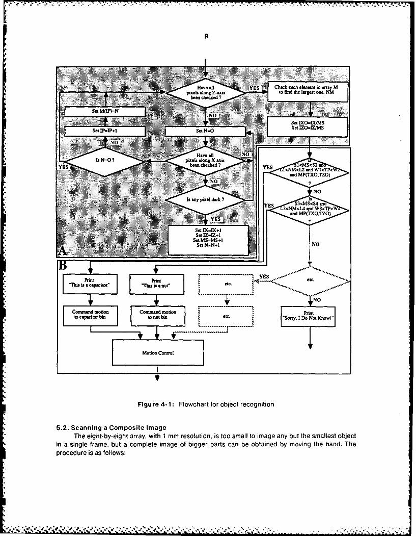
approach, in what we believe to be a human-like way, to extract what we think are the essentialfeatures of the object independent of minor sensor induced distortions. In our case, we use aprogram shown as (A) in Figure 4.1 to find the image area (MS), width (IP), length (NM), and existenceof enclosed background at the centroid location (IXOIZO) as a leature set 2. This method, whileefficient to program and execute, requires inspiration to find an appropriate set of features for the setof objects being recognized. The second approach, which is analytic rather than heuristic, usesnormalized quadtree representations for shape matching [2]. This method is universal and con-venient, but is costly in program length and execution time.
The former method is used in our demonstration of the prototype sensor. This demonstrationdiscriminates among seven objects (a capacitor, a 20-pin DIP, a 14-pin DIP, three different machinescrews, and a nut). Four parameters (area, length, width, and the existence of any enclosedbackground) are extracted and matched against the stored feature library shown as (B) in Figure 4-1.Three sets of twenty-one trials were run, with each object being presented three times in each trial.The result of the trials shown in Figure 4-2.
5. Control SystemA TeachMover [5] robot arm is employed in the demonstration our sorting system.
5.1. Summary of TeachMover Arm CapabilitiesThe TeachMover robot arm is a microprocessor controlled, six-jointed mechanical arm. The
design and performance characteristics of interest to us are:
* five revolution axes, and a gripper;
* electric stepper motors, with open loop control:
o resolution: 0.011 inch (0.25 mm) maximum on each axis;
o velocity: 0-7 in-sec 1 (0-178 mm-sec1 ), with controlled acceleration;
o load capacity: 16 oz (445 gm) at full extension;
o gripping force: 3 lbs (13 N) maximum.
* dual RS-232c asynchronous serial communications interfaces;
* typical interface commands; transmitted from the computer to the robot as ASCII text:
o @CLOSE: close gripper until grip switch is activated;
o @READ: read values of the internal position registers;
o @STEP: sets arm speed, moves joints.
2 The X-axis is radial and Z-axis is vertical, as defined in Figure 5-1
W--
w~ Have afl YES C2_ C = tI ant*I1
.. x.~ ~ been chocked ?
Set M(IP)=N . ,
Se N-
sSet IMPIZ+
Seb W1=S+ NOP
S.
ng .NO
Print Printttoi isCapacitor ins sa u" c
........................................4......
CoMotion Cotion
Figure 4-1: Flowchart for object recognition
* 5.2. Scanning a Composite ImageThe eight-by-eight array, with I mm resolution, is too small to image any but the smallest object
in a single frame, but a complete image of bigger parts can be obtained by moving thle hand. Theprocedure is as follows:

10
TillS IS A CAPACITOR. S:L:H- 103 16 8 THIS IS A SCRFW-#4-20. S:I :H- 88 8 23IHY AGAIN ? (Y/N)Y TRY AGAIN ? (Y/N)Y1111S IS A 20 PIN CIIIP. S:.:H- 118 26 8 TillS IS A SCRFW #5-13. S:I :11- 66 9 14IHY AGAIN ? (Y/N)Y IRY AGAIN Y (Y/N)Y11IS IA A 14 PIN CHIP. S:L:H 115 21 8 THIS IS A NUT. S:111- 1O 15 13
TRY AGAIN ? (Y/N)Y IRY AGAIN ? (Y/N)Y1111S IS A SCRFW-#3-7. S:I:Hw 14 3 7 THIS IS A CAPACITOR. S:I :H- 107 16 8
TRY AGAIN ? (Y/N)Y TRY AGAIN "? (Y/N)YTHIS IS A SCREW-#4-20. S:L:H- 70 8 21 TillS IS A 20 PIN CHIP. S:I::H. 115 25 8TRY AGAIN ? (Y/N)Y TRY AGAIN I (Y/N)YTillS IS A SCRFW-#5-13. S:L:H, 67 9 12 ..SQ*0
TRY AGAIN ? (Y/N)Y A.THIS IS A NUT. S:L:H- 108 15 13 THIS IS A SCREW-#3-7. S:I:1H- It 4 6TRY AGAIN ? (Y/N)Y TRY AGAIN ! (Y/N)YTillS IS A CAPACITOR. S:L:H- 109 16 8 THIS IS A SCRFW-#4-20. S:L:H- 82 8 221RY AGAIN ? (Y/N)Y TRY AGAIN ? (Y/N)YIHIS IS A 20 PIN CHIP. S:L:H- 112 25 8 THIS IS A SCRFW-#5-13. S:L:H- 65 9 13TRY AGAIN ? (Y/N)Y TRY AGAIN ? (Y/N)YTills IA A 14 PIN CHIP. S:L:H, 109 22 8 THIS IS A NUT. S:L_:H- 102 15 13TRY AGAIN ? (Y/N)Y TRY AGAIN ? (Y/N)N
1IllS IS A SCRFW-#3-7. S:L:H- 9 4 6 STOPTRY AGAIN ? (YIN)Y A,THIS IS A SCREW-#4-20. S.L:H- 97 9 24
TRY AGAIN ? (Y/N)YTHIS IS A SCRFW-#5-13. S:L:H= 75 9 15 THIS IS A CAPACITOR. S:L:N- 105 15 8TRY AGAIN ? (Y/N)Y TRY AGAIN ? (Y/N)YTHIS IS A NUT. S:L:H- 103 15 13 THIS IS A 20 PIN CHIP. S:L:H- 116 26 8
TRY AGAIN ? (Y/N)Y TRY AGAIN ? (Y/NJYTHIS IS A CAPACITOR. S:L:H- 118 16 9 THIS IA A 14 PIN CHIP. S:L:H- 110 21 8TRY AGAIN ? (Y/N)Y TRY AGAIN ? (Y/N)YTHIS IS A 20 PIN CHIP. S:L:H- 121 25 8 THIS IS A SCREW-#3-7. S:L:H- 13 4 6TRY AGAIN 7 (YiN)Y TRY AGAIN ? (Y/N)YTHIS IA A 14 PIN CHIP. S:L:H- 99 21 8 THIS IS A SCREW-#4-20. S:L:H- 92 9 22TR AGAIN ? (Y/N)Y TRY AGAIN I (Y/N)YTHIS IS A SCREW-#3-7. S:L:H= 11 4 6 THIS IS A SCREW-#5-l3. S:L:H- 61 9 13TRY AGAIN ? (Y/N)Y TRY AGAIN ? (Y/N)Y"'SQI* THIS IS A NUT. S:I.:H= 107 15 13
A. TRY AGAIN ? (.Y/N)YTHIS IS A SCREW-#5-13. S:L:1- 58 9 14 THIS IS A CAPACITOR. S:I.:H- 109 16 8TRY AGAIN ? (Y/N)Y TRY AGAIN ? (Y/N)YTHIS IS A NUT. S:L:H- 98 15 13 THIS IS A 20 PIN CHIP. S:L:H- 114 25 8
TRY AGAIN ? (YIN)N TRY AGAIN ? (Y/N)YSTOP THIS IA A 14 PIN CHIP. S:L:H- 108 21 8A. TRY AGAIN ? (Y/N)Y
THIS IS A SCREW-#3-7. S:L:H- 10 3 5
TRY AGAIN ? (Y/N)YTHIS IS A CAPACITOR. S:L:H- 105 15 8 THIS IS A SCREW-#4-20. S:L:H- 89 8 22TRY AGAIN ? (Y/N)Y TRY AGAIN ? (Y/N)YTHIS IS A 20 PIN CHIP. S:L:H- 116 25 8 THIS IS A SCREW-#S-13. S:L:H- 64 9 13
TRY AGAIN ? (Y/N)Y TRY AGAIN ? (Y/N)YTHIS IA A 14 PIN CHIP. S:L:H- 113 21 8 THIS IS A NUT. S:L:H- 104 15 13
TRY AGAIN ? (Y/N)Y TRY AGAIN ? (Y/N)YTHIS IS A SCREW-#3-7. S:L:H- 11 4 6 THIS IS A CAPACITOR. S:L:H- 114 16 9TRY AGAIN ? (Y/N)Y TRY AGAIN ? (Y/N)YTHIS IS A SCREW-#4-20. S:L:H= 82 8 22 THIS IS A 20 PIN CHIP. S:L:H- 112 25 8TRY AGAIN ? (Y/N)Y TRY AGAIN ? (Y/N)Y
THIS IS A SCREW-#5-13. S:L:H- 62 9 13 THIS IA A 14 PIN CHIP. S:L:H- 113 22 8TRY AGAIN ? (Y/N)Y TRY AGAIN ? (Y/N)YTHIS IS A NUT. S:L:H, 101 15 13 THIS IS A SCREW-#3-7. S:L:H- It 4 6TRY AGAIN ? (Y/N)Y TRY AGAIN ? (Y/N)YTHIS IS A CAPACITOR. S:L:H- 112 16 8 THIS IS A SCREW-#4-20. S:L:H- 83 8 22TRY AGAIN ? (Y/N)Y TRY AGAIN ? (Y/N)YTHIS IS A 20 PIN CHIP. S:L:H- 117 26 8 THIS IS A SCREW-#S-13. S:L:H, 70 9 14TRY AGAIN ? (Y/N)Y TRY AGAIN ? (Y/N)YTHIS IA A 14 PIN CHIP. S:L:H, 113 21 8 THIS IS A NUT. S:L:H- 106 15 13TRY AGAIN ? (Y/N)Y TRY AGAIN ? (Y/N)NTHIS IS A SCREW-#3-7. S:L:H- 10 4 6 STOPTRY AGAIN ? (Y/N)Y A.
Figure 4-2: Trial results (enclosed background check not printed out)
*6~'e

11
1. Check whether the image is complete, without regard to recognition; if incomplete,generate a strategy for moving the hand;
2. Read and calculate the old joint angles (B20 and B30 in Figure 5.1);
3. Evaluate the required new joint angles (B2 and B3 in Figure 5-1) to reach the desired newposition;
4. Check the composite image of the part again; if it is complete, command the robot tomove. the hand to the middle of the part (or other suitable gripping point); if not, go backto step(2).
Zx
M1 MoWX
Figure 5-1: Simplified three-link articulated manipulator
5.3. Motion ControlMotion control is simple, because the TeachMover arm uses stepper motors, and open-loop
control is usually adequate:
1. The computer issues a robot motion command, e.g. @CLOSE, @STEP.
2. After executing the motion, the TeachMover arm sends an acknowledgement signal to
the computer, signalling that it is ready for next command;
3. Repeat steps (1) and steps (2) until task execution is finished.
If an obstacle is encountered by the proximity sensor, an interrupt will be generated, causingthe compiter to command an avoidance maneuver.
6. ConclusionA simple, low cost small parts sorter based on "smart fingers" has been developed and
demonstrated. The system uses an eight-by-eight optical fiber array with 1 mm resolution. It canrecognize and sort parts larger than the array itself by scanning and assembling a composite image.
Because the sensor array is located in the fingers, the information content per bit is very high,and a very small number of bits is usually sufficient for part recognition. The data-base of parts cansimilarly be stored very compactly, and very efficient identification algorithms can be executed in alimited capability microcomputer. The heuristic approach to extracting essential features for objectclassification is attractive and efficient. The ability to use auxiliary sensors to interrupt and affectmotion control is an especially flexible way to deal with obstacles along the intended trajectory.
"- "" '""".'-
12
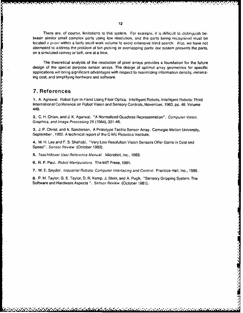
There are, of course, limitations to this system. For example, it is difficult to distinguish be-tween similar small complex parts using low resolution, and the parts being recognized must belocated a pitori within a fairly small work volume to avoid extensive blind search. Also, we have notattempted to address the problem of bin-picking or overlapping parts: our system presents the parts,on a simulated convey or belt, one at a time.
The theoretical analysis of the resolution of pixel arrays provides a foundation for the futuredesign of the special purpose sensor arrays. The design of optimal array geometries for specificapplications will bring significant advantages with respect to maximizing information density, minimiz-ing cost, and simplifying hardware and software.
7. References1. A. Agrawal. Robot Eye-In-Hand Using Fiber Optics. Intelligent Robots, Intelligent Robots: ThirdInternational Conference on Robot Vision and Sensory Controls, November, 1983, pp. 48. Volume449.
2. C. H. Chien, and J. K. Agarwal. "A Normalized Quadtree Representation". Computer Vision,Graphics, and Image Processing 26 (1984), 331-46.
3. J. P. Christ, and A. Sanderson, A Prototype Tactile Sensor Array. Carnegie-Mellon University,September, 1982. A technical report of the C-MU Robotics Institute.
4. M. H. Lee and F. S. Shahabi. "Very Low Resolution Vision Sensors Offer Gains in Cost andSpeed". Sensor Review (October 1982).
5. TeachMover User Reference Manual Microbot, Inc., 1982.
6. R. P. Paul. Robot Manipulators. The MIT Press, 1981.
7. W. E. Snyder. Industrial Robots: Computer Interfacing and Control. Prentice-Hall, Inc., 1985.
8. P. M. Taylor, G. E. Taylor, D. R. Kemp, J. Stein, and A. Pugh, "Sensory Gripping System: TheSoftware and Hardware Aspects ". Sensor Review (October 1981).
hoc&'

F APPENDIX
C MAIN ROUTINE FOR SORTERDIMENSION MP(40,40),MD(8,8),M(40),NAM(6)COMMON /CR/VE,1HO/PF/NI,NJ,MP,MD/RU/JJ,NAMSMS,NM,IP,IBICCALL OUT(80,144)WRITE(5,6)
6 FORMAT(IX,'DISTANCE(5000--15000):')READ(5,7) IDIS
* 7 FORMAT( 16)WRITE( 5,8)
8 FORMAT(lX,'INTERVAL(500--1500):')READ(5,7) INTVWRITE(5,9)
9 FORMAT(IX,'CALIBRATE ? (YIN)')READ(5,1O) IC
*10 FORMAT(A1)IF(IC.EQ.'N'.OR.IC.EQ.'n') GO TO 15CALL INIT
11 WRITE(5.12)12 FORMAT(1X.'READY ? (Y/N)')
READ(5,13) ID*13 FORMAT(A1
IF(ID.EQ.'N'.OR.ID.EQ.'n') GO TOl1115 DO 24 1=1.40
DO 26 J=1,40MP(I ,J)='o'
26 CINTINUE*24 CONTINUE
Ix=OJY= 0MS 0NM= 0IP=0NI=ONJ= 0NJ 1=0
25 IP1=OI=40
C MOVE HANDS UP TO AVOID MISSLEADING BY ALUMINUM BLOCKCALL PEK
28 IP1=IP1+1DO 30 J=1,8IF(MP(IJ).EQ.'o') GO TO 50
30 CONTINUEI=1-1IF(IPI.GE.8) GO TO 50GO TO 28
50 VE=FLOAT(IP1)-0.5HO=0.CALL CRUN
14
C MOVE HANDS IATERRAL!Y rO ONE EDGE O[ IMAGE150 CAl L PFK
DO 155 J=1,8DO 158 1=33.40Jp=J
.9 IF(MP(I,J).EQ. -') GO TO 160158 CONTINUE155 CONTINUE
WRITE(5.790) ((MP(I,J),J=1.8) .1=33,40)790 FORMAT(1X,8A2)
GO TO 450160 IF(JP.EQ.1) GO TO 165
VE=O.HO=FLOAT(JP)-1.5CALL CRUNGOTO 65
165 HO=-4.0VE=0.CALL CRUNGO TO 150
C SCAN COMPOSITE IMAGE65 CALL PEK
J=8*(NJ+1)K=33-NI*8Kl=K+7DO 70 I=K,KIIF(MP(I,J).EQ.2*') GO TO 80
70 CONTINUEI=KK=J
95 00 75 J=1,KIF(MP(I,J).EQ.'*') GO TO 85
75 CONTINUEGO TO 100
80 NJ=NJ+1IF(NJ.GT.NJI) NJI=NJIF(NJ.EQ.5) GO TO 300HO=8.0VE=0.0CALL CRUNGO TO 65
85 NI=Nl+1IF(NI.EQ.5) GO TO 300HO=O.OVE=8.0CALL CRUNIF(NJ.GT.O) GO TO 90GO TO 65
*90 CALL PEKHO=-8.OVE=O.OCALL CRUNNJ=NJ-1IF(NJ.GT.O) GO TO 90CALL PEK

15
1=33-NI*8K=8*(NJI+1)GO TO 95
300 WRITE(5,3O5)305 FORMAT(IX,2TOO BIG!')
C MOVE HANDS TO THE MIDDLE OF THE OBJECT100 Kl=8'(NJ1+1I)
K2=33-N1*8NJ2=NJ1+1
500 IF(NJI.EQ.0.AND.NI.EQ.0) GO TO 510VE=-FLOAT(NI*8)+1. 5HO=FLOAT( NJI-4)IF(NJ1.EQ.O) HO=0.0IF(NJ.GT. 0) HO=-(HO-(NJ1-NJ)*8)CALL CRUN
*C EXTRACT FEATURES OF OBJECT*510 DO 130 I=K2.40
N=0DO 140 J=1,KlIF(MP(I,J).NE..*') GO TO 140IX=IX+IJY~JY+JMS=MS+1N=N+l
140 CONTINUEIF(N.EQ.0) GO TO 130IP=qp+iM( IP)=N
130 CONTINUEDU 132 J=1,KIDO 134 I=K2.40IF(MP(IJ).EQ.'*') GO TO 136
134 CONTINUEGO TO 132
136 NM-NM+1132 CONTINUE
IX0= IX /MSJYO=JY/MS
C OBJECT IDENTIFICATIONIF(MS.GE. 70 .AND.MS. LE.140 .AND.NM.GE. 1- .AND. NM. LE. 17 .AND.
I IP.GE. 7.AND.IP.LE.15 .AND.MP(IXOJYO).EQ"') GO TO 210IF(MS.GE. 80.AND.MS.LE.150.AND.NM.GE .23.AND.NM. LE.28.AND.
I IP.GE. 6.AND.IP.LE. 9) GO TO 220IF(MS.GE. 50.AND.MS.LE. 120.AND.NM.GE. 18.AND.NM.LF.22.AND.
1 IP.GE. 6.AND.IP.LE. 9) GO TO 230IF(MS.GE. 2.AND.MS.LE. 30.AND.NM.GE. l.AND.NM.LE. 8.AND.
1 IP.GE. l.AND.IP.LE. 8) GO TO 240IF(MS.GE. 50.AND.MS.LE. 110.AND.NM.GF. 5.AND.NM.LE. 10.AND.
1 IP.GE. 19.AND.IP.LE. 26) GO TO 250IF(MS.GE. 30.AND.MS.LE. 100.AND.NM.GE. 5.AND.NM.LE. 1l.AND.
1 IP.GE. 6.AND.IP.LE. 18) GO TO 260IF(MS.GE. 60.AND.MS.LE.120.AND.NM.GF. 12.AND.NM.LE.18.AND.
I IP.GE. 11.AND.IP.LE. 15) GO TO 270

16
GO TO 460210 JJ,1fl1S+t*INTV
NAM( I)= 'CA'NAt4(2) 'PA'
NAM(4)='TO'NA?(5)='R.NAM(6)-'IC=51GO TO 420
220 JJ=IDIS+2*INTVNAM( l)='20'NAI(2)=' P'NAM(3)=1N'NAM(4)=' C'NAM(5)= HI'NAM(6)='P.'IC=48GO TO 420
230 JJ=IDIS+3*INTVNAM( 1)=' 14'NAM(2Y=' P'NAM(3)= IN'NAt(4)=' C'NAM(5Y 'HI'NAM(6)='P..'IC=48GO TO 420
240 JJ=IDIS+44NTVNAM( 1)-'TH'NAI4(2)='RE'NAM(3)= AD'
NAM(5V='7.'NAM(6)='IC=53GO TO 420
250 33lIDlS+5*INTVNAM( 1)='TH'NAM(2)='RE'NAM(3)='AD'NA4( 4) =' --
NAM(5)='20'NAM(6)='.ICs50GO TO 420
260 JJ=IDIS+6*INTVNAMIl)='TH'NAM(2)='RE'NAM(3)='AD'NAM(4)= -- 'NAM(5)= 13'NAI4(6)='.1C49GO TO 420
270 JJ=IDIS+7*INTV

17
NAM( 1)=NU'NAM(2) = T.NAM(3) 'NAM(4) =NAM(5) =IAM(6) =IC=49GO TO 420
460 WRITE(5.465) MS,NM,IP465 FORMAT(1X.316/1X,'SORRY, I DO NOT KNOW I-)
GO TO 430420 CALL SSRUN430 VE=-3.5
H0=-FLOAT(NJl#4)CALL CRUNGO TO 600
450 WRITE(5,455)455 FORMAT(1X,'NOTHINGI ')600 WRITE(5,470)470 FORMAT(1X,'TRY AGAIN ? (YIN)')
READ(5.475) IB475 FORMAT(Al)480 IF(IB.EQ.'N'.OR.IB.EQ.'n') GO TO 700
GO TO 15700 STOP
END
C SUBROUTINE FOR INITIALIZATION OF ROBOT ARMSUBROUTINE INITDIMENSION IRD(6),ID(30),ISTP(9),ISTSH(5),ISTEL(12),
I ISTO(2) ,IBAK(15),IH1(17), ISTP1(9) ,IRSET(7),IRDY(16),2 ISH(5) ,IBR(5),IBL(3),IUP(5)
DATA IRD/64,82,69,65,68, 13/,ISTP/64,83,84,69,80,49,49,49,1 44/,ISTSH/44,52,48,48, 13/,ISTELI44,44,51,48,48,44,44,44,2 51,48,48, 13/,ISTO/48, 13/,IBAK/44,45,52,48,44,45,54,48,44,3 44,44,45,54,48,13/, IH/44 ,54 .56,50,44,45,57,57,52,44,44,444 .45,57,57,52,13/, ISTPl/64,83,84,69,80,52,48,48,44/,IRSET/5 64,82,69,83,69,84,13/, IRDY/44 ,45 .49,51,50,44,52,49,51.44,6 44,44,52,49,51, 13/,ISH/44,48,50,50,13/, IBR/45,57,57,57. 137 /,IBL/53,48,13/,IUP/44,45,53,48,13/
IREP=OM1=oM2 =0CALL SOUT(ISTP,9)CALL SOUT(ISTSH.5)
215 NI=INP( 100)IF (NI.EQ.0) GO TO 215MI=MI+1IF(MI.LE.100) GO TO 215CALL SOUT(ISTP,9)CALL SOUT(ISTO,2)

18
CALL. RFINCALLt. REMNCALL SOUT(ISTP,9)CAll. SOUT(IBR,5)
220 N2=JNP( 100)IF (N2.EQ.64) GO TO 220!42=M2+1IF (M2.LE.50) GO TO 220CALL SOUT(ISTP,9)CALL SOUT(ISTO,2)CALL REINCALL REINCALL SOUT(ISTP,9)CALL SOUT(IBL,3)CALL REINCALL SOUT(ISTP,9)CALL SOUT(IUP,5)CALL REIN
50 IREP=IREP+lMl=OM2=0CALL SOUT(ISTP,9)CALL SOUT(ISTSH,5)
217 N1=INP( 100)IF(N1.EQ.0) GO TO 217MI=MI+1IF(M1.LE.1000) GO TO 217CALL SOUT(ISTP,9)CALL SOUT(ISTO,2)CALL REINCALL REINCALL SOUT(ISTP,9)CALL SOUT(ISTEL,12)
222 N2=INP(100)IF(N2.EQ.64) GO TO 222M2=M2+1IF(M2.LE.50) GO TO 222CALL SOUT(ISTP,9)CALL SOUT(ISTO,2)CALL REINCALL REIN
CALL SOUT(IRD,6)DO 70 I=1,30I0( I)=INP(81)DO 80 J=1,13G=2*6
80 CONTINUE*70 CONTINUE
IF(IREP.EQ.3) GO TO 250CALL SOUT(ISTP.9)CALL SOUT(IBAK,15)CALL REINGO TO 50
250 CALL SOUT(ISTP1,9)

19
CALL SOUIRAK,15)CALL REINCAL.L SOUT(ISTPI,9)CALL SOUT(III,17)CALL REINCALL SOUT(IRSET.7)CALL REINCALL SOUT(TSTP1,9)CALL SOUT(IRDY,16)CALL REINRETURNEND
C SUBROUTINE TO BINARY IMAGESUBROUTINE PEKINTEGER H.PDIMENSION MD(8,8).MP(40.40)COMMON /PE/NTNJMP,M)
DO 10 1=1.8DO 20 J=1,8
CALL OUT(84.N)Nl=N+64DO 30 P=1.6F=2*6
30 CONTINUECALL OUT(84,Nl)CALL OUT(84.N)MD( I,J)=INP(84)IF(MD(I,J) .LT.0) MD(I.J)=256+MD(I .3)K=I+32-NI*8H=J+NJ*8MP( K,H)= '0'MEN= 120IF(I.EQ.1.AND.J.EQ. 1.OR.I.EQ. 1.AND.J.EQ.2) MEN=13IF(I.EQ.3.AND.J.EQ.8.OR.I.EQ.1.AND.3 EQ.3.OR.1I.EQ.8.AND.J.EQ.4.OR. I.EQ.8.AND.J. EQ. 7) MEN=35IF(I.EQ.2.AND.J.EQ.7.OR.I.EQ.7.AND.3 EQ.8.OR.II.EQ.4.AND.J.EQ.2.OR.I .EQ.3.AND.J.EQ. 7) MEN=50IF(I.EQ.7.AND.J.EQ..IEQ2ANDJEQ.8OR.1I.EQ.4.AND.J.EQ.8.OR. I.EQ.8.AND.J.EQ. l.OR.
2 I.EQ.4.AND.J.EQ.7.OR. I.EQ.2.AND.J.EQ.2.OR.3 I.EQ. 1.AND.J.EQ.4.OR. I.EQ.2.AND.J.EQ.3) MEN=75
IF(I .EQ.2.AND.J.EQ.5.OR. I.EQ.8.AND.J.EQ.6) MEN=85IF(MD(I.3) .LT.MEN) MP(K,H)='*'
20 CONTINUE10 CONTINUE
RETURNEND
20
C SUBROUTINE FOR HANDSHAKINGSUBROUTINE REINDO 10 J=1,16DO 20 1=1,32222NI=INP(81)IF(NI.EQ.49) GO TO 60IF(NI.EQ.48) GO TO 30
20 CONTINUE10 CONTINUE30 WRITE(5,40)40 FORMAT(IX,'WRONGH'-)60 RETURN
END
C SUBROUTINE TO MOVE HANDS ACCORDING VE(VERTICAL) AND HO(HORIZONTAL)SUBROUTINE CRUNDIMENSION IRD(6) .ID(40) ,ND(8) ,ISTP(9) ,NB(4) .IS(18)COMMON /CR/VE,HODATA IRD/64,82,69,65,68, 13/,ISTP/64,83,84,69,80,50,50,48,44/,
1 IS(l).IS(6),IS( 1I),IS(12),IS(13),IS(18)/5*44,13/CALL SOUT(IRD,6)DO 70 I=1.40ID( I)=INP(81)DO 80 J=1,14F=2*6
80 CONTINUE70 CONTINUE
IF (ID(2).EQ.48) GO TO 500NK2=0NK4=0NK3=1DO 90 I=4,36IF (ID(I)-45) 230,210,200
200 NK4=NK4+1NB(NK4)=lD( I)-48GO TO 90
210 NK3=-lGO TO 90
230 NK2=NK2+1GO TO (205,206,207,208),NK4
*205 ND(NK2)=NK3*NB(l)GO TO 240
206 ND(NK2)=NK3*(NB(1PlIO+NB(2))GO TO 240
207 ND(NK2)=NK3-(NB( I)*100+NB(2)*10*N3(3))GO TO 240
*208 ND(NK2)=NK3*(NB( l)t000+-NB(2)*l00+NB(3)*10+NB(4))240 IF (NK2.EQ.6) GO TO 250
21
NK3= 14 NK4=0
CO CONTINUE250 D2=FI.OAT(ND(2))*3.1416/3536.O
D3=F[.OAT(ND(3))*3. 1416/2079.0Al=SIN(DZ)+SIN(r)3)-VE/177 .8Bl=COS(D2)+COS(D3)-HO/17 7.8
Cl=ATAN(CI)C3=4.0-(Al*A1+81*B1-2 .0)C2=(Al*Al+BI*Bl-2 .O)/SQRT(C3)C2=2.O*ATAN( 1.O)-ATAN(C2)El=(Cl+C2)*1039.0/3. 1416NEI=INT(E1+O .5)-ND(3)E2=( CI-CZ)1768. 0/3 .14 16NE2=INT(E2+ . 5)-ND(2)IF(NE2.LT.0) GO TO 345IS(2)=48GO TO 346
345 IS(2)=45346 IF(NEI.LT.O) GO TO 348
IS(7)=48IS(14)=48GO TO 349
348 IS(7)=45IS( 14)=45
349 NE1=IABS(NEl)NE2=TABS(NE2)IS(3)=INT( FLOAT(NE2/100) )+48IS(8)=INT( FLOAT(NEl/100) )+48IS( 15)=IS(8)IS(4 )=INT( FLOAT( NE2/1O ) )-( IS( 3) -48)* 10+48IS(9)=INT(FLOAT(NEl/10))-(IS(8)-48)*1O+48IS( 16)=IS(9)IS(5)=INT(FLOAT(NE2))-(IS(3)-48)*10O-(IS(4)-48)*1O+48IS( 10) =INT( FLOAT(NEI) )-( IS( 8) -48 )*100-( IS(9)-48)* 10+48IS( 17)-IS( 10)CALL SOUT(ISTP,9)CALL SOUT(IS.18)CALL REINGO TO 510
500 WRITE(5,110)110 FORMAT(lX,'WRONG! ')510 RETURN
END
C SUBROUTINE TO COMMAND ROBOTSUBROUTINE SOUT(I0,NDIM)DIMENSION IO(NDIM)DO 10 I=1,NDIMCALL OUT(81,IO(I))DO 15 J=1,16
22
15 CONTINUE*10 CONTINUE
RETURNEND
C SUBROUTINE FOR MOTION CONTROLSUBROUTINE SSRUNDIMENSION IC[S(7),ISTP(9),ISTIO(18),ISTI(18),IST2(5),IST3(15)
1 .IST4(9),IST6(6) ,IST20(6),ISTO(2).NAM(6)COMMON /RU/JJ.NAMMS,NM,IPIB,ICDATA ICLS/64,67.76,79.83,69, 13/,ISTP/64,83,84,69,80,50,50,48.
1 44/,IST2/50,53,48,48, 13/,ISTI/44,45,51,48,48,44,45,49,48,48.2 44,44,44,45,49,48,48, 13/,IST3/44,49,48,48,44,49.48,48,44,44,3 44.49,48,48,13/,IST4/44,44,44,44,44,50,48,48, 13/,IST6/45,50.4 53,48,48, 13/,ISTIO/44,45,48,50,48,44,45,48,50,48,44,44,44,45.
* 5 48,50,48, 13/,IST2O/45,48,48,48,52,13/.ISTO/48, 13/N1=ON4=0N6=0N8 =0IST4(7)=ICCALL SOUT(ICLS,7)CALL REINCALL SOUT(ISTP,9)CALL SOUT(IST1,18)CALL REIN
*210 CALL SOUT(ISTP,9)CALL SOUT(IST2,5)
215 Nl=Nl+lF=50**3N2=INP( 100)IF(NI.GE.JJ) GO TO 250IF(N2.EQ.0) GO TO 215CALL SOUT(ISTP,9)CALL SOUT(ISTO,2)CALL REINCALL REINN8=N8+1JJ=JJ+275
220 CALL SOUT(ISTP,9)CALL SOUT(IST1O, 18)CALL REINN4=N4+1N2=INP( 100)IF(N2.NE.0) GO TO 220
*230 CALL SOUT(ISTP,9)CALL SOUT(IST1O,18)CALL REINN6=N6+1IF(N6.EQ.2.OR.N6.EQ.4.OR.N6.GE.6) GO TO 210

23
GO T0 230250 CAII s(,u ( is ri, 9)
CALL[ SUUr(lSro,2)CALL. REINCALL REINIS1=(N4+N6)*21S4=I/ 10IS2=49+IS4IS3=48+ISl-IS4*10IST3(2)=IS2TST3(3)=IS3IST3(6)=IS2IST3( 7)=1S3IST3( 12)=IS2IST3( 13 )=IS3CALL SOUT(ISTP,9)CALL SOUT(IST3,t5)CALL REINWRITE(5,260)(NAM(I),I-l,6),MS,NM,IP
260 FORMAT(1X,'THIS IS A ',6A2,' S:L:H=z',31G)CALL SOIJT(ISTP,9)CALL SOUT(IST4,9)CALL REINISTI(3)=JS2
IST1(8)=IS2IST1(9)=IS3ISTI( 15) =1S2ISTI( 16)=1S3CALL SOUT(ISTP,9)CALL SOUT(ISTl,18)CALL REINNI=0JJ=JJ-N8*275IST3(2)=S2+2CALL SOUT(ISTP.9)CALL SOUT(IST6,6)
270 Nl=Nl+lF=50**3N2=INP( 100)IF(NI.GE.JJ) GO TO 280IF(N2.EQ.O) GO TO 270IF(N2.NE.0) GO TO 270
280 CALL SOUT(ISTP,9)CALL SOUT(IST0,2)CALL REINCALL REINCALL SOUT(ISTP,9)CALL SOLJT(IST3,15)CALL REINlST3(2)z49IST3(3)=48IST3(6)=49IST3(7)=48IST3( 12)=49IST3( 13)=48
24
ISTI(3)=G17STI(4)=48IST1(8)=49ISTI(9)=48TSTI( 15)=49ISTI( 16)=48WRITE( 5.290)
290 FORMAT(IX,'RETURNEND
* -~'.. .- ~ .-. '- - . - - -~ .A. - . -
.'
j.1.
* %* *.
'I~
I.'
'-C.
*1~* -
-.---- ~-
Cr.
.- C.
% 4
(C..
~ ~ *** *C.% ~ C..