Embed Size (px)
Citation preview

1-Saddle CNC Lathe

1
Birth of the LB that transcends LBOkuma's LB series of NC lathes have always been pioneers,
leaving a path for others to follow behind.The LB series thus has an obligation to respond to the needs of the times, open
possibilities for the next generation, and deliver new value to customers worldwide. That means constantly developing LBs that transcend LB.
Okuma's advanced technology in its SPACE TURN EXII series continues to write new pages in world standards for machining quality, speed, power & torque,
multitasking, ease of operation, and more.
Photo includes optional specifications.
2
� Satisfaction from complete control of a machine tool
� Operator-friendly OSP-P300L
The machine against whichall others will be measured
� Application of Thermo-Friendly Concept
� Slanted-box bed construction
Highest Quality
� Equipped with new high-power, high-torque motor
� Combination of larger and faster spindle
� Large through-hole diameter, large working range
� Top rotation speed, horsepower, and torque in its class
Super Rigidity Speed
Easy Operation
� Abundant series variation
� NC tailstock standard equipment
Extreme Versatility

3
0
-5
0
5
10
2 4 6 8 10 12
Elapsed time (Hr)
OD
cha
nge
(øµm
)
14 16 18
OD dimensional change Ambient temperature change
ø5µm
8C° changeRoomtemp
Machining dimensional change
over time: ø5 m*
Actual data [LB2000 EX (L) turning] (ambient temperature: 8C° change)
Highest Quality
* ø0.0002 in.
� Cycle time: 60 sec
� Cutting conditions
� Workpiece material: BsB
X-axis travel: 60 mm3 repetitions/cycle
Spindle speed: 4,000 min-1
Cutting depth : 0.1 mmFeed : 0.05 mm/rev
4
High accuracy specifications overall assuremachining with high thermal stability
Thermo-Friendly Concept forunparalleled thermal stability
Slanted-box bed configuration withsuperior construction and rigidity
Optimized X-axis feed element
Thermal deformation minimized on Z-axis
Slanted-box bed achieves outstanding thermal stability and high rigidity
�Roundness [actual data*] �Tool nose uniformity* (for better surface roughness) [actual data*]
Material: BsBStandard spindle
Material: BsB
0.4 µm
2,500 min-1
0mm-4.0
-2.0
0.0
2.0
4.0
(µm)
1.00
0.3 µm
2.00 3.00
2,500 min-1 Outer perimeter
Okuma's Thermo-Friendly Concept is used on all the LB EX machines for extraordinary machining accuracy, using our unique machine design and thermal deformation control technology. Outstanding thermal stability in long-time continuous operation, multitasking, front and back side machining with a subspindle, and even Y-axis machining without troublesome compensation or warming up.
The next evolution of the slanted-box bed construction that has been highly praised as a "rugged, Okuma-like construction" in the SPACE TURN series. The primary units of headstock and turret on a box bed is optimally placed for outstanding thermal stability and high rigidity. Exhibits stable machining accuracy even in heavy cutting.
Heat sources eliminated and thermal deformation suppressed from the machine's construction
0.4 µm/at 2,500 min-1
� Standard spindle� Standard spindle: 0.3 µm/at 2,500 min-1
Thermo-Friendly Concept
Simple machlneconstructionSymmetrically built
Thick walls
Highly accurate control technology
(on MY machines only)TAS-C
Machine designs thatequalize ambient
temperaturesMachine covers
Peripheral equipment placementMachine “hot spots” diffused
Thermo-FriendlyConcept
* The “actual data” referred to above for this brochure represent examples, and may not be obtained due to differences in specifications, tooling, cutting and other conditions.

Super Rigidity Speed
Improved productivity: 20% shorter cycle time*
0 500 (Sec)
Turning Milling
Workpiece
6-M8, 20 deep2885
Previous machine
LB2000 EX
Non-cutting time
2.8 minutes (20% less)
14.7 minutes
11.9 minutes ø100
ø35
* Previous machine comparisonActual data
5
Spindle with a larger bearing internal diameter of ø100 mm can accommodate larger workpieces, and a turning capacity of 2.7 mm2 is achieved with a high-speed, wide-area full power motor. Stable, high quality machining, from heavy to high speed cutting.
Cylindrical, heavy-duty cutting
Drilling
Bearing ID ø100 (bore ø62)
6,000 min-1
11/7.5 kW (15/10 hp)
160 N-m (118 ft-lbf)
Integral motor/spindle—Okuma's own powerful motor—retains full power over a wide area. There are no gears or belts that can cause vibration or bending, for stable machining without chatter.
X: 25 m/min (984 ipm)
Z: 30 m/min (1,181 ipm)
3.4 sec (6,000 min-1)
0.1 sec/index
12 m/min (472 ipm)
Standard spindle High power specs Big bore spindle specs
ø100, 6,000 min-1
11/7.5 kW (20 min/cont)160 N-m (118 ft-lbf)
ø100, 6,000 min-1
15/11 kW (15 min/cont)202 N-m (149 ft-lbf)
ø120, 5,000min-1
22/15 kW (30 min/cont)427 N-m (314 ft-lbf)
Turning 2.7 mm2
(Workpiece: S45C)
� Spindle size
� Rapid traverse
� Spindle start/stop
� Turret rotate
� NC tailstock rapids
� Spindle speed
� Output
� Torque
Motor/spindle variations
Huge reduction in machining time with an original high power motor and faster machine movements
Powerful motor on the spindle gives turning capacity of 2.7 mm2
Reduced operation time achieved with higher speed machine movements
2.7 mm2 (0.0042 in.2)Cutting speed V: 120 m/min (393 fpm)Cutting depth t : 6.0 mm (0.24 in.)Feedrate f : 0.45 mm/rev (0.02 ipr)
ø30 (ø1.18) carbide insert drillCutting speed V: 150 m/min (492 fpm)Feedrate f : 0.22 mm/rev (0.01 ipr)
[Actual data*](15/10 hp)
Motor output 11/7.5 kW
ø140 flat
ø62
ø10
0
* The “actual data” referred to above for this brochure represent examples, and may not be obtained due to differences in specifications, tooling, cutting and other conditions.
6
50 100 500 1,000 5,000
500
1,000
300
100
50
10
50
30
10
5
1
660 1,600
7.5 kW (cont)
6,000
Spindle speed
50 100 500 1,000 5,000
500
1,000
300
100
50
10
50
30
10
5
1
710 1,900 6,000
Spindle speed
22 kW (30 min)
15 kW (cont)
50 100 500 1,000 5,000
500
1,000
300
100
50
10
50
30
10
5
1
51045 1,100
4,500
427 N-m (10 min)346 N-m (20 min)
Spindle speed
22.8 kW (10 min)
18.5 kW (20 min)
11 kW (20 min)160 N-m (20 min)
109 N-m (cont)
66 N-m (20 min)
45 N-m (cont)
202 N-m (15 min)
148 N-m (cont)
75 N.-m (15 min)55 N-m (cont)
15 kW (20 min)
11 kW (cont)
281 N-m (cont)
191 N-m (30 min)
130 N-m (cont) 15 kW (cont)
Torq
ue
N-m kW
Out
put
Torq
ue
N-m kW
Out
put
Torq
ue
N-m kW
Out
put
7 8
Compact, high-power, high-torque PREX motor also used for milling spindle of the multitasking V12 radial turret. This combined with a powerful, highly rigid bolt clamp system greatly increases multitasking speed.
6,000 min-1
PREX 5.5/3.7 kW (7.5/5 hp)
31.3/20.9 N-m (23/15.4 ft-lbf)
ø140 flat 6-in. chuck
8-in. chuck
10-in. chuck
JIS A2-6
0.1 sec/ index
0.4 sec (6,000 min-1)
1.2 sec
Wide working range
Max machining dia: ø430 mm (M turret: ø360 mm)
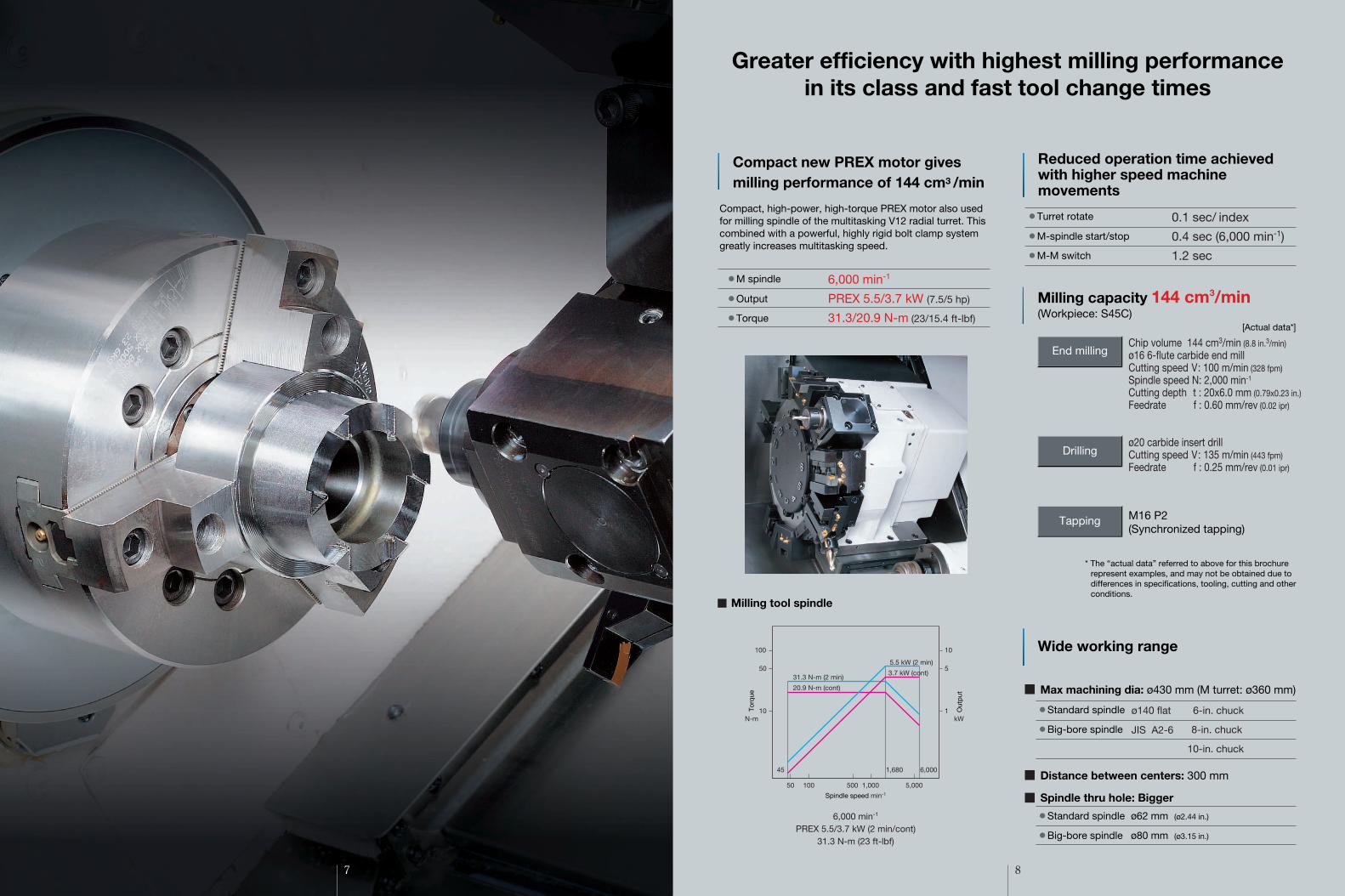
6,000 min-1
PREX 5.5/3.7 kW (2 min/cont)31.3 N-m (23 ft-lbf)
End millingChip volume 144 cm3/min (8.8 in.3/min)ø16 6-flute carbide end millCutting speed V: 100 m/min (328 fpm)Spindle speed N: 2,000 min-1
Cutting depth t : 20x6.0 mm (0.79x0.23 in.)Feedrate f : 0.60 mm/rev (0.02 ipr)
Drillingø20 carbide insert drillCutting speed V: 135 m/min (443 fpm)Feedrate f : 0.25 mm/rev (0.01 ipr)
Tapping M16 P2(Synchronized tapping)
Spindle thru hole: Bigger
Distance between centers: 300 mm
� M spindle
� Output
� Torque
� Turret rotate
� M-spindle start/stop
� M-M switch
Milling capacity 144 cm3/min(Workpiece: S45C)
Milling tool spindle
� Standard spindle
� Big-bore spindle
Greater efficiency with highest milling performance in its class and fast tool change times
Compact new PREX motor gives milling performance of 144 cm3 /min
Reduced operation time achieved with higher speed machine movements
� Standard spindle ø62 mm (ø2.44 in.)
� Big-bore spindle ø80 mm (ø3.15 in.)
[Actual data*]
* The “actual data” referred to above for this brochure represent examples, and may not be obtained due to differences in specifications, tooling, cutting and other conditions.
Out
put
Torq
ue
50 100 500 1,000 5,000
100
50
10
10
5
1
1,68045 6,000
N-m kW
5.5 kW (2 min)
31.3 N-m (2 min)
20.9 N-m (cont)
3.7 kW (cont)
Spindle speed min-1

OSP-P300L Okuma Sampling Path ControlOkuma Control
[for Lathes]
Easy Operation
As a “machine & control” builder, Okuma makes further strides in machine tool manufacturing with this superb control featuring “Easy Operation.” Okuma took a close look at the way machinists actually operate machine tools, to help them create smoother and more effective ways of producing parts. Novice operators as well as professional machinists get complete control—and satisfaction.
Satisfaction from complete controlof a machine tool
9
Virtual machine (collision check)
Machining Navi L-g (Optional)
Cutting condition search for turning
Collision Avoidance System (Optional)
Collision prevention
�World’s first “Collision-Free Machine”CAS prevents collisions in automatic or manual mode, providing risk-free protection for the machine and great confidence for the operator.
�Chatter-free applications for maximum performanceChatter is suppressed by navigating to the best amplitude and wave cycle—without decreasing spindle speed. This helps customers to boost productivity.
What you want to see and do, conveniently come together in a “single-mode operation.”First, select one of three operation screens.Then simply touch the screen or press a function key to see and do your job.
�Setup operations
�Trial/continuous cuts�Programming �Tool preparations
Fine tuning zone
Chatter graphed
10

11
Extreme Versatility
12
Y-axis
50
50
X-axis
Automation can be achieved easily with a simple mechanism in which the bucket swings and discharges workpieces outside the machine.
Up to 10 pairs of tailstock positions can be set, enabling continuous machining of workpieces with 10 different lengths without setup. In addition, thrust can be switched between high and low without resetting the workpiece. (Tailstock thrust high/low switch: option) High accuracy positioning is also possible with a high speed linear guide employing a ball screw guide.
A variety of milling operations can be accommodated with high-accuracy, wide-range Y-axis travel using a double slide system. Achieves complete multitasking with a single chucking (MY specifications).
With these sub-spindle specifications, front and back machining can be done on a single LB2000 EX .Interference is not a worry even in back face machining with a multitasking V12 radial turret(W, MW specifications).
� Tailstock thrust
� Rapid traverse
�Travel
�Y-axis rapid traverse
� Approach
� Retract
0.5 to 3 kN, 0.5 to 5 kN (DBC 500)
12 m/min (472 ipm)
10 m/min (394 ipm)
12 m/min (472 ipm)
100 mm (+50 to -50)[3.94 in. (+1.97 to -1.97)]
12.5 m/min (492 ipm)
ø100 mm (3.94 in.) 6,000 min-1
11/7.5 kW (15/10 hp) (20 min/cont)88/60 N-m (65/44 ft-lbf)
Providing rich variation and optimum ease of use
NC tailstock that shortens setup and automates center work is standard equipment
Complete multitasking with Y-axis functionsOne chuck machining even with irregularly shaped workpieces
Simple automation with parts catcher (Optional)
Integrated operations withsub-spindle
Note: Please select a hyrdraulic quill for face driver machining applications.
Sub-spindle
Ys-axis
50 100 500 1,000 5,000
100
50
10
10
5
1
2,7001,200 6,000
88 N-m (20 min)60 N-m (cont)
39 N-m (20 min)27 N-m (cont)
11kW (20 min)
7.5kW (cont)
Spindle speed min-1
Out
put
Torq
ue
N-m kW
13 14
� Chip conveyor types and application
Various chip conveyors
Optional Specs & Accessories Big-Bore spindleSpindle bearing ID ø120
JIS A2-6 45 to 5,000 min-1 Spindle motor 22/15 kW (15 min/cont)
High-power spindle 15/11 kW (15 min/cont)Chuck auto open/close confirmChuck high/low pressure switchWork stopper in spindleIn-process gauging systemTouch setter M (manual), A (auto)Revolving center: MT 4Tailstock taper: Built-in center MT 3
Built-in center MT 4 (DBC 500)Threaded center MT 3
High thrust specsLube monitor B-2, C-1, C-2Shower coolant A,BSpindle ID coolant A,BCoolant pump, 0.8 kWCoolant sludge controlCoolant detection; flow volume, levelMist collectorCoolant gunAir blow (blast; chuck, center, spindle ID, turret)Front door auto open/closeChip pan side rearChip conveyor side rear discharge L,HChip bucket L,HAir purge, double wiperBar feederBar pullerNC robotsNC loaders
�Headstock
�Chucking
�Gauges
�Tailstock
�Lubrication
�Coolant
�Air
�Shielding
�Chip handling
�Dustproofing
�Automation
Name
Application
Features
Shape
Hinge type Scraper type Magnet scraper type Hinge scraper type
�For castings
Note: Machine platform may be necessary depending on the type of conveyor. With drum filter
�Magnet scraper for sludge processing
�Easy for maintenance �Blade scraper
�For steel �For castings�For steel, castings,
nonferrous metal
�General use �Suitable with sludge �Not suitable for
nonferrous metals
�Filtration of long and short chips and coolant
Magnet
T
—
150 (5.91)
—
——
—
4,050 (8,910)
C x 300
300 (11.81)
300 (11.81)
415 (16.34)
4,200 (9,240)
C x 500
490 (19.29)
500 (19.69)
510 (20.08)
515 (20.28)
2,250 x 1,734 (89 x 68)4,850 (10,670)
50 to 6,000Infinitely variable x 2 auto ranges (motor coil switching)
ø140 flatø62/ø100 (ø2.44/ø3.94)
X: 25, Z: 30 (984, 1,181)—
30 (1,181)
—
11/7.5 (15/10) (20 min/cont)
—2.8 (3.7)
1,839 (72)2,740 x 1,734 (108 x 68)
4,600 (10,120)
ø580 (ø22.83)ø470 (ø18.50)
260 (10.24)
50 to 6,000 <45 to 5,000> Infinitely variable x 2 auto ranges (motor coil switching)
ø140 flat <JIS A2-6> ø62 <ø80> /ø100 <ø120> (ø2.44 <ø3.15> /ø3.94 <ø4.72> )
�20 (3/4)ø32 (ø1-1/4)
0.1
0.001 to 1,000.000 (0.00004 to 39.37)
11/7.5 (15/10) (20 min/cont) [15/11 (30/15) (15 min/cont)] <22/15 (30/20) (15 min/cont)>
Side discharge: 0.25 (0.34), Rear discharge: 0.8 (1.08)
OSP-P300L
LB2000 EX (MY)
ø360 (ø14.17)
100 (+50 to -50) (3.94 (+1.57 to -1.57))360 (0.001 increments)
————
M-V12 NC turretL / M: 12
45 to 6,000Infinitely variable
X: 25, Z: 30, Y: 12.5 (984, 1,181, 492)
—200
—5.5/3.7 (7.5/5) (2 min/cont)
X: 3.5 / Z: 4.6, Ys: 3.5 (4.7/6.2/4.7)
—
2,250 (88)
350 (13.78)
1,985 x 1,734 (78 x 68)
12 (472)
MT 4 (revolving center)
2.9 (3.9)
: Big-Bore spindle specs*1. DBN: Distance between nose
LB2000 EX (MW)
791 (31.14)ø360 (ø14.17)
—
550 (21.65)—
360 (0.001 increments)
M-V12 NC turretL / M: 12
45 to 6,000Infinitely variable
200
—
5.5/3.7 (7.5/5) (2 min/cont)X: 2.8 / Z: 3.5 (3.8/4.7)
LB2000 EX (W)
791 (31.14)ø430 (ø16.93)
—
565 (22.24)——
V12 NC turretL: 12
——
—
—
—X: 2.8 / Z: 3.5 (3.8/4.7)
[ ]: High-power spindle specs
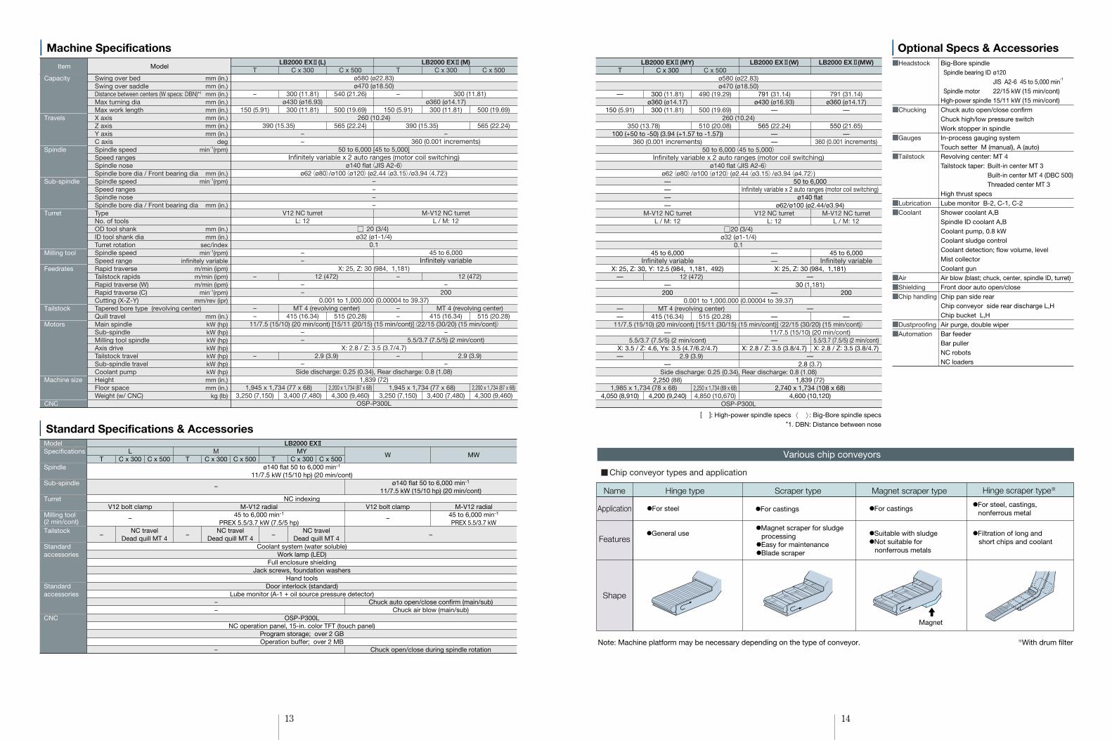
Machine Specifications
Capacity
Travels
Spindle
Sub-spindle
Turret
Milling tool
Feedrates
Tailstock
Motors
Machine size
CNC
Swing over bedSwing over saddleDistance between centers (W specs: DBN)*1
Max turning diaMax work lengthX axisZ axisY axisC axisSpindle speedSpeed rangesSpindle noseSpindle bore dia / Front bearing diaSpindle speedSpeed rangesSpindle noseSpindle bore dia / Front bearing diaTypeNo. of toolsOD tool shankID tool shank diaTurret rotationSpindle speedSpeed rangeRapid traverseTailstock rapidsRapid traverse (W)Rapid traverse (C)Cutting (X-Z-Y)Tapered bore type (revolving center)Quill travelMain spindleSub-spindleMilling tool spindleAxis driveTailstock travelSub-spindle travelCoolant pumpHeightFloor spaceWeight (w/ CNC)
ModelItemT
–
150 (5.91)
–
––
–
3,250 (7,150)
LB2000 EX (L)
ø430 (ø16.93)
––
V12 NC turretL: 12
––
––
––
–
C x 500
540 (21.26)
500 (19.69)
565 (22.24)
515 (20.28)
2,200 x 1,734 (87 x 68)4,300 (9,460)
C x 300
300 (11.81)
300 (11.81)
415 (16.34)
3,400 (7,480)
ø580 (ø22.83)ø470 (ø18.50)
260 (10.24)
50 to 6,000 [45 to 5,000]Infinitely variable x 2 auto ranges (motor coil switching)
ø140 flat <JIS A2-6>ø62 <ø80> /ø100 <ø120> (ø2.44 <ø3.15> /ø3.94 <4.72>)
––––
20 (3/4)ø32 (ø1-1/4)
0.1
X: 25, Z: 30 (984, 1,181)
0.001 to 1,000.000 (0.00004 to 39.37)
11/7.5 (15/10) (20 min/cont) [15/11 (20/15) (15 min/cont)] <22/15 (30/20) (15 min/cont)>
X: 2.8 / Z: 3.5 (3.7/4.7)
Side discharge: 0.25 (0.34), Rear discharge: 0.8 (1.08)1,839 (72)
OSP-P300L
390 (15.35)
1,945 x 1,734 (77 x 68)
12 (472)
MT 4 (revolving center)
2.9 (3.9)
12 (472)
MT 4 (revolving center)
2.9 (3.9)
390 (15.35)
1,945 x 1,734 (77 x 68)
T
–
150 (5.91)
–
––
–
3,250 (7,150)
LB2000 EX (M)
ø360 (ø14.17)
–360 (0.001 increments)
M-V12 NC turretL / M: 12
45 to 6,000Infinitely variable
–200
–5.5/3.7 (7.5/5) (2 min/cont)
–
C x 500
500 (19.69)
565 (22.24)
515 (20.28)
2,200 x 1,734 (87 x 68)4,300 (9,460)
C x 300
300 (11.81)
415 (16.34)
3,400 (7,480)
300 (11.81)
mm (in.)mm (in.)mm (in.)mm (in.)mm (in.)mm (in.)mm (in.)mm (in.)
degmin-1(rpm)
mm (in.)min-1(rpm)
mm (in.)
mm (in.)mm (in.)
sec/indexmin-1(rpm)
infinitely variablem/min (ipm)m/min (ipm)m/min (ipm)
min-1(rpm)mm/rev (ipr)
mm (in.)kW (hp)kW (hp)kW (hp)kW (hp)kW (hp)kW (hp)kW (hp)mm (in.)mm (in.)
kg (lb)
Standard Specifications & Accessories ModelSpecifications
Spindle
Sub-spindle
Turret
Milling tool(2 min/cont)Tailstock
Standardaccessories
Standardaccessories
CNC
T
–
T
–
C x 300 C x 500W
V12 bolt clamp
–
MW
M-V12 radial45 to 6,000 min-1
PREX 5.5/3.7 kW
ø140 flat 50 to 6,000 min-1
11/7.5 kW (15/10 hp) (20 min/cont)
–
Chuck auto open/close confirm (main/sub)Chuck air blow (main/sub)
Chuck open/close during spindle rotation
LC x 300
V12 bolt clamp
C x 500M
–
––
–
MY
ø140 flat 50 to 6,000 min-1
11/7.5 kW (15/10 hp) (20 min/cont)
NC indexing
Coolant system (water soluble)Work lamp (LED)
Full enclosure shieldingJack screws, foundation washers
Hand toolsDoor interlock (standard)
Lube monitor (A-1 + oil source pressure detector)
OSP-P300LNC operation panel, 15-in. color TFT (touch panel)
Program storage; over 2 GBOperation buffer; over 2 MB
NC travelDead quill MT 4
M-V12 radial45 to 6,000 min-1
PREX 5.5/3.7 kW (7.5/5 hp)NC travel
Dead quill MT 4NC travel
Dead quill MT 4
T
–
C x 300 C x 500
–
LB2000 EX

15 16
Tooling System
LB2000 EX (L)
ID Turning OD Turning
Chucking Kit Chuck table
Chuck
Drive
E Kit : *2Hollow 6 in.B-206-01SS1243
BB Kit : *1Hollow 6 in.B-206-01SS1452
D Kit : *3Hollow 8 in.B-208-01SS1452
LB2000 EX (MW)
LB2000 EX (W)
LB2000 EX (M/MY)Mill/Drill
Turning
Mill/Drill
Turning
ID TurningOD Turning
� Commercially available items
* Select an ID oil-hole toolholder base (optional) for oil-hole drills and boring bars. (LB200 same tooling)
� Boring bar shank diameters
ø 8ø10ø12
ø16ø20ø25
ø5/16ø3/8ø1/2
ø5/8ø3/4ø1
Boring bar sleevesBS 8-H32BS 10-H32BS 12-H32
BS 16-H32BS 20-H32BS 25-H32
� DrillMT 1MT 2MT 3
Drill sleeve DS MT 1-H32DS MT 2-H32DS MT 3-H32
ID-H32*� Boring bar ø32(ø1-1/4)
V12 turret(360 across flats)
(14.17)
OD-
� OD tool shank20 x 20
(3/4 x 3/4)
OD-
� Boring barø20 (ø3/4)
� Boring bar ø32 (ø1-1/4)
Boring bar sleeves
Boring bar sleevesDS MT 1-H32DS MT 2-H32DS MT 3-H32
Drill sleeves
BS 8-H20BS 10-H20BS 12-H20BS 16-H20
BS 8-H32BS 10-H32BS 12-H32
BS 16-H32BS 20-H32BS 25-H32
ID- -S(H20)(ID: main) (OD: sub)
ID- -S(H20)(ID: main, sub)
ID- -S(H20)(ID: main, sub)
ID- -S(H32)(main)
V12 turret(360 across flats)
(14.17)
� Commercially available items
* Select an ID oil-hole toolholder base (optional)for oil-hole drills and boring bars.(LB200-W same tooling)
OD- -S(OD, grooving: main)
OD- -S(End: main, sub)
OD- -S(OD: main, sub)
OD- -S(OD: main, sub)
OD- -SStopper (main) OD (sub)
Drill sleeves DS MT 1-H32DS MT 2-H32DS MT 3-H32
Boring bar sleevesBS 10-H32BS 12-H32BS 16-H32
BS 20-H32BS 25-H32
� Boring bar ø32
OD-
OD-
ID-H32
V12 turret(340 across flats)
(13.39)
Axial mill/drill unit
Dummy holder
Radial mill/drill unit
� Colletsø4, 5, 7, 8, 11, 12, 13, 14,
15, 16, 17, 18, 19, 20
� Commercially available items
* Select an ID oil-hole toolholder base (optional)for oil-hole drills and boring bars.(Not compatible with LB200-M)
Drill sleevesDS MT 1-H32DS MT 2-H32DS MT 3-H32
Boring bar sleevesBS 10-H32BS 12-H32BS 16-H32
BS 20-H32BS 25-H32
� Boring bar ø32 (ø1-1/4)
ID-H32-S
ID-H32-S (W)
OD- -S (W)
OD- -S (W)
main
sub
V12 turret(340 across flats)
(13.39)
Axial mill/drill unit
� Colletsø4, 5, 7, 8, 11, 12, 13, 14,
15, 16, 17, 18, 19, 20
(back application possible)
Dummy holder
Radial mill/drill unit
* Select an ID oil-hole toolholder base (optional)for oil-hole drills and boring bars.(Not compatible with LB200-M)
� Commercially available items
ModelSpecifications
Chuck
DriveSub-spindle chuckSup-spindle driveSoft jaws, ASoft jaws, BHard jawsOD-IOD-IIOD-I-SOD-II-SOD-III-SOD-IV-SID-H32ID-I-S (H32)ID-II-S (H20)ID-III-S (H20)ID-H32-S (main)ID-H32-S (sub)DS MT No.1-H32DS MT No.2-H32DS MT No.3-H32BS 8-H32BS 10-H32BS 12-H32BS 16-H32BS 20-H32BS 25-H32BS 12-H20BS 16-H20Axial mill/drill unitRadial mill/drill unitDummy holderRevolving center*MTNo.4
LB2000 EX
Std ChuckingKit
Solid 6 in.N-06
Y1020
LStd Tooling
Kit
42
6
1
22
ChuckingKit
BB kit : *1E kit : *2 D kit : *3
53163
6
11
222222
MChucking
KitBB kit : *1E kit : *2 D kit : *3
53162
3
1
22222
2231
Std ChuckingKit
Solid 6 in.N-06
Y1020
WSub Chucking
Kit
Hollow 6 in. B-206SS1243
Std ToolingKit
2221
421
1
22
12
MWTooling
Kit
31
32
222
223
Chucking Kit / Tooling Kit
MY kit specs not available.* MT 4; not available for T model specifications
*1, *2, *3 cross-referenced for these two tables.

260st.100170
ø580ø200
ø225
ø180
ø225 280
ø32
ø235
ø220
ø265
705
75 ø210
ø195
ø245
75 25
80
27
27
ø240
70
260st.90
75
170
ø570ø230
ø175
ø210
ø195
ø220
ø254
ø235
ø235ø220
ø20
ø20
280 70
705
75
25
6765
132
70
260st.130170
50 55
ø580
7525
8014
7
67
27
ø32
ø185
ø215
ø185ø220
ø220
ø180
ø220
ø32
70755 70
2555
3085
11525 90
ø32
ø200
ø235
ø170
ø205
ø230
ø185
100
25100
ID-H32
ID-H32
ID-H32
4.6
9.2
Max. swing dia ø634634
Max. swing dia ø634 Max turning dia ø360
Spindlecenter
6
3.5
5853.5
16.8
12.2
Max turning dia ø360
Spindlecenter
Max. swing dia
Max. swing dia ø604604
Max. swing dia ø604
Max turning dia ø360
Max. swing dia ø634
Max. swing dia ø634
4.6
9.2
3.5 6
Axial mill/drill unit
Axial mill/drill unit
Axial mill/drill unit
Radial mill/drill unit
Radial mill/drill unit
OD-I
OD-II
OD-II
OD-I
OD-II
OD-I-S
Spindlecenter
Max turning dia ø430
ID-H32
OD-I
OD-II 260st.
260 st.
OD-I-S
OD-III-S
ID-III-S (H20)
Spindle centerSpindle center
Max
turn
ing
dia
ø430
ID-II-S (H32)
OD-II-S
OD-V-S
ID-IV-S (H20)ID-II-S (H20)
Max
. swing
dia
Max
. swing
dia
ø634
634
Max
. swing
dia
ø634
Max turning dia ø430
Max
. swing
dia
ø634
Max
. swing
dia
ø634
Spindle center
Max
turn
ing
dia
ø430
155 105
420180 85
ø220
ø210
ø210
ø32
ø240
ø200
ø230
65
6035
25
80
ø580
60
60
ø210
ø210ø2
0
ø230
ø210ø2
20
ø200
3446
60
17 18
LB2000 EX (W)
LB2000 EX (M)
LB2000 EX (MY)
LB2000 EX (MW)
LB2000 EX (L)
Tool Interference Drawings
ø170
ø170
420180
25
25215 45
ø180ø180
25 4020
6
40
25
ø32
ID-H32-S
OD-I ID-H32
OD-I ID-H32
OD-I Axial mill/drill unit
OD-I Axial mill/drill unit
Working Ranges
Tailstock retract limit191
MA
X42
0(M
IN16
0)
MA
X42
0(M
IN16
0)
MA
X45
0(M
IN19
0)
MA
X45
0(M
IN19
0)
MA
X42
0(M
IN16
0)
MA
X42
0(M
IN16
0)
415Tailstock travel
Turret rotation center Turret rotation center
390 (Z-axis travel)
X-axis travel
765
ø70
4254830
1052976
5
177
11120
283703
134256177
52 6210
200
6026
0
220
180
1525
205
180
764
25
425390 (Z-axis travel)
X-axis travel
4831
1052976
5262
215
260
45
177(390)
703
415Tailstock travel171
282111
20
Tailstock retract limit191
64.2 20143.8
467.1 20860
Tailstock retract limit183.2
97.9842
222
155
197
565 (Z-axis travel)63848
69
10576 29
25
198
4 76
515 (Tailstock travel)
260
(X-a
xis
trav
el)
62
565 (Z-axis travel)
515 (Tailstock travel)
638 7648
260
(X-a
xis
trav
el)
200
60
68 510576 29
70.2 205
143.8183.2
220
180
60
2515
421 144 209842
Tailstock retract limit
60
3010576 29
X-axis travel
390 (Z-axis travel)
446
177214
703176
415 (Tailstock travel)177
5
283111
20 Tailstock retract limit191
ø70
52 62
2575
170
270
125 (
Tool
length
) 215
100
260 18
080
48
10
446390 (Z-axis travel)
X-axis travel10576 29
48
43 13100
177(390)
703
415 (Tailstock travel)202
313111
20
Tailstock retract limit191
6252
240
170
70
260 21
050
Same with or w/o revolving center and release nut
210
50
60
95.2 20183.2 143.8
491 74 239842 60
1343659 10048
3810576 29 24
0
170
70
260
(X-a
xis
trav
el)
180
80
60 74
659 1004868 5 21
10576 29 27
0 170
7525
70.2 205
143.8183.2361 204 209
842 60
260
(X-a
xis
trav
el)
Turret rotation center
Turret rotation center
MA
X45
0(M
IN19
0)
565 (Z-axis travel)
515 (Tailstock travel)Tailstock retract limit
125 (
Tool
length
)
Turret rotation center
MA
X45
0(M
IN19
0)
565 (Z-axis travel)
515 (Tailstock travel)Tailstock retract limit
Turret rotation center
Turret rotation center
Turret rotation center
LB2000 EX (L) ×300
LB2000 EX (L) ×500
LB2000 EX (M) ×300
LB2000 EX (M) ×500

19 20
550 (Z-axis travel)
791606
1052976
48100
5 21152
5
26 59
231
29 76
30 152120
137550 (Z-axis travel)
4135976
14510
5 (M
ax su
b to
l leng
th)
ø169
2575
170
270
180
260
(X-a
xis
trav
el)
80
595 (Sub-spindle st.)
Sub-spindleretract limit
285 Cross slide width
10576 29
48
550 (Z-axis travel)606
791
156 56
100
56 156
231 285 Cross slide width
6012 3
29 76
2976595 (Sub-spindle st.)
550 (Z-axis travel)413137
120212
Sub-spindleretract limit
145
7017
0
5021
026
0 (X
-axi
s tra
vel)
240
212
565 (Z-axis travel)
X-axis travel
63879148
105
76 29
148
76
714 5
44 31 9860
5
ø20
42
7629
11376
252595 (Sub-spindle st.)
3134469120
226
180
4634
15
140
145
Sub-spindleretract limit
260
194
160
100
66
285 Cross slide width
565 (Z-axis travel)
X-axis travel
105
48
76 29
638791
76
805
4
143 285 Cross slide width
42
7629
6876
313595 (Sub-spindle st.)
25268 90120
260 15
510
5
89.5
2560
180
265
140
145
Sub-spindleretract limit
ø169
260 17
090
280
8011
035
3429
5 121
606
10576
70
296 X-axis travel
510 (Z-axis travel)
841289.3
182.2220.7 261
5
143.8122.2
60
515 (Tailstock travel) Tailstockretract limit
170
100
260 21
050
X-axis travel
60648
10576
40
29
510 (Z-axis travel)100
158
240
170
70
842183.2 143.8
292488 22
60515 (Tailstock travel)
X-axis travel
260 21
050
170
7024
0
398 1004856350 (Z-axis travel)
105876 29
361350177 191111
703
415 (Tailstock travel)20 Tailstock retract limit
260 18
080
170
100
270
8025
3429
398 100
121
48
10576 29
522
331173177177
225191111
703
X-axis travel
350 (Z-axis travel)
415 (Tailstock travel)20
5Tailstock retract limit
MA
X45
0(M
IN19
0)
Turret rotation center
MA
X45
0(M
IN19
0)
Turret rotation center
Tailstockretract limit
MA
X45
0(M
IN19
0)
Turret rotation centerM
AX
450
(MIN
190)
Turret rotation center
MA
X42
0(M
IN16
0)
Turret rotation center
MA
X42
0(M
IN16
0)
Turret rotation center
MA
X45
0(M
IN19
0)
Turret rotation center
MA
X45
0(M
IN19
0)
Turret rotation center
OD-I Axial mill/drill unit
OD-I Axial mill/drill unit
OD-IV-S ID-III-S
OD-I Axial mill/drill unit
LB2000 EX (MY) ×300
LB2000 EX (MY) ×500
LB2000 EX (W)
LB2000 EX (MW)
Floor Space
With a mere 3.2 m2 (34 ft2) required for installation, workpieces of up to ø430 x 300 mm (16.93 x 11.81 in.) can be accommodated. This enables maximum use of limited factory space.
Small machine footprint of 3.2 m2 for effective use of plant floor space.
Photo includes some optional specifications.1,855mm (73 in.)
1,734mm (68 in.)
Energy-savings from PREX motorPREX motor developed by Okuma eliminates rotor winding and achieves small size and efficiency.High output, low heat generation spindle drive system is used.
�Energy efficiency 5% increase �Energy efficiency 10% decrease
In environments with normal temperature changes, machining accuracies equivalent to those in
temperature-controlled rooms are achieved.
As long as the operator is comfortable, there is no need for air conditioning to ensure accuracy.
Environmental economic benefits of Okuma’s Thermo-Friendly Concept
�Uses PREX motor·Energy-saving control during
no-load turning
·Lightweight, low inertia, etc.
�High-performance single CPU configuration
�Energy savings from simple design
�Energy-saving display device
Energy-saving servo, NC units
�Power-saving functionPeripheral device power shutoff after completion of automatic operation
·Spindle cooler, etc.
Energy-saving function
�Amount of energy consumed for temperature-controlled room
per year Savings of approximately 135,000 kWh Prevents CO2 emissions equivalent to about 7,500 beech trees
(compared with previous model) (compared with previous model)
*1. Calculations are examples only, and may differ from actual circumstances. Temperature-controlled room capacity: 10 m x 10 m x H3 m ±2°C *2. Monozukuri: Making things—better than ever
Thermo-Friendly Concept
Energy-saving function Energy-saving technology
Ecology & EconomyMachines and technology to achieve eco-friendly "monozukuri" *2
(*1)

21 22
Deep hole synchro tapping Real 3-D simulation (Optional)
Part shape
Hi-tech Okuma mechatronics for advancedmachining applications
� �
� Easy programming of machining know-how � Live-performance machining
� Part program create
� Advanced run
Actual speed
Sp
ind
le s
pee
d
Commanded speed
Time
410
ø23
L/D = 18 is machined without steady
Spindle override change
Chatter eliminatedChatter occursChatter eliminated from next cut
estr
Dep
th o
f cut
Am
ount
of w
ithd
raw
al
Bottomface positionface position
Processedit
Solid view
Continuous run Mid-cycle start (finishing repeated)
Individual run(machining repeated with this tool only)
Reduce machining chatter Good threads from the first pieceFeed axis perfectly synchronized with changing spindle speeds.Thread pitch accuracy is maintained even if the spindle speedchanges during threading. Cutting conditions without chatter canbe found by using spindle override during threading.As a result, you get good quality threads from the first piece.
Holds down machining chatter as spindle speed is periodicallychanged and resonance points change, when cutting large,thin workpieces or small-diameter, long workpieces.
Cutting is divided into multiple cuts by simply designating depth ofcut, amount of relief, and amount of withdrawal, and tool damagefrom chip clogging is prevented. In addition, if overload is detectedduring synchronized tapping, machine returns to machining startpoint with synchronized feed and stops with alarm.
Returns to machining start point when totaldepth of cut reaches amount of withdrawal.
Am
ount
of r
elie
f
In all operating modes (auto, MDI, manual, etc), the cuttingconditions are displayed in real time. Switching betweensolids, section views, transparent models, and performingmachining simulation (dry runs with the machine locked)lets you check part program accuracy.
Autoprocessdecide
Machining process
Advancedrun
Part programcreate
Part program
N0100 G97 S413 M41 M03 M08N0101 G00 X108 Z105.2 T010101N0102 G96 S140N0103 G85 N0104 D8 F0.35 M85N0104 G83N0105 G01 X50.4 Z100N0106 X100 :
After simple cutting data inputs (interactively), the required machining processes are determined and a part program is created(automatically).
To run the machine directly from the interactive part program screen.When a problem is detected it can be quickly corrected and checked, speeding up first part machining.
Directly change cutting conditions foreach process with this process sheet
Tables make it easy to make mid-cycle orindividual process starts
Harmonic spindle speed control (Optional) Interactive operations Advanced One-Touch IGF-L (Optional)Variable spindle speed threading (Optional)

23 24
LB2000 EX (L / M) Specifications✕500 LB2000 EX (MY) Specifications✕500
Spindle fan
Hydraulic unit
1,19
470
454
0
500
Space for sidetank removal
NC
(585
)
910 1,290
64272063
1,700Space for rear chipconveyor removal
168 (336)
Chip conveyor(rear discharge)(option)
Chip bucket(option)
700
(1,0
00)
865
(1,3
63)1,
839
1,77
069
1,05
072
0
1,734
2,599 (2,999)
414
250
1,320
865 (1,265)
615 (1,015)
697 (929)
600(800)
V12 turret Operation panel TailstockChip conveyor(side discharge)(option)
Chip bucket(option)Lube tank
500
2,200
20
53
3,160 (3,650)
600(800)
2,290
38 (274)
70 (1
,000
0)
891
(1,4
35)
Maintenancespace
Headstock
Hyd chuckpressure valve
Coolant pump (side)
870 (1,360)
960 (1,450)
922 (1,176)
Maintenancespace
Lube tank
TailstockV12 turret
Headstock
Hyd chuckpressure valve
Coolant pump (side)
Operationpanel
600(800)
53
(option)
Chip conveyor(side discharge)
Chip bucket(option)
70 (1
,000
0)
89 (1
,435
1)
3,160 (3,650)
20
500
2,2902,200
38 (274)
960 (1,450)870 (1,360)
922 (1,176)
(option)
Chip conveyor(rear discharge)
Chip bucket(option)
(585
)Space for rear chipconveyor removal
Spindle fan Door open
Hydraulic unit
Coolant pump (rear)
1,05
01,
200
2,25
0
704
540
500
1,19
4
700
(1,0
00)
61(1,0155)
697 (929) 168 (336)865 (1,265)
2,599 (2,999)
1,734
865
(1,3
63)
600(800)
2,250913
720414 1,320
642
63
1,337
1,700
250
Space for sidetank removal
NC
Coolant pump (rear)
Door open
LB2000 EX (L / M) Specifications✕300 LB2000 EX (MY) Specifications✕300
LB2000 EX (W / MW) Specifications
Dimensional Drawings
( ) dimensions for H chip conveyor (High)
Dimensional Drawings
( ) dimensions for H chip conveyor (High)
1,945
1,855 960 (1,450)
600(800)
891
(1,4
35)
700
(1,0
00)
500
Maintenancespace
870 (1,360)
905 (1,158) 55 (292)
Headstock
V12 turret Operation panel
Tailstock
Chip bucket
(option)
Lube tankHyd chuckpressure valve
Coolant pump (side)
90 53
Chip conveyor(side discharge)
(option)
500
414Space for sidetank removal 1,320
1,734
2,599 (2,999)
1,83
91,
770
1,05
072
0
69
Space for rear chipconveyor removal
Chip bucket
Chip conveyor(rear discharge)
(option)
(option)
168 (336)697 (929)
865 (1,265)
600(800)
250615
(1,015)
700
(1,0
00)
865
(1,3
63)
1,700
Spindle fan653 527.6
Door open
Coolant pump (rear)
Hydraulic unit
805
599
1,32
0
540
780
414
1,050
NC
63
Chip bucket(option)
891
(1,4
35)
700
(1,0
00)
Operation panel
V12 turret
Headstock Lube tank
830 (1,320)
905 (1,158)870 (1,360)
55 (292)
Maintenancespace
Tailstock
Hyd chuckpressure valve
Coolant pump (side)
1,985500
13053
1,855 960 (1,450)
1,945
(option)
Chip conveyor(side discharge)
600(800)
Space for sidetank removal
865
(1,3
63)
700
(1,0
00)
Chip bucket(option)
1,734
1,700
2,25
01,
050
1,20
085
1.6
414 1,320
250
2,599 (2,999)865 (1,265)
697 (929) 168 (336)
615(1,015)
500
Space for rear chipconveyor removal
(option)
Chip conveyor(rear discharge)
600(800)
Hydraulic unit
NC
1,32
059
941
478
054
0
653 527.6
Spindle fan
Coolant pump (rear)
805 1,050 130
Door open63
700
(1,0
00)
891
(1,4
35)
Sub-spindleV12 turret
Headstock
100
450
Maintenancespace
2,640 870 (1,360)
922 (1,176) 38 (274)
600
Operationpanel
Lube tankHyd chuckpressure valve
Chip conveyor (side discharge)(sub-spindle)(option)
(option)Chip bucket
90 53
960 (1,450)2,550
3,610 (4,100)
Hyd chuckpressure valve
Coolant pump (side)
1,77
01,
050
700
(1,0
00)
865
(1,3
63)
720
414 1,320 697 (929)
615(1,015)250
1,700Space for rear chipconveyor removal168 (336)
1,7342,599 (2,999)
865 (1,265)
Chip bucket(option)
Chip conveyor(rear discharge)(option)
600(800)
1,012
804
1,32
0 (5
85)
500 714
NC
Spindlecooler
Space for sidetank removal
641.669
100
540
780
1,290 Coolant pump (rear)
Hydraulic unit
Spindle cooler(Sub-spindle)
Door open
414

�
Externalprogramselections
Optional Specifications
A simple function key operation is all it takes to shift a zero offset to either the left or right end of a workpiece. The required zero offset will be calculated automatically based on jaw and workpiece lengths. (when the tool offset is set with reference to the turret tool mounting surface)
Templates like this make it easy to set required jaw shape, tool, and cutting conditions.
Part programming not required to do this.
Easy Operation
OSP-P300L Okuma Sampling Path Control
Operation screen split into four displays
Forming soft jaws Zero offsets
Simultaneous display includes setup work, current position needed in confirming movement in trial machining, NC program, and graphic simulation.
Tool registration
Register data for all of your tools. Since the registered tool data is also used by Okuma auto programming (Advanced One-Touch IGF) and a collision check function (Collision Avoidance System), this screen will complete the entire registering process.
When loading a tool in the machine, simply select it from among the registered tools.ATC manual operation does not require inputting the tool number. Just select the tool from the list and press the function key.
Okuma Control[for Lathes]
� OSP-P300LBasic Specs
Operations
Communications/NetworksHigh speed/accuracy
Turning: X, Z simultaneous 2-axis, Multitasking: X, Z, C simultaneous 3-axisOSP full range absolute position feedback (zero point return not required)8-digit decimal, ±99999.999 to 0.001 mm (±3937.0078 to 0.0001 in.),0.001˚ Decimal:1 µm, 10 µm, 1 mm (0.0001,1 in.) (1˚, 0.01˚, 0.001˚)Override: 0 to 200%Direct spindle speed commands (S4) override 50 to 200%Constant cutting speed, optimum turning speed designateTool selection: 32 sets, tool offset: 32 sets15-inch color display operational panel, touch panelAutomatic diagnostics and display of program, operation, machine, and NC system problemsProgram storage: 2 GB, operation buffer: 2 MBProgram management, edit, multitasking, scheduled programs, fixed cycles, special fixed cycles, tool nose R compensation, M-spindle synchronized tapping,fixed drilling cycles, arithmetic functions, logic statements, trig functions, variables, branch statements, auto programming (LAP4), programming help“Single-mode operation” to complete a series of operationsAdvanced operation panel/graphics facilitate smooth machine controlMDI, manual (rapid traverse, manual cutting feed, pulse handle), load meter, operations help, alarm help, sequence, return, manual interrupt & auto return, threading slide hold, data I/O, chuck open/close during spindle rotation, spindle orientation (electric)Machining Management: machining results, machine utilization, fault data compile & report, external outputUSB ports, Ethernet, RS232C interface (1 channel)Hi-G control
ControlPosition feedbackMin / Max inputs
FeedSpindle control
Tool compensationDisplaySelf-diagnosticsProgram capacityPrograming
Easy Operation
MachineoperationsMacMan
Standard Specifications
3D
E D E D E D E D
OT-IGF OTMNMLItem
Kit Specs *1
New Operations
Programming
10 sets
50 sets
100 sets
Tool compensation 64 sets
Tool compensation 96 sets
Tool compensation 200 sets
Tool compensation 999 sets
Work coor-dinate systemselect
Tool compen-sation(Std: 32 sets)
Advanced One-Touch IGF-L *2
Advanced One-Touch IGF-L Multitasking *2
Circular threading
Program notes
User task 2 I/O variables, 8 ea
Common variables 1,000 sets (Std: 200 sets)
Thread matching (spindle orientation required)
Threading slide hold (G34, G35)
Variable spindle speed threading (VSST)
Inverse time feed
Spindle synchronized tapping (rigid tapping)
Helical cutting (within 360 degrees)
Real 3-D simulation
Cycle time over check
Load monitor (spindle, feed axis)
Load monitor no-load detection (load monitor ordered)
Tool life management
Tool life warning
Operation end buzzer
Chucking miss detection
NC operation monitor (counter, totaling)
NC work counter (stops at full count with alarm)
Status indicator (triple lamp) Type C [Type A, Type B]
In-process work gauging
Z-axis automatic zero offset by touch sensor
C-axis automatic zero offset by touch sensor
Gauge data output
Post-processwork gauginginterface
Touch setter [M, A]
Monitoring
Count only
Cycle stop
Start disabled
Power ON
Spindle rotation
NC operating
Milling machinespecs
Coordinate convert
Profile generate
Flat turning
3-dimensional coordinate conversion
Work counters
Hour meters
Measuring
File output
Set levels (5-level, 7-level)
BCD
RS-232-C (dedicated channel)
Included in machine specs
Included in machine specs
Included in machine specs
ItemKit Specs *1 OT-IGF OTMNML 3D
DE D E D E DE
External Input/Output and Communication Functions
Automation/Untended Operation
High-Speed/High-Accuracy Functions
Other Functions
Additional RS-232-C channel
2 channels (Std 1 channel)
DNC link
USB (additional)
Auto power shutoff MO2, alarm
Warmup function (by calendar timer)
Tool retract cycle
Okuma loader (OGL) interface
Third party robot
and loader
interface *3
Bar feeders
Cycle timereduction *3
1/10 µm control *3
Pitch error compensation
AbsoScale detection *3
Hi-Cut Pro
Super-NURBS
Collision Avoidance System (CAS)
One-Touch Spreadsheet
Machining Navi L-g
Harmonic spindle speed control (HSSC)
Spindle dead-slow cutting
Spindle speed setting
Spindle S command 0.1 min-1
Manual cutting feed
Spindle power peak cutting
Short circuit breaker
External M signals [2 sets, 4 sets, 8 sets, ( )]
Edit interlock
OSP-VPS (Virus Protection System)
DNC-T3
DNC-C/Ethernet
DNC-DT
2 additional ports possible
A (pushbutton) 8 types
B (rotary switch) 8 types
C (digital switch) BCD, 2-digit
C2 (external input) BCD, 4-digit
Type B (machine)
Type C (robot and loader)
Type D
Type E
Bar feeder
Interface only
Operation time reduction
Chuck open/close during spindle rotation
Tailstock advance/retract during spindle rotation
Linear axis
Linear axis + rotary axis
Included in machine specs
Including loader specs
*1. NML: Normal, 3D: Real 3D simulation, OT-IGF: One-Touch IGF, OTM: One-Touch M
E: Economy, D: Deluxe
*2. Real 3-D Simulation included
*3. Engineering discussions required.
Note: Triangle items for M function (milling tool) machines only.
25 26
This product is subject to the Japanese government Foreign Exchange and Foreign Trade Control Act with regard to security controlled items; whereby Okuma Corporation should be notified prior to its shipment to another country.
, OGUCHI-CHO, NIWA-GUN, AICHI 480-0193, JAPAN • TEL (0587) 95-7825 • FAX (0587) 95-6074
To protect your factory and equipment from fire and assure continued safe operation, observe the following fire safety precautions whenever you operate machinery. Whenever possible, avoid the use of oil-based coolants for cutting operations. Sparks caused by hot chips, tool friction, and grinding can cause fires. Always observe the following safety measures to ensure safe operation when machining flammable materials or when performing dry machining.
Before machining any material designated by law as a flammable substance, e.g., plastic, rubber, wood, acquaint yourself with the special characteristics of the material in terms of fire prevention, and observe the precautions given in (2) above to ensure safe operation. Example: When machining magnesium, there is a danger that magnesium chips and water-soluble coolants will react to produce hydrogen gas, resulting in an explosive fire if any chip should ignite.
Dry machining is a fire hazard because workpieces, tools, and chips are not cooled. To ensure safe operation, do not place any flammable objects near the machine and do not allow chips to over accumulate. In addition, be sure to check cutting tools to make sure of their service life and the condition of the tool edge, and observe the precautions regarding oil-based coolants given in (2) above.
(1) Use nonflammable cutting fluid coolant. (2) When the use of an oil-based coolant is unavoidable:
Before you begin machining, check cutting tools to make sure of their service life and the condition of the tool edge, and choose cutting conditions that will not cause a fire. Periodically clean the coolant filter to maintain sufficient coolant discharge, and frequently verify that coolant is discharging normally. Take measures to control the outbreak of fire: Place a fire extinguisher near the machine, have an operator constantly monitor operation, and install an automatic fire extinguishing system. Do not place flammable materials near the machine.Do not allow chips to over accumulate. Periodically clean the inside of the machine and the area surrounding it.Check that the machine is operating normally. Never run the machine unattended. Since an automatic fire extinguishing system and other peripherals are needed for grinding operations, please let us know as soon as possible if you plan to perform such operations.
Fire Safety Precautions
1. Oil-based coolant
2. Precautions regarding machining of potentially flammable materials
3. Dry machining
•
•
•
•
•
•
•
•
•
When using O
kuma p
roducts, alw
ays read the safety p
recautionsm
entioned in the instruction m
anual and attached
to the prod
uct.
� The sp
ecifications, illustrations, and d
escriptions in this b
rochure vary in different m
arkets and
are subject to change w
ithout notice.P
ub N
o. SP
AC
E TU
RN
LB2000 E
X -E
-(11a)-300 (Feb 2014)
1-Sad
dle C
NC
Lathe