Embed Size (px)
DESCRIPTION
r
Citation preview
Transonic and supersonic ground effect aerodynamics
G. Doig n
School of Mechanical and Manufacturing Engineering, University of New South Wales, Sydney, Australia
a r t i c l e i n f o
Article history:Received 3 February 2014Accepted 14 February 2014Available online 31 March 2014
Keywords:Ground effectTransonicSupersonicCFDWind tunnelShock reflection
a b s t r a c t
A review of recent and historical work in the field of transonic and supersonic ground effectaerodynamics has been conducted, focussing on applied research on wings and aircraft, present andfuture ground transportation, projectiles, rocket sleds and other related bodies which travel in closeground proximity in the compressible regime. Methods for ground testing are described and evaluated,noting that wind tunnel testing is best performed with a symmetry model in the absence of a movingground; sled or rail testing is ultimately preferable, though considerably more expensive. Findings arereported on shock-related ground influence on aerodynamic forces and moments in and acceleratingthrough the transonic regime – where force reversals and the early onset of local supersonic flow isprevalent – as well as more predictable behaviours in fully supersonic to hypersonic ground effect flows.
& 2014 Elsevier Ltd. All rights reserved.
Contents
1. Introduction . . . . . . . . . . . . . . . . . . . . . . . . . . . . . . . . . . . . . . . . . . . . . . . . . . . . . . . . . . . . . . . . . . . . . . . . . . . . . . . . . . . . . . . . . . . . . . . . . . . . . . . . . . 11.1. On shock reflection phenomena, in brief . . . . . . . . . . . . . . . . . . . . . . . . . . . . . . . . . . . . . . . . . . . . . . . . . . . . . . . . . . . . . . . . . . . . . . . . . . . . . 3
2. Development of experimental methods . . . . . . . . . . . . . . . . . . . . . . . . . . . . . . . . . . . . . . . . . . . . . . . . . . . . . . . . . . . . . . . . . . . . . . . . . . . . . . . . . . . . 43. High-subsonic and transonic ground effect . . . . . . . . . . . . . . . . . . . . . . . . . . . . . . . . . . . . . . . . . . . . . . . . . . . . . . . . . . . . . . . . . . . . . . . . . . . . . . . . 12
3.1. Automotive and rail/maglev . . . . . . . . . . . . . . . . . . . . . . . . . . . . . . . . . . . . . . . . . . . . . . . . . . . . . . . . . . . . . . . . . . . . . . . . . . . . . . . . . . . . . . 123.2. Aircraft and lifting bodies . . . . . . . . . . . . . . . . . . . . . . . . . . . . . . . . . . . . . . . . . . . . . . . . . . . . . . . . . . . . . . . . . . . . . . . . . . . . . . . . . . . . . . . . 153.3. Projectiles. . . . . . . . . . . . . . . . . . . . . . . . . . . . . . . . . . . . . . . . . . . . . . . . . . . . . . . . . . . . . . . . . . . . . . . . . . . . . . . . . . . . . . . . . . . . . . . . . . . . . 19
4. Supersonic to hypersonic . . . . . . . . . . . . . . . . . . . . . . . . . . . . . . . . . . . . . . . . . . . . . . . . . . . . . . . . . . . . . . . . . . . . . . . . . . . . . . . . . . . . . . . . . . . . . . 204.1. Sled and launch vehicles . . . . . . . . . . . . . . . . . . . . . . . . . . . . . . . . . . . . . . . . . . . . . . . . . . . . . . . . . . . . . . . . . . . . . . . . . . . . . . . . . . . . . . . . . 204.2. Projectiles. . . . . . . . . . . . . . . . . . . . . . . . . . . . . . . . . . . . . . . . . . . . . . . . . . . . . . . . . . . . . . . . . . . . . . . . . . . . . . . . . . . . . . . . . . . . . . . . . . . . . 22
5. Conclusions . . . . . . . . . . . . . . . . . . . . . . . . . . . . . . . . . . . . . . . . . . . . . . . . . . . . . . . . . . . . . . . . . . . . . . . . . . . . . . . . . . . . . . . . . . . . . . . . . . . . . . . . . 24Acknowledgements . . . . . . . . . . . . . . . . . . . . . . . . . . . . . . . . . . . . . . . . . . . . . . . . . . . . . . . . . . . . . . . . . . . . . . . . . . . . . . . . . . . . . . . . . . . . . . . . . . . . . . . 26References . . . . . . . . . . . . . . . . . . . . . . . . . . . . . . . . . . . . . . . . . . . . . . . . . . . . . . . . . . . . . . . . . . . . . . . . . . . . . . . . . . . . . . . . . . . . . . . . . . . . . . . . . . . . . . 26
1. Introduction
As an object passes through a compressible fluid such as air, theaerodynamics of the body are affected by density changes in thefluid around it. These aerodynamic effects are influenced – usuallyexaggerated – by proximity to a ground plane, in particular whenshock waves reflect from the ground to interact with the bodyagain one or more times. Traditionally, most aeronautical groundeffect research (excluding study of vertical take-off and landing
(VTOL)) has concentrated on the properties of wings in nominallyincompressible flows, i.e. at relatively low subsonic Mach numbers.Applications have included aircraft in landing or takeoff modes,aircraft designed specifically to fly in ground effect, or in the case ofinverted wings, high-performance racing vehicles. In these cases,proximity to the ground serves to enhance the lift (or downforce)performance of the wing, and often the overall aerodynamicefficiency as well.
Recent developments in the understanding of the aerodynamicinfluence of compressible ground effects and of shock/groundinteraction for ground effect problems are timely, particularlygiven new or recurring interest in high-speed subsonic (free-stream Mach number, M1Z0.4) wing-in-ground effect (WIG)
Contents lists available at ScienceDirect
journal homepage: www.elsevier.com/locate/paerosci
Progress in Aerospace Sciences
http://dx.doi.org/10.1016/j.paerosci.2014.02.0020376-0421 & 2014 Elsevier Ltd. All rights reserved.
n Tel.: þ61 2 9385 5428.E-mail address: [email protected]
Progress in Aerospace Sciences 69 (2014) 1–28
aircraft [1], magnetic-levitation space vehicle launch systems [2],and high speed rail [3] or tube transport systems. For moreesoteric applications, it has also been speculated that the shockwaves from an extremely low-flying supersonic aircraft couldpotentially be used as a means to suppress large-scale uncon-trolled fires such as forest fires [4,5], or that the use of a sonicboom from a low-flying supersonic jet could be used as a non-explosive weapon to injure or disorient humans as part of amilitary operation [6].
To take aircraft as an example: in an comprehensive review ofWIG aircraft aerodynamics and technology, Rozhdestvensky [1]affirms “it can be stated that little is still known with regard to GE(ground effect) at high subsonic Mach numbers”. By that time, in2006, brief test studies indicated that increased aerodynamicefficiency may be possible for a high aspect ratio wing in groundeffect at high subsonic Mach numbers [7], but other analyticaltreatments suggested the opposite [1]. However, the effects of theformation of shock waves either on a wing upper surface, orbetween the wing and the ground, were rarely considered in anapplied or fundamental context until the most recent decade.
It should be noted that this paper is not concerned withphenomena such as sonic boom interactions with ground objectsor water, or shock focussing effects from altitude, as these do notaffect the aerodynamics of the body from which the wavesoriginate. Similarly, while the case of a high speed subsonic orsupersonic jet impinging on a surface from perpendicular orangled flow is certainly of considerable practical and fundamentalinterest [8], it lies outside the definition of a body travelling over asurface in close proximity that will suffice for the present work.
Ground effect is commonly categorised in terms of the clear-ance being within a few characteristic lengths of the ground planein order for the aerodynamic performance of the body (i.e. anaircraft or vehicle) to be affected. Consider a wing of chord c at aheight of h, for an h/c ratio of less than 5 (for other bodies a more
meaningful characteristic length may be the total length, ordiameter). Above this level, the ground has negligible influence,but at lower clearances the lifting performance of the wing isgradually enhanced with closer ground proximity. Extreme groundeffect may be taken to mean a clearance that is less than 10% of thecharacteristic length of the body. This holds nicely into thetransonic and supersonic domain, however, the ability for a bodyto be non-trivially influenced by a shock reflection from a groundplane at relatively high h/c ratios will later be described for Machnumbers close to 1.
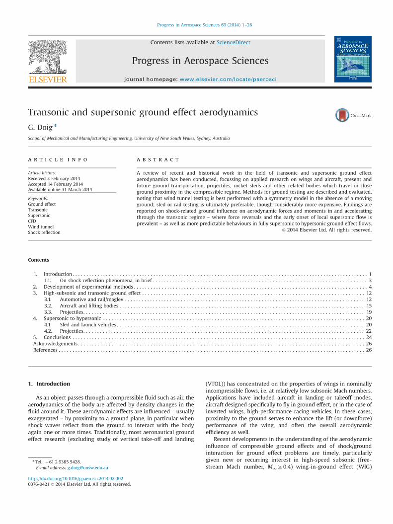
Basic examples of the kinds of flowfields of interest for thisreview are shown in Fig. 1 using the example of an aircraft withrelevant parameters annotated. The schematics are by no means afull survey of the possible flowfields for high speed ground effectscenarios. Fig. 1(i) shows a typical coalescence of waves from asupersonic aircraft to form a sonic boom felt at the ground, whichwould produce a characteristic N-shape pressure wave – withsignificant altitude, the waves cannot reflect back onto the aircraftagain or into its wake, and with such distance the waves are alsorelatively weak. Thus, this flowfield is not considered to be aground effect scenario.
Fig. 1(ii) presents a case where the ground clearance ratio, h/l,may be close to 1, with the Mach number close to 1 as well. In thissituation, local areas of supersonic flow will form and the groundproximity will lead to a ground reflection that may impinge on theaircraft body again, and a ground-related asymmetry in thesupersonic region would occur. A photograph highlighting thiskind of reflection/interaction is presented in Fig. 2. In such a case,it is likely that a small effect on aircraft aerodynamic character-istics would occur. Fig. 1(iii) shows a supersonic case close to Mach1 where oblique, near-inviscid reflection from the ground planemay occur depending on the Mach number and shock angle but itis also possible for the bow shock to bend to the wall andan entirely altered flowfield below the vehicle would establish.
Nomenclature
c chord (m)CA coefficient of axial forceCD coefficient of dragCL coefficient of liftCM coefficient of pitching momentCN coefficient of force normal to the ground planeCP coefficient of pressureCY coefficient of side forceCZ coefficient of side force (projectiles)d diameter (m)D drag force (N)
f frequency (Hz)h height (m)k turbulent kinetic energyl length (m)L lift force (N)M1 freestream Mach numberPo total pressure (Pa)t time (s)u1 freestream velocityα angle of incidenceδ boundary layer thicknessε turbulent dissipation rateω specific dissipation rate
Fig. 1. (i) A high-altitude supersonic vehicle causes a sonic boom at the ground but is not operating in ground effect; (ii) within several height-to-lengths (h/l) at near-sonicspeeds, shocks reflect from the ground (other relevant parameters are shown); (iii) at low-supersonic speeds both normal and oblique reflections may occur; (iv) at fullysupersonic Mach numbers, one or more oblique shocks may interact with the ground and reflect back onto the vehicle when it is in close ground proximity.
G. Doig / Progress in Aerospace Sciences 69 (2014) 1–282

In (iv) a fully supersonic flowfield features multiple obliquereflections and at a certain low ground clearance these waveswould impinge again one or more times on the aircraft, causingsignificant pressure differentials that would strongly influenceaerodynamic performance.
The speeds of the vehicles or freestream flows in questionmake controlled aerodynamic testing in a conventional windtunnel a more difficult matter with regards to ground representa-tion, and so in addition to covering the aerodynamic findingsrelating to bodies at high-subsonic to hypersonic Mach numbers inground effect, the various means of obtaining accurate experi-mental data will be discussed.
The focus is therefore narrowed to the following topics:
(1) which methods of ground representation are available to theexperimentalist and what level of accuracy do they afford?
(2) what effect does ground proximity have on a body's criticalMach number and what are the consequences of this (i.e.early transonic drag rise, buffeting flow, loss of aerodynamicefficiency)?
(3) what influence does the reflection(s) of shock waves from theground plane back onto a body – one or more times – have onthe aerodynamic characteristics of that body?
A comprehensive overview of studies relevant to these ques-tions has not previously been collated, partly because of thediverse range of sources, the sporadic reporting of activity in thefield, and many inconsistencies in terminology across potentiallyuseful works. Some of the research reported in this paper has, untilrelatively recently, not been widely or publicly available despite itbeing conducted in the 1960s and 1970s, due to the classified/military nature of the investigations at the time. Therefore con-siderable space is devoted to describing the findings of that era,and linking them to the most recent developments in the field; thepower of in the 21st century high-performance computing hasfacilitated a greatly expanded knowledge of high speed groundeffect flows through new simulation and re-evaluation of priordata. The review concludes by outlining remaining challenges andopportunities in the field.
1.1. On shock reflection phenomena, in brief
A brief outline is provided here of the kinds of shock/surfaceinteractions which are discussed in the following sections; rele-vant analogies from more fundamental shock wave research areintroduced in the process.
Ernst Mach pioneered studies of shock reflection phenomena,publishing a paper in 1875 on the planar shock-wave reflectionsover straight wedges [10]. He presented two possible waveconfigurations: a regular reflection, and an alternate configurationthat was later named Mach reflection. Fig. 3(i) and (ii) shows basicschematics of oblique reflection configurations: most interest inthe ground effect context are flowfields in which both nominallyinviscid and viscous reflections occur, and thus consideration ofseveral reflection possibilities is useful. The normal shock with alambda (λ) foot boundary layer interaction is a common occur-rence in transonic flows involving wing sections, whereas thesupersonic oblique reflections are often studied more fundamen-tally outside of a direct aeronautical context, but with applications
Fig. 3. (Based on [11]). (i) and (ii) depicting regular shock reflection from a wall with a thin boundary layer and regular reflection from an inviscid wall, respectively, and(iii) and (iv) showing normal shock/boundary layer interaction with a lambda shock, and Mach reflection from an inviscid wall, respectively.
Fig. 2. A US Navy “Blue Angel” demonstration F/A-18 performing a pass at approx.Mach 0.95 (h/l approx. 0.5, mean wing h/c approx. 3). Photo: Matt Niesen (withpermission).
G. Doig / Progress in Aerospace Sciences 69 (2014) 1–28 3

to complex wave interactions on inlets and other aircraft compo-nents. Fig. 3(i) shows regular reflection of an oblique shock wavein a fully supersonic flowfield, where a boundary layer is presenton the reflecting surface. In the thin subsonic region next to thewall, the shock wave cannot be sustained. Within the boundarylayer, the shock and its reflection curve in refraction to normal atthe wall – without a boundary layer (ii), in the simplest case, thereflection angle is the same as that of the incident wave. Fig. 3(iv)shows a scenario in which the Mach number is such that a normalMach stem forms between the incident shock and the ground, anda so-called “triple point” exists at the location where the stemmeets the incident and reflected wave. In this case, a shear layerforms behind the triple point. The Mach number and shock anglesat which the transition from regular to Mach reflection occurs hasbeen the subject of much debate and research due to difficulties inadequately producing the behaviour in wind tunnels [12]. Fig. 3(iii)shows a typical transonic shock boundary layer interaction, wherethe foot of the normal shock provokes some separation of theboundary layer and the “lambda” structure forms to reset the flowdirection to normal after the disruption of the separation bubble.Behind the shock structure the flow is subsonic, and the mainshock is often referred to as the terminating shock. Such waves areprone to oscillation on the surface over a range of high subsonicfreestream Mach numbers, which in an aeronautical context isreferred to as buffet.
At transonic and supersonic Mach numbers, the formation andreflection from the ground of normal and oblique shock waves isoften highly analogous to several other distinct fields of aero-dynamic research, most notably wind tunnel wall interference(where the effect is exclusively undesirable and extremely well-studied [13]), and studies of external stores on aircraft, which havein the past been investigated as simple supersonic streamlinedbodies next to a solid surface [14]. In the latter case, whenexamining the transition from regular to Mach reflection of areflected wave from a store, the assumption of inviscid flow wasdeemed to be a minor inconvenience. Ironically this actuallyserves to more closely approximate the moving ground interac-tions seen for the supersonic projectile in ground effect studiesdescribed in Section 4 of the present work than would have beenthe case if a fully viscous simulation were feasible at the time.Generally, more recent studies of stores consider cavities, complexon-wing configurations and other fully viscous setups that are farless analogous to high speed ground effect.
In 1986 Hornung stated: “the subject of shock reflection is socomplicated that it is necessary to introduce it at some length” [15],and in this spirit the reader of the present work is assumed to befamiliar with the basic aspects of shock waves, and is directed tocomprehensive reviews of shock reflection and boundary layerinteractions available in literature for discussions which do thetopic justice, for instance [15–18]. Further discussion of relevant andrelated material (such as studies involving crossing shock waves) islimited to appropriate points in the forthcoming sections.
2. Development of experimental methods
The most pressing, largely unsolved issue surrounding highspeed ground effect investigations has been how to undertakeexperiments. The following section explores the variety ofapproaches taken and their relative merits. Note that for thepurposes of this paper, a standard has been adopted in figures(where possible) inwhich the flow travels from left to right towardsa stationary object (as is customary in aerodynamics for a wind-tunnel frame of reference), though there are several unavoidableexceptions. For consistency, objects moving through quiescent airare similarly oriented (moving through the image from right to left),
though at first this may seem counter-intuitive. Depending on themost appropriate length scale for a given application, the non-dimensional ground clearance of objects as a ratio of height, h, isgiven as h/d (diameter), h/l (length) or h/c (mean wing chord).
The correct ground boundary condition for all ground effecttesting in a wind tunnel is a moving ground, conventionallyachieved at low subsonic Mach numbers by having a belt travel-ling at the freestream flow velocity [19]. For larger tunnels andmodels this is often approximated more crudely with an elevatedground plane that produces its own boundary layer which, thoughundesirable, can be further minimised with a combination ofsuction and blowing. In the earliest days of ground effect research,it was also shown analytically that a symmetry (or mirror-image)method can be a good approximation for the flowfield [20]. It hassince been discovered that at small ground clearances this canproduce inaccurate data [21–23]. High speed ground effect studiessimilarly require a moving ground, but this is essentially unfea-sible from a mechanical perspective for transonic and supersonicMach numbers.
It is worth visiting some of the findings of studies into groundrepresentation at low subsonic speeds in order to inform thediscussion of their usefulness at higher Mach numbers. In 2002 anumerical study highlighted the difference between stationary, slipwall, symmetry and moving ground boundaries for a lifting NACA4412 aerofoil in ground effect [22]. The symmetry method was seento produce near-identical results to a moving ground simulation upuntil very low ground clearances (h/co0.05), at which point aspurious recirculation ahead of the wing at the ground planeproduced somewhat inaccurate results. An analogy was drawnbetween this observed effect and a vortex pair in a potential flow.The symmetry method did, however, correctly predict a slight lift-loss at the lowest clearances, as was observed for the movingground cases. The CFD was conducted at a freestreamMach numberof 0.32 with the flow treated as incompressible, although at thisMach number and at such low ground clearances, one would expectcompressible effects to be present.
All the problems of aircraft or road vehicle ground effect testingin wind tunnels are also present for experiments on other vehiclessuch as trains. However, the additional complication of flowcompressibility makes Reynolds and Mach scaling extremelydifficult, particularly due to the length of the trains. Studies haveshown between 10% [24] and 30% [25] error in the values of dragcoefficient obtained with scale wind tunnel models and actualtrack-tested trains. The latter study also noted up to 10% differencein lift and drag for wind tunnel studies using a moving ground ascompared to an elevated ground plane. Baker [26] also indicatesthat for a large body, a simulation of the atmospheric boundarylayer should also be present in the wind tunnel in order toapproximate the forces and moments on full-scale trains.
The symmetry method (or mirror-image method) is not commonlyused experimentally for any type of body because of extra cost,complexity and tunnel blockage, although the method was imple-mented for studies by NASA in the 1960s [27]. It was asserted thattests with a symmetry wing setup, with endplates and far from wallinterference, had previously produced results which agreed well withdata for wings actually moving over a ground, though no specificcitation is given. The freestream Mach number was not stated.
As previously mentioned, it can be useful to view high speedground effect as having much in common with wind tunnel wallinterference. In traditional testing, this is unwanted and considerableeffort has been expended over many decades to eliminate theseeffects – one could therefore conceivably find an overwhelmingabundance of historical test records in which transonic tests werecompromised by wall effects and shock reflections, flow choking,resulting model vibrations, etc. In the case of ground effect studies,these effects are inherently part of the flowfields being investigated,
G. Doig / Progress in Aerospace Sciences 69 (2014) 1–284

and warrant specific attention. While it would be tempting to explorethe tunnel wall interference scenario for relatively high groundclearances, it is important to note that the nature of groundrepresentation in the wind tunnel is a signature issue in theinvestigation of transonic and supersonic ground effect problems.Whereas a wind tunnel can develop an extensive boundary layer onthe wall, or have that boundary layer controlled via blowing, suction,bleed to a plenum through holes or perforations, or broader flowfieldcorrections be applied with adaptive walls [13], a static-modelground effect problem calls for a different approach. Were the tunnelboundary layer adequately removed by such conventional means, asupersonic flowfield would produce wave disturbances generated byany slots, holes or perforations in the surface, potentially interferingwith the results. At lower velocities, such disturbances may be evenmore significant for very low ground clearances.
Since the ground representation and flow behaviour in thevicinity is crucial, the development of a suitable wind tunnelmethod is vital, and there exists an increasingly important synergybetween CFD and experimental work in the absence of any oneideal solution [28,29].
Selescu [30] presents the application of a moving belt system to anostensibly trisonic (up to Mach 1.4) intermittent blowdown tunnel, yetconcedes that its operation is limited to a speed of 111 m/s, equivalentto Mach 0.33. Though the mechanism is cleverly synchronised withthe blowdown operation, it would not be necessarily more accurate toany worthwhile extent to implement a moving belt at a speedconsiderably lower than the freestream Mach number.
Recent Japanese development of a high speed jet-driven androcket-driven subsonic test track of 300 m in length was aimed atbeing able to realistically study the behaviour of re-usable spacecraft in early takeoff and landing phases, both subject to consider-able ground effect [31,32]. The maximum speed of the sledarrangement, 200 m s�1 (with a lower suggested operating speedof 150 m s�1), equates to approximately Mach 0.6, placing itwithin the realm of strong compressibility effects between thecraft and the ground, but unlikely to reach the critical Machnumber unless an object were placed in extreme ground effect.As this facility is only recently operational at the time of writing,no detailed test results on aircraft/spacecraft configurations havebeen reported but could be expected to be of great interest interms of ground effect behaviour close to the transonic regime.Despite the obvious considerable expense, the advantage is clearlythat of considerably higher Reynolds numbers than could beobtained even in a sizeable wind tunnel, and the ability to betterstudy acceleration and deceleration phases as no formal, con-trolled, thorough aerodynamic study of these phases has beenreported for any application to the best of the author's knowledge.
Rocket sled facilities for higher speed applications (transonic,supersonic and hypersonic testing) are generally military property,and well established in many countries. In brief, as shown in Fig. 4(i), based on the test work of Strike and Lucas in 1968 [33], thecommon design involves a test vehicle propelled along steel railsby (often multi-stage) rocket motors, guided by a slipper whichwraps around the rail to provide stability and restraint. Therelative merits for performance and stability of various rail gaugesand arrangements are summarised by Minto and others [34] andare not important for the present discussion.
Studies using rocket sleds are almost exclusively related to non-ground effect applications, and the goal of researchers is to place thetest object out of ground effect even though the rocket sled itselfoperates in such conditions. Nevertheless, research related to thedesign and development of such systems offer greater insight for thecurrent topic. Several studies into the evolving design of the Hollomanfacilities in New Mexico were conducted during the 1960s and 1970s[33,35], and while similar sleds exist around the world Holloman isexceptional for the amount of research publicly available on its design
and development. Wind tunnel testing of Fig. 4 sled arrangement wasconducted from M¼1.5 to 4, with an elevated ground plane. Resultswere shown to agree well with subsequent tests with the actual rocketsled, although themargin of error stemming from poor repeatability ofground clearance was considerable. The differences in setup fromwind tunnel to real-life test are shown in Fig. 4 – this also highlightsthe issues faced in the wind tunnel, including interference from theelevated ground leading edge, bow wave/ground BL interaction, and adiffering boundary layer velocity distribution between sled and rail.
In the wind tunnel tests, it was noted that the normal force andpitching characteristics of the model (which was a 1/12th scalecylinder with a conical nose mounted to a rail above the elevatedground) changed sign with increasing Mach number before and
Fig. 4. Schematic of a rocket sled mounted to a rail above the ground for (a) real-world conditions (actual track environment) and (b) a scale model in a wind tunnelusing an elevated ground plane (wind tunnel conditions).Adapted from: [33].
Fig. 5. Wind tunnel tests for a basic rocket sled/slipper/rail arrangement using anelevated ground, indicating likelihood of flow interference from the leading edge ofthe ground plane.Adapted from [33].
G. Doig / Progress in Aerospace Sciences 69 (2014) 1–28 5

after M1¼2. Although not specifically noted in the report of Strikeand Lucas [33], this would most likely have been a function of theway in which the shock from the nose was reflecting from theground plane and interacting again with the model in relation tothe centre of gravity. Rather than consistent trends, the normalforce acting on the model was observed to increase and decreaseconsiderably across the Mach number range tested, indicatingcomplex shock interactions from the simulated rail as well as theelevated ground plane, including downstream influences on themodel sting and force balance due to multiple reflected shocks –
these interactions will be discussed further in Section 5.Strike and Lucas also spent considerable time evaluating the
rail tip geometry for wind tunnel tests [33]. In real sled tests, therail is effectively infinite, but in the wind tunnel the replica mustsit above the elevated ground plane. Therefore the flowfieldincludes not one but two shock/ground interaction problems, asthe upstream tip flow determines how the air meets the sled bodydownstream and is somewhat sensitive as a result.
Fig. 5 indicates the relationshipwhich can exist between the leadingedge of an elevated ground plane and the model. In order to avoidunwanted wave interference on the body being studied, the groundplane must extend upstream by a certain distance that is related toMach number – due to shock angles – and the length of the body. Insome instances this may mean a considerable ground run upstreamwhichmay prove difficult to mount effectively, and which introduces asignificant boundary layer that may almost defeat the purpose.
Sled testing itself – clearly the most preferable option for highspeed ground effect testing were it not for expense and scarcity –
raises two distinct challenges. Firstly the test object (as opposed tothe sled rocket), be it a missile or other payload, should preferably befree of any shock reflection such that its aerodynamics may beassessed as an accurate representation of freeflight, However, placingthe test object either too far forward of the booster rocket andsupport structure, or too high above the rail, could result inprohibitively high moments that would otherwise demand anunfeasibly strong and durable structural requirement (particularlywhen aerothermodynamic loads are exceptionally high). Commonly,for supersonic and hypersonic velocities, the test object is thereforeclose to the ground and closely linked to the main sled apparatus,placing it in close proximity to the guide rail and often the grounditself. Secondly, the design of the actual rocket sled itself, regardless ofthe location and nature of the payload, must take shock reflectionsand interactions into account, both for their effect on the aerodynamicloads of the sled that may lead to complex aeroelastic coupling [36],and their potential for thermal-induced fatigue due to shock impinge-ment on parts of the apparatus [37].
In the case of aeroelastic coupling, some design aspects are ofparticular concern – vibration and excitation of the rail and/or thesled due to shock impingement and transient loads imparted as aresult, and the tendency for the sled and payload to want to liftand pitch due to the build up of high pressure underneath as aconsequence of multiple shock reflections (a defining character-istic of supersonic ground effect flows). The fact that the sled mayaccelerate rapidly through an unstable regime of force and pitch-ing changes exacerbates this issue.
The study of Lamb [36] details the necessity to understand theinfluence of shock reflections back onto the rocket sled test bed ofthe Holloman tracks. Structural failures resulting in payload loss atthe facility due to vibration issues prompted an investigation ofthe potential for shock reflections and interactions with the railand slipper geometries. At the 10 mile Holloman High Speed TestTrack, regularised sled-rail impact frequencies were measured.While some inconsequential frequencies may be attributed tovortex shedding, the reflection and interaction of the bow wavewith the periodic tie-downs holding the track in place andassisting with rigidity and alignment were shown to produceresonance-mode feedback and the assumption of a purely rigidrail was shown to be incorrect. Fig. 6 reproduces an image of theso-called “SM-2” payload close to Mach 4 and has been annotatedwith approximate shock cone shapes representing Mach 1.87 andMach 2.56 conditions; a pressure transducer was located at theposition denoted P and the rail is denoted by the two parallel whitelines – the potential for shock reflection and re-impingement on thepayload from the tie downs, represented by the white box, isevident. Fig. 6 also reproduces the frequency analysis from the test,indicating the shock reflection effect across the entire availablesupersonic Mach number range.
That study concluded by stating that a more holistic approach,integrating consideration of the “interplay among the sled weight,velocity, aerodynamic forces, and the resulting sled-rail impact forceis essential” for allowing more aggressive testing into the hypersonicrange without such a high risk of rail fracture and fatigue. It is likelythat the role of CFD in such studies could be greatly expanded, sincephysical testing is an expensive and risky pursuit – a high resolutionmodel could help identify shock behaviour at a wide range ofMach numbers in a dynamic or quasi-dynamic environment, withLES-based methods able to assist in distinguishing vortex-sheddingfrequencies with reasonable accuracy. A more complex fluid–struc-ture interaction approach would be likely to yield valuable predictiveinsight into rail and sled interactions.
Such a simulation-based path has been started down byresearchers such as Turnbull et al. [38] who more recently
Fig. 6. Holloman rocket sled payload test arrangement at Mach 4.06 with annotated shock angles and reflections for Mach 1.87 and 2.56 as well as rail tie-down locations(white box), and accompanying measured frequencies due to vortex shedding and shock reflection interactions. Reprinted with permission ©The Johns Hopkins UniversityApplied Physics Laboratory.Source: [36].
G. Doig / Progress in Aerospace Sciences 69 (2014) 1–286
reported on the ongoing development of “soft-sled” capabilities atHolloman that are designed to lessen the severe vibration envir-onment. However, it is worth noting that that analysis wasconducted with an Euler solver that would not produce the morecomplex shock/BL interactions which characterise shock reflec-tions back onto the sled geometry, and this may influence thestructural response predicted by simulations. Similarly, a report ondesign software developed specifically for rocket sled develop-ment, as reported by Hegedus et al. [39] promises reasonable,rapid first-pass accuracy with an Euler solver but as observed withthe high-resolution viscous simulations reported by others [40],even a slight miscalculation of shock re-impingement location ona curved forebody could result in a significant over or underestimation of loads for a given Mach number, and surface heatingeffects due to shock/BL interactions into the hypersonic rangewould require more advanced modelling anyway.
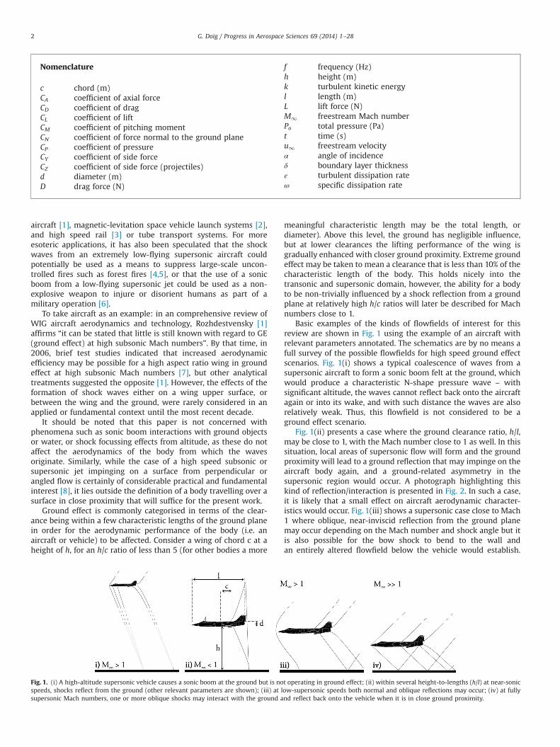
In order to perform a detailed comparison between windtunnel experiments using an elevated ground plane and real-world sled performance, another set of tunnel tests were con-ducted in 1967 across a Mach range simulating acceleration anddeceleration of different sled configurations [41]. Both verticalwedge-based noses, “arrowhead” shapes and combinationsthereof were examined. An example of the results obtained canbe seen in Fig. 7 for the “GNU sled”, which was a relatively thinvertical wedge nose (with a blunted tip), supported by two rocketboosters on either side towards the rear of the 5.2 m body, runningon a dual rail. Different bodies produced markedly different forces,but all featured a strong reaction to the transition from transonic
to supersonic Mach numbers – the causes for such effects will bediscussed further in Section 3. The wind tunnel predictions andthe actual measured force values from the sled are similar in trendbut different in peak magnitude for the forward slipper. At the rearslipper, the predicted forces are more significantly offset –thispoint is after the first series of shock/ground interactions and thenature of that interaction in the wind tunnel, with a ground BL andgeometric simplifications, may be responsible for the discrepan-cies as well as Reynolds number effects [33].
It is also apparent that there are large differences in forcesbetween the front and rear slippers particularly where lift changessign, indicating potentially large swings in pitching behaviour aswell. The peak lifting force occurs in the supersonic regimewhereas transonic flows are generally characterised by downforce– at least up until shock waves form in the accelerating phase –
where a lower surface shock may have been responsible for thefront downforce in particular. Intriguingly, as the sled transitionsback to transonic Mach numbers after 5.5 s of a real sled run, theforces do not follow the same trace as observed in the acceleratingphase, pointing to a strong transient phase in either directionwhere no quasi-steady flow is obtained [42].
This transient phase was also noted in passing by Carriage et al. [43]in examining a small projectile in ground effect at a Mach number of1.2. The schlieren images were resolved enough in time and space todiscern a continuing adjustment period of shock strength and locationfollowing the projectile first passing over the surface. The time taken toreach a nominally steady-state was not quantified but noted as a pointrequiring considerable further investigation as the location of measure-ments on a ground plane would have to be guided by this adjustmentphase. The reflection of the waves and their subsequent interactionwith a spinning boundary layer on the projectile is a unique situationin aerodynamics which is addressed in subsequent sections – for thisparticular problem, the inability to reproduce the high spin rate inscale wind tunnel tests was investigated with CFD and found to be avery minor influence [40].
Korkegi and Briggs [44] note that at very high speeds theaerodynamic lifting forces on a rocket sled may exceed “by far” thedead weight of the apparatus, leading to extensive metal-to-metalcontact on the underside of the rail as the slipper is pulled into it.Again a product of the build up of high pressure underneath thesystem constricted by proximity of the test object to the rail andground, this obviously leads to severe friction in addition toaerodynamic heating. Intriguingly, the slipper itself operates inexceptionally close proximity to the rail in its own “ground effect”,and boundary layer flow behind the local bow shock is forced intothe fluid gap to create a Couette-esque aerodynamic effect. Thepressure in this gap decreases with gap height (analogous toground clearance reduction) rendering the configuration as stati-cally unstable and prone to track-gouging.
To counteract the tendency towards extreme lifting behaviour,canards are commonly attached to the nose-cones of rocket sledforebodies to provide a measure of counteracting downforce, andthese are also routinely attached to the forebodies of similarlyshaped rocket or jet-powered land speed record vehicles such asthe Budweiser Rocket, the Bloodhound SSC, etc.
Predating the modern era of CFD, a handful of land speedrecord cars were designed with the aid of a wind tunnel – themuch-revered Goldenrod streamliner, which held the wheel-driven land speed record from 1965 to 1991 (and a non-supercharged record until 2010), was developed using the CalTech10 ft tunnel with a 1/5th scale model [45]. The tests utilised anelevated ground plane with significant upstream reach and agently contoured leading edge, and the chief aerodynamicist ofthe project reported that the wheels were elevated above theground by the estimated thickness of the boundary layer to chaseextra accuracy. While this may have been partially effective, the
Fig. 7. Rocket sled front and rear slipper loads during acceleration and decelerationphases through Mach 1; comparison of real-world test and interpolated predictionsfrom wind tunnel data.Adapted from [41].
G. Doig / Progress in Aerospace Sciences 69 (2014) 1–28 7

boundary layer responds to the local pressure field and thereforewould not react as a consistent quasi-surface in the vicinity of avehicle. It has also been reported for subsequent studies on wheelaerodynamics, albeit for open rather than enclosed wheels, thatany gap between the bottom of the wheel and the ground mayresult in extremely inaccurate, or even reversed, force predictionsfor that wheel due to the lack of a high pressure spike in thecontact patch region [46].
The electric land speed record vehicle Buckeye Bullet 3 isdescribed by Bork [47] as being subject to extensive CFD develop-ment that in turn builds on wind tunnel work on the BuckeyeBullet 2 at the Penske facility in North Carolina, where a 1/3 scalemodel was tested. That model featured no wheels or undersidedetail; a facet which the CFD later revealed to be significant, withwheels accounting for over 20% of the vehicle drag even whenalmost completely covered, making a compelling case for a closesynergy between CFD and wind tunnel to better understand thelimitations of both. Although the CFD was run for speeds up to500 mph (in the Mach 0.7 vicinity), no mention is made of anysupersonic flow in the study.
The Blue Flame rocket-powered land speed record car – thefirst vehicle explicitly designed and built to be likely to go super-sonic on land – was developed with a 1/25th scale model in theOhio State University transonic wind tunnel with a 1200 by 1200 testsection featuring perforated walls [48]. The researchers indicated aconsideration of the possible benefits of a symmetry model in thetunnel, but in the end pursued an elevated ground for the testprogramme. The ground was pressure-tapped to check for flowseparation on the ground plane. This potential to separate theground boundary layer with a sufficiently strong incident shockwould then produce an induced separation shock and are-attachment shock affecting the body downstream [49]. Thesealtered reflections would influence the accuracy of any resultsobtained, further supporting the case for ground boundary layerminimisation as a percentage of the ground clearance and modelsize.
Detail was not givenwith regards to the design of the leading edgeof the elevated ground. Schlieren images, though difficult to discernfrom, indicate that at the rear of the vehicle in the vicinity of theproposed wings, the boundary layer on the elevated ground occupiedapproximately 33–50% of the vehicle ground clearance [48]. However,this visual appearance is likely to be exaggerated in the image due tothe image's effective integration of the flowfield across the sectionincluding the boundary layer at the ground/window junction. How-ever, the boundary layer would have distorted the pressure and forcereadings taken. Images for Mach 1.1 runs also appear to show tunnelwall interference. Measurements made on the actual vehicle indicatedthat the drag predictions of the wind tunnel model were up to 40%higher [50], and it is likely that this boundary layer interference withthe flow would have been a considerable contributor to this. Theauthors note that “only local separation of the boundary layer on theplate occurred” but it would not be known how realistic this wascompared to the real world, as the wind tunnel boundary layer wouldbe undoubtedly thicker.
To date the only effective synergy between experiments andCFD for a transonic ground effect vehicle has been the Thrust SSCcar, which was the first, and so far only, to set an official supersonicland speed record (M¼1.0175). When testing the concept of theThrust SSC supersonic land speed record car, designers were ableto conduct tests using the Pendine Sands rocket sled facility inWales [51]. The Pendine Sands rocket sled is 1500 m in length witha maximum capability of Mach 3 [52]. The small-scale model waspressure-tapped, as was a specially implemented flat groundsection over which the model passed at a lowest “wheel” clear-ance of 1 mm [53], over 13 runs and speeds of up to 820 mph(367 ms�1). Haddleton describes the high-speed photography of
these 1/25th scale model tests [54] and the use of the imagery toestablish the floor ground clearance, quoted as being 25 mm and13 mm on two occasions. Though difficult to discern due to somemotion blur, shock interaction with the ground is visible. The datawere never published, but the agreement between experimentalresults and CFD conducted at the time was deemed to be excellent[53,51]. However, the CFD, while state-of-the-art in 1992/1993,featured a markedly simplified geometry (including symmetricrear wheels instead of the offset, staggered arrangement used onthe final vehicle), and the fluid was treated as inviscid. Given thatthe boundary layer on the test model would have been consider-able in relation to the model itself, and numerous underbodyshock-boundary layer interactions would have occurred, suchagreement may have been fortuitous to an extent.
Examples of such rocket sled usage to specifically examine highspeed ground effect are exceptionally rare compared to the use ofsmall wind tunnels. The basic premise, problems and potential ofboth symmetry and elevated ground methods in a blowdownsupersonic tunnel are further highlighted by the colour schlierenimages in Fig. 8. The model used for these wind tunnel experi-ments was a simple wedge shape; an extruded two-dimensionalgeometry with a horizontal undersurface. The upper surface was adouble-angle wedge, at 22.61 from the leading edge, reducing to5.11 on the top surface. The experiments were performed in thesupersonic blowdown wind-tunnel of the University of New SouthWales at the Australian Defence Force Academy (ADFA) campus.The facility was fitted in this instance with a Mach 2 liner.Two ground clearances were investigated: 5 mm and 10 mm,which equate to 0.0625 and 0.125 height-to-length (h/l) ratiosrespectively.
The presence of a shock followed by an expansion on the lowerside of the leading edge denotes that the leading edge is not quitea perfect sharp edge, and that the flow structure is still highlythree-dimensional when the object has a low aspect ratio, creatinga shock cone that perpetuates around the entirety of the model.It may be assumed that the leading edge shock from the undersideis extremely weak given the lack of a definite flow-turning surface,although its exact strength is difficult to determine from schlierenalone. One can also see the point at which this cone interacts withthe test section window, due to the way in which schlierenhighlights gradients in planes perpendicular to the viewing angle.From these images it also becomes clear that the potential formodel deflection is problematic as even a slight change in groundclearance can alter the flowfield substantially, as seen in image (c)where the model was sucked towards the ground plane from itsinitial horizontal installation. While this is likely to be more of anissue for an elevated ground case, care must be taken that theground itself is well-aligned with the oncoming flow, and that thesymmetry models are as perfectly symmetrical as possible. Thiscan be difficult even with good manufacturing tolerances andimage (d) shows that a marginal asymmetry in shock patterns canbe caused by slight mis-alignment in the vertical plane too.
Following those initial experiments highlighting many of thepossible issues, the feasibility of using the elevated ground andsymmetry methods for fully supersonic problems was investigatedfurther by Doig et al. in 2008 [40], with a projectile modeldesigned to replicate tests on a spinning projectile (a NATO5.56 mm round) that will be described in more detail in Section 4.The projectile's size allowed close Reynolds-scaling (geometric2.5:1) as well as matching the flight Mach number of 2.4 in thewind tunnel, although the projectile's high spin rate was notdeemed to be practically reproducible. The elevated ground planewas a simple design, very similar to those used for the Hollomanrocket sled tunnel tests [33], that featured a sharp wedge at theleading edge that left the upper surface parallel to the flow. Thesymmetry model consisted of two projectiles stung from the rear
G. Doig / Progress in Aerospace Sciences 69 (2014) 1–288

and held at “ground” clearances of h/d¼0.5 and 0.42. At the latterclearance, on the elevated ground, the boundary layer wasestimated from Schlieren images and analytical calculations tobe over 40% of the clearance space, and as with the double wedgemodel the shock reflection patterns became notably exaggeratedthe further downstream measurements were taken – the firstshock reflection of the elevated ground plane was 3.5% furtherupstream, the second 6%, etc., indicating a propagation of errorswith each reflection.
This would assume that the symmetry method was a goodapproximation of a moving ground, but to make this comparisonthe authors had to rely on RANS CFD of the wind tunnel experi-ments. Having validated with good agreement between predictedand measured pressure distributions around the projectile [40],the CFD indicated that the symmetry and moving ground resultswere essentially identical in terms of projectile surface pressuredistribution and forces, whereas the elevated ground plane offeredthe expected offset and slight diffusion of the reflecting shockwave. No comment was made on additional influence from theground plane leading edge.
The h/d¼0.42 case was highlighted as being of particularinterest as the elevated ground produced a reflected shockimpingement that coincided directly with the expansion regioncaused by the geometric blend from ogival nose section tocylindrical body, whereas the symmetry method predicted animpingement location just downstream, causing a large differencein local CP. Lift force was deemed to be 4% higher for the elevated
ground, with symmetry and moving ground being within 0.1% ofeach other (i.e. within the bounds of numerical error), though itwas acknowledged that having a physical ground plane allowedfor significant instrumentation and visualisation not otherwisepossible. Example comparisons of RANS CFD models of these windtunnel tests, including the h/c¼0.42 test, are presented in Fig. 9.While it is apparent that the symmetry method results are near-identical to the moving ground result in terms of projectilepressures, it is clear that an h/d of 0.2 the ground boundary layerformed on the moving ground is actually influential enough, giventhe small clearance, to produce a different pressure distribution inthe region behind the impingement of the rear lower recompres-sion shock, perhaps even indicating mild separation that is alsopresent in the elevated ground case. However, the elevated groundmis-predicts the shock-impingement CP itself and also exhibits adiffused distribution in the vicinity of shocks on the projectile.
When the symmetry method is used, alignment must be of thehighest precision otherwise the flow will become distorted andend up a poor representation of the moving ground flow – slightmisalignments have been seen to have obvious and detrimentaleffects in some reported studies [55], and thus care must also betaken to perform careful measurements of any deflections in thewind tunnel with wind on.
Doig et al. attempted to extend the study of effectiveness of anelevated ground and symmetry technique to unswept wings in aMach number range from 0.5 to 0.8 [56]. Wind tunnel testing wasconducted in the 0.2 by 0.2 m transonic wind tunnel at the United
Fig. 8. Double wedge model in a Mach 2 blowdown tunnel, indicating shock reflection patterns achieved with an elevated ground plane and symmetry method producing an“imaginary” ground. (For interpretation of the references to colour in this figure caption, the reader is referred to the web version of this paper.)
G. Doig / Progress in Aerospace Sciences 69 (2014) 1–28 9

States Naval Academy and used an RAE2822 wing section of aspectratio 3, featuring a turbulent trip near the leading edge andstaggered chordwise pressure tappings. The authors chose to keepthe porous floor and ceiling closed in order for the tests to beeasily replicable in CFD, however the inconsistent blockage per-centages caused by the two different methods was found to have anon-negligible influence. This led the study to rely more on theRANS modelling as validated against the tunnel experiments thanthe tunnel experiments themselves. Nevertheless, some pertinentconclusions were drawn: For all Mach numbers and groundclearances investigated, the symmetry method provided a super-ior match to results obtained from CFD featuring a moving ground.
Only at clearances approaching an h/c ratio of 0.1 did minordiscrepancies in the pressure distribution close to the leading edgeand suction peak appear. This was partly due to the minorinfluence of the thin ground boundary layer forming on themoving ground but not on the symmetry axis, and also due todiscrepancies emerging as the high gradient region close to thestagnation zone began to merge with the ground and symmetryplane, behaving differently in each case.
Pressure distributions on the wing and ground centre planes inFig. 10 highlight the fact that without significant additional flowacceleration between the wing and the ground (such as thatoccurring at low angles of attack), all methods produce acceptable,close results. If the clearance is low enough that boundary layerthickness becomes an issue, or that local supersonic flow mayform between the wing and ground, then neither method providesa truly accurate prediction of moving ground flow, with thesymmetry method unable to incorporate the slight alteration tothe effective cross-sectional area caused by the boundary layerwhich forms on the moving ground, and the elevated groundgreatly exaggerating this effect.
The elevated ground had a tendency to artificially increase theeffective angle-of-attack of the wing by deflecting more air over
the upper surface. At low ground clearances, the ground boundarylayer served to further constrict the flow between the wing andground such that higher Mach numbers were achieved over bothsurfaces of the wing compared to those obtained with thesymmetry method. Both these effects served to reduce the criticalMach number. It was also noted that the elevated ground approachhas an in-built limitation in that when it reaches its own criticalMach number, the downstream flow would be significantlydisrupted and bear little resemblance to that which would beattained with the symmetry method. Issues of scale were presentas they would be in any wind-tunnel test [57,58], though compli-cated slightly by the relatively large boundary layer compared tothe overall ground clearance compared to supersonic groundeffect cases.
One can appreciate that even a better design of the leadingedge, featuring a contour which avoids the risk of any separation,has two intrinsic limitations. Firstly it will accelerate the flow atthe ground plane to a value which is faster than the freestream.This is particularly problematic if the ground clearance of the testmodel is small, in which case the lower surface could ‘see’ anentirely different oncoming flow than the upper surface. Secondly,introducing significant curvature at the leading edge, even if it isdesigned to settle the flow downstream to a level which would notsignificantly disturb the wing, would still result in the emergenceof a shock wave at a certain Mach number.
Returning once again to aspects of wind tunnel interference forconventional testing, it is possible to find other pertinent insight-ful data relating to the role of a splitter plate (very similar to theelevated ground principle) for transonic testing – commonlyimplemented as a means of negating the side wall boundary layerby introducing what is effectively the same mechanism as theelevated ground discussed here. Tests conducted in the NASALangley Transonic Dynamics Tunnel, reported by Schuster [59],from subsonic to low-supersonic Mach numbers with a side-wall
Fig. 9. Pressure coefficients from a CFD replication of wind tunnel tests for a projectile model at Mach 2.4, comparing ground representation techniques at h/d¼0.42 and 0.2.
G. Doig / Progress in Aerospace Sciences 69 (2014) 1–2810

splitter plate indicate that the flow is relatively free of interferenceeffects until the supercritical stage is reached (between M1¼0.7and 0.8). The shape of the leading edge of the plate, in particular,was found to be a strong determinant in defining the boundary atwhich sonic flow occurred. A shock wave near the leading edge ofthe plate was observed at Mach 0.9, and for low-supersonic speedsthe interference is deemed unacceptable. Schuster also alludes tothe blockage effect (the splitter plate must have sufficient massand strength in its mounting and as a result may become bulky) bynoting that with the plate installed the upper Mach number limitof the tunnel reduced fromMach 1.2 to 1.05, and that unsteadinessin the flow from the plate was a concern. As a result, testing aboveMach 0.8 was not recommended for anything other than crudequalitative analysis when the plate was in use, although blowingand suction are proposed as being partial solutions to the onset ofproblematic flow on the splitter plate itself.
While most rocket sled testing involves supersonic and hyper-sonic velocities, some testing is conducted in the transonic regime.The design of a suitable testing rig for wing and wing/bodyconfigurations is described by Krupovage [42], whereby a large“flatbed sled” ground plane was constructed between the tworockets mounted to each rail. A wing would sit at a considerabledistance above this plane, in an attempt to be free of interferencefrom the more complex sled structures normally used, with resultscompared to reliable, corrected same-scale wind tunnel data. Withthe ground plane parallel to the flow, a small upwash wasmeasured, and thus the ground was tilted down at a “slight”angle. Photographs indicated that the leading edge shape was acurved, sharp ogival-profile, therefore the plane itself would actlike a wing in ground effect; the wing model itself was mountedsignificantly downstream of the leading edge – rather thanhorizontal however, the wing was designed to be mountedvertically in the fashion in which half-models are commonlymounted from the floor of a wind tunnel, as ground effect wasnot the actual focus of the study.
While the authors concluded that there was no ground influ-ence on the test model wing model due to it being mountedsufficiently far away, the measurements of the ground plane itselfindicate that a shock wave formed and travelled aft of the leadingedge with acceleration – furthermore, as previously reported fordifferent tests by the same author [41], the acceleration anddeceleration phases produced different pressure readings at thesame Mach number. This serves as further evidence that anelevated ground plane will indeed produce disruptive upper sur-face flow effects above a critical point, and that the resultant shockwould be prohibitively disruptive for testing of an actual body inground effect in the near-sonic region. We may also deduce thatthe elevated ground itself was operating as a wing in ground effectas it's h/c ratio was significantly less than 1 (from photographs),and the effect of this was unfortunately not quantifiable for thereported tests.
A final illustration of the inability of the elevated ground planeto accurately describe many extreme ground effect flows comes inthe fundamental study of Dudley and Ukeiley [60]. A circularcylinder was placed in a Mach 1.44 freestream flowfield but closeenough to the wall to be inside the boundary layer. The Reynoldsnumber was between 1.9 and 3.8�104 based on the cylinderdiameter. The authors note that the wake behaviour was stronglyaffected by the presence of the wall, exhibiting typical Karman-type shedding behaviour not seen at higher clearances (i.e. thesonic line) away from the boundary layer, and additionally theground boundary layer was periodically influenced to incorporateits own separation and shedding behaviour. While it is also truethat the boundary layer on a moving ground would experience thesame effects, its size relative to the body would require a groundclearance to be an perhaps an order of magnitude less to producethe same effect.
Referring back to the initial questions posed in Section 1, somefirm conclusions based on studies described here can be drawn.For the experimentalist, the clear preference would be for a
Fig. 10. Pressure coefficients from a CFD replication of wind tunnel tests for an RAE2822 section, conditions: comparing ground representation techniques: left, shock-freeflow, M1¼0 � 53, α¼0, h/c¼0 �13, right, M1¼0 �63, α¼6, h/c 0 � 23.Based on [56].
G. Doig / Progress in Aerospace Sciences 69 (2014) 1–28 11
moving reference frame study such as that involving a rocket sled,whereby the object may pass over a ground plane with noadditional interference – furthermore, at near-sonic speeds, acertain period of “settling time” may be required for the flowfieldto fully establish. With sled facilities being expensive andrestricted, the symmetry method has been proven to be the mosteffective in a wind tunnel setting provided blockage is not asignificant issue.
Shock-affected lifting body results described in this sectionprovide a useful illustration of the problematic flowfields encoun-tered in particular in the transonic regime – these will now bediscussed in more detail with specific reference to their appliedcontext.
3. High-subsonic and transonic ground effect
For discussions of ground effect at freestream Mach numberswhere flow compressibility is deemed less consequential, thereader is directed to excellent reviews of Wing-in-ground-effectvehicles (for instance, [61,1]), ground effect aerodynamics for racecars [62,63], and high speed rail [64] for extensive discussion ofresearch in these respective fields. For the present purposes, it ismerely sufficient to re-iterate that the ground effect for a liftingbody serves to enhance lift with little drag penalty due to anincreased effective angle of incidence – high pressure under thewing due to a ram effect in the constricted space drives anincreased pressure differential around an aerofoil section [65,22].For a highly cambered inverted wing, the ground proximity offersan increased suction due to the venturi-like effect between wingand ground at the lowest point, and is used in many forms ofmotorsport for downforce.
3.1. Automotive and rail/maglev
The front wing of an open-wheel racing car such as a Formula1 car is responsible for producing as much as 25–30% of the totaldownforce, or negative lift, of the vehicle [66], and affects theaerodynamic performance of bodywork downstream. In the last20 years or so many investigations into inverted wings in groundeffect both in wind tunnels and, increasingly, computationally,have been conducted; prior to this there was little availableliterature directly on the subject despite the ubiquitous use ofsuch devices in motorsport [62]. Researchers studying racing caraerodynamics have identified compressible effects as a likelysource of influence on aerodynamic performance in this range,though few studies have been made to date. In Katz's otherwisecomprehensive review from 2006 of the aerodynamics of racingcars [63], the single mention of compressibility comes in a briefpassage about the Mach 0.85 Blue Flame rocket car.
While shock waves would not form around the external body-work of a Formula 1 car even in highest-downforce configurations(top vehicle speed and Mach number: o100 ms�1 and oM1¼0.3,respectively), Keogh et al. explored considerable compressibilityeffects using RANS CFD [67,68] for a representative realistic vehiclebody and concluded that the ground effect predicted markedlydifferent component performance when compared to incompressi-ble results. This had been suspected by Zhang et al. in 2006 [62].Preceding numerical studies – again using RANS – indicated that ashock wave could form around an inverted wing in ground effect at afreestream Mach number of slightly less than 0.4 for a 3d wing[69,70], and perhaps even less than 0.3 for a 2d section of the samewing [71] were it in a higher-downforce configuration. The geome-try used was a simple 1-element front wing with an endplateat a fixed low incidence and (moving) ground clearances of
h/c¼0.313–0.067 for freestream Mach numbers of 0.088–0.4, andit was expected that a modern open-wheel racing car with amultiple-element wing in a high-downforce configuration wouldfeature even more heightened flow accelerations in the venturi-likechannel the wing forms with the ground.
The shock wave was found to increase significantly in strengthwith reduced ground clearance. Compared to shock-free condi-tions at higher clearances or lower Mach numbers, the onset of asupersonic pocket at the suction peak of the wing (i.e. the point ofclosest ground proximity) had a destructive effect on downforceproduction, caused an increase in drag due to earlier and moresignificant separation downstream of the shock, and the pitchingcharacteristics of the wing were also affected as a result. For the2-dimensional section at M1¼0.4, a regular transient shockoscillation formed with an approximate period of 0.005 s, duringwhich CL and CD underwent a standard deviation of over 100% ofthe mean value. This would have significant implications formaterial fatigue from vibration or possible undesirable aeroelasticcoupling were the velocity maintained for any significant period oftime. Two snapshots of this flow behaviour are reproduced inFig. 11, showing key points at (a) the point of maximum shocktravel and separation, and (b) shock-free flow with the maximumof the separated vortex downstream of the trailing edge (close tothe maximum lift and maximum drag condition)
A follow-up study to separate Mach and Reynolds numbereffects indicated that for freestream Mach numbers above 0.3 itwould be preferable to Mach scale than Reynolds scale windtunnel models for correlation to real-world conditions. This workfurther highlighted the inability of simple compressibility correc-tions, such as Prandtl–Glauert [72] or an extension to Göthert'sRule [73], to cope with the non-linear effect on pressure distribu-tions and forces for a highly cambered wing experiencing groundeffect. Although the supercritical Mach number for such a wing isabove that which an open-wheel racing car could achieve on track,it is well within the realm at which a land speed record or top fueldragster could operate.
The design of the successful JCB Dieselmax, the vehicle whichcurrently holds the world land speed record for a diesel-poweredcar (at approximately Mach 0.47), was examined and refinedpurely with CFD [74]. While the report rightly identifies difficultiesin wind tunnel testing for a vehicle up to the Mach 0.5 region, inthat such a moving ground does not currently exist and Reynoldsnumber matching is problematic for scale models, the coupled CFDsolver used was reported as featuring poor numerical stability.Although the simulations conducted were fully viscous using theRealisable k–ε turbulence model [75], the mesh featured onlyunstructured tetrahedral cells at the surface, which would have ledto a poor boundary layer representation (as evidenced by anom-alous “tiger-stripe” contours on the body surface) and potentiallymisleading results for skin friction drag. A difference of 8% in liftand drag was reported between two meshes and, as observed inthe report, there was no way to determine which approach wasmore accurate in the absence of any wind tunnel data. Thereforewhile parametric comparisons of models may have provideduseful information, the reported lift and drag values obtained, onone mesh and with one turbulence model, may well have beendiscrepant with the actual performance of the vehicle. Thedesigners noted at the time that the flow was predicted to besupersonic at the front wheel region, though no other mention ofthis phenomenon was made. Given that wheels accelerate flowinto the wheel/ground contact patch and produce local Cp valuesfar in excess of 1 even at low subsonic Mach numbers, thepresence of sonic flow in the vicinity as flow accelerates out ofthis region seems feasible though its effect remains an unknown.
The proposed “American Challenger” rocket-powered landspeed record vehicle – one of many designs littering the history
G. Doig / Progress in Aerospace Sciences 69 (2014) 1–2812

of land speed record racing which were never actually built – wassimilarly studied using RANS CFD without an accompanying windtunnel programme. The car was designed to go supersonic, and theinitial study [76] looked at a half-model with a symmetry plane.The vehicle featured wing sections in ground effect as struts toconnect outlying rear wheels with the cylindrical main body, andbi-convex and diamond aerofoil sections were examined.It was reported that shock-induced force oscillations were sig-nificant at Mach 0.8 with the diamond section, and were presentbut lessened for the bi-convex profile. From Mach 0.6 to 0.8,complete lift force reversal was observed for the full vehicle incertain configurations (negative to positive lift), with an accom-panying reversal of the pitching moment sign (positive to nega-tive). Subsequent modifications to the vehicle based on the initialstudy resulted in a more stable configuration [77] though it wasnever tested.
As described in the previous section, wind tunnel tests on theBlue Flame rocket car were conducted at Mach numbers from0.5 to 1.15 using an elevated ground plane [50]. It was noted thatshock reflections caused a build up of high pressure beneath thevehicle, leading to a tendency for increased lift as Mach numberwas incremented. The shape of the vehicle, a long cylinder with anogive nose and a cockpit and tail at the rear, with outrigger rearwheels, was designed to have a “rounded triangle” cross section toalleviate this pressure build up and promote flow around thevehicle away from the ground vicinity. Originally the outboard rearwheel suspension struts were to be enclosed in a NACA 66 profileswept wing, but wind tunnel tests of these were reported ascausing an “adverse influence of wing structure on the pitchingmoment”, and the wake from the front wheels caused interfer-ence. Regardless, the driver of the vehicle reported the handling tobe excellent with no discernible trend towards lifting or dipping ofthe car's front during the record-breaking runs; the wind tunneltests predicted a moderate downforce front and rear but theconfiguration was changed for the final vehicle design.
A study reported in 2012 [78] revisited the performance of theBlue Flame using RANS modelling to evaluate the forces andmoments which likely did occur during the record runs (approx.
Mach 0.84), and also those which may have been experienced hadthe design been able to pursue its original goal of supersonicspeed. A high-fidelity model of the vehicle as-built, based onoriginal line drawings, was subjected to Mach numbers from 0.5 to1.2 at intervals allowing steady-state simulation using the Spalart–Allmaras turbulence model popular for transonic computations[79]. It was reported probable that had the vehicle been able toaccelerate all the way to its theoretical top Mach number of1.2 then the lift force would have significantly exceeded the weightof the vehicle as its fuel load reduced, albeit with a significantnose-down pitching tendency due to the cockpit cabin at the rearof the vehicle on the upper surface. This net lift scenario wouldhave been met close to Mach 1. It is likely that the original windtunnel tests would not have accurately anticipated this behaviourdue to the large ground boundary layer relative to the model,which would have greatly altered the shock reflection behaviour inthat region. It is the reflection of the shock waves which raises thepressure on the underside of the forebody and therefore inclinesthe body to lift even at a slight negative incidence; a misrepre-sentation of the shock/ground interactions and reflections wouldlikely have resulted in a failure to correctly predict what couldhave been a catastrophic destabilisation of the vehicle. As it was,the vehicle achieved a successful world record at Mach 0.84(1002 km/h) which stood for 13 years.
That record was broken by Richard Noble's Thrust II in 1983 [80],however a serious thorough aerodynamic development of a landspeed record car did not occur again until Noble's successful ThrustSSC programme of the mid-1990s. By then, CFD had evolved into apractical and common tool for aerodynamic design, and inviscidcalculations were carried out on simplified models to refine thedesign [81]. The team insisted on physical testing, however, since atthe time CFD was a relatively untested prospect for high speedground vehicles [51]. Rocket-sled testing was conducted at thePendine Sands range in the UK as discussed in Section 2.
The Thrust SSC car, being the first jet car on wheels tosuccessfully travel at a supersonic Mach number, was in manyrespects a working testbed for evaluating the effects of traversingthe transonic regime next to the ground. Unfortunately, much of
Fig. 11. Contours of Mach number and sectional pressure coefficient distributions for an inverted wing at h/c¼0.134 and a freestream Mach number of 0.4 during a transientshock oscillation causing boundary layer separation for (a) maximum downforce, and (b) minimum downforce in the regular cycle.Adapted from [69].
G. Doig / Progress in Aerospace Sciences 69 (2014) 1–28 13

the data collected on the car's record runs was lost due tohardware failures, yet striking images exist of the car's bow shockwave ploughing a near-100 m wide track in the desert floor andthe shock waves produced by the vehicle's upper surface at near-sonic speeds. These shocks are canted at an angle which resultedfrom the local flow velocities equating to well over Mach 1. Due tothe relatively rigorous testing described in the previous section, the carwas not at risk of becoming airborne. However, two unexpectedphenomena occurred – first, as the car accelerated through the Mach0.8 region a significant sudden “jump” leftwards (up to 100m),requiring full lock from the driver to correct, was experienced afterwhich the side force lessened and the car became stable again. A CFDstudy conducted a decade later [82] indicated that the likely cause ofthis was a shock wave forming ahead of the rear wheels, which wereoffset (staggered) rather than tandem in configuration; the subsonicflow behind this shock threading through between the staggeredwheels produced a large side force, exacerbated by the flow asym-metry affecting other parts of the bodywork. Since all the original CFDof 1993 as well as the rocket sled testing utilised a symmetrical model(i.e. wheels side-by-side instead of the staggered-wheel version of thefinal vehicle), this flow effect was not anticipated.
The second unexpected phenomenon was described by thedriver and engineers reporting the car sliding at its top speed,suspected to be a result of the quasi-fluidisation of the desertsurface caused by the shock wave pulverising the compacted earthahead of the wheels. This latter phenomenon is yet to beinvestigated experimentally or numerically. An interesting simi-larity to this fluidisation of the desert surface stems from thecontact phenomena of sled testing at hypervelocities, where thesolid–solid contact of sled/rail interaction causes the melting of thesurface leading to a fluid interface, the liquid film preventing furtherphysical contact and causing potential local vaporisation [83]. Thisaffected the shape and nature of steel track gouging patterns observed.However, since that is primarily a solid–solid interface scenario leadingto a fluid–structural problem, the analogy will not be further exploredhere.
Remaki et al. [84] simulated the enhanced drag for the Blood-hound SSC car – under construction at the time of writing – usinga multi-phase gas-particle model to account for sand rising due toshock/ground interaction. They concluded that the drag augmen-tation was not likely to exceed 10% as a result of sand particlesimpacting the car at high velocity. The model can be considered afirst significant insight into this effect, but does not fully describethe nature of the shock/ground interaction in terms of the semi-liquefied effect described by those involved with Thrust SSC [51].
Indeed, wheels and their interaction with the ground attransonic and supersonic speeds has been a particular focus ofthe Bloodhound SSC vehicle designers. With many of the sameteam from the Thrust SSC effort, and a confirmed faith in CFD toproduce accurate results, a study reported the application of high-fidelity RANS modelling using the Spalart–Allmaras turbulencemodel to choose a wheel shape and evaluate a preferable spacingin a parametric study [85]. A parallel arrangement was chosenover a staggered one, for the sake of stability over a narrow rangeof steering and yaw angles. Mach number contour plots indicatethat the ground constraint coupled with the low clearance of themain vehicle result in considerable jet flow between the narrowlyspaced front wheels, with a bow wave sitting ahead of the wheelsand flow re-accelerating to a supersonic level through the gap.This would have occurred on the Blue Flame vehicle as well butcould not be studied at that time.
Viscous RANS full car modelling of the “Bloodhound” wasconducted using meshes of the order of 35 million cells with ahybrid approach, and the numerical implementation of both amoving ground and rotating wheels [86]. A significant designchallenge reported was the elimination of lift at the rear of the
vehicle due to fairing design for linking the rear wheels to thefuselage. The CFD permitted detailed analysis indicating the sourceof the lift was the strong shock generated by the rear wheels andsuspension structure and the interaction of this shock system withthe main vehicle body. Considerable downforce in this region waspredicted at M1¼0.5, compared to the lift force observed at thedesign speed of Mach 1.3. The simulations led, through a processguided by a design of experiments approach, to a redesign of theregion to avoid this effect.
Other ground-based, person-carrying high speed transporta-tion is not subject to such extreme conditions, although withconventional rail vehicles pushing into the Mach 0.3 range andexperimental Maglev transit systems likely to reach Mach 0.5 inthe near future, some supersonic flow interactions are likely tobecome a focus of more research in this area [87].
The strong compressionwaves formed whenmodern high speed(M1o0.3) trains enter tunnels are relatively well-studied [88], butthey do not in themselves constitute a similarity with ground effectunless we consider the local acceleration of flow around the curvedupper surface of a train when in close proximity to a tunnel roof.The “piston effect” produces upstream compression waves whichcoalesce to form a discontinuity and an undesirable acoustic issueanalogous to the sonic boom from a supersonic aircraft, but theweak shock waves travel ahead of the body and are not necessarilyof significance to the stability or general aerodynamics of the trainwhile in the tunnel [89].
A study by Baron et al. into compression wave effects based ondifferent tunnel blockage ratios indicated that for a very highblockage ratio, with a train Mach number of 0.35 and after 300 s oftime in an exceptionally long tunnel, the flow at the rear of thetrain had become locally sonic forcing a strong recompressionwave at the tail of the carriage [90]. The analogy was made to flowin a de Laval nozzle. Mach numbers as high as 1.7 were attainedand varied strongly with tunnel diameter, train length, distancefrom the tunnel exit, and time in the tunnel. Resultant increases inpower required to maintain train velocity due to increased dragwere not discussed, though from the projectile research describedin the present paper we may assume that the drag increase couldbe significant if shock-induced separation or significant wakedisruption occurs due to the shock behaviour.
As a close relationship exists between the internal tubepressure and the blockage ratio for aerodynamic drag [91], aconventional train travelling through air at 700 km/h was simu-lated by Kim and Kwong using RANS CFD for a variety of ratios toshow that a significant shock reflection pattern can form in thewake and indeed interfere with the train's normal (free air) wakeas well as instigate vibrations in the tunnel wall. The critical Machnumber in that instance was found to be independent of tubepressure and thus dependent on blockage ratio entirely.
Hammitt [92] first noted this propensity for tube vehicles toproduce choking and sonic conditions in 1972, reasoning that along train in a long tunnel will produce the most severe effects dueto boundary layer build-up and lack of alleviating conditions nearthe train from a tunnel exit. The predicted shock reflections fromthe walls at the rear of the vehicle led to a conclusion that apropulsion system for such a vehicle ought to be located at the foreof the body rather than the tail.
However, when looked at on the macro scale, this can beconsidered to be exclusively “tube” or tunnel flow rather thanground effect flow, a separate area for which a wealth of literatureexists. We can surmise for the case of a high speed train thatchanges to lift and stability in a tunnel are due to the asymmetryof the train shape rather than a specific ground interaction leadingto the possible wave formations around the vehicle.
In contrast to rail-based transportation, aerodynamic instabil-ities would be difficult if not unacceptable for a fast air cushion or
G. Doig / Progress in Aerospace Sciences 69 (2014) 1–2814

maglev transportation vehicle, as variations in the ground clear-ance affect the position of the vehicle within the magnetic field forthe latter case, and therefore the levitation force imparted to thevehicle [93]. For this reason it would be highly preferable to avoidthe onset of transonic flow features which may trigger suddenchanges in stability.
3.2. Aircraft and lifting bodies
Very little real-world flight data exists on supersonic flight inclose ground proximity. A now-declassified report [98] on the low-altitude overflight of supersonic aircraft – namely an F-104Starfighter and a Republic F-105D Thunderchief (not explicitlynamed in the report but easily discernible in hindsight) – appearsto include the first documented methodical measurements of thepressure signal of supersonic aircraft in ground effect. The testswere primarily concerned with shock wave potential to damagestructures and break windows, etc., but provide almost certainlythe first comprehensive measurements of strong shock/groundinteraction from a low-altitude supersonic overflight.
The study also highlights the differences in pressure signalsobtained from each aircraft. In contrast to the nature of the “sonicboom”, the low-altitude pressure signal constitutes discerniblewaves from each aspect of the aircraft's geometry, and thus thedifference in ground pressure (shock strength), lateral effects, andlocal shock angles have a marked influence on the measurements.Overall trends between aircraft types were the same, however.
As the results are comparable, data is presented here for theF-105 as its larger wing span (34.5 ft) and mean wing chord (8.6 ft)would have made it more susceptible to the ground effect for anequivalent altitude. At the lowest tested ground clearance, h/l forthe aircraft and h/c for the wing sections alone would have been1.28 and 5.8 respectively. Altitudes from 50 ft to 890 ft werereported. The charts presented in Figs. 12 and 13 have beenadapted from the original data to show metric values and addi-tional data, and non-dimensionalisation was implemented wherepossible. Measurements at several metres above the ground, aswell as on the ground plane, are presented to highlight theincreased overpressure at the ground and the distinctive pressuresignals produced. Results agreed well with generalised near-fieldshock theory based on the Mach number, indicating that the levelof ground clearance was not close enough to produce anydiscernible unexpected effects of a magnitude outwith the (con-siderable) margin of error in altitude and aircraft location relativeto the transducers with successive flights.
It is noted that the test pilots involved in these tests did notreport “any unusual operational problems” in accomplishing the
flights, and no appreciable turbulence was encountered, nor any“unusual control problems”, indicating a relatively smooth, quasi-steady-state when test altitudes were obtained (during earlymorning hours to reduce rising thermal effects and increasedwind/turbulence). Shock wave angles were measured from themultiple-microphone measurement arrangements and it wasconcluded that in no test did the reflected shock waves from theground impinge on any parts of the test airplanes. As shown in thefollowing section with reference to projectiles, this may have beenan over-simplifying assumption as it fails to account for theadjustment of the shock reflection state at the ground boundaryand therefore the wave reflection angle, and is instead based on asimple regular reflection at the appropriate angle for shocks forthe given Mach number and nose-cone angle.
Similar studies followed in 1968, as reported by Nixon et al. for thelow-altitude overflight of an F4-C Phantom II [99]. Near-identicaleffects were noted apart from an increased pressure differential thatcould be attributed to the slightly higher Mach number (approx. 1.2)and the different body shape of the Phantom as it made passes at anh/l of approximately 1.55 and above. The conclusions also noted thatlow-altitude shock/ground close-proximity sonic booms do not “harmpeople directly” and livestock appeared to be unbothered, thoughsmall animals may experience injury, distress or death from cardiac-arrest from near-field shocks and sonic booms measured from aircraftat much higher altitudes [100]. As indicated in Fig. 14, the pressure riselateral to the overflight path drops off markedly as the waves diffuseeither side of the aircraft, with the strong shock (and therefore anylikely reflection) largely confined to a narrow region – this mayexplain in part the considerable variability in the results of Fig. 13,given that proximity to the pressure probes was far from perfectlyrepeatable with each overflight.
Analytical studies have been made using boundary elementmethods which consider subsonic and supersonic compressible flowover aerofoils in ground effect [96,97], but the formulation can onlybe generally applied to thin aerofoils. Despite this, results werepresented for a (relatively thick) NACA 4412 aerofoil at 01 incidence,indicating that for a freestream Mach number of 0.5, the compres-sible case predicts CL as being 12% higher for ground clearancesgreater than a height-to-chord ratio (h/c) of 0.5, below which thecompressible CL increasingly agrees with the incompressible predic-tion. No significant discussion was offered as to why this occurs andthe method does not facilitate a detailed examination of a flowfield.
Doig et al. [101] presented a parametric numerical study, asvalidated extensively against the RAE2822 section transonic wind
Fig. 12. Peak total pressure at a measurement station above the ground vs. altitude(ground clearance) for a military jet overflight at approximately Mach 1.1, and inset:sample pressure history of a typical overflight.Data from [98].
Fig. 13. Peak total pressure at a measurement station on the ground vs. altitude(ground clearance) for a military jet overflight at approximately Mach 1.1, and inset:sample pressure history of a typical overflight for different Mach numbers andground clearances.Data from [98].
G. Doig / Progress in Aerospace Sciences 69 (2014) 1–28 15

tunnel experiments described in the preceding section, of aparametric variation of ground clearance (h/c from 2 to 0.1), angleof incidence (0–61), and Mach number (0.5–0.9). Again they usedRANS modelling, transient in some cases where the flowfieldwould not settle to a steady-state, with fully structured meshesand a modified variant of the 1-equation Spalart–Allmaras turbu-lence model. The model appeared to be effective in the absence ofany significant boundary layer separation. Although the aerofoilsection was not designed to operate efficiently at the high end ofthat Mach number range, and is not of the flat-bottomed typecommonly investigated for ground effect problems, it was pre-sented as a useful comparison to freeflight results which havebeen used extensively for code validation. It was also reasonedthat higher angles of incidence on the wing would effectively takean aircraft out of ground effect in a practical flight situation, andthus were neglected.
As shown in Fig. 15, decreasing the ground clearance, for atypical incidence of 2.791 and a fixed Mach number of 0.73, yieldssignificant changes in the sectional pressure coefficient.
The upper surface shock location moves progressivelyupstream from its freestream location, by about 25% of the chordby h/c¼0 �1. It also gradually reduces in intensity, resulting in aless severe pressure increase across the wave. One of the mainreasons for this behaviour is the downward movement of thestagnation point at the leading edge, which also increases thestrength of the suction peak near the leading edge on the uppersurface. This increase in the effective angle of incidence draws theshock upstream, and creates a stronger adverse pressure gradientacross the forward portion of the upper surface leading to theearlier, weaker shock and a reduction in the region of ‘rooftop’pressure distribution. The flow remains attached at the foot of theshock.
At the same time, the pressure distribution on the lowersurface of the aerofoil is affected as the air which is forcedunderneath is increasingly constricted by reducing ground clear-ance. As more mass is directed over the upper surface, the lowervelocity under the aerofoil causes higher pressure in the regionbetween the aerofoil and the ground, particularly near the leadingedge as the stagnation point is drawn downwards, and thus themaximum pressure difference between the upper and lowersurface is exaggerated with increasing proximity to the ground.
These general trends hold until the lowest ground clearance,h/c¼0.1. In this case, the flow between the aerofoil and the groundhas accelerated to supersonic local Mach numbers, causing astrong shock wave at approximately x/c¼0.54. The normal shockis stable and of greater strength than that of the upper surface.As a consequence of all this, lift increases significantly withdecreasing ground clearance, as expected, but with a 25% dropbetween h/c¼0.25 and 0.1 due to the formation of the lowershock, which also produces an 80% drag rise.
In the remainder of the parametric study the relationship betweenthe primary variables was explored and the resultant aerodynamiccoefficients were found to be sensitive to all – a change in angle, Machnumber or ground clearance could result in the formation or disap-pearance of upper or lower shocks at the lower end of the Mach range,and at the higher range more predictable trends were observed butthere was reduced efficiency.
Lift and pitching moment results are presented for the sectionin Fig. 16, for Mach 0.9 to facilitate comparison with the data ofErmolenko and Khrapovitskii from 1968 [102], where analyticalresults for a nominally thin section hinted at promising perfor-mance (the cambered 2822 section producing much higher lift).
Fig. 14. Peak total pressure at a measurement station on the ground for lateral locations for a military jet overflight at approximately Mach 1.1, for two altitude ranges:(a) altitude range, 50-125 ft and (b) altitude range, 210-260 ft.Data from [98].
Fig. 15. Sectional pressure coefficient distributions around an RAE2822 for differ-ent ground clearances and a freestream Mach number of 0.73, α¼2.81.
Fig. 16. Lift and pitching moment coefficients vs. angle of incidence for aerofoils atvarious ground clearances and a freestream Mach number of 0.9.Data sources: [9,102].
G. Doig / Progress in Aerospace Sciences 69 (2014) 1–2816

The predicted flowfield is complex, as indicated in Figs. 17 and 18for Mach¼0.9 and ground clearances of h/c¼1 and 0.1. At theformer clearance, the upper surface shock sits at the trailing edgewhile the lower surface shock is generated by the change fromconvex to concave upstream of that point. This shock reflectsregularly from the ground plane (reminiscent of the shocks seen inFig. 2), but forms a 3 shock structure immediately downstream toturn the flow back to parallel, the upper portion of this secondarymain shock interacting with the wake and forming a large-scalestructure with that of the upper surface shock.
At h/c¼0.1, the overall peak local Mach number occurs at theground plane immediately under the trailing edge, and there isonly a weak coalescence of waves reflecting from the ground – theterminating shock sits close to 1 chord length downstream. Theonset of shock waves in the flowfield has a disruptive effect onperformance, particularly at the lowest clearances, where the earlyformation of a shock wave between the aerofoil and ground canlead to a sudden drop in the production of lift and an accompany-ing early transonic drag rise for the section. It can also lead to thedevelopment of unsteady shock oscillations on the lower surface,and has a considerable effect on the pitching moment of thesection, lending it a nose-up moment at low clearances where itwould normally have a nose-down moment at higher clearancesand in freeflight.
It has been shown that modelling wind tunnel floors andceilings can alter the predicted fluctuation levels of a shock waveon a reproduction of a nominally 2-dimensional lifting sectionexperiment [103], and therefore the wind tunnel wall interferencesimilarity to ground effect flows may again provide insight into thespecific ground influence. Without dedicated experiments that canprovide accurate frequency information on shock passage in abuffeting scenario, it remains too early to comment decisively onwhether the ground specifically invokes an earlier buffet bound-ary; unsteady RANS itself is a questionable means by which toinvestigate such phenomena.
The aerofoil ground effects described thus far serve to affect thedrag considerably, thus while the lift results confirm Ermolenkoand Khrapovitskii's hypotheses about improved lift well into thenear-sonic bracket, the aerodynamic efficiency of the wing isaffected detrimentally as soon as the supercritical Mach numberis exceeded. Furthermore, the summary in Fig. 19 shows that flightin close ground effect is no longer an enhancement overall as it isfor freestream Mach numbers below 0.7, or 0.6 for h/c¼0.1 wherea shock has already formed between the aerofoil and the ground.
The fact that ground effect produces a higher L/D at a higherangle of incidence (61), where a shock doesn’t form on the lowersurface ahead of the trailing edge, shows promise that a better-suited, more carefully contoured aerofoil section may proveeffective into the near-sonic region. It is worth noting that while
Fig. 18. Contours of Mach number and numerical schlieren of the shock reflectionpattern formed by an RAE2822 aerofoil section at h/c¼1 and freestream Machnumber 0.9.
Fig. 19. Aerodynamic efficiency of an RAE2822 aerofoil in ground effect at 2.81incidence with increasing Mach number.
Fig. 17. Contours of Mach number and numerical schlieren of the shock reflectionpattern formed by an RAE2822 aerofoil section at h/c¼0.1 and freestream Machnumber 0.9.
Fig. 20. Aerodynamic efficiency of an RAE2822 aerofoil in ground effect at 61incidence with increasing Mach number.
G. Doig / Progress in Aerospace Sciences 69 (2014) 1–28 17

the 2.81 case offered continued rise of the L/D ratio up to Mach0.8 for all clearances but h/c¼0.1, at 6° the L/D ratio declinessteeply with increasing Mach number as a result of the forwardmovement of the upper surface shock as the stagnation point isdrawn downwards, reducing wave drag but also depleting therange over which the “rooftop” low pressure region acts.
These general trends were also observed in a subsequent CFDstudy involving the swept, tapered, symmetrical ONERA M6 wing[104], following the same numerical procedure extrapolated to a3-dimensional scenario. The effects of decreasing ground clear-ance on the wing tip vortex were pronounced, as seen in Fig. 22; insubsonic ground effect for a lifting wing, the vortices tend to traveloutboard of the wing [105] – more so with decreased clearance orincreased wing loading. For the swept wing at h/c¼0.1 the vortexalso travelled outboard for a representative flight case of Mach0.84 and incidence of 31. However, this was found to be a result offorce reversal in the tip region due to disruptive shock-separation(tip stall) of the flow from the leading edge, whereas the rest of thewing inboard experienced increasing suction due to a forwardmovement of the primary upper surface shock and decrease in itsstrength. Therefore as the wave drag from the main shockdecreased, it was overtaken by induced drag from the greatlyincreased tip vortex. The vortex still experienced a significantupwards trajectory in all cases, as is characteristic of ground effectflows.
Doig et al. concluded that transonic flight at low-level wouldprove challenging and in terms of cruise performance wouldrequire careful tailoring of wing section characteristics to avoidany destabilising lower-surface shock suddenly forming[94,95,101]. Without exception, the transonic drag rise was morepronounced, and occurred at an earlier Mach number, than for thefreeflight wing.
It has also been established that at subsonic Mach numbers forWIG vehicles built and tested, the natural stability of such a vehiclein roll is excellent, since the descent of one wing increases the liftdue to ground effect, providing a natural restoring moment [7].Were the descending wing to be close to its lower-surface criticalMach number, this effect could be dangerously reversed.
Rhosdestvensky outlines that the influence of compressibilityin ground effect is more enhanced than in freeflight, and indicatesa larger increment of lift for wings of moderate and large aspectratio in extreme ground effect [1]. Noting the possibility forformation of shock waves at high subsonic Mach numbers, anattempt was made to apply the Glauert correction factor to a flat-bottomed wing to account for compressible effects using modifiedlinear as well as so-called “extreme ground effect theory” [106].
This theory predicts a relatively monotonous decrease of efficiencywith increasing Mach number, though the limitations of themethod imply that it is a flat section with no discontinuities(i.e. shock waves). Fig. 20, 21 presents a comparison of the resultspredicted from this method compared to those obtained by Doiget al. for the swept, tapered symmetrical section at an incidence of31 [104], showing agreement in terms of general trends and,approximately, values involved – however the latter RANS resultshighlight the effects of lower-surface shock formation at h/c¼0.1,causing immediate and debilitating loss of aerodynamic efficiency.The results also echo the findings presented for a 2-dimensionalsection in that aerodynamic efficiency is not uniformly improvedat all ground clearances, and that simplistic compressible correc-tions are not able to capture the shock-dominated flowfields thatare clearly common at high subsonic Mach numbers.
The high-resolution, albeit time-consuming CFD results, pointto the onset and behaviour of shock waves to be dependent onground clearance, freestream Mach number, but also local camberand curvature of the wing or any geometry in question. Accurateprediction of the flowfields is therefore likely to escape theexisting analytical treatments for compressible ground effect suchas those proposed by Dragos et al. [96,97] where a direct boundaryintegral equations method was applied to subsonic flow withcirculation past thin aerofoils in ground effect. However in thesimpler, more predictable supersonic regime, more acceptableresults may be gained from such methods.
For magnetically levitated take-off assist for aircraft or launchassist for lifting-body re-usable spacecraft, only a finite time willbe spent in the transonic regime and in ground effect, howeverthat short period may be a crucial one and the most challengingaerodynamically. The ability to accelerate a launch vehicle totransonic Mach numbers (i.e. in the vicinity of the transonic dragrise) over a relatively short, inclined (i.e. mountain) track beforeconventional rocket propulsion is initiated could greatly reducethe vehicle mass due to reduced fuel requirements [107]. Whileorganisations such as NASA consider the idea and technology to beviable [108], no active investment in developing and testing suchsystems is occurring at the time of writing.
The Maglifter concept, which gained some traction in the mid-1990s [109], was based around the notion of accelerating a shuttle-like vehicle up to near-sonic Mach numbers over an inclined,enclosed tunnel of several miles in length, implying that thewinged spacecraft would operate in transonic ground effect for aconsiderable time before reaching its launch altitude.
A similar concept explored by Yang et al. [110] in the interven-ing years noted that the lift, drag and moment characteristics of
Fig. 21. Aerodynamic efficiency vs. Mach number predicted by (a) “extreme ground effect” thin aerofoil theory [106], and (b) RANS CFD of an ONERA M6 wing (data from [104]).
G. Doig / Progress in Aerospace Sciences 69 (2014) 1–2818

a rail-mounted winged spacecraft were predictable and favour-able, yet neither the Reynolds number and Mach number nor theground representation technique for the 1/59th model are quoteddespite the study being aimed at a 1000 km/h launch speed: suchresults must be treated with caution.
Tomita et al. [111] have even proposed the design of a Mach0.5 cruising catamaran Ekranoplane with a large wing/deck centralsection from which a re-usable space access vehicle could belaunched, however it would be likely that the launch vehiclewould be out of ground effect almost immediately due to a launchangle of 151 and rapid acceleration away from the host.
The studies outlined here indicate that the transonic drag risefor such a launch in ground effect is likely to occur at an earliervelocity than would be the case for a vehicle in free air, and a moreprolonged period spent in the buffet region would require testingfrom a structural standpoint. These results present an interestingcontrast with low-speed ground effect where a lifting body willtypically experience enhanced lift due to an increased effectiveangle of attack – with the formation of a lower surface shock thepressure can be raised suddenly and more dramatically, causinglift augmentation if the high pressure region acts over enough of
the surface, however a mixture of downforce and lift that is highlydependent on camber and geometry as well as incidence andground clearance is possible for any slight change in configuration.At fully supersonic speeds, increased lift is essentially ensured,however efficiency is almost certain to suffer as considerable dragrises associated with shock/BL interactions and wave drag arepresent and do not allow any perceived “benefit” to being inground effect.
3.3. Projectiles
Flowfields similar to those previously observed for land speedrecord vehicles (such as the Blue Flame in particular) have beeninvestigated for projectiles in close ground proximity in a Machnumber range of 1.1–1.2. The use of live-range tests, wind tunnelexperiments, and CFD (as described in Section 2) led to a relativelydetailed examination of the effect of shock reflections and groundinteractions and their effects on the aerodynamic characteristics ofthe projectile.
The initial experiments described by Kleine et al. [55] for azero-incidence projectile at Mach 1.1–1.2 indicated that the pre-sence of the ground affected the shock shape of the detached bowshock, which, as ground clearance was reduced, was observed tobend forward or eventually straighten and move upstream of theprojectile. This avoided the establishment of the reflected shockseen at higher clearances of several diameters. Fig. 23(a) showsschlieren images extracted from the original live-range tests whichshow the flowfield adjusting as the projectile travels over theleading edge of the ground plane. Wind tunnel results, using thesymmetry method, indicated the likelihood of a normal force notseen at higher clearances and in freeflight, but the effect of thiswas reasoned to be “relatively minor”. Repeatability in the windtunnel was obviously better than for the live range experimentswhere slight variations in ground clearance and projectile angle ofincidence were present from test to test; however, to betterquantify the aerodynamic characteristics of the projectile andthe surrounding flowfields, two numerical studies followed theinitial experiments.
The first, by Carriage et al. – using RANS in Fluent (with the k–ωSST turbulence model [112]) and a non-spinning, symmetricprojectile – identified three distinct conditions dependent on
Fig. 22. Tip vortex core lateral (z) location downstream of an ONERA M6 wing atvarious ground clearances.
Fig. 23. (a) Blunt-tipped projectile at h/d¼1.75 at Mach 1.2 and (b) standard NATO 5.56 mm projectile at Mach 2.4 and h/c¼2.1.
G. Doig / Progress in Aerospace Sciences 69 (2014) 1–28 19

projectile ground clearance, based mainly on a criteria of how theforces and moments were affected [43]. Condition A was char-acterised by a normal force in the direction of the ground plane,accompanied by a nose-up pitching moment, and was observed at0.5oh/do0.85. Condition B was deemed to occur between0.85oh/do1.5, notable for a normal force acting away from theground plane, with a minor nose-up pitching moment. This forcereversal in the vicinity of the ground plane is similar to thosenoted for rocket sleds and the aforementioned land speed recordcars, further confirming that it is a general characteristic of non-lifting bodies as shocks form underneath, though the Machnumber and ground clearance at which this will happen will bestrongly dependent on the object's geometry.
For the projectile, a third state, labelled Condition C, wasobserved at h/d41.5, in which a mild normal force acting awayfrom the ground plane and a small nose-up pitching moment, withpeaks in both interpolated to occur at close to h/d¼3. As in theexperimental program, the shock stand-off distance was noted toincrease rapidly with a reduction in ground clearance. The forceand moment trends are reproduced in Fig. 24, appended withimages of the flowfields originally seen in the live-range tests.
A more detailed numerical investigation, also using RANS withthe k–ω SST turbulence model (albeit with meshes an order ofmagnitude finer, and a spinning projectile) followed [113]. At Mach1.1, the influence of the ground was felt by the projectile at over5 projectile diameters from the ground (the highest h/d looked atbeing 8), with the normal positive force – caused by the shockreflection from the ground – slightly increasing, before changingsign and becoming increasingly negative with ground clearancesless than 1 diameter, broadly in line with the previous findings.This was due to increased high pressure on the forward lower surface,and increased low pressure on the rear lower surface. As a result ofthis effect the pitching moment also increased rapidly in the nose-upsense. The side force and side moment changes were extremely small.At Mach 1.2, the trends were similar, but all effects are exaggerated,and the projectile felt the influence of the ground at a much lower
ground clearance of 3 diameters and below. Results at a clearance of2 diameters highlighted the potential for sudden spikes in force andmoment if shock reflections interact with specific points on thegeometry such as where an existing significant flow expansion exists.Because the projectile was spinning, the normal force would manifestitself as a lateral force due to the precession effect, but the actual forcesinvolved are of sufficiently small magnitude to have nowhere near theinfluence that ground effect was previously observed to have for aprojectile travelling at a much higher Mach number [114], and thetrajectory would likely remain largely unaltered over any realisticdistance.
4. Supersonic to hypersonic
4.1. Sled and launch vehicles
This paper has already presented findings related to rocket sledtesting facilities and geometries which operate in ground effectregardless of the main intention of the tests – in this section someadditional studies are described that further add to the body ofknowledge. Further wind tunnel tests on the rocket sled config-urations real-world tested in the 1960s for the Holloman highspeed track were described by Rhudy and Corce [35]. Amongstmany parameters tested was the effect of the ride height of themain sled body above the rail (and ground) by adjusting theslipper height, and the influence of the nose shape (i.e. a sharpcone vs. a more blunt tip).
Figs. 25–27 reproduce results for the Mach number range 1.5–3for normal force (lift) coefficient, pitching moment coefficient, andaxial force (drag) coefficient for a narrow range of groundclearances, h/d¼0.5, 0.55 and 0.6. The change in ground clearancehere represents a difference of just 7.6 mm for the wind tunnelmodel, yet Fig. 25 indicates up to a 30% difference between thetwo extreme ground clearances for lift force at around Mach 2. Allthree clearances exhibit similar general trends of markedlyincreased lift between Mach 1.5 and 2, followed by a distinct dropin lift to Mach 2.5. The very high sensitivity to ground clearanceand freestream Mach number is evident also in the h/d¼0.55 casewhich reverses trends between Mach 1.5 and 2 – indicative, asseen with projectiles and other similar geometries, of shockimpingement on a sensitive region, for instance exactly coincidingwith an expansion region where the cone meets the main body.As could be expected, the changes become less dramatic thehigher the Mach number, as shocks will tend to reflect fewer
Fig. 24. “Lift” (normal), drag and pitching moment coefficients vs. ground clear-ance for a projectile at Mach 1.2.Adapted from [43].
Fig. 25. Normal (lifting) force coefficient on a rocket sled/slipper/rail arrangementfrom a wind tunnel scale test of varying ground clearances (slipper heights).Adapted from [33].
G. Doig / Progress in Aerospace Sciences 69 (2014) 1–2820

times onto the body, but it can be noted that the difference in liftcoefficient between h/d¼0.5 and 0.6 at Mach 3 is still above 25%.This not only re-iterates how crucial fidelity in the wind tunnel is,but also how significantly the forces (and therefore response) canchange for a supersonic object in ground effect, particularly if itwere unconstrained.
The corresponding forces and moments from Mach 3.5 to 5.5,obtained in a similar but separate experimental campaign [119],exhibited more gentle, predictable force variations, albeit withsome significant changes in that range that can only be attributedto the “switch” of reflected shock interactions on one part of thebody to another.
Pitching behaviour, reproduced in Fig. 26, is more predictablein terms of trends across the ground clearances but is greatlyaffected by Mach number as anticipated from the lift behaviour.The axial (drag) force, from Fig. 27, is the least sensitive to thevariables, but as with lift and pitching moment the h/d¼0.55 caseclearly experiences a shock-related anomaly at around Mach 1.75.Fig. 28 indicates that changing the nose shape will not dramati-cally change lifting characteristics (the shock angles would not bemarkedly different for a blunted nose of half the length as theypropagate to the far field), but the effect noted at Mach 1.75 isexaggerated, indicating that the shock reflection impingement
location was altered by the changed wave shape formation atthe nose.
Given the propensity for excessive lift and the difficulties inbalancing this in the face of considerable variation across the Machrange and the proven sensitivity to nearly every variable, thedevelopment of an electromagnetically levitated test track atHolloman was instigated to bypass the expensive maintenanceand repair costs induced by rail gouging in the supersonic tohypersonic regime. The sensitivity of the levitation behaviour dueto changing and potentially sensitive aerodynamic forces due toshock-ground reflections, particularly in the transonic-to-low-supersonic range, was of concern for long-term fatigue andrepeatability of tests. Schlieren photography was used to visualisethese shock reflections [115] and help guide the development of apreferred guideway within which the coils are embedded toproduce the magnetic field. The concern was that excessiveaerodynamic forces caused by shock reflections would cause thesled to depart from the guideway (i.e. lift out of the controlledfield), and extensive experimentation was pursued in concert withCFD which was substantially validated as a result. Using focusingschlieren to illustrate the way in which the bow shock from thenosecone reflected into the body downstream from the frontslipper of the sled [115], the investigators noted that this interac-tion affects the pitch rate of the test payload as it impacts to thetarget zone shortly after separating from the sled which continuesunder the impact zone and is brought to rest. This therefore canhave an influence on the test results obtained. The schlieren alsohighlights shock–shock interactions where the bow wave inter-sects the normal shock infront of the slipper front wedge, whichleads to the convoluted shock front observed more keenly in3-dimensions in numerical studies [116].
The complexity of the payload/sled/slipper/rail arrangementwas highlighted by Lofthouse et al. [116]. RANS CFD using Fluentwas described at considerable length. With mesh cell counts in thehundreds of thousands to low millions – despite local shock-capturing refinement – and some one-cell gaps between theslipper and the rail, the results may have been significantly outof concert with the physical realities due to excessive dissipationof waves on reflection and the negation of the boundary layer.Nevertheless, useful visualisation and pressure correlation of theshock/sled/slipper interactions was shown, indicating the com-plexity of the shock front which forms at Machs 2 and 3 due tothe ground reflection and numerous interactions with the sled
Fig. 28. Normal force coefficient (lift) on a rocket sled/slipper/rail arrangementfrom a wind tunnel scale test of varying nose shapes for a fixed ground clearance(slipper heights).Adapted from [33].
Fig. 26. Pitching moment coefficient on a rocket sled/slipper/rail arrangement froma wind tunnel scale test of varying ground clearances (slipper heights).Adapted from [33].
Fig. 27. Axial force coefficient (drag) on a rocket sled/slipper/rail arrangement froma wind tunnel scale test of varying ground clearances (slipper heights).Adapted from [33].
G. Doig / Progress in Aerospace Sciences 69 (2014) 1–28 21

arrangement, and both air and helium were investigated as testgases. The need for proper transient numerical investigation ofshock interaction phenomena is pressed by the authors, and ahigh-resolution, unsteady simulation would be readily possiblewith today's computing power, extending to realistic thermalmodelling in addition.
Praharaj [117] outline the clear advantages of simulation:relatively inexpensive testing of different gas compositions (inthis instance helium and air), multiple potential design configura-tions, and aerodynamic effects likely to be encountered in sub-sequent testing. The ability to understand the underlying causes offorce and moment variations is a key capability of any CFD codeand in ground effect may be particularly useful due to concernsover the validity of experimental testing using anything other thana sled/rail arrangement.
A proprietary viscous RANS code was used with algebraic and k–εturbulence models, and the highly 3-dimensionality of the flowfieldwas discussed with reference in particular to canard interactions atmid-supersonic Mach numbers. The fully structured meshes provedhighly capable at reproducing real-world pressure data from thesurface of the sled/slipper/rail/canard arrangement, and contour plotsindicated reasonable resolution of the shock reflections under the sledbody. Six specific shock reflection/interactions were noted, and asignificant side force acting on each side of the sled (i.e. on each rail),and it was proposed that CFD is an effective design tool for strakes andcanards to provide corrective and restoring moments to avoiddestabilisation. Moreover, the ability to predict precise loads on thestructure has far-reaching implications for this particular application,and the likelihood of greatly reduced material failure in actual tests asa result.
In discussing canard design for simple sled arrangements such asthose originally used at Holloman in the 1960s, Rigali and Feltz [118]describe the small but effective nose-cone canard reduces the normalforce, across Mach numbers from 2 to 5, to within 70.1 of zero, asopposed to the original design producing a CL in excess of 0.2.However, the canard version does promote a greater change in loadwhen traversing the Mach number regime, including force reversalfrom Mach 2 to Mach 3 (and another reversal between Mach6 and 10).
Meinke et al. [120] mention the shock-reflection issue for aproposed electromagnetic launch system for a fully enclosed tubescenario, stating that preliminary inviscid and viscous CFD indi-cated that the shock reflections from the wall had importantimplications for the vehicle stability. Given that the simulationswere for a 1/100th of an atmosphere, it is doubtful that theirchoice of Fluent as a CFD code would have been suitable for suchconditions, and as a result they used air as a medium for Mach2 tests. Compromises in ground clearance (i.e. an increase) had tobe made to avoid divergence due to the complexities of themultiple shock/body interactions from wall reflections – therewere 4 or more interactions at Mach 2, and not until Mach 7 didthe wall-reflected shock clear the tail of the body.
4.2. Projectiles
A study to examine the propagation or otherwise of sonicbooms in water from the close overflight of a projectile at Mach5.7 and 2.7 (the former being fast enough to produce a corre-sponding shock in the water) was conducted by Intrieri andMalcolm [121]. Shadowgraph pictures revealed the characteristicregular reflection of the bow and recompression shocks from thewater surface, but the ground clearance was approximately5 diameters and therefore the reflections passed into the far wakeand would have had no influence on the projectile trajectory as thesurface pressure distribution would be unaltered. The peak pres-sure at the water surface due to overflight exhibited a log-linear
increase over the range of clearances tested, none of which werelow enough to produce a reflection into the near-wake.
In examining lower ground clearances for a military projectile, aseries of investigations by Doig et al. provided extensive data on flowaround a Mach 2.4 NATO 5.56 mm projectile in close proximity to aground plane [122]. The investigation was conducted along similarlines as that described in Section 3 for a Mach 1.1 and 1.2 projectileof similar shape – live range experiments coupled with scaled, non-spinning wind tunnel models and steady-state CFD. An examplelive-range schlieren image was shown in Fig. 23(b).
Multiple ground clearances from h/d¼2 to 0.2 were tested, andthe three-dimensional propagation and reflection of the shockwaves were considered in detail. The behaviour of the flow in thenear wake was also studied as ground clearance was reduced,making it the only notable study that has explicitly examinedwake behaviour in supersonic ground effect in detail. It was foundthat RANS modelling was capable of closely reproducing the shockreflection patterns of the quasi-steady projectile flow state, butthat extensive local refinement of the mesh for shock-capturingwas required to sustain more than one reflection between theprojectile and the ground.
The authors identified three types of shock reflection/interac-tions; a type A interaction (in this instance for h/d41.3), wherebythe reflection of the projectile bow shock from the ground planemet only the far wake, and was found to exert little influence onthe aerodynamic forces and moments of the body. A type B case(1oh/do1.3) was defined as featuring a strong interactionbetween the reflected bow wave and the near wake of theprojectile, at which point the aerodynamic forces and momentswere found to experience a change from freestream conditions,with drag decreasing due to increased pressure in the base region.A type C case (h/do0.75) produced a strong normal force actingon the projectile, which, due to the body's rate of spin, wouldproduce a lateral precession. Drag increased significantly as thewake was thickened and drawn toward the ground, and a weaklateral force was also discovered as ground clearance was reduced,which, again as the projectile is spinning, would produce a smallinfluence on the vertical movement of the projectile relative to theground plane. Fig. 29 shows comparisons of numerical andexperimental schlieren for a Type A case (h/d¼1.77) and a TypeC case (h/d¼0.75). The forces and moments are shown in Figs. 32and 33, indicating the magnitude of the normal force is extensiveat low ground clearances as experienced by the similar rocket sledgeometries, and the pitching tendency of the projectile changessign in the region h/co1.
The projectile was discovered to experience a marked pitchingmoment, initially nose-downwards at the high end of type Creflection interactions, then more strongly nose-up with contin-ued decreasing ground clearance, as the pressure distribution overthe rear of the projectile was increasingly distorted by the build upof high pressure behind the series of shock/ground interactions.Reflections downstream of the projectile interacted heavily on thewake, distorting its structure and drawing it initially up (type Aand B cases), then strongly downwards to interact with the groundin the far field (type C cases). These interactions were shown to becomplex and highly three-dimensional, and CFD provided a wealthof information that was not gleaned from the original live-range orwind-tunnel experiments: the detailed wake profiles, wake flowstructures and the reason for their deflections, the ground pres-sure distributions describing the “footprint” of the shocks there,visualisation of the propagation of the shocks and their reflectionsin three dimensions. For example, Fig. 30 shows patterns of shockreflections in planes normal to the projectile, indicating thereflecting wave behaviour and the influence on the wake for aType C interaction. The flowfields are reminiscent of the inviscidstore release work of Marconi [14], previously mentioned in the
G. Doig / Progress in Aerospace Sciences 69 (2014) 1–2822

Fig. 29. Comparison of numerical schlieren and live-range experiments for a projectile at Mach 2.4 and h/d¼0.75 and 1.77 [122].
Fig. 30. Visualisation of waves and their ground reflections on normal planes through and downstream of a projectile at Mach 2.4 for h/d¼0.5, and (below right) densitycontours on the ground plane and projectile mid-plane.Based on [122].
G. Doig / Progress in Aerospace Sciences 69 (2014) 1–28 23

opening section and reproduced in Fig. 31. Pathlines indicatingwake behaviour on the vertical mid-plane of the projectile areshown in Fig. 34, indicating the distortion of the vortex loop withreducing clearance as the low pressure of the “boat-tail” expan-sion/reflection region draws the wake sharply towards the groundplane, simultaneously entraining greater flow from the upperportion of the wake.
5. Conclusions
The study of ground effect aerodynamics in the transonic andsupersonic regime is an active area that shares flow similaritieswith several other fundamental and applied research areas in fluidmechanics. Considerable advances have been made in under-standing flowfields featuring shock interactions with a groundplane and their reflection back onto the body which generatedthem one or more times. However, a feature of the majority of
studies described here is that they have been conducted atdifferent Reynolds numbers, in different flow conditions, and formany different bodies. Therefore, there is yet to emerge a cohesivefield that can advance on specific non-design goals for a morescientific understanding of some of the pertinent phenomena suchas shock waves reflecting from moving ground planes withdifferent boundary layer conditions.
It has been established that there are several ways to studyhigh speed ground effect problems with controlled, repeatableexperiments, but only a sled arrangement or close equivalent –
whereby the object is able to move over a stationary ground plane(with a sufficiently long ground run for the flowfield to adjust) – isable to produce data which could be considered accurate in allconditions, discounting Reynolds-scaling effects which are a pro-blem for any small-scale aerodynamic testing. Such apparatus andtesting is extremely expensive, prohibitively so for most studies,and therefore use of an elevated ground plane or a mirror imagesymmetry model in a wind tunnel is common. The latter methodhas been shown to provide results with very good equivalency tothose which could theoretically be obtained using a moving
Fig. 32. Normal, drag and side force acting on a projectile at Mach 2.4 for varyingground clearances.Data: [122].
Fig. 33. Pitching and yaw moments acting on a projectile at Mach 2.4 for varyingground clearances.Data: [122].
Fig. 31. Sketch of waves and reflection produced by an inviscid simulation of a weapon store in surface proximity, (a) Regular reflection and (b) mach reflection.Source: [14].
G. Doig / Progress in Aerospace Sciences 69 (2014) 1–2824

ground at transonic and supersonic conditions, while an elevatedground has a more limited range of effectiveness. Ground effect-specific drawbacks of any tunnel-based method include extrablockage from the additional geometry.
As a result of the difficulties in accurately producing the groundboundary accurately, one obvious lack in the field is comprehen-sive, high-fidelity experimental data. In many aerodynamic appli-cations, CFD is now generally accepted as the primary design toolsupported by experiments rather than the traditional vice-versa,yet it remains essential that simulations be effectively validated. Atthe moment the ground effect researcher has very little to choosefrom above Mach 0.5, and the available tests are not always welldocumented. There is virtually no quantitative data regarding wakesfor such flows. For numerical work involving complex multiple flowshock/BL interactions for moving surfaces, and for discerning theappropriate turbulence modelling approach or off-surface meshresolution, etc., the pressing need for reliable, multi-techniquereference data is clear. It is therefore proposed that thorough, high-quality wind tunnel testing – most likely using the symmetrymethod as the best-available low-cost proxy – of appropriate wingsections and applicable, relevant geometry such as ogives, cone-cylinder arrangements, and simple wing-body arrangements suitablefor generic re-usable spacecraft be conducted as a resource for theground effect aerodynamics community.
Across rail-based vehicles, rail sleds themselves, projectiles, rocket/jet cars and wings and aircraft in ground effect at transonic speeds, thecommon findings were that the formation of shock waves betweenthe object and ground had a marked effect on the aerodynamic forcesand moments. In many cases, the more complex the geometry was,
the more complex the effects observed. In the case of long slenderbodies, an initial neutral or negative normal force configuration islikely to become a strong positive normal (usually lifting) force asshocks produce a build-up of high pressure under the body, andeffects on wings are highly dependent on the camber and incidence.Pitching characteristics can also change sign and be affected consider-ably, depending on the location of the centre of gravity relative toshock formation. All bodies reported in studies seemed to be relativelysensitive to ground clearance (and the height-to-length/chord ratio),incidence, and Mach number. An earlier transonic drag rise due to alower supercritical Mach number is a common feature.
At fully supersonic to hypersonic Mach numbers, the effects aremore predictable as oblique shock reflection from the ground interactsonce or more with the body in question. Here, the ground clearancefor a given body with a particular shock angle is the primary variableas the location of shock impingement determines the pitchingbehaviour, and the number of interactions determines how muchadditional normal force can be produced by ground proximity. Thenormal force for a spinning projectile would induce a lateral move-ment, unlike the lift it would impart on a conventional body.
Regardless of Mach number involved, the unique nature ofshock/moving ground interactions is not well described in anyliterature, though some analogous flowfields may be found inother areas of research.
The above points also bolster evidence presented elsewhere inthis paper indicating the need for more comprehensive numericalstudies in the field, exploring the nature of shock/ground interac-tions more thoroughly and pursuing transient and LES-basedapproaches for increased physical accuracy, particularly relating to
Fig. 34. Wake and vortex ring structure behind a Mach 2.4 projectile for various ground clearances.Source: [122].
G. Doig / Progress in Aerospace Sciences 69 (2014) 1–28 25

wake behaviour and shock/BL interaction. The work described inthis review describes applied studies with the implication thatthere is a lack of fundamental work into the nature of shock/surfaceinteractions in a moving reference frame appropriate to the field;there are undoubtedly many interesting wave reflection phenom-ena which will complement the findings of the multitude ofexisting studies into shock/shock and shock/BL interactions. At themid-supersonic to hypersonic range, heat transfer is evidently amajor concern in the presence of shock/body interactions, andRANS has traditionally been very weak in this area [123], furtherpressing the case for more advanced techniques to be applied.
The majority of studies conducted to date have been for bodieswhich are aligned with the flow and in effectively steady-stateconditions. The effects of acceleration and deceleration should alsobecome a focus of investigation as an inherent feature of manyapplications. The precise characteristics of flow at the onset ofshock formation and reflection from the ground plane should beexplored further, as for any body this appears to be the mostdestabilising moment.
It is inevitable that considerable further work in transonic andsupersonic ground effect – particularly in the fields of high-speedMaglev transportation and rail or tube launch vehicles – will beconducted in the near future. Therefore it is proposed that authorsof technical works on the subject specifically include “groundeffect” in their keywords and, where appropriate, adopt a standardmeans of reporting the ground clearances in non-dimensionalterms (h/d, h/l, h/c, etc.). In this way, a more consistent body ofwork can be effectively shared amongst researchers as the body ofwork in high speed ground effect aerodynamics continues to grow.
Acknowledgements
The input of Dr. Tracie Barber, Dr. Andrew Neely, and Prof. EddieLeonardi into much of the author's own technical work describedhere is gratefully acknowledged, as is the support of Dr. HaraldKleine and Dr. David Myre. Some original results not previouslyreported stem from work part-funded by the American AustralianAssociation, the Royal Aeronautical Society, and the UNSW Facultyof Engineering.
References
[1] Rozhdestvensky KV. Wing-in-ground effect vehicles. Prog Aerosp Sci2006;42(3):211–83.
[2] Powell J, Maise G, Paniagua J, Rather J. Maglev launch and the next race tospace. In: IEEE aerospace conference proceedings. Big Sky, USA, 2008. p. 1–20.
[3] Schetz JA. Aerodynamics of high speed trains. Annu Rev Fluid Mech2001;33:371–414.
[4] Kleine H, Oakes B, Pratt H, Neely AJ, Barber TJ. Shock wave interaction withgaseous plumes and flames. In: 29th International congress on high-speedimaging and photonics proceedings, ICHSIP-29; 2010. p. 1–6.
[5] Doig G, Johnson Z, Mann R. Interaction of shock tube exhaust flow with anon-pre-mixed flame. J Visual 2013;16(3):173–6.
[6] Altmann J. Acoustic weapons‐a prospective assessment. Sci Glob Secur2001;9(3):165–234.
[7] Maskalik AI, Rozhdestvensky KVA. View of the present state of research inaero- and hydrodynamics of ekranoplans. In: RTO AVT symposium on fluiddynamics problems of vehicles operating near or in the air-sea interface,Amsterdam; 5–8 October 1998.
[8] Krothapalli A, Rajkuperan E, Alvi F, Lourenco L. Flow field and noisecharacteristics of a supersonic impinging jet. J Fluid Mech 1999;392(1):155–81.
[9] Doig G. Compressible ground effect aerodynamics (Doctoral dissertation),University of New South Wales; 2009.
[10] Mach E, Wosyka J. Über einige mechanische Wirkungen des elektrischenFunkens. Sitz. Akad. Wiss Wien II. Abth. 1875;72:44–52.
[11] Szwaba R, Doerffer P, Namieśnik K, Szulc O. Flow structure in the region ofthree shock wave interaction. Aerosp Sci Technol 2004;8(6):499–508.
[12] Ben-Dor GA. State-of-the-knowledge review on pseudo-steady shock-wavereflections and their transition criteria. Shock Waves 2006;15(3-4):277–94.
[13] Ewald BF. Wind tunnel wall corrections (la Correction des effets de paroi ensoufflerie); 1998. AGARD-AG-336.
[14] Marconi F. Shock reflection transition in 3-dimensional steady flow aboutinterfering bodies. AIAA J 1983;21(5):707–13.
[15] Hornung H. Regular and Mach reflection of shock waves. Annu Rev FluidMech 1986;18:33–58.
[16] Delery JM. Shock wave/turbulent boundary layer interaction and its control.Prog Aerosp Sci 1985;22:209–80.
[17] Henderson LF. The reflexion of a shock wave at a rigid wall in the presence ofa boundary layer. J Fluid Mech 1967;30(4):699–722.
[18] Ben-Dor G, Takayama K. The phenomena of shock wave reflection—a reviewof unsolved problems and future research needs. Shock Waves 1992;2(4):211–23.
[19] Fago B, Lindner H, Mahrenholtz O. The effect of ground simulation on theflow around vehicles in wind tunnel testing. J Wind Eng Ind Aerodyn1991;38:47–57.
[20] Weiselsberger C. Wing resistance near the ground; 1922. NACA TM-77.[21] Barber TJ, Leonardi E, Archer RD. A technical note on the appropriate CFD
boundary conditions for the prediction of ground effect aerodynamics.Aeronaut J 1999;103(1029):545–7.
[22] Barber TJ, Leonardi E, Archer RD. Causes for discrepancies in ground effectanalyses. Aeronaut J 2002;106(1066):653–7.
[23] Sowdon A, Hori T. An experimental technique for accurate simulationof the flowfield for wing in surface effect craft. Aeronaut J 1996:215–22(June/July).
[24] Willemsen E. High Reynolds number wind tunnel experiments on trains.J Wind Eng Ind Aerodyn 1997;69:437–47.
[25] Baker CJ, Brockie NJ. Wind tunnel tests to obtain train aerodynamic dragcoefficients: Reynolds number and ground simulation effects. J Wind Eng IndAerodyn 1991;38(1):23–8.
[26] Baker CJ, Humphreys ND. Assessment of the adequacy of various windtunnel technique to obtain aerodynamic data for ground vehicles in crosswinds. J Wind Eng Ind Aerodyn 1996;60:49–68.
[27] Fink MP, Lastinger JL. Aerodynamic characteristics of low-aspect-ratio wingsin close proximity to the ground, 1961 NASA Technical Note D-926.
[28] Doig G, Barber TJ, Neely AJ, Myre DD. Experimental validation as an integralcomponent of computational fluid dynamic research. ANZIAM J 2010265–79.
[29] Barber TJ, Doig G, Beves C, Watson I, Diasinos S. The synergistic integration ofCFD and EFD for ground effect aerodynamics studies. Proc IMechE Part G:J Aerosp Eng 2012;226(6):602–19.
[30] Selescu R. Adapting a blowdown type wind tunnel for ground effectsimulation tests. In: Proceeding of the 9th WSEAS international conferenceon automation and information (ICAI 2008). p. 24–6.
[31] Nakata D, Yajima J, Nishine K, Higashino K, Tanatsugu N, Kozu A. Research anddevelopment of high speed test track facility in Japan. In: Proceedings of the50th AIAA aerospace sciences meeting 2012, Nashville, Tennessee. p. 1–11.
[32] Nakata D, Kozu A, Yajima J, Nishine K, Higashino K, Tanatsugu N. Predictedand experimented acceleration profile of the rocket sled. Trans Jpn Soc ArtifIntell Aerosp Technol Jpn 2012:10.
[33] Strike Jr. WT, Lucas EJ. Evaluation of wind tunnel tests on Afmdc monorailcone-and spike-nose sled configurations at Mach numbers from 2.0 to 5.0;1968.
[34] Minto DW. CTEIP funded advances in hypersonic testing at the HollomanHigh Speed Test Track. In: Proceedings of the 24th AIAA aerodynamicmeasurement technology and ground testing conference; 2012.
[35] Rhudy RH, Corce JD. Static force and moment tests of the holloman narrow-gage rocket sled at Mach numbers from 1.5 to 4.0; 1975.
[36] Lamb JL. Critical velocities for rocket sled excitation for rail resonance. JohnsHopkins APL Tech Dig 2001;21(3):448–58.
[37] Knox EC, Myers JE, Cummings J. Development of ambient hypersonic groundtesting. In: Proceedings 20th AIAA advanced measurement and groundtesting technology conference; 1998.
[38] Turnbull D, Hooser C, Hooser M, Myers J. Soft sled test capability at theholloman high speed test track; 2010.
[39] Hegedus MC, Mendenhall MR, Perkins Jr SC, Stremel PM, Faltz, JA. Engineer-ing analysis for rocket sled aerodynamics. AIAA; 2006. p. 664.
[40] Doig G, Barber TJ, Leonardi E, Neely AJ, Kleine H. Methods for investigatingsupersonic ground effect in a blowdown wind tunnel. Shock Waves 2008;18(2):155–9.
[41] Krupovage DJ, Mixon LC, Pokorny OT. Wind-tunnel and full-scale forces onrocket sleds. J Spacecr Rocket 1967;4(10):1346–51.
[42] Krupovage DJ. Two and three dimensional transonic model test resultsobtained at the Holloman test track facility; 1978.
[43] Carriage K, Young J, Kleine H, Hiraki K. Reynolds-averaged Navier–Stokescomputation of transonic projectiles in ground effect. In: Australasian fluidmechanics conference, Launceston, Australia; 2012. p. 1–4.
[44] Briggs RA, Korkegi RH. The hypersonic slipper bearing – a test track problem.J Spacecr Rocket 1969;6(2):210–2.
[45] Korff WH. The aerodynamic design of the goldenrod-to increase stability,traction, and speed. Training 1966:01–21.
[46] Diasinos S, Doig G, Barber TJ. The effects of simplifications on isolated wheelaerodynamics, Int J Wind Eng Ind Aerodyn June 2013 (in press, revisionsubmitted December 2013).
[47] Bork CE. Aerodynamic development of the Buckeye Bullet 3 electric land-speed vehicle (Doctoral dissertation). Ohio State University; 2012.
[48] Torda TP, Uzgiris SC. Blue flame – a land speed record vehicle. Mech Eng1970;92(7):9–18.
G. Doig / Progress in Aerospace Sciences 69 (2014) 1–2826

[49] Doig G, Neely AJ, Barber TJ, Leonardi E. The use of thermochromic liquidcrystals to investigate flow field interactions with the ground around asupersonic land speed record vehicle. In: Proceedings of the 13 internationalheat transfer conference, Sydney; 2006.
[50] Torda TP, Morel TA. Aerodynamic design of a land speed record car. J Aircr1971;8(12):1029–33.
[51] Noble R, Tremayne D. Thrust (text). Partridge Press; 1-8522-5268-5.[52] Major I. R & D ranges and test facilities: summary of capabilities. United
States Army Test and Evaluation Command AD-A265 938; 1990.[53] Ayres R, Thrust SSC. Environmental testing. Environ Eng 1996;9(2):28–30.[54] Haddleton GP. Use of high-speed photography and associated techniques as
a measurement tool in the research, development, test, and evaluation ofweapons systems and armaments. In: High-speed photography and photo-nics: 21st international congress. International Society for Optics andPhotonics; 1995. p. 782–91.
[55] Kleine H, Hiraki K, Oakes B, Young J, Kusano H, Iritani Y. Projectiles intransonic ground effect. In: Proceedings of the 29th international congresson high-speed imaging & photonics; 2011.
[56] Doig G, Barber TJ, Neely AJ, Myre DD. Aerodynamics of an aerofoil intransonic ground effect: methods for blowdown wind tunnel scale testing.Aeronaut J 2012;116(1180):599–620.
[57] Bushnell DM. Scaling: wind tunnel to flight. Annu Rev Fluid Mech2006;38:111–28.
[58] Pettersson K, Rizzi A. Aerodynamic scaling to free flight conditions: past andpresent. Prog Aerosp Sci 2008;44(4):295–313.
[59] Schuster DM. Aerodynamic measurements on a large splitter plate for theNASA Langley Transonic Dynamics Tunnel. National Aeronautics and SpaceAdministration, Langley Research Center; 2001.
[60] Dudley JG, Ukeiley L. Numerical investigation of a cylinder immersed in asupersonic boundary layer. AIAA J 2012;50(2):257–70.
[61] Holloran M, O’Meara S. Wing in ground effect craft review (No. DSTO-GD-0201).Canberra (Australia): Defence Science and Technology Organisation; 1999.
[62] Zhang X, Toet W, Zerihan J. Ground effect aerodynamics of race cars. ApplMech Rev 2006;59:33–49.
[63] Katz J. Aerodynamics of race cars. Annu Rev Fluid Mech 2006;38:27–63.[64] Schetz JA. Aerodynamics of high speed trains. Annu Rev Fluid Mech
2001;33:371–414.[65] Ahmed MR, Sharma SD. An investigation on the aerodynamics of a
symmetrical airfoil in ground effect. Exp Therm Fluid Sci 2005;29:633–47.[66] Dominy RG. Aerodynamics of Grand Prix car. Proc Inst Mech Eng
1992;206:267–74.[67] Keogh J, Doig G, Diasinos S. Flow compressibility effects around an open-
wheel racing car. Aeronaut J 2013 (in press).[68] Keogh J, Doig G, Diasinos S. The influence of compressibility effects in
correlation issues for aerodynamic development of racing cars. In: 18thAustraliasian fluid mechanics conference, Launceston; 3–7 December 2012.
[69] Doig G, Barber TJ, Leonardi E, Neely AJ. The onset of compressibility effectsfor aerofoils in ground effect. Aeronaut J 2007;111(1126):797–806.
[70] Doig G, Barber TJ, Diasinos S. Implications of compressibility effects forReynolds-scaled testing of an inverted wing in ground effect. Int J AerodynSeptember 2013 (in press).
[71] Doig G, Barber TJ, Neely AJ. The influence of compressibility on theaerodynamics of an inverted wing in ground effect. ASME J Fluids Eng2011;133(6):1–12.
[72] Glauert H. The effect of compressibility on the lift of an aerofoil. Proc R SocLondon 1928;CXVIII:113–9.
[73] Göthert BH. Plane and three-dimensional flow at high subsonic speeds(extension of the Prandtl rule). NACA TM 1946:1105.
[74] Lock A. Computational fluid dynamics development of the JCB DIESELMAXland speed record vehicle. Training 2009:01–26.
[75] Shih TH, Liou WW, Shabir A, Yang Z, Zhu J. A new k–e Eddy Viscocity modelfor high reynolds number turbulent flows. Comput Fluids 1995;24(3):227–38.
[76] Oberoi R, Chakravarthy S, Fredrick W, Glessner PT. Using CFD to design theAmerican challenger rocket car. SAE 2006:206–013660.
[77] Goldberg U, Akdag V, Palaniswamy S, Oberoi R, Bachchan N, Glessner P, et al.CFD analysis of the American challenger rocket car. In: SAE 2006 worldcongress & exhibition, vehicle aerodynamics. p. 251–8.
[78] Wang S. Aerodynamic aspects of land speed record cars (Honours Thesis).University of New South Wales; 2012.
[79] Spalart P, Allmaras S. A one-equation turbulence model for aerodynamicflows. AIAA Paper; 1992; 92–0439.
[80] Ackroyd J. Thrust 2 – design of the world land speed record car. Proc InstMech Eng 1985;199:239–64.
[81] Morgan K, Hassan O, Weatherill N. MATHEMATICS – why didn’t the super-sonic car fly? Math Today – Bull Inst Math Appl 1999;35(4):110–4.
[82] Hwang JP, Doig G, Barber TJ, Neely AJ, Leonardi E. Numerical investigation ofthe aerodynamics of land speed record vehicles. In: Proceedings of the 17thinternational shock interaction symposium, Rome; 3–7 September 2006.
[83] Barber JP, Bauer DP. Contact phenomena at hypervelocities. Wear 1982;78(1):163–9.
[84] Remaki L, Hassan O, Evans BJ, Morgan K. Fluidized sand effect on drag forcesfor a supersonic vehicle. In: ICCFD 2012, Paris, France; August 22–23, 2012.
[85] Evans BJ, Hassan O, Jones JW, Morgan K, Remaki L. Computational fluiddynamics applied to the aerodynamic design of a land‐based supersonicvehicle. Numer Methods Partial Differential Equations 2011;27(1):141–59.
[86] Evans B, Morton T, Sheridan L, Hassan O, Morgan K, Jones JW, et al. Designoptimisation using computational fluid dynamics applied to a land-basedsupersonic vehicle, the BLOODHOUND SSC. Struct Multidiscipl Optim2013;47(2):301–16.
[87] Raghunathan RS, Kimb HD, Setoguchi T. Aerodynamics of high-speed railwaytrains. Prog Aerosp Sci 2002;38:469–514.
[88] Bellenoue M, Moriniere V, Kageyama T. Experimental 3d simulation of thecompression wave due to train tunnel entry. J Fluids Struct 2002;16(5):581–95.
[89] Zonglin J, Matsuoka K, Sasoh A, Takayama K. Numerical and experimentalinvestigation of wave dynamic processes in high-speed train/tunnels. ActaMech Sin 2002;18(3):209–26.
[90] Baron A, Mossi M, Sibilla S. The alleviation of the aerodynamic drag andwave effects of high-speed trains in very long tunnels. J Wind Eng IndAerodyn 2001;89(5):365–401.
[91] Kim TK, Kim KH, Kwon HB. Aerodynamic characteristics of a tube train.J Wind Eng Ind Aerodyn 2011;99(12):1187–96.
[92] Hammitt AG. Aerodynamic analysis of tube vehicle systems. AIAA J 1972;10(3):282–90.
[93] Rote DM, Cai Y. Review of dynamic stability of repulsive-force maglevsuspension systems. IEEE Trans Magn 2002;38(2):1383–90.
[94] Doig G, Barber TJ, Neely AJ. Progress in understanding transonic andsupersonic ground effect. In: 28th international congress of the aeronauticalsciences, Brisbane; 23–28 September 2012.
[95] Doig G, Barber TJ, Leonardi E Neely AJ. The aerodynamics of aerofoils andwings in transonic ground effect. In: Proceedings of the 2008 internationalcongress on theoretical and applied mechanics, Adelaide, 1–2.
[96] Dragos L. Numerical solutions of the equation for a thin airfoil in groundeffect. AIAA J 1990;28(12):2132–4.
[97] Dragos L, Dinu A. A direct boundary integral equations method to subsonicflow with circulation past thin airfoils in ground effect. Comput MethodsAppl Mech Eng 1995;121:163–76.
[98] Maglieri DJ, Huckel V, Parrott TL. Ground measurements of shock-wavepressure for fighter airplanes flying at very low altitudes and comments onassociated response phenomena. (NASA-TM-X-611). Hampton VA: NASALangley; 1961.
[99] Nixon CW, Hille HK, Sommer HC, Guild E. Sonic booms resulting fromextremely low-altitude supersonic flight: measurements and observationson houses, livestock and people (No. AMRL-TR-68-52). Wright-PattersonAFB, OH: Air Force Aerospace and Medical Research Laboratory; 1968.
[100] Manci KM, Gladwin DN, Villella R, Cavendish MG. Effects of aircraft noiseand sonic booms on domestic animals and wildlife: a literaturesynthesis (No. NERC-88/29). Fort Collins, CO: National Ecology ResearchCenter; 1988.
[101] Doig G, Barber T, Neely A, Myre DD. Aerodynamics of an aerofoil in transonicground effect: numerical study at full-scale Reynolds numbers. Aeronaut J2012;116(1178):407–30.
[102] Ermolenko SD, Khrapovitskii VG. Influence of air compressibility on theaerodynamic characteristics of a wing moving at subsonic speed near theEarth's Surface. Isvestiya VUZ Aviatsionnaya Tekhnika, No. 4; 1967.
[103] Thiery M, Coustols E. URANS computations of shock-induced oscillationsover 2D rigid airfoils: influence of test section geometry. Flow TurbulCombust 2005;74(4):331–54.
[104] Doig G, Barber TJ, Neely AJ. Aerodynamic characteristics of a swept wing inclose ground proximity at high subsonic mach numbers. J Aerosp Eng2012;25:600–12.
[105] Cho J, Han C. Unsteady trailing vortex evolution behind a wing in groundeffect. J Aircr 2005;42(2):429–34.
[106] Rozhdestvensky KV. Aerodynamics of a lifting system in extreme groundeffect (text). 1st ed.. New York: Springer-Verlag; 2000.
[107] Post RF, Gurol S. The Inductrack approach to electromagnetic launching andMaglev trains. In: Sixth international symposium on magnetic levitationtechnology; 2001.
[108] Sharma T. Vacuum Maglev: an international endeavour for a global spaceprogram (Doctoral dissertation). University of Sussex; 2012.
[109] Mankins JC. The maglifter: an advanced concept using electromagneticpropulsion in reducing the cost of space launch. In: AIAA 30th Jointpropulsion conference; 1994. p. 27–9.
[110] Yang W, Qiu M, Liu Y, Wen Z, Duan Y, Chen X. Levitation characteristics in anHTS maglev launch assist test vehicle. Superconduct. Sci. Technol. 2007;20(3):281.
[111] Tomita N, Nebylov AV, Sokolov VV, Ohkami Y. Performance and technologicalfeasibility of rocket powered HTHL-SSTO with take-off assist (aerospaceplane/ekranoplane). Acta Astronaut. 1999;45(10):629–37.
[112] Menter FR. Two-equation eddy-viscosity turbulence models for engineeringapplications. AIAA J 1994;32(8):269–89.
[113] Doig G, Wang S, Young J, Kleine H. Aerodynamics of Transonic and SupersonicProjectiles in Ground Effect. In: 52nd AIAA aerospace sciences meeting,National Harbor, MD; 2014.
[114] Doig G, Kleine H, Neely AJ, Barber TJ, Purdon JP, Appleby EM, et al. Theaerodynamics of a supersonic projectile in ground effect. In: Proceedings ofthe 26th international symposium on shock waves, Göttingen, Germany;2007.
[115] Weinstein LM, Minto D. Focusing schlieren photography at the Hollomanhigh speed test track. In: 22nd International congress on high-speed photo-graphy and photonics; 1997. p. 865–873.
G. Doig / Progress in Aerospace Sciences 69 (2014) 1–28 27

[116] Lofthouse AJ, Hughson MC, Palazotto AN. Computational aerodynamicanalysis of the flow field about a hypervelocity test sled; 2002.
[117] Praharaj SC, Roger RP. Aerodynamic computations of integrated missile-on-sled vehicles. In: Proceedings of the 34th AIAA aerospace sciences meetingand exhibit, Reno, NV; 1996.
[118] Feltz LV, Rigali DJ. High-speed monorail rocket sleds for aerodynamic testingat high Reynolds numbers. J Spacecr Rocket 1968;5(11):1341–6.
[119] Ratliff, CL. Static force and moment test of the Holloman narrow-gage rocketsled at Mach numbers from 3.5 to 5.5; 1987.
[120] Meinke R, Guiterrez H, Kirk D. Electromagnetic launching for affordable agileaccess to space. Melbourne, FL: Advanced Magnet Laboratory Inc; 2006.
[121] Intrieri PF, Malcolm GN. Ballistic range investigation of sonic-boom over-pressures in water. AIAA J 1973;11(4):510–6.
[122] Doig G, Barber TJ, Leonardi E, Neely AJ, Kleine H. Aerodynamics of a supersonicprojectile in proximity to a solid surface. AIAA J 2011;48(12):2916–30.
[123] Knight D, Yan H, Panaras AG, Zheltovodov A. Advances in CFD prediction ofshock wave turbulent boundary layer interactions. Prog Aerosp Sci 2003;39(2):121–84.
G. Doig / Progress in Aerospace Sciences 69 (2014) 1–2828


