Embed Size (px)
Citation preview

DTIR - DC350 Detailed Design Requirements Part 1, Section 2
Design Requirements Manual Electrical Appendix Division 27
2010 Edition NS Government Structured Cabling Guidelines March 2, 2009
Information Transport Systems
Page 1 of 30
Table of Contents
1 STATEMENT OF PURPOSE ............................................................................................. 3
1.1 GENERAL ............................................................................................................................. 3
2 APPLICABLE SPECIFICATIONS AND STANDARDS ................................................. 4
2.1 GENERAL ............................................................................................................................. 4
2.2 CAN/CSA STANDARDS ....................................................................................................... 4
2.3 ANSI/TIA/EIA STANDARDS ................................................................................................ 4
2.4 BICSI STANDARDS .............................................................................................................. 4
3 INFORMATION TRANSPORT SYSTEM (ITS) CABLING REQUIREMENTS ........ 5
3.1 GENERAL ............................................................................................................................. 5
3.2 ELECTROMAGNETIC INTERFERENCE (EMI) .......................................................................... 5
3.3 HORIZONTAL CABLING ........................................................................................................ 5
3.4 BACKBONE CABLING ........................................................................................................... 8
3.5 WORK AREA ........................................................................................................................ 9
3.6 TELECOMMUNICATIONS ROOM (TR) SIZING ...................................................................... 10
3.7 TELECOMMUNICATIONS ROOM (TR) .................................................................................. 11
3.8 EQUIPMENT ROOM (ER) .................................................................................................... 13
3.9 ENTRANCE FACILITIES ....................................................................................................... 15
3.10 FIELD TESTING ............................................................................................................... 16
3.11 SYSTEM ADMINISTRATION ............................................................................................. 17
4 CONSULTANT SERVICES REQUIREMENTS ............................................................ 22
4.1 BASIC ELEMENTS ............................................................................................................... 22
4.2 GENERAL REQUIREMENTS .................................................................................................. 22
4.3 TECHNICAL SPECIFICATIONS .............................................................................................. 22
4.4 INFORMATION TRANSPORTATION SYSTEM (ITS) DRAWINGS .............................................. 24
5 VENDOR REQUIREMENTS ........................................................................................... 27
5.1 BASIC ELEMENTS ............................................................................................................... 27
5.2 VENDOR QUALIFICATIONS ................................................................................................. 27
5.3 RCDD PROJECT MANAGER ............................................................................................... 27
5.4 CERTIFICATION AND TESTING ............................................................................................ 28
6 PROJECT DOCUMENTATION ...................................................................................... 29
6.1 BASIC ELEMENTS ............................................................................................................... 29

DTIR - DC350 Detailed Design Requirements Part 1, Section 2
Design Requirements Manual Electrical Appendix Division 27
2010 Edition NS Government Structured Cabling Guidelines March 2, 2009
Information Transport Systems
Page 2 of 30
6.2 AS-BUILT DRAWINGS ......................................................................................................... 29
6.3 TEST RESULTS .................................................................................................................... 29
6.4 MANUFACTURER=S WARRANTY ......................................................................................... 30
6.5 RCDD PROJECT CERTIFICATION ........................................................................................ 30

DTIR - DC350 Detailed Design Requirements Part 1, Section 2
Design Requirements Manual Electrical Appendix Division 27
2010 Edition NS Government Structured Cabling Guidelines March 2, 2009
Information Transport Systems
Page 3 of 30
1 Statement of Purpose
1.1 General
1.1.1 The Nova Scotia Government has developed Information Transport System
Cabling Guidelines. These guidelines form part of the Nova Scotia Department of
Transportation and Infrastructure Renewal (NSDTIR), Document DC350 Design
Requirements Manual and apply to all information transport system cabling
installed in government leased or owned premises.
1.1.2 The purpose of this guideline is to ensure industry standards and code compliance,
system integrity, vendor performance, and to protect the interests of the Provincial
Government of Nova Scotia related to information transport systems and
associated infrastructure.
1.1.3 This document supports a multi-purpose / multi-vendor environment whilst
establishing a minimum performance and technical acceptance criteria.

DTIR - DC350 Detailed Design Requirements Part 1, Section 2
Design Requirements Manual Electrical Appendix Division 27
2010 Edition NS Government Structured Cabling Guidelines March 2, 2009
Information Transport Systems
Page 4 of 30
2 Applicable Specifications and Standards
2.1 General
2.1.1 All work shall comply with the latest editions (including all addenda) of the codes
and standards listed in this section. Additional requirements and exceptions to
these standards are described in Section 3 of this document. Deviations from this
document are not permitted without written approval from NSDTIR.
2.2 CAN/CSA Standards
2.2.1 CAN/CSA C22.1-06 - Canadian Electrical Code.
2.2.2 CAN/CSA-C22.2 No. 226-92 (Reaffirmed 2006) - Protectors in
Telecommunications Networks.
2.3 ANSI/TIA/EIA Standards
2.3.1 TIA-526-7 - Measurement of Optical Power Loss of Installed Singlemode Fibre
Cable Plant.
2.3.2 TIA-526-14-A - Optical Power Loss Measurements of Installed Multimode Fibre
Cable Plant.
2.3.3 ANSI/TIA/EIA-568-B.1 - Commercial Building Telecommunications Cable
Standard: General Requirements.
2.3.4 ANSI/TIA/EIA-568-B.2 - Commercial Building Telecommunications Cabling
Standard: Balanced Twisted-Pair Cabling Components.
2.3.5 ANSI/TIA/EIA-568-B.3 - Optical Fibre Cabling Components Standard.
2.3.6 ANSI/TIA-569-B - Commercial Building Standard for Telecommunications
Pathways and Spaces.
2.3.7 ANSI/TIA-569-C - Optical Fibre Colour Coding.
2.3.8 ANSI/TIA/EIA-606-A - Administration Standard for Commercial
Telecommunications Infrastructure.
2.3.9 ANSI-J-STD-607-A - Commercial Building Grounding (Earthing) and Bonding
Requirements for Telecommunications.
2.3.10 ANSI/TIA-758-A - Customer-Owned Outside Plant Telecommunications
Infrastructure Standard.
2.4 BICSI Standards
2.4.1 BICSI Telecommunications Distribution Methods Manual (TDMM).
2.4.2 BICSI Information Transport Systems Installation Methods Manual (ITSIMM).

DTIR - DC350 Detailed Design Requirements Part 1, Section 2
Design Requirements Manual Electrical Appendix Division 27
2010 Edition NS Government Structured Cabling Guidelines March 2, 2009
Information Transport Systems
Page 5 of 30
3 Information Transport System (ITS) Cabling Requirements
3.1 General
3.1.1 The ANSI/TIA/EIA-568 standards and the BICSI/TDMM define the basic
elements of the information transport system cabling structure. The applicable
requirements of those elements as provided to the Province of Nova Scotia are
detailed in this section.
3.2 Electromagnetic Interference (EMI)
3.2.1 The proximity of horizontal cabling to electrical facilities that generate
Electromagnetic Interference (EMI) shall be considered in the design and
installation of the ITS metallic cabling. The table below indicates the minimum
separation of horizontal cabling, pathways and spaces from typical sources of
EMI.
3.3 Horizontal Cabling
3.3.1 The three types of cables recognized for use in horizontal cabling are:
3.3.1.1 Four-pair 100 ohm balanced, unshielded, twisted-pair augmented Category
6 cable (category 6A cable).
3.3.1.2 Series 6, 75 ohm coaxial cable (CATV applications only).
3.3.1.3 Two or more strands of 62.5/125 or 50/125 m multimode optical fibre
cable.
3.3.2 Copper Cabling (UTP)
3.3.2.1 NSDTIR requires minimum of two balanced, unshielded, twisted-pair, 4-
Potential EMI Source (power exceeding 5KVA)
Minimum
Separation
Distance
Electrical conductors not enclosed in a ferrous metal pathway or
unshielded electrical equipment in proximity to open or non-metal
structured cabling pathways or telecommunications equipment.
610mm (24")
Electrical conductors not enclosed in a ferrous metal pathway or
unshielded electrical equipment in proximity to a grounded metal
conduit structured cabling pathway or telecommunications
equipment.
305mm (12")
Electrical conductors enclosed in a bonded metal conduit (or
equivalent shielding) in proximity to a bonded metal conduit
structured cabling pathway or telecommunications equipment.
152mm (6")
Electrical Motors and Transformers 1220mm (48")
DTIR - DC350 Detailed Design Requirements Part 1, Section 2
Design Requirements Manual Electrical Appendix Division 27
2010 Edition NS Government Structured Cabling Guidelines March 2, 2009
Information Transport Systems
Page 6 of 30
pair cables to be installed to each telecommunications outlet location
within work area of 10 m2 (100 ft
2) minimum. Provide two (2)
telecommunications outlets in each office to accommodate furniture
layout changes.
3.3.2.2 All horizontal cables shall be terminated on modular eight-position
connectors with T568A pin/pair assignments using insulation
displacement connectors (IDC).
3.3.2.3 Horizontal distribution UTP cabling shall provide outer cable jacket
colours assigned for voice and data applications as listed:
3.3.2.3.1 Voice cabling shall have BLUE outer jacket.
3.3.2.3.2 Data cabling shall have WHITE or GREY outer jacket.
3.3.2.3.3 Special application cabling (ie CCTV) shall have YELLOW
outer jacket.
3.3.2.4 The maximum horizontal distance in cable length from the horizontal
termination equipment connections in the Telecommunications Room
(TR) space to the work area Telecommunications Outlet (TO) is 90
meters (295 feet). For each horizontal channel, a total of 10 meters (33
feet) is permitted for patch cords or jumpers and for equipment cables or
cords located in the work area and TR space respectively. The total
channel link (horizontal cabling and cords) shall not exceed 100 meters
(328 feet).
3.3.2.5 Provide a service loop in the Telecommunications Room / Equipment
Room (TR/ER) and cable slack in the ceiling space above the
telecommunications outlet in the horizontal cabling to accommodate
future cabling system changes.
3.3.2.5.1 Preferred Service Loop Method: A 3 m (10 ft) service loop shall
be provided at the Telecommunications / Equipment Room by
routing the cables to the rack by the “longest route” in the cable
tray within the TR/ER. Ensure a “shortest route” is provided in
the cable tray.
3.3.2.5.2 Alternate Service Loop Method: A 3 m (10 ft) service loop shall
be provided at the Telecommunications / Equipment Room by
routing a single loop of cable (stored in the cable tray) within
the TR/ER, the loop shall have a minimum bend radius of
225mm (9”).
3.3.2.5.3 Provide 1.5 m (5 ft) cable slack above the telecommunications
outlet in the accessible ceiling space. Do not store slack in
bundled loops, store cable slack in a figure-eight configuration
with each loop of the figure-eight supported on individual J
hooks, the loops shall have a minimum bend radius of 225mm

DTIR - DC350 Detailed Design Requirements Part 1, Section 2
Design Requirements Manual Electrical Appendix Division 27
2010 Edition NS Government Structured Cabling Guidelines March 2, 2009
Information Transport Systems
Page 7 of 30
(9”).
3.3.3 Copper Cabling (Coaxial)
3.3.3.1 Coaxial cabling for CATV applications shall be Series 6, 18 AWG bare
copper-clad steel conductor with aluminum tape and aluminum braid
shield (100% coverage), CMR (FT-4), 100% sweep tested 5 MHz to 1
GHz.
3.3.3.2 All coaxial cable terminations shall be compression Type F.
3.3.4 Optical Fibre Cabling:
3.3.4.1 There are three classes of optical fibre cabling, as described in the table
below. The recommended class is OM3.
3.3.4.2 All horizontal cables shall be terminated on duplex 568SC connectors.
3.3.5 Horizontal Cabling Pathways:
3.3.5.1 A ceiling distribution system shall serve as the horizontal pathway,
including a combination of ladder type cable tray, EMT conduit and J
hooks.
3.3.5.2 Cable trays shall be installed in corridors to distribute horizontal cables
from the telecommunications room to the vicinity of the work areas.
3.3.5.3 Cable trays shall be filled to a maximum fill ratio of 25%.
3.3.5.4 The underside of the cable tray supports shall be a minimum of 150 mm
(6") above the suspended ceiling support channels.
3.3.5.5 Conduit shall be used in areas without suspended ceilings and accessible
ceiling spaces.
3.3.5.6 A vertical conduit stub, minimum 27 mm (1"), shall be installed from each
telecommunications outlet and television outlet to the accessible ceiling
space.
3.3.5.7 Horizontal conduit stub(s), minimum one 63 mm (2 1/2"), shall be
Classification
Type
Performance
OM1
62.5/125 m
Multimode
Minimum bandwidth of 200
and 500 MHz-km at 850 and
1300 nm, respectively.
OM2
50/125 m Multimode
Minimum bandwidth of 500
and 500 MHz-km at 850 and
1300 nm, respectively.
OM3
50/125 m Multimode
Laser Optimized
Minimum bandwidth of 2000
and 500 MHz-km at 850 and
1300 nm, respectively.

DTIR - DC350 Detailed Design Requirements Part 1, Section 2
Design Requirements Manual Electrical Appendix Division 27
2010 Edition NS Government Structured Cabling Guidelines March 2, 2009
Information Transport Systems
Page 8 of 30
installed from the cable tray in the corridor to the accessible ceiling
spaces of all rooms in which telecommunications outlets and/or
television outlets are installed. These conduit stubs are to be bonded to
the nearest available telecommunications bonding infrastructure.
3.3.5.8 J hooks and adjustable cable support loops shall be installed only in rooms
in which telecommunications outlets and/or television outlets are
installed, with a maximum spacing of 1220 mm (48").
3.3.5.9 Standard J hooks shall be used to support up to ten cables; J hooks with a
reusable cable retention system or adjustable type cable supports shall be
used to support eleven or more cables.
3.3.5.10 Utility columns (e.g. pac poles) shall not be used.
3.3.5.11 J Hooks shall not be used in corridor or common area ceiling spaces.
3.4 Backbone Cabling
3.4.1 General
3.4.1.1 The five types of cables recognized for use in backbone cabling are:
3.4.1.2 Multi-pair 100 ohm balanced, unshielded, twisted-pair Category 3 cable.
3.4.1.3 Four-pair 100 ohm balanced, unshielded, twisted-pair augmented Category
6 cable.
3.4.1.4 Twelve or more strands of 62.5/120 or 50/125m multimode optical fibre
cable.
3.4.1.5 Twelve or more strands of singlemode optical fibre cable.
3.4.1.6 Series 6 or Series 11 coaxial cable (CATV applications only).
3.4.2 Voice Backbone Cabling (UTP):
3.4.2.1 All voice copper backbone cabling shall be multi-pair Category 3.
3.4.2.2 All backbone cables shall have 25% spare capacity.
3.4.3 Data Backbone Cabling (UTP):
3.4.3.1 All data copper backbone cabling shall be 4-pair augmented Category 6.
3.4.3.2 All backbone cables shall have 25% spare capacity (minimum one cable).
3.4.4 Data Backbone Cabling (Optical Fibre):
3.4.4.1 There are four classes of optical fibre cabling, as described in the table
below. The recommended class for lengths up to 300 metres is OM3.

DTIR - DC350 Detailed Design Requirements Part 1, Section 2
Design Requirements Manual Electrical Appendix Division 27
2010 Edition NS Government Structured Cabling Guidelines March 2, 2009
Information Transport Systems
Page 9 of 30
3.4.5 All backbone cables shall have 25% spare capacity, with a minimum of twelve
strands.
3.4.5.1 A redundant, parallel, spare augmented Category 6 UTP cable shall be
installed for each pair of strands of optical fibre backbone cable where
distances do not exceed the maximum recommended installed length of
Category 6A cable.
3.4.6 CATV Backbone Cabling (Coaxial):
3.4.6.1 Series 6 cabling for CATV application shall be 18 AWG bare copper-clad
steel conductor with aluminum tape and aluminum braid shield (100%
coverage), 100% sweep tested 1 MHz to 1 GHz.
3.4.6.2 Series 11 cabling for CATV application shall be 14 AWG bare copper
stranded conductor with aluminum tape and aluminum braid shield
(100% coverage), 100% sweep tested 1 MHz to 1 GHz.
3.4.7 Backbone Cabling Pathways:
3.4.7.1 A ceiling distribution system shall serve as the backbone pathway,
including ladder type cable tray and/or EMT conduit.
3.4.7.2 Vertically aligned telecommunications spaces shall be interconnected
using conduit sleeves.
3.4.7.3 All optical fibre backbone cabling shall be installed in 32 mm (1-1/4")
orange innerduct. Inner-duct shall be minimum FT-4 (riser) rated and
complete with pull tape. The innerduct shall be installed in cable tray or
EMT conduit.
3.4.7.4 J-hooks shall not be used for placement of communications backbone
cabling.
3.5 Work Area
System
Maximum
Backbone Length
Maximum
Data Rate
Campus Backbone (OM1 fibre)
2000 m (6560 feet)
155 Mb/s
Campus Backbone (OM2 fibre)
550 m (1804 feet)
1 Gb/s
Building Backbone (OM2 fibre)
300 m (984 feet)
1 Gb/s
Building Backbone (OM3 fibre)
300 m (984 feet)
10 Gb/s
Campus or Building Backbone (OS1
fibre)
2000 m (6560 feet)
10 Gb/s

DTIR - DC350 Detailed Design Requirements Part 1, Section 2
Design Requirements Manual Electrical Appendix Division 27
2010 Edition NS Government Structured Cabling Guidelines March 2, 2009
Information Transport Systems
Page 10 of 30
3.5.1 Telecommunications Outlet Box:
3.5.1.1 Each telecommunications outlet box shall be a minimum two gang,
complete with one gang raised, square welded tile ring.
3.5.1.2 Each telecommunications outlet box shall have an EMT conduit,
minimum 27 mm (1"), stubbed up with a 90 degree or offset bend into
the accessible ceiling space of the same room and terminated with a
bushing.
3.5.1.3 Each telecommunications outlet box shall be installed within 1000 mm
(39") of an electrical outlet and installed at the same height and have a
matching coverplate.
3.5.1.4 Work area telecommunications outlets with unique applications shall be
addressed appropriately to conform to industry standards and practices
(e.g. system furniture bezels, weatherproof outlets and keystone
adaptors).
3.5.1.5 Provide a 3m (10’) equipment patch cord for each installed data outlet plus
25% of the total number as spare equipment patch cords.
3.5.2 Telecommunications Outlet Connector:
3.5.2.1 Each work area shall be served by a minimum of two augmented Category
6 cables terminated on modular eight-position connectors with T568A
pin/pair assignments using insulation displacement connectors (IDC).
3.5.2.2 Work area telecommunications outlets shall have a minimum 4 port
modular jack capacity, be mounted in a single gang brushed stainless
steel coverplate.
3.5.2.3 Telecommunications outlet connectors shall be colour coded as follows:
3.5.2.3.1 Grey for data or Local Area Network (LAN) connections.
3.5.2.3.2 Blue for voice or other telephony connections.
3.5.2.3.3 Yellow for special applications (POE, CCTV, etc.).
3.5.3 Optical Fibre Information Transport System (ITS) Outlet Connector:
3.5.3.1 Horizontal optical fibre cables shall be terminated on duplex 568SC
connectors.
3.6 Telecommunications Room (TR) Sizing
3.6.1 Every building is to be served by at least one TR, with a minimum of one TR per
floor; where possible vertically align TR’s located on separate floors.
3.6.2 Each TR is to be sized for the installed equipment plus 25 % spare capacity, the
spare capacity shall be a minimum of one equipment rack. The table below
indicates the minimum room size based on the floor area being served by the TR.

DTIR - DC350 Detailed Design Requirements Part 1, Section 2
Design Requirements Manual Electrical Appendix Division 27
2010 Edition NS Government Structured Cabling Guidelines March 2, 2009
Information Transport Systems
Page 11 of 30
3.7 Telecommunications Room (TR)
3.7.1 Copper Terminations:
3.7.1.1 Horizontal and backbone cabling shall be terminated on patch panels
containing modular eight-position connectors with T568A pin/pair
assignments using insulation displacement connectors (IDC).
3.7.1.2 Horizontal distribution and backbone cabling system termination panels
within the TR space shall be 48 port capacity.
3.7.1.3 TR patch panels shall occupy a maximum of 2U rack space per individual
panel.
3.7.1.4 Voice backbone cabling shall be terminated using two pairs per connector
(pairs 1 and 2).
3.7.1.5 Connectors shall be colour coded as follows:
3.7.1.5.1 White for copper data backbone cabling.
3.7.1.5.2 Purple for incoming voice backbone cabling.
3.7.1.5.3 Grey for data horizontal cabling.
3.7.1.5.4 Blue for voice horizontal cabling.
3.7.1.5.5 Yellow for special applications (POE, CCTV, etc.) horizontal
cabling.
3.7.1.6 Populate unused / spare ports in all patch panels with modular connectors
colour coded to match the active ports in the patch panel.
3.7.2 Optical Fibre Terminations:
3.7.2.1 Horizontal and backbone cabling shall be terminated on patch panels
containing duplex 568SC connectors.
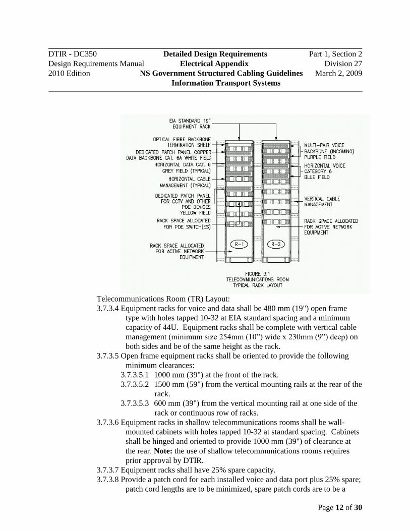
3.7.3 Equipment Rack Layouts:
3.7.3.1 Loading of equipment racks within the telecommunications room shall be
as indicated in Figure 3.1, ATelecommunications Room Typical Rack
Layout@. 3.7.3.2 Provide separate equipment racks for voice and data applications.
3.7.3.3 Provide shelving suitable for supporting heavy rack mounted equipment
(e.g. rack mounted UPS).
Serving Floor Area Size Minimum Interior Room
Dimensions
500 m2 3.1m X 2.5m (10’ 2”x 8’ 3”)
Larger than 500 m2 and less than or equal to 800 m
2 3.1m X 2.7m (10’ 2”x 8’ 10”)
Larger than 800 m2 and less than or equal to 1000 m
2 3.1m X 3.4m (10’ 2”x 11’ 2”)
DTIR - DC350 Detailed Design Requirements Part 1, Section 2
Design Requirements Manual Electrical Appendix Division 27
2010 Edition NS Government Structured Cabling Guidelines March 2, 2009
Information Transport Systems
Page 12 of 30
Telecommunications Room (TR) Layout:
3.7.3.4 Equipment racks for voice and data shall be 480 mm (19") open frame
type with holes tapped 10-32 at EIA standard spacing and a minimum
capacity of 44U. Equipment racks shall be complete with vertical cable
management (minimum size 254mm (10”) wide x 230mm (9”) deep) on
both sides and be of the same height as the rack.
3.7.3.5 Open frame equipment racks shall be oriented to provide the following
minimum clearances:
3.7.3.5.1 1000 mm (39") at the front of the rack.
3.7.3.5.2 1500 mm (59") from the vertical mounting rails at the rear of the
rack.
3.7.3.5.3 600 mm (39") from the vertical mounting rail at one side of the
rack or continuous row of racks.
3.7.3.6 Equipment racks in shallow telecommunications rooms shall be wall-
mounted cabinets with holes tapped 10-32 at standard spacing. Cabinets
shall be hinged and oriented to provide 1000 mm (39") of clearance at
the rear. Note: the use of shallow telecommunications rooms requires
prior approval by DTIR.
3.7.3.7 Equipment racks shall have 25% spare capacity.
3.7.3.8 Provide a patch cord for each installed voice and data port plus 25% spare;
patch cord lengths are to be minimized, spare patch cords are to be a

DTIR - DC350 Detailed Design Requirements Part 1, Section 2
Design Requirements Manual Electrical Appendix Division 27
2010 Edition NS Government Structured Cabling Guidelines March 2, 2009
Information Transport Systems
Page 13 of 30
variety of lengths to a maximum of 5m (15’).
3.7.3.9 Provide horizontal cable management for owner supplied active network
equipment. The horizontal cable management provided for this
equipment shall be equal in number to the horizontal cable management
provided for the patch panels.
3.7.3.10 Populate unused / spare ports in all patch panels with modular
connectors colour coded to match the active ports in the patch panel.
3.7.3.11 Cable tray shall be installed around the perimeter of the
telecommunications room to facilitate service cable loops, sufficient
cable support and organization.
3.7.3.12 Cable tray shall be installed above all equipment racks, spanning across
the perimeter cable tray, to facilitate cable support, cable drops and
organization.
3.7.3.13 Cable tray shall be ladder type or wire basket type.
3.8 Equipment Room (ER)
3.8.1 Copper Terminations:
3.8.1.1 Horizontal and backbone cabling shall be terminated on patch panels
containing eight-position connectors with T568A pin/pair assignments
using insulation displacement connectors (IDC).
3.8.1.2 Voice backbone cabling shall be terminated using two pairs per connector
(pairs 1 and 2).
3.8.1.3 Horizontal distribution and backbone cabling system termination panels
within the ER space shall be maximum 48 port capacity.
3.8.1.4 ER patch panels shall occupy a maximum of 2U rack space per individual
panel.
3.8.1.5 Connectors shall be colour coded as follows:
3.8.1.5.1 White for copper data backbone cabling.
3.8.1.5.2 Orange for incoming voice backbone cabling from the
demarcation point.
3.8.1.5.3 Purple for outgoing voice backbone cabling.
3.8.1.5.4 Grey for data horizontal cabling.
3.8.1.5.5 Blue for voice horizontal cabling.
3.8.1.5.6 Yellow for special applications (POE, CCTV, etc.) horizontal
cabling.
3.8.2 Optical Fibre Terminations:
3.8.2.1 Horizontal and backbone cabling shall be terminated on patch panels
containing duplex 568SC connectors.
3.8.3 Equipment Rack Layouts:
3.8.3.1 Loading of equipment racks within the equipment room shall be as

DTIR - DC350 Detailed Design Requirements Part 1, Section 2
Design Requirements Manual Electrical Appendix Division 27
2010 Edition NS Government Structured Cabling Guidelines March 2, 2009
Information Transport Systems
Page 14 of 30
indicated in Figure 3.2, AEquipment Room Typical Rack Layout@. 3.8.3.2 Provide separate equipment racks for voice and data applications.
3.8.3.3 Provide shelving suitable for supporting heavy rack mounted equipment
(e.g. rack mounted UPS).
3.8.4 ER Layout:
3.8.4.1 Equipment racks for voice and data shall be 480 mm (19") open frame
type with holes tapped 10-32 at EIA standard spacing and a minimum
capacity of 44U. Equipment racks shall be complete with vertical cable
management (minimum size 254mm (10”) wide x 230mm (9”) deep) on
both sides and be of the same height as the rack.
DTIR - DC350 Detailed Design Requirements Part 1, Section 2
Design Requirements Manual Electrical Appendix Division 27
2010 Edition NS Government Structured Cabling Guidelines March 2, 2009
Information Transport Systems
Page 15 of 30
3.8.4.2 Open frame equipment racks shall be oriented to provide the following
minimum clearances:
3.8.4.2.1 1000 mm (39") at the front of the rack.
3.8.4.2.2 1500 mm (59") from the vertical mounting rails at the rear of the
rack.
3.8.4.2.3 600 mm (39") from the vertical mounting rail at one side of the
rack or continuous row of racks.
3.8.4.3 Equipment racks shall have 25% spare capacity.
3.8.4.4 Provide horizontal cable management for owner supplied active network
equipment. The horizontal cable management provided for this
equipment shall be equal in number to the horizontal cable management
provided for the patch panels.
3.8.4.5 Provide a patch cord for each installed voice and data port plus 25% spare;
patch cord lengths are to be minimized, spare patch cords are to be a
variety of lengths to a maximum of 5m (15’).
3.8.4.6 Populate unused / spare ports in all patch panels with modular connectors
colour coded to match the active ports in the patch panel.
3.8.4.7 Cable tray shall be installed around the perimeter of the equipment room
to facilitate cable service loops, sufficient cable support and
organization.
3.8.4.8 Cable tray shall be installed above all equipment racks, spanning across
the perimeter cable tray, to facilitate cable support, cable drops and
organization.
3.8.4.9 Cable tray shall be ladder type or wire basket type.
3.9 Entrance Facilities
3.9.1 Building Telecommunications Demarcation:
3.9.1.1 The building information transport system demarcation facilities shall
include three basic components:
3.9.1.1.1 Building cross-connect hardware.
3.9.1.1.2 Demarcation backbone cable.
3.9.1.1.3 Building demarcation termination hardware.

DTIR - DC350 Detailed Design Requirements Part 1, Section 2
Design Requirements Manual Electrical Appendix Division 27
2010 Edition NS Government Structured Cabling Guidelines March 2, 2009
Information Transport Systems
Page 16 of 30
3.9.1.2 Demarcation connectors shall be RJ21X female for the service provider
and RJ21X male for the building.
3.9.1.3 The layout shall be as indicated in Figure 3.3, ABuilding
Telecommunications Demarcation@.
3.9.2 Entrance Cables
3.9.2.1 Outside plant (OSP) cables shall be exposed within the premise for a
maximum of 15 m (50 ft) from the building entrance.
3.9.2.2 OSP entrance cables may only extend beyond 15 meters provided they are
enclosed in rigid conduit.
3.10 Field Testing
3.10.1 UTP Horizontal Cable Testing:
3.10.1.1 Cables shall be tested in accordance with the latest approved testing
procedures with Level IIIe field test instruments.
3.10.2 UTP Backbone Cable Testing:
3.10.2.1 Field testing acceptance parameters for Category 3 backbone cabling shall
be:
3.10.2.1.1 Wire map.

DTIR - DC350 Detailed Design Requirements Part 1, Section 2
Design Requirements Manual Electrical Appendix Division 27
2010 Edition NS Government Structured Cabling Guidelines March 2, 2009
Information Transport Systems
Page 17 of 30
3.10.2.1.2 Length.
3.10.2.2 Field testing acceptance parameters for augmented Category 6 backbone
cabling shall be the same as for the permanent link.
3.10.3 Coaxial Cable Testing
3.10.3.1 All coaxial cabling used in broadband applications shall be tested for the
following acceptance parameters:
3.10.3.1.1 DC loop resistance.
3.10.3.1.2 Impedance.
3.10.3.1.3 Length.
3.10.3.1.4 TDR.
3.10.3.1.5 Attenuation.
3.10.3.1.6 Noise.
3.10.4 Optical Fibre Cable Testing:
3.10.4.1 Multimode cables shall be tested using Method B of TIA-526-14-A.
3.10.4.2 Singlemode cables shall be tested using Method A.1 of TIA-526-7.
3.11 System Administration
3.11.1 General
3.11.1.1 The requirements for system administration are Class 2 specified within
the ANSI/EIA/TIA-606-A standard which provides for the Information
Transport System (ITS) infrastructure administration needs within a
single building.
3.11.1.2 A unique identifier is to be associated with each element of the ITS
infrastructure to be administered.
3.11.1.3 All components of the ITS administration system shall be designed and
installed to last the intended life (20 year warranty period) of the ITS
system installed.
3.11.2 Telecommunications Spaces
3.11.2.1 All telecommunications spaces within a building shall be uniquely
identified as part of a complete administration system. The TR, ER or
MTR shall be identified by the room designation assigned by the
architectural design. The assigned number shall be used within the
administration system identifier and shall be a “lamicoid” type plate
minimum (50mm H) X (300mm L) as shown below and secured to the
exterior of the door frame entering that space.

DTIR - DC350 Detailed Design Requirements Part 1, Section 2
Design Requirements Manual Electrical Appendix Division 27
2010 Edition NS Government Structured Cabling Guidelines March 2, 2009
Information Transport Systems
Page 18 of 30
TR - 234
Denotes Telecommunications Room (TR)
Denotes Architectural Room Number
300mm
50mm
3.11.2.2 All telecommunications equipment racks within the telecommunications
space require a unique component identifier as part of the administration
system by a “lamicoid” nameplate, minimum (50mm H) X (600mm L) as
shown below and secured to the upper horizontal rail of the equipment
rack.
3.11.2.3 All ITS termination hardware within the telecommunications space
requires a unique component identifier as part of the administration
system. Identifiers must be self adhesive thermal transfer type and
placed appropriately to indicate all ports.
3.11.3 Horizontal Distribution System
3.11.3.1 All horizontal cabling shall be uniquely identified with a wrap type self-
laminating adhesive label with mechanically generated (not hand written)
identifier.
3.11.3.2 Horizontal cable identifiers shall denote basic information transport
system application and originating telecommunications space termination
equipment port as shown;
DTIR - DC350 Detailed Design Requirements Part 1, Section 2
Design Requirements Manual Electrical Appendix Division 27
2010 Edition NS Government Structured Cabling Guidelines March 2, 2009
Information Transport Systems
Page 19 of 30
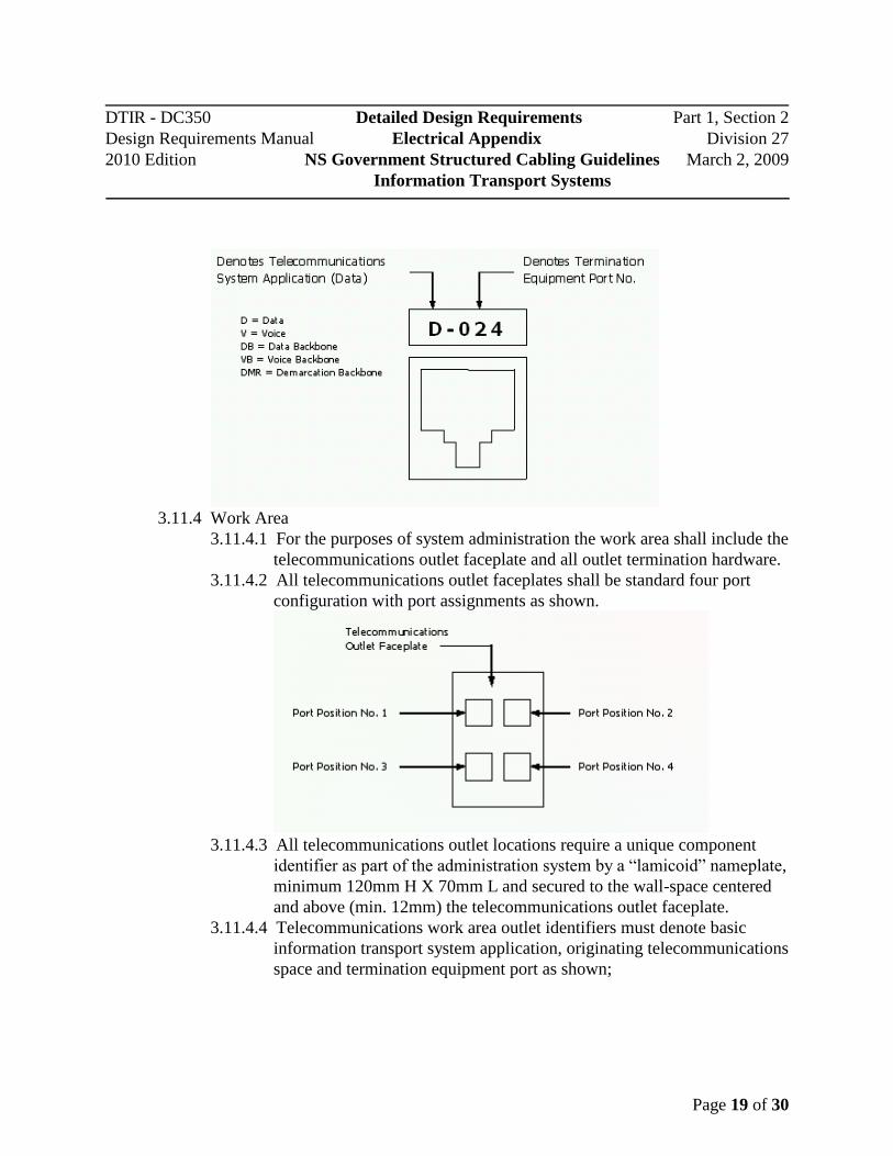
3.11.4 Work Area
3.11.4.1 For the purposes of system administration the work area shall include the
telecommunications outlet faceplate and all outlet termination hardware.
3.11.4.2 All telecommunications outlet faceplates shall be standard four port
configuration with port assignments as shown.
3.11.4.3 All telecommunications outlet locations require a unique component
identifier as part of the administration system by a “lamicoid” nameplate,
minimum 120mm H X 70mm L and secured to the wall-space centered
and above (min. 12mm) the telecommunications outlet faceplate.
3.11.4.4 Telecommunications work area outlet identifiers must denote basic
information transport system application, originating telecommunications
space and termination equipment port as shown;
DTIR - DC350 Detailed Design Requirements Part 1, Section 2
Design Requirements Manual Electrical Appendix Division 27
2010 Edition NS Government Structured Cabling Guidelines March 2, 2009
Information Transport Systems
Page 20 of 30
3.11.5 Backbone System
3.11.5.1 All backbone system cabling shall be uniquely identified with a wrap
type self-laminating adhesive label with mechanically generated (not
hand written) identifier.
3.11.5.2 Backbone cable identifiers shall denote basic information transport
system application and originating telecommunications space as shown;
3.11.6 Telecommunications Demarcation Facilities
3.11.6.1 For the purposes of system administration, the information transport
system demarcation facilities shall include three basic components;
3.11.6.1.1 Building cross-connect hardware.
3.11.6.1.2 Building demarcation backbone cable
3.11.6.1.3 Building demarcation termination hardware.

DTIR - DC350 Detailed Design Requirements Part 1, Section 2
Design Requirements Manual Electrical Appendix Division 27
2010 Edition NS Government Structured Cabling Guidelines March 2, 2009
Information Transport Systems
Page 21 of 30
3.11.6.2 All Building cross-connect hardware within the telecommunications
space requires a unique component identifier as part of the administration
system. Identifiers must be self adhesive thermal transfer type and
placed appropriately to indicate applicable pair assignments as shown;
3.11.7 All information transport system demarcation backbone cabling shall be uniquely
identified with a wrap type self-laminating adhesive label with mechanically
generated (not hand written) identifier.
3.11.8 All information transport system demarcation backbone cable identifiers shall
denote basic telecommunications system application and originating
telecommunications space as shown;
DTIR - DC350 Detailed Design Requirements Part 1, Section 2
Design Requirements Manual Electrical Appendix Division 27
2010 Edition NS Government Structured Cabling Guidelines March 2, 2009
Information Transport Systems
Page 22 of 30
4 Consultant Services Requirements
4.1 Basic Elements
4.1.1 The CAN/CSA, ANSI/TIA/EIA and BICSI standards as listed in Section 2 of this
document define the basic elements of the Information Transport System (ITS)
cabling structure. Design consultants providing services to the Province of Nova
Scotia shall prepare contract documents as detailed within this section.
4.2 General Requirements
4.2.1 Consultants shall submit the following for ITS infrastructure projects:
4.2.1.1 Technical specifications.
4.2.1.2 Information Transport System drawings.
4.3 Technical Specifications
4.3.1 Document Requirements:
4.3.1.1 Consultants shall produce a complete tender document sub-section A Information Transport System Distribution@ within the electrical
specifications.
4.3.1.2 The ITS distribution system document shall be formatted in three parts:
4.3.1.2.1 Part 1 - General.
4.3.1.2.2 Part 2 - Products.
4.3.1.2.3 Part 3 - Execution.
4.3.2 Part 1 - General:
4.3.2.1 This portion identifies the overall general requirements of the project in
reference to the provisioning of ITS infrastructure.
4.3.2.2 This section shall provide ITS technical specifications within the
following sub-sections as required by the project:
4.3.2.2.1 Summary.
4.3.2.2.2 References (identified in Section 2 of this document).
4.3.2.2.3 Permits, fees and certificates of approval.
4.3.2.2.4 System description.
4.3.2.2.5 Submittals.
4.3.2.2.6 Quality assurance.
4.3.2.2.7 Warranty requirements.
4.3.2.2.8 Delivery, storage and handling.
4.3.2.2.9 Sequence and scheduling.
4.3.2.2.10 Use of site.
4.3.2.2.11 Continuity of services.

DTIR - DC350 Detailed Design Requirements Part 1, Section 2
Design Requirements Manual Electrical Appendix Division 27
2010 Edition NS Government Structured Cabling Guidelines March 2, 2009
Information Transport Systems
Page 23 of 30
4.3.3 Part 2 - Products:
4.3.3.1 This portion identifies general requirements of the individual components
incorporated in the provisioning of ITS infrastructure.
4.3.3.2 This section shall provide ITS technical specifications within the
following sub-sections as required by the project:
4.3.3.2.1 Acceptable manufacturers.
4.3.3.2.2 Fabrication.
4.3.3.2.3 Suitability.
4.3.3.2.4 Voice/data building backbone cable (including optical backbone
cabling as required).
4.3.3.2.5 Voice horizontal distribution cable.
4.3.3.2.6 Data horizontal distribution cable.
4.3.3.2.7 Optical fibre horizontal distribution cable (as required).
4.3.3.2.8 Campus backbone cable (campus (inter-building) applications).
4.3.3.2.9 Service provider entrance facilities.
4.3.3.2.10 Voice/data/optical fibre work area outlets.
4.3.3.2.11 Termination Blocks.
4.3.3.2.12 Patch panels.
4.3.3.2.13 Optical fibre patch panels.
4.3.3.2.14 Patch cords and jumper cables.
4.3.3.2.15 Equipment racks and cabinets.
4.3.3.2.16 Building entrance protectors (campus backbone cabling).
4.3.3.2.17 Spare parts.
4.3.4 Part 3 - Execution:
4.3.4.1 This portion identifies construction and installation requirements for
system vendors when provisioning ITS infrastructure.
4.3.4.2 This section shall provide ITS technical specifications within the
following sub-sections as required by the project:
4.3.4.2.1 Site survey.
4.3.4.2.2 Handling of materials.
DTIR - DC350 Detailed Design Requirements Part 1, Section 2
Design Requirements Manual Electrical Appendix Division 27
2010 Edition NS Government Structured Cabling Guidelines March 2, 2009
Information Transport Systems
Page 24 of 30
4.3.4.2.3 Protection of Owner=s facilities.
4.3.4.2.4 Installation.
4.3.4.2.5 Grounding and Bonding.
4.3.4.2.6 Labelling and administration.
4.3.4.2.7 Testing and certification.
4.3.4.2.8 Field quality control.
4.3.4.2.9 RCDD project manager requirement
4.3.4.2.10 Customer/Owner orientation and training.
4.3.4.2.11 Project documentation.
4.4 Information Transportation System (ITS) Drawings
4.4.1 Drawing File Requirements:
4.4.1.1 Consultants shall produce contract document drawings and details within
the electrical drawings.
4.4.1.2 Consultants shall make drawing files available to the successful project
vendor in AutoCAD (.dwg file format) to assist with vendor compliance
requirements.
4.4.1.3 AutoCAD generated drawing files shall be produced to address the
following requirements:
4.4.1.3.1 Floor plan drawings.
4.4.1.3.2 Information transport distribution system details.
4.4.1.3.3 Telecommunications space - rack details.
4.4.1.3.4 Telecommunications space - floor layout.
4.4.1.3.5 Information transport system backbone – riser diagram.
4.4.1.3.6 Information transport system grounding and bonding - riser
diagram.
4.4.2 Floor Plan Drawings:
4.4.2.1 Floor plan drawings shall indicate the location of the following
information transport system cabling components:
4.4.2.1.1 Work area outlet location.
4.4.2.1.2 Communications outlet type (icon specified).
4.4.2.1.3 Communications outlet configuration (icon specified).
4.4.2.1.4 Serving telecommunications space location.
4.4.2.1.5 Special requirements/considerations notes.
4.4.3 Information Transport System Distribution Details:
4.4.3.1 System detail drawings shall provide additional information required for
information transport system cabling components including:
4.4.3.1.1 Outlet icon details and descriptions.
4.4.3.1.2 Special application details.

DTIR - DC350 Detailed Design Requirements Part 1, Section 2
Design Requirements Manual Electrical Appendix Division 27
2010 Edition NS Government Structured Cabling Guidelines March 2, 2009
Information Transport Systems
Page 25 of 30
4.4.3.1.3 Special installation requirements.
4.4.3.1.4 Architectural details (as required).
4.4.4 Telecommunications Space - Rack Details:
4.4.4.1 Rack detail drawings shall provide rack elevations for each
telecommunications space within the entire project scope.
4.4.4.2 Rack elevation drawings shall provide detailed information for all ITS
distribution system components within the Telecommunications Room(s)
(TR) and Equipment Room (ER) including:
4.4.4.2.1 Equipment rack/cabinet dimensions and requirements.
4.4.4.2.2 Equipment rack/cabinet quantities.
4.4.4.2.3 Termination hardware and loading requirements for:
4.4.4.2.3.1.1 Quantity.
4.4.4.2.3.1.2 Placement.
4.4.4.2.3.1.3 Category requirement.
4.4.4.2.3.1.4 Port count (active / spare).
4.4.4.2.3.1.5 System application (e.g. horizontal or backbone).
4.4.4.2.4 Additional hardware requirements (e.g. horizontal managers,
power bars or UPS).
4.4.5 Telecommunications Space - Floor Layout:
4.4.5.1 Telecommunications space floor layout drawings shall be scale drawings
and indicate orientation of equipment and hardware as assigned to the
footprint of the space.
4.4.5.1.1 Floor layout drawings shall provide detailed information for all
ITS infrastructure components within the TR and ER including:
4.4.5.1.1.1 Equipment rack/cabinet location and orientation.
4.4.5.1.1.2 Horizontal pathway requirements, location and
orientation.
4.4.5.1.1.3 Backbone pathway requirements, location and
orientation.
4.4.5.1.1.4 Information transport system requirements, location
and orientation (e.g. voice and data
telecommunications outlet).
4.4.5.1.1.5 Associated electrical distribution system
requirements, location and orientation.
4.4.5.1.1.6 Dimensional and work clearance information.

DTIR - DC350 Detailed Design Requirements Part 1, Section 2
Design Requirements Manual Electrical Appendix Division 27
2010 Edition NS Government Structured Cabling Guidelines March 2, 2009
Information Transport Systems
Page 26 of 30
4.4.6 Information Transport System Backbone (Riser Diagram):
4.4.6.1 Information transport system backbone drawings shall be single-line type
drawings to indicate quantity requirements and associated pathway
assignments for all building and campus backbone cabling.
4.4.6.2 Backbone system drawings shall provide detailed information for all ITS
backbone cabling within and between the TR(s) and ER including:
4.4.6.2.1 Backbone cable type and requirements.
4.4.6.2.2 Backbone cable quantity.
4.4.6.2.3 Information transport systems application.
4.4.6.2.4 Pathway assignment.
4.4.6.2.5 Termination hardware type and location.
4.4.7 Information transport system grounding and bonding - riser diagram.
4.4.7.1 Information transport system backbone drawings shall be single-line type
drawings to indicate size/quantity requirements and associated pathway
assignments for all information transport system grounding and bonding
cabling.
4.4.7.2 Grounding and bonding system drawings shall provide detailed
information for all ITS grounding and bonding cabling associated with
this system including:
4.4.7.2.1 Grounding and bonding cable type and requirements.
4.4.7.2.2 Grounding and bonding cable quantity.
4.4.7.2.3 Grounding and bonding bus bar sizing.
4.4.7.2.4 Grounding and bonding bus bar location.
4.4.7.2.5 Information transport systems application.
4.4.7.2.6 Pathway assignment.
4.4.7.2.7 Termination hardware type and location.

DTIR - DC350 Detailed Design Requirements Part 1, Section 2
Design Requirements Manual Electrical Appendix Division 27
2010 Edition NS Government Structured Cabling Guidelines March 2, 2009
Information Transport Systems
Page 27 of 30
5 Vendor Requirements
5.1 Basic Elements
5.1.1 The CAN/CSA, ANSI/TIA/EIA and BICSI standards as listed in Section 2 of this
document define the basic elements of the Information Transport System (ITS )
cabling structure. Vendor firms providing services to the Province of Nova Scotia
shall comply with the qualifications criteria as detailed within this section.
5.2 Vendor Qualifications
5.2.1 General:
5.2.1.1 Vendor firms providing services to the Province of Nova Scotia shall
comply with Section 3 of this document.
5.2.1.2 Qualified vendors shall provide technical field services in compliance with
labour standards (e.g. Communications Cabling Specialist (CCS)).
5.2.1.3 Vendors shall comply with all applicable Nova Scotia Workers
Compensation requirements.
5.2.1.4 Vendors shall maintain current Nova Scotia Construction Safety
Association (NSCSA) compliant status.
5.2.1.5 Qualified vendors shall maintain current Building Industry Constructions
Services International (BICSI) membership.
5.2.1.6 Qualified vendors shall maintain manufacturer recognition as a certified
installation contractor for the ITS product solution being implemented.
5.3 RCDD Project Manager
5.3.1 General
5.3.1.1 The successful Information Transport Distribution System contractor is
required to retain the services of one (1) Registered Communications
Distribution Designer (RCDD) for the duration of the project. The
RCDD must be identified and the successful vendor must provide a copy
of the RCDD current certificate and BICSI membership on a timely basis
prior to award of the contract.
5.3.1.2 The RCDD shall maintain responsibility for the following;
5.3.1.2.1 Review and accept the Information Transport Distribution
System materials, hardware and related components proposed.
5.3.1.2.2 Review the proposed pathways and spaces and accept the size
and location of all Telecommunications Spaces (TS).
5.3.1.2.3 Notify the Consultant of any issues or concerns related to
CAN/CSA, IEE and TIE/EIA specification compliance.
5.3.1.2.4 Review and approve Information Transport Distribution System

DTIR - DC350 Detailed Design Requirements Part 1, Section 2
Design Requirements Manual Electrical Appendix Division 27
2010 Edition NS Government Structured Cabling Guidelines March 2, 2009
Information Transport Systems
Page 28 of 30
material shop drawings prior to submission to the Consultant.
5.3.1.2.5 Attend regularly scheduled project construction and job
meetings as requested by the project Consultant.
5.3.1.2.6 Ensure system installation practices and procedures comply with
all applicable CAN/CSA, IEE and TIE/EIA specifications and
procedures.
5.3.1.2.7 Provide regular project status reports and updates as requested
by the project Consultant.
5.3.1.2.8 Observe testing and certification procedures and provide
manufacturers assurance and warranty.
5.3.1.2.9 Review and approve all project as-built documentation
including drawings, test reports, details and provide current
RCDD seal on all.
5.4 Certification and Testing
5.4.1 General:
5.4.1.1 Vendors providing services to the Province of Nova Scotia shall provide
Product Manufacturer=s Application Warranty for a minimum of twenty
years.
5.4.1.2 Certification and testing documentation shall be provided as a complete
part of the project documentation requirements as specified in Section 6
of this document. Documentation shall include a RCDD letter of
certification for the complete Information Transport System cabling for
the project.

DTIR - DC350 Detailed Design Requirements Part 1, Section 2
Design Requirements Manual Electrical Appendix Division 27
2010 Edition NS Government Structured Cabling Guidelines March 2, 2009
Information Transport Systems
Page 29 of 30
6 Project Documentation
6.1 Basic Elements
6.1.1 The CAN/CSA, ANSI/TIA/EIA and BICSI standards as listed in Section 2 of this
document define the basic elements of the Information Transport System (ITS)
cabling structure. Vendor firms providing services to the Province of Nova Scotia
shall prepare and submit project documentation as detailed within this section.
6.2 As-built Drawings
6.2.1 General:
6.2.1.1 Vendors shall prepare record drawings in both hard copy and AutoCAD
drawing format on CDROM as part of compliance with this requirement.
6.2.1.2 Drawings in AutoCAD .dwg file format shall be provided to the vendor
by the consulting services provider for the compliance of this section.
6.2.1.3 Record drawings shall provide the following information:
6.2.1.3.1 All work area telecommunications outlet locations as
constructed.
6.2.1.3.2 Project administration system identifiers for telecommunications
outlets.
6.2.1.3.3 Project administration system identifiers for telecommunication
spaces (TR and ER).
6.2.1.4 Hard copy format record drawings shall be provided in two complete sets
as defined:
6.2.1.4.1 One complete floor plan and riser drawing set, black and white
(colour optional).
6.2.1.4.2 One complete floor plan drawing set, black and white (colour
optional), is to be provided and mounted under plexiglass in all
associated telecommunications spaces.
6.2.1.4.3 One complete backbone riser drawing set, black and white
(colour optional), is to be provided and mounted under
plexiglass in the main telecommunications room.
6.2.1.4.4 One complete grounding / bonding riser drawing set, black and
white (colour optional), is to be provided and mounted under
plexiglass in the main telecommunications room).
6.3 Test Results
6.3.1 Vendors shall provide test results hard (paper) copy and in digital format on
CDROM as part of compliance with this requirement.

DTIR - DC350 Detailed Design Requirements Part 1, Section 2
Design Requirements Manual Electrical Appendix Division 27
2010 Edition NS Government Structured Cabling Guidelines March 2, 2009
Information Transport Systems
Page 30 of 30
6.4 Manufacturer=s Warranty
6.4.1 General:
6.4.1.1 Vendors shall provide a manufacturer generated and support Product
Warranty and Application Assurance certificates upon completion of
installation and acceptance by NSDTIR.
6.4.1.2 Product warranty and appliance assurance shall provide coverage of
materials and labour for a minimum of Twenty Years from date of
installation and acceptance regardless of installing agent/vendor status.
6.5 RCDD Project Certification
6.5.1 General
6.5.1.1 Vendors shall provide RCDD Project Certificate in hard copy format as
part of compliance with this requirement.
6.5.1.2 The RCDD certification shall be provided for compliance as per the
requirements within this document.