Embed Size (px)
Citation preview

1
Providing Energy for Space Systems
Steven E. Johnson United Space Alliance, LLC ISS Flight ControllerNASA Johnson Space Center
NASA/NTSA SymposiumLiving and Working in Space: Energy
4 November 2006
Photo taken January 26, 2003 by the crew of Space Shuttle Columbia
Copyright © 2006 by United Space Alliance, LLC. These materials are sponsored by the National Aeronautics and Space Administration under Contract NAS9-20000 and Contract NNJ06VA01C. The U.S. Government retains a paid-up, nonexclusive, irrevocable worldwide license in such materials to reproduce, prepare, derivative works, distribute copies to the public, and perform publicly and display publicly, by or on behalf of the U.S. Government. All other rights are reserved by the copyright owner.

2
Overview
• Objectives• Energy• Energy Systems• Nuclear Power • Energy Storage• Solar Power• ISS• Summary• Theoretical Applications• Backup Material
3
Learning Objectives
• After reviewing the presentation, participants will: – List the three types of spacecraft power systems. – State advantages and disadvantages of spacecraft power
system types. – Describe the ISS Electrical Power System. – Identify the type of power system theoretical spacecraft should
employ.
4
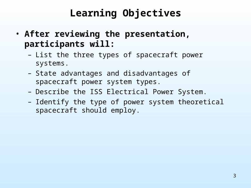
SpacecraftPowerSystemOptions
Solar NuclearEnergyStorage
Photo-Voltaic*
SolarDynamic
Fission Radioisotope Chemical* Mechanical
Energy Systems 101Powering Spacecraft
*Current manned space systems use Photovoltaic and Chemical power
5
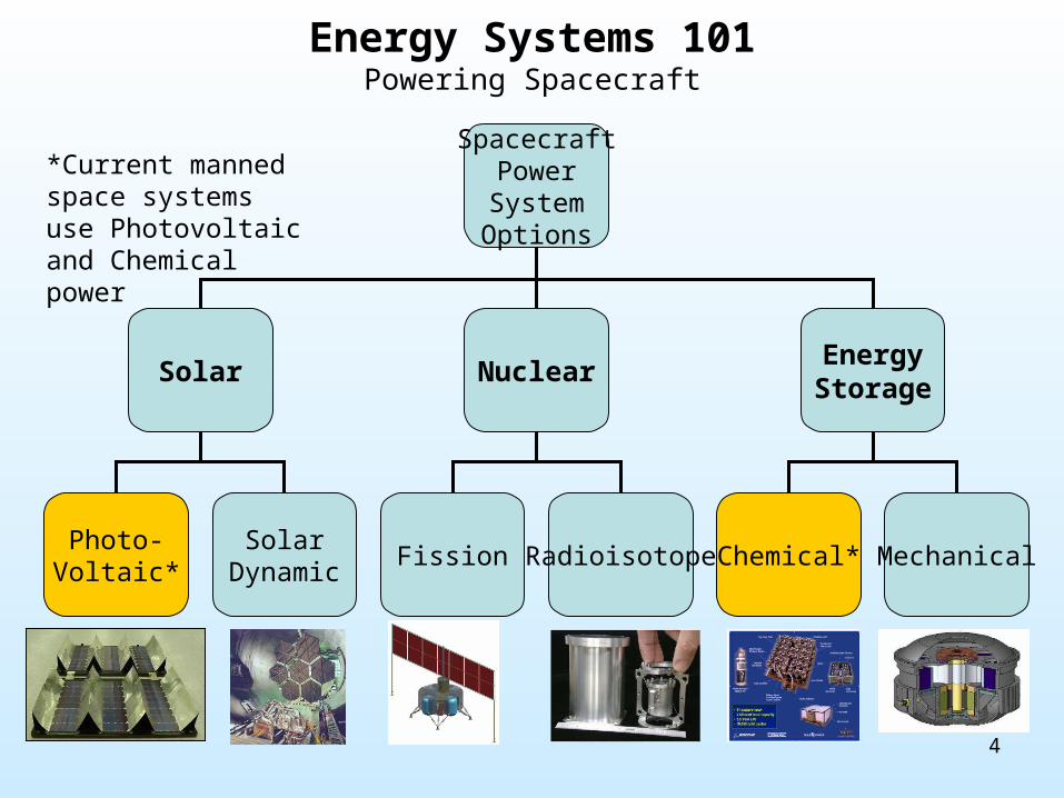
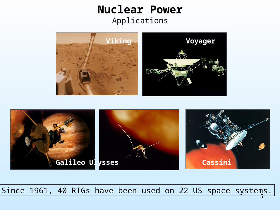
Nuclear PowerApplications
Voyager
Galileo Ulysses Cassini
Viking
Since 1961, 40 RTGs have been used on 22 US space systems.

6
Nuclear PowerEvaluation
• Nuclear Power Advantages• Radioisotope Thermoelectric Generators (RTG) use the natural decay of
plutonium to produce heat, which is directly transformed into electricity through a thermocouple device.
– Provides a very long-term energy source• Supports mission duration of tens of years
– Allows independent space system operation• Not dependent on illumination source
– Solar pointing system not required• Most space craft require control systems for attitude control
regardless of power system
– Currently the only viable option for non-solar missions longer than ~2 weeks and missions traveling beyond Mars
→ Best option for deep-space unmanned missions

7
Nuclear PowerEvaluation
• Nuclear Power Disadvantages– Low power capability
• Highest power application: Cassini, < 1 kW• Not practical for manned space systems
– Expensive– Requires custom-built system for each application
→ Unfeasible option for manned missions

8
Energy StorageApplications
Cassini ProbeCassini Probe
ApolloLunar Rover
Space ShuttleSpace Shuttle
ApolloCommand ServiceModule
Gemini
EMU

9
Energy StorageEvaluation
• Energy Storage Advantages• Energy Storage devices include batteries, which stores chemical energy
and makes it available in an electrical form; and fuel cells, which produce electricity from an external supply of fuel (usually hydrogen) and oxygen.
– Allows independent space system operation• Not dependent on illumination source
– Solar pointing system not required• Most space craft require control systems for attitude control
regardless of power system
→ Best option for limited-duration manned missions

10
Energy StorageEvaluation
• Energy Storage Disadvantages– Limited mission duration
• Fuel or battery life are limited-quantity consumables• Limits mission durations to ~2 weeks
– Requires custom-built system for each application– Fuel Cell systems produce by products (water) which
must be stored/dumped
→ Unfeasible option for long-duration missions
11
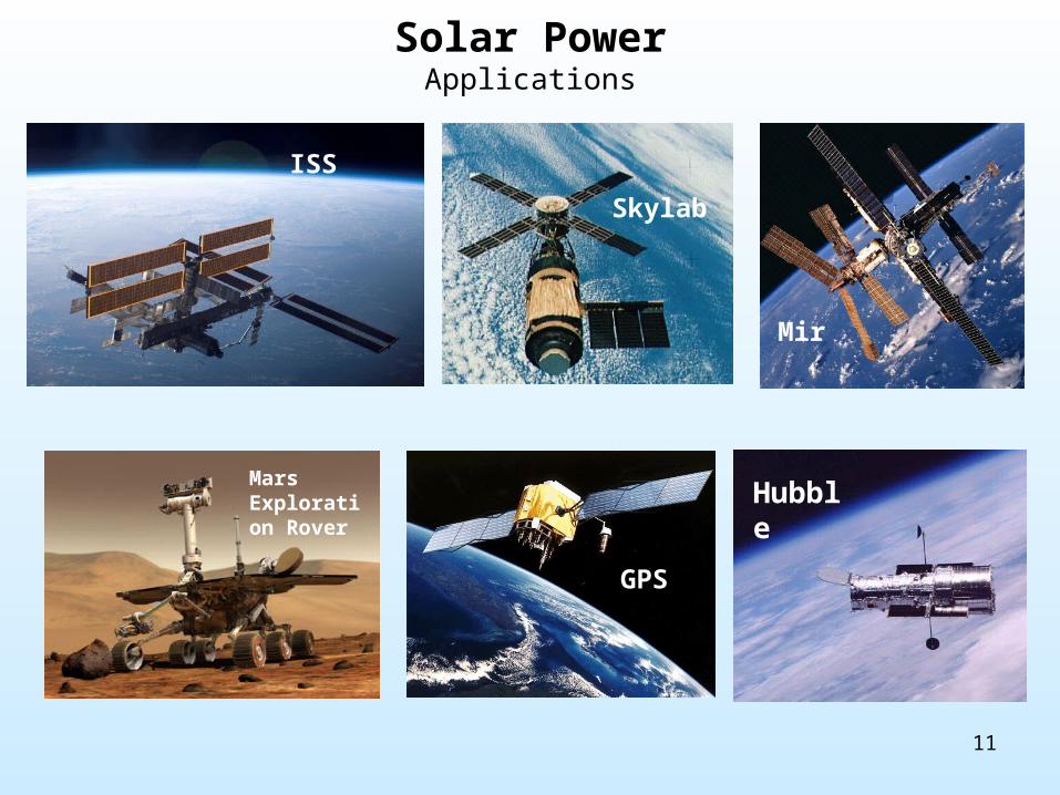
Solar PowerApplications
ISS
Skylab
Mir
Mars Exploration Rover
Mir
GPS
Hubble
12
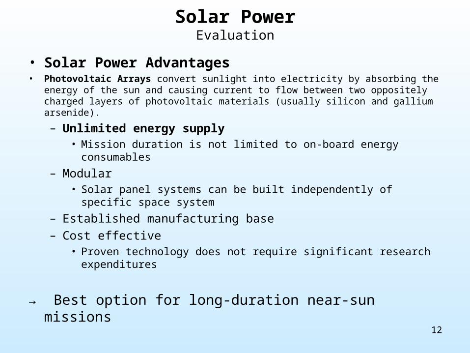
Solar PowerEvaluation
• Solar Power Advantages• Photovoltaic Arrays convert sunlight into electricity by absorbing the energy of the
sun and causing current to flow between two oppositely charged layers of photovoltaic materials (usually silicon and gallium arsenide).
– Unlimited energy supply• Mission duration is not limited to on-board energy consumables
– Modular• Solar panel systems can be built independently of specific space
system
– Established manufacturing base– Cost effective
• Proven technology does not require significant research expenditures
→ Best option for long-duration near-sun missions
13
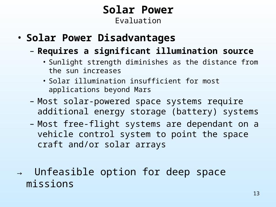
Solar PowerEvaluation
• Solar Power Disadvantages– Requires a significant illumination source
• Sunlight strength diminishes as the distance from the sun increases
• Solar illumination insufficient for most applications beyond Mars
– Most solar-powered space systems require additional energy storage (battery) systems
– Most free-flight systems are dependant on a vehicle control system to point the space craft and/or solar arrays
→ Unfeasible option for deep space missions
14
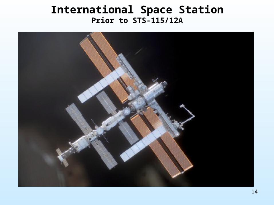
International Space StationPrior to STS-115/12A
15
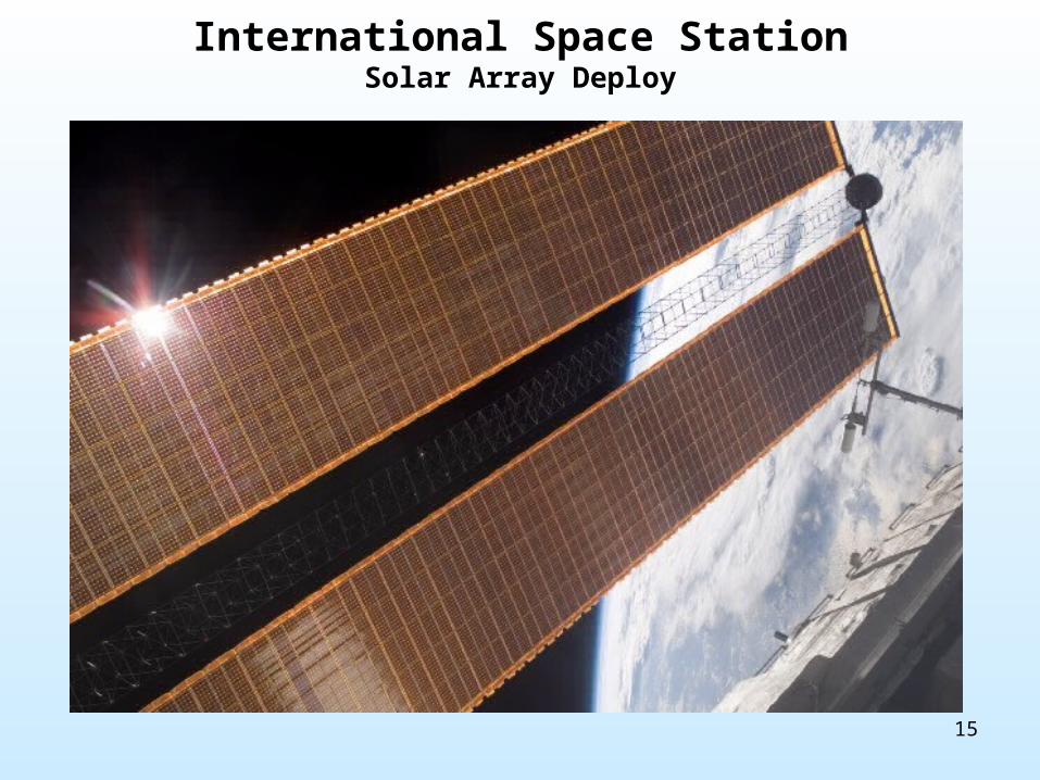
International Space StationSolar Array Deploy
16
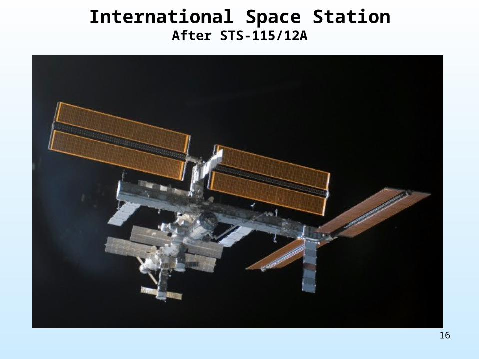
International Space StationAfter STS-115/12A
17
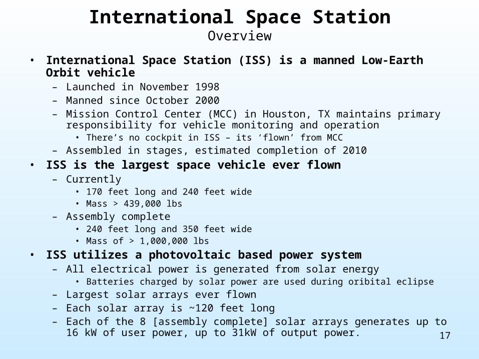
International Space StationOverview
• International Space Station (ISS) is a manned Low-Earth Orbit vehicle– Launched in November 1998– Manned since October 2000– Mission Control Center (MCC) in Houston, TX maintains primary responsibility for
vehicle monitoring and operation• There’s no cockpit in ISS – its ‘flown’ from MCC
– Assembled in stages, estimated completion of 2010
• ISS is the largest space vehicle ever flown– Currently
• 170 feet long and 240 feet wide• Mass > 439,000 lbs
– Assembly complete • 240 feet long and 350 feet wide• Mass of > 1,000,000 lbs
• ISS utilizes a photovoltaic based power system– All electrical power is generated from solar energy
• Batteries charged by solar power are used during oribital eclipse
– Largest solar arrays ever flown– Each solar array is ~120 feet long– Each of the 8 [assembly complete] solar arrays generates up to 16 kW of user
power, up to 31kW of output power.

18
International Space StationAssembly Sequence
STS-121/ULF-1.1
STS-115/12A
STS-116/12A.1
STS-117/13A

19
International Space StationAssembly Sequence
STS-120/10A
STS-119/15A
20
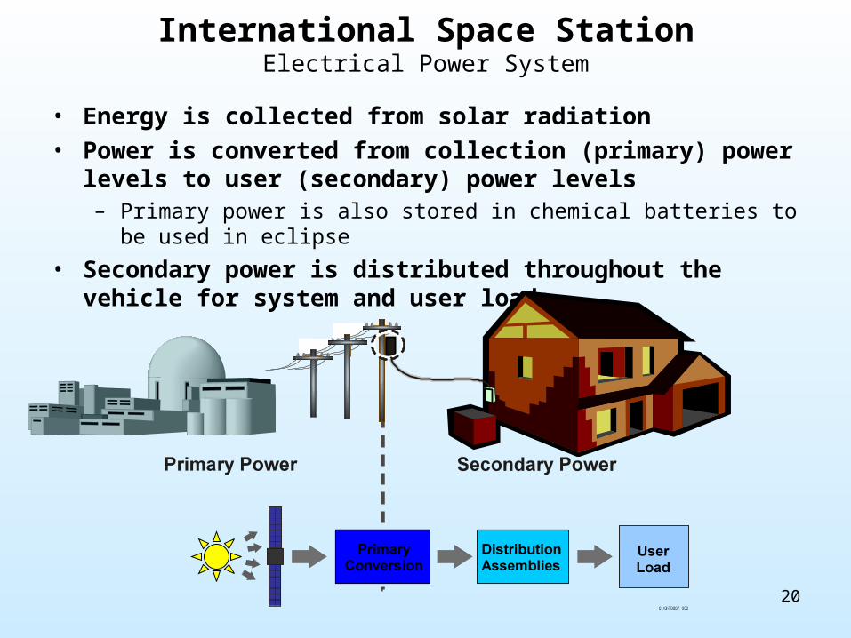
International Space StationElectrical Power System
• Energy is collected from solar radiation• Power is converted from collection (primary) power levels to
user (secondary) power levels– Primary power is also stored in chemical batteries to be used in eclipse
• Secondary power is distributed throughout the vehicle for system and user loads
21
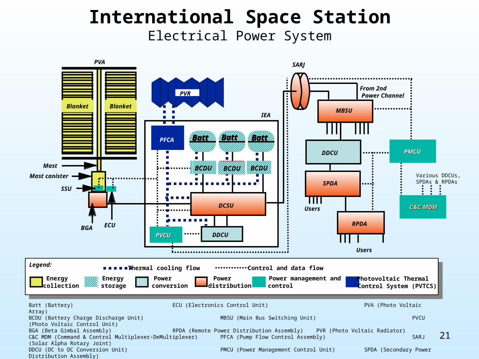
International Space StationElectrical Power System
MBSU
SARJ
BCDU BCDU
PFCA
PVCUPVCU
BattBatt BattBatt BattBatt
PVA
ECU
DCSU
DDCU
BCDU
IEA
Energycollection
BGA
SSU
Mast canister
Blanket Blanket
PVR
Users
Mast
Energystorage
Powerconversion
Powerdistribution
Power management andcontrol
Photovoltaic ThermalControl System (PVTCS)
Thermal cooling flow Control and data flowLegend:
SPDA
DDCU
RPDA
Users
PMCUPMCU
C&C MDMC&C MDMC&C MDM
From 2nd Power Channel
Various DDCUs,SPDAs & RPDAs
Batt (Battery) ECU (Electronics Control Unit) PVA (Photo Voltaic Array) BCDU (Battery Charge Discharge Unit) MBSU (Main Bus Switching Unit) PVCU (Photo Voltaic Control Unit) BGA (Beta Gimbal Assembly) RPDA (Remote Power Distribution Assembly) PVR (Photo Voltaic Radiator) C&C MDM (Command & Control Multiplexer-DeMultiplexer) PFCA (Pump Flow Control Assembly) SARJ (Solar Alpha Rotary Joint) DDCU (DC to DC Conversion Unit) PMCU (Power Management Control Unit) SPDA (Secondary Power Distribution Assembly)
SSU (Sequential Shunt Unit)
22
Summary
• Space systems use three types of power systems
• Each system has advantages and disadvantages
• ISS utilizes a photovoltaic array power system to convert solar energy into electricity

23
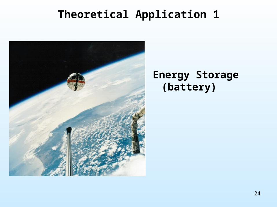
Theoretical Application 1
• Engineering is developing an Extra-Vehicular Activity (EVA) free-ranging, semi-autonomous robotic assistance device for ISS.
• The robotic device will need to operate for the duration of an EVA (~7 hours) or be operated independently from ISS for external inspection and have a mass of 8 kg or less.
• The robotic device will require the following systems– Video camera – 12 V, 40 W
– Still-picture camera – 12V, 25 W
– Flood light – 14 V, 250 W
– Attitude control system – 8 V, 25 W
– EMU-to-ISS Radio Signal Relay – 12 V, 80 W
– Command & Telemetry System – 12 V, 25 W
• What type of energy system should this system utilize?
24
Theoretical Application 1
Energy Storage (battery)

25
Theoretical Application 2
• A space system is required to investigate Jupiter moon Io
• The mission will have the following requirements– Payload up-mass: 850 to 2,200 kg– Payload Dimensions 3 m wide by 7 m long– Translate from Earth to Io in 16 months or less– Operate in orbit around Io for 2-4 years– Enter Io’s atmosphere on a ballistic trajectory and gather
atmospheric data and imagery– Send scientific data back to an Earth control center– Receive instructions from an Earth control center
• What type of energy system should this system utilize?

26
Theoretical Application 2
Nuclear Power

27
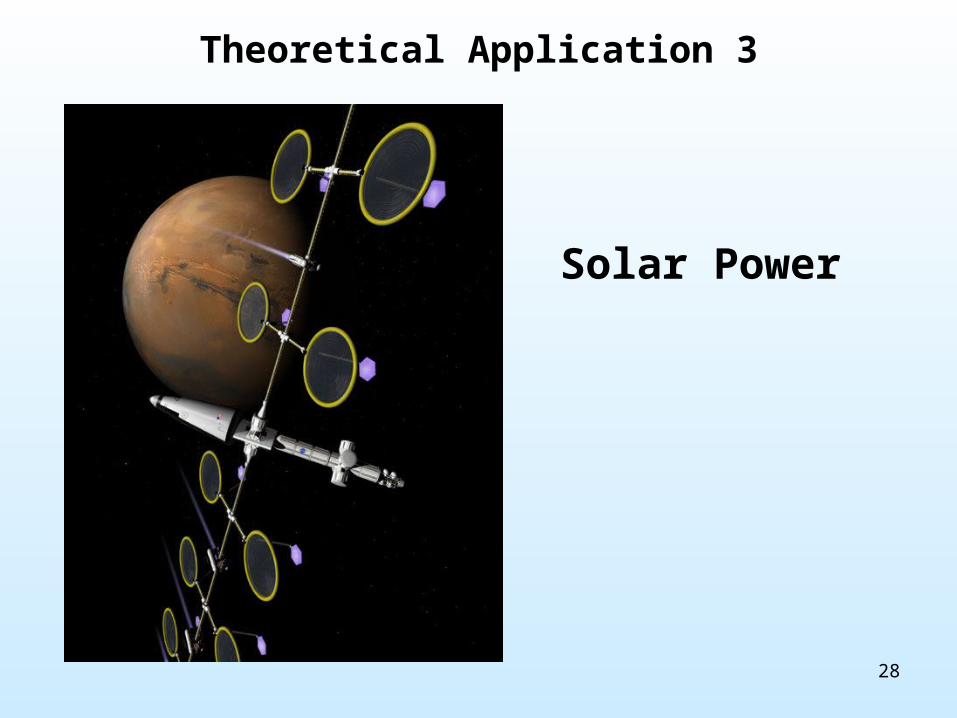
Theoretical Application 3
• A mission has been requested for sun surface observation and space environment sensing
• A space system is required which will have the following mission parameters– Operate in a solar orbit between Mars and Earth for 10+ years– Observe the sun with filtered video and photographic equipment– Sense space weather events– Monitor solar electromagnetic, ultraviolet, infrared, and x-ray
radiation– Send scientific data back to an Earth control center
• What type of energy system should this system utilize?
28
Theoretical Application 3
Solar Power
29
Back Up Material

30
Low Earth Orbit (LEO)Overview
Insolation
(Sunlight)
Earth Orbit
Manned vehicle LEO altitude = 115-400 miles
Orbital Period = ~90 minutes
Insolation = ~45 minutes
Eclipse = ~45 minutes
Diagram Not to Scale
Eclipse
(Night)
31
Manned Space Systems
• There are currently three US manned space systems– ISS– Shuttle– EMU
• ISS is powered by a solar power energy system– Also has an energy storage (battery) component
• Shuttle is powered by a energy storage system– Fuel cell
• EMU is powered by a energy storage system– Battery
32
Space Transportation SystemOverview
• The Space Transportation System is an ascent, Low Earth Orbit, and return space vehicle– Comprised of 3 elements
• 2 Solid Rocket Boosters (SRBs) – Jettisoned ~2 minutes after launch and recovered by ship from Atlantic Ocean
• External Tank – Provides 500,000 gallons of hydrogen and oxygen fuel to Shuttle Main Engines, jettisoned after fuel expended and burns up in Earth’s atmosphere
• Space Shuttle orbiter – Orbits Earth for up to 18 days and then returns as a glider
– First and only operational space vehicle which is reusable• SRBs, Shuttle orbiter, and main engines are refurbished and resupplied for
subsequent missions– Only space system which allows heavy down-mass capability– Orbiter power is provided by 3 oxygen-hydrogen fuel cells
• Each fuel cell generates up to 7 kW of continuous power• Each fuel cell can generate up to 16 kW of short-term (15 min) power
• STS is the only manned US heavy-lift and ascent/return system– Weighs 4,500,000 lbs at lift off– Carries payloads up to 63,500 lbs– Crewed by up to 8 astronauts

33
Extra-vehicular Mobility UnitOverview
• The Extra-vehicular Mobility Unit (EMU) is a self-contained ‘spacesuit’ used by crewmembers to perform Extra-Vehicular Activity (EVA)– The EMU contains all necessary elements for a crewmember to operate
outside of a pressurized vehicle• Battery power system• Pressurized environment• Life Support System• Communication system• Computer, data, and biomedical monitoring system• Urine collection device• Lighting and camera system• Drinking water
• EMU can operate independently for ~7 hours– The air scrubbing cartridge lifetime is the limiting factor in EVA
• Similar Russian designed and built spacesuit (“Orlan”) used on ISS

34
Extra-Vehicular Mobility Unit Power System
• EMU battery operates at 16.8 V– Capacity = 26.8 A-Hr– Produces ~70 W of power– Useful power supplied
for ~7 hours
• Separate individual batteries are used for other EMU systems– Helmet light– Helmet camera– Glove heaters– Simplified Aid For EVA Rescue (SAFER)
(contingency jet pack)

35
Extra-Vehicular Mobility Unit Power System

36
Extra-Vehicular Mobility Unit Power System
EMUBatt
SSERCoolant Iso Vlv
Motor
Batt/SCU Sw
ISS Aux Power
Fan Pump H2O Sep
Fan Sw
Feedwater Iso VlvH2O Sw
CWS RTDS CCA
DCM
OBS
Display Sw
Batt (Battery) SSER (Space-to-Space EMU Radio) Iso Vlv (Isolation Valve) SCU (Signal Conditioner Unit) H2O Sep (Water Separator) Sw (Switch)CWS (Caution & Warning System) RTDS (Real Time Data System) CCA (Communication Carrier Assembly)DCM (Display & Control Module) OBS (Operational Bioinstrumentation System)

37
References
• NASA Homepagewww.nasa.gov
• NASA Missions websitehttp://www.nasa.gov/missions/highlights
• NASA Human Spaceflight websitehttp://spaceflight.nasa.gov
• Wikipediahttp://www.wikipedia.com
• The magnificent brain of Steven [email protected]