Embed Size (px)
Citation preview

ScienceScienceScience
UNIT 1
CBSE-i ClassX
PHYSICS : ELECTRIC CIRCUITS
BIOLOGY : LIFE PROCESSES
CHEMISTRY : ACIDS, BASES AND SALTS
Shiksha Kendra, 2, Community Centre, Preet Vihar, Delhi-110 092 India


CBSE-i
ClassX
PHYSICS : ELECTRIC CIRCUITS
BIOLOGY : LIFE PROCESSES
CHEMISTRY : ACIDS, BASES AND SALTS
Shiksha Kendra, 2, Community Centre, Preet Vihar, Delhi-110 092 India
ScienceScienceScience
UNIT 1

The CBSE-International is grateful for permission to reproduce
and/or translate copyright material used in this publication. The
acknowledgements have been included wherever appropriate and
sources from where the material has been taken duly mentioned. In
case anything has been missed out, the Board will be pleased to rectify
the error at the earliest possible opportunity.
All Rights of these documents are reserved. No part of this publication
may be reproduced, printed or transmitted in any form without the
prior permission of the CBSE-i. This material is meant for the use of
schools who are a part of the CBSE-International only.

PrefacePrefaceThe Curriculum initiated by Central Board of Secondary Education -International (CBSE-i) is a progressive step in making the educational content and methodology more sensitive and responsive to the global needs. It signifies the emergence of a fresh thought process in imparting a curriculum which would restore the independence of the learner to pursue the learning process in harmony with the existing personal, social and cultural ethos.
The Central Board of Secondary Education has been providing support to the academic needs of the learners worldwide. It has about 11500 schools affiliated to it and over 158 schools situated in more than 23 countries. The Board has always been conscious of the varying needs of the learners in countries abroad and has been working towards contextualizing certain elements of the learning process to the physical, geographical, social and cultural environment in which they are engaged. The International Curriculum being designed by CBSE-i, has been visualized and developed with these requirements in view.
The nucleus of the entire process of constructing the curricular structure is the learner. The objective of the curriculum is to nurture the independence of the learner, given the fact that every learner is unique. The learner has to understand, appreciate, protect and build on values, beliefs and traditional wisdom, make the necessary modifications, improvisations and additions wherever and whenever necessary.
The recent scientific and technological advances have thrown open the gateways of knowledge at an astonishing pace. The speed and methods of assimilating knowledge have put forth many challenges to the educators, forcing them to rethink their approaches for knowledge processing by their learners. In this context, it has become imperative for them to incorporate those skills which will enable the young learners to become 'life long learners'. The ability to stay current, to upgrade skills with emerging technologies, to understand the nuances involved in change management and the relevant life skills have to be a part of the learning domains of the global learners. The CBSE-i curriculum has taken cognizance of these requirements.
The CBSE-i aims to carry forward the basic strength of the Indian system of education while promoting critical and creative thinking skills, effective communication skills, interpersonal and collaborative skills along with information and media skills. There is an inbuilt flexibility in the curriculum, as it provides a foundation and an extension curriculum, in all subject areas to cater to the different pace of learners.
The CBSE has introduced the CBSE-i curriculum in schools affiliated to CBSE at the international level in 2010 and is now introducing it to other affiliated schools who meet the requirements for introducing this curriculum. The focus of CBSE-i is to ensure that the learner is stress-free and committed to active learning. The learner would be evaluated on a continuous and comprehensive basis consequent to the mutual interactions between the teacher and the learner. There are some non-evaluative components in the curriculum which would be commented upon by the teachers and the school. The objective of this part or the core of the curriculum is to scaffold the learning experiences and to relate tacit knowledge with formal knowledge. This would involve trans-disciplinary linkages that would form the core of the learning process. Perspectives, SEWA (Social Empowerment through Work and Action), Life Skills and Research would be the constituents of this 'Core'. The Core skills are the most significant aspects of a learner's holistic growth and learning curve.
The International Curriculum has been designed keeping in view the foundations of the National Curricular Framework (NCF 2005) NCERT and the experience gathered by the Board over the last seven decades in imparting effective learning to millions of learners, many of whom are now global citizens.
The Board does not interpret this development as an alternative to other curricula existing at the international level, but as an exercise in providing the much needed Indian leadership for global education at the school level. The International Curriculum would evolve on its own, building on learning experiences inside the classroom over a period of time. The Board while addressing the issues of empowerment with the help of the schools' administering this system strongly recommends that practicing teachers become skillful learners on their own and also transfer their learning experiences to their peers through the interactive platforms provided by the Board.
I profusely thank Shri G. Balasubramanian, former Director (Academics), CBSE, Ms. Abha Adams and her team and Dr. Sadhana Parashar, Head (Innovations and Research) CBSE along with other Education Officers involved in the development and implementation of this material.
The CBSE-i website has already started enabling all stakeholders to participate in this initiative through the discussion forums provided on the portal. Any further suggestions are welcome.
Vineet JoshiChairman

AcknowledgementsAcknowledgements
English :
Geography:
Ms. Sarita Manuja
Ms. Renu Anand
Ms. Gayatri Khanna
Ms. P. Rajeshwary
Ms. Neha Sharma
Ms. Sarabjit Kaur
Ms. Ruchika Sachdev
Ms. Deepa Kapoor
Ms. Bharti Dave Ms. Bhagirathi
Ms. Archana Sagar
Ms. Manjari Rattan
Mathematics :
Political Science:
Dr. K.P. Chinda
Mr. J.C. Nijhawan
Ms. Rashmi Kathuria
Ms. Reemu Verma
Ms. Sharmila Bakshi
Ms. Srelekha Mukherjee
Science :
Economics:
Ms. Charu Maini
Ms. S. Anjum
Ms. Meenambika Menon
Ms. Novita Chopra
Ms. Neeta Rastogi
Ms. Pooja Sareen
Ms. Mridula Pant
Mr. Pankaj Bhanwani
Ms. Ambica Gulati
History :
Ms. Jayshree Srivastava
Ms. M. Bose
Ms. A. Venkatachalam
Ms. Smita Bhattacharya
Material Production Groups: Classes IX-X
English :
Ms. Rachna Pandit
Ms. Neha Sharma
Ms. Sonia Jain
Ms. Dipinder Kaur
Ms. Sarita Ahuja
Science :
Dr. Meena Dhami
Mr. Saroj Kumar
Ms. Rashmi Ramsinghaney
Ms. Seema kapoor
Ms. Priyanka Sen
Dr. Kavita Khanna
Ms. Keya Gupta
Mathematics :
Political Science:
Ms. Seema Rawat
Ms. N. Vidya
Ms. Mamta Goyal
Ms. Chhavi Raheja
Ms. Kanu Chopra
Ms. Shilpi Anand
Geography:
History :
Ms. Suparna Sharma
Ms. Leela Grewal
Ms. Leeza Dutta
Ms. Kalpana Pant
Material Production Groups: Classes VI-VIII
Advisory Conceptual Framework
Ideators
Shri Vineet Joshi, Chairman, CBSE Shri G. Balasubramanian, Former Director (Acad), CBSE
Shri Shashi Bhushan, Director(Academic), CBSE Ms. Abha Adams, Consultant, Step-by-Step School, Noida
Dr. Sadhana Parashar, Head (I & R),CBSE
Ms. Aditi Misra Ms. Anuradha Sen Ms. Jaishree Srivastava Dr. Rajesh Hassija
Ms. Amita Mishra Ms. Archana Sagar Dr. Kamla Menon Ms. Rupa Chakravarty
Ms. Anita Sharma Ms. Geeta Varshney Dr. Meena Dhami Ms. Sarita Manuja
Ms. Anita Makkar Ms. Guneet Ohri Ms. Neelima Sharma Ms. Seema Rawat
Dr. Anju Srivastava Dr. Indu Khetrapal Dr. N. K. Sehgal Dr. Uma Chaudhry
Coordinators:
Dr. Sadhana Parashar, Ms. Sugandh Sharma, Dr. Srijata Das, Dr. Rashmi Sethi, Head (I and R) E O (Com) E O (Maths) E O (Science)
Shri R. P. Sharma, Consultant Ms. Ritu Narang, RO (Innovation) Ms. Sindhu Saxena, R O (Tech) Shri Al Hilal Ahmed, AEO
Ms. Seema Lakra, S O Ms. Preeti Hans, Proof Reader
Material Production Group: Classes I-V
Dr. Indu Khetarpal Ms. Rupa Chakravarty Ms. Anita Makkar Ms. Nandita Mathur
Ms. Vandana Kumar Ms. Anuradha Mathur Ms. Kalpana Mattoo Ms. Seema Chowdhary
Ms. Anju Chauhan Ms. Savinder Kaur Rooprai Ms. Monika Thakur Ms. Ruba Chakarvarty
Ms. Deepti Verma Ms. Seema Choudhary Mr. Bijo Thomas Ms. Mahua Bhattacharya
Ms. Ritu Batra Ms. Kalyani Voleti

ContentsContentsPHYSICS
1. SYLLABUS COVERAGE - Physics 3
Core and Extension
2. SCOPE DOCUMENT- Physics 3
Learning Objectives
Cross Curricular Links
Suggested Activities
3. LESSON TEMPLATE-physics 5
4. Student -Teacher Support Material-Physics 8
5. Rubrics of Assessment- Physics 65
6. SYLLABUS COVERAGE - Chemistry 69
Core and Extension
7. SCOPE DOCUMENT- Chemistry 69
Learning Objectives
Cross Curricular Links
Suggested Activities
8. LESSON TEMPLATE- Chemistry 71
9. Student -Teacher Support Material- Chemistry 77
9. Rubrics of Assessment-Chemistry 151
(
(
(
(
(
(
chemistry

BIOLOGY
10. SYLLABUS COVERAGE - Biology 155
Core and Extension
11. SCOPE DOCUMENT- Biology 156
Learning Objectives
Cross Curricular Links
Suggested Activities
12. LESSON TEMPLATE- Biology 159
13. Student -Teacher Support Material- Biology 168
14. Rubrics of Assessment-Biology 258
(
(
(

Scope Document
THERMAL PHYSICS
Learning outcomes - Core
At the end of this unit, students should be able to
Explain, how solids, liquids and gases expand.
Understand the importance and significance of thermal expansion in different
practical situations.
Define specific heat capacity and specific latent heat.
Solve numericals based on specific heat capacity and specific latent heat.
Understand, how heat gets transferred through solids, liquids and gases.
Differentiate between conduction, convection and radiation.
Learn about different methods of heat transfer in different situations in nature
and man made devices.
v
v
v
v
v
v
v
1SCIENCE UNIT-1 PHYSICS
PhysicsPhysicsUNIT-1 UNIT-1
ELECTRIC CIRCUITSELECTRIC CIRCUITS

SCIENCE UNIT-1PHYSICS

SCIENCE UNIT-1 PHYSICS
Physics
Scope Document
2
2
2
2
Learning outcomes
At the end of this unit, students should be able to
Explain an electric circuit and Draw a circuit using simple symbols for the
components of an electric circuit.
Define electric potential, potential difference and current and Understand the
relation between them.
Define and Explain resistance and derive an expression for resistance.
Explain and Verify Ohm's law
Unit 1 - ELECTRIC CIRCUITS
S
Y
L
L
A
B
U
S
2
2
2
2
2
2
Electric circuit - Drawing electric circuit using symbols
Electric Current, Electric Potential and the relation between them
Resistance and the factors on which it depends
Ohm's Law and its verification
Series and parallel Combination of resistors
Heating effect of current and its Practical Applications
Core
Syllabus Coverage
3

SCIENCE UNIT-1PHYSICS
Understand and describe the two different types of combination of resistors -
series and parallel circuits.
Explain the heating effect of current.
Understand and explain the practical application of heating effect of current.
Solve numerical problems on resistance, combination of resistors, ohm's law
and heating effect of current and power consumption
Mathematics - Solve numerical problems
2
2
2
2
2
Cross curricular links
4

SCIENCE UNIT-1 PHYSICS
Lesson Template
Teacher's Activity Student's ActivitySteps to be
followed
Teacher may start the class by
showing a video on electricity to
build interest of the learners.
http://www.sciencekids.co.nz/v
ideos/physics/electricity.html
video.
Students will watch and
discuss the matter of the
video..
Pre content
Warming Up
Activity
5
Teacher may explain the concept
of electric potential and potential
difference by using analogies of
water flow or gravitational
potential energy and check the
understanding of the concept
using worksheets.
Students will understand the
concept and try to attempt
Worksheet 1.1 and 1.2
Content
Development
Student Teacher
Material
1. Introduction
1.1 Electric
Potential
1.2 Electric
Potential
Difference
Teacher may define and explain
the making and representation of
electric circuit using activities and
examples.
Activity 2.1 and 2.2
http://www.allaboutcircuits.com
/worksheets/ohm_law.html
Students will be able to
schematically represent an
e l e c t r i c c i r c u i t u s i n g
appropriate symbols.
Worksheet 2
2. Electric Circuit

SCIENCE UNIT-1PHYSICS6
Teacher may define and explain
the concept of flow of electric
c u r r e n t , t h e d i r e c t i o n o f
conventional current f low.
Expression and unit for electric
current.
Students will understand the
c o n c e p t a n d a t t e m p t
worksheet 3.
3 Electric
Current
3.1 Conventional
Current
Direction
Teacher may explain the term
resistance, the effect of various
factors on resistance and its unit.
Teacher may also help the learners
d e r i v e a n e x p r e s s i o n f o r
resistance.
Activity 4
The learners can be made to
attempt an interactive activity
showing the effect of length and
area of cross section of a wire on its
resistance.
http://www.hyperstaffs.info/wo
rk/physics/child/index.html
interactive website
Students will understand the
term will be able to solve
numerical problems.
They will try to solve
Worksheet 4
4. Journey of an
electron
4.1 Resistance and
the
factors
affecting it
4.2 Mathematical
Expression for
resistance
Teacher may explain Ohm's law
and help the learners verify it with
the help of Activity 5.
http://www.arborsci.com/Video
Links.aspx for lab activities and
videos
Teacher may explain series
connection and help the learners to
derive an expression for the
calculation of resultant resistance
of resistors connected in series
with the help of activity 6
Student will understand the
c o n c e p t t h r o u g h
experimental verification and
try to solve worksheets 5.
Students may perform the
activity and understand
s e r i e s c o n n e c t i o n , i t s
c h a r a c t e r i s t i c s a n d
calculation
5. Ohm's Law
6. Series
Combination/
circuit
6.1 Series Circuit
Calculation

SCIENCE UNIT-1 PHYSICS7
Teacher may explain parallel connection and help the learners to derive an expression for the calculation of resultant resistance of resistors connected in parallel with the help of activity 7
Students may perform the activity and understand parallel connection, its c h a r a c t e r i s t i c s a n d calculation
7. Parallel Combination/circuit
7.1 Parallel circuit calculation
T e a c h e r m a y e x p l a i n t h e combination of series and parallel connection with the help of activity 8
Teacher may show the power point presentation to sum up the concepts dealt till here.
Students may perform the activity and understand the combination circuit and calculation.
8. Series and Parallel
Circuit
8.1 Series parallel
Calculation
Teacher may explain the heating effect of current, Joules law of heating and practical application of heating effect with the help of examples and activity 9
Teacher may help the learners to derive an expression for power, its uni t and to ca lcu la te the consumption of electrical energy with the help of solved examples.
Students may perform the a c t i v i t y a n d d e r i v e expression for heat energy.
Students may understand the concept of electric power and consumption of electrical energy.
9. Heating Effect of Current
9.1 Application of heating effect of current
10. Electric Power
10.1 Consumption of electrical energy
Teacher may sum up the concepts dealt during the teaching learning and assess the understanding of the concepts through revision assignments.
For worksheets www.physicsclassroom.com
Teacher may ask the learners to do the given projects individually or in groups
Students may a t tempt Revision Worksheets 1, 2 and 3.
S t u d e n t s w i l l d o t h e suggested projects.
Post Content
Revision Worksheet
Project

SCIENCE UNIT-1PHYSICS
Learning Objective:
Student-Teacher Material
The student may see the video and get interested in Electricity and terms and phenomena
related to it.
The teacher may show the video in the link provided here to introduce the concept of
electricity and generate an interest in the learner to study the concept.
http://www.sciencekids.co.nz/videos/physics/electricity.html video.
We already know that objects like a glass rod rubbed with silk, get electrically
charged. Such electrically charged objects show some very interesting properties that
are not shown by an uncharged objects. However, the charges on such objects are
static charges, that is, they do not move.
When charges are in motion, they are said to constitute an 'electric current'. A steady
continuous current, however, flows only when the charges move in a regular,
systematic, orderly and cyclic way.
1. Introduction
8
Warm up Activity
conventionalcurrentelectrons

SCIENCE UNIT-1 PHYSICS9
It was (later on) recognised that the (basic) charges that move in a current carrying
metallic wire are the negatively charged electrons. These electrons are present within
the atoms of all the elements. In a metal, some of these often get detached from their
parent atoms. These 'free electrons' then move and roam about within the volume of
the metal. The free electrons when moving about in a metal (themselves), however,
move about in a completely random and chaotic manner. The number of electrons
moving in any one direction equals their number moving in the (exactly) opposite
direction. We therefore, need some 'external agent' that can force these electrons to
move in an orderly systematic way, within the metal .One of the simplest of such
external agents, is the familiar and well known, 'electric cell'. The cell has a potential
difference associated with it. It is this characteristic of the cell that makes it 'an agent'
that can cause an electric current to flow through a wire.
Let us, therefore understand the meaning of the terms ' electric potential' and
'potential difference'.
1.1 Electric Potential
The concept of electric potential is closely linked to that of the
electric field. Any charge, placed within an electric field,
experiences a force. Hence bringing that charge to that point
against the force, requires work. The electric potential at any
point is defined as the energy required to bring a unit [test]
charge from an infinite distance slowly to that point. It is
usually measured in volts. One volt is the potential at a point if
one joule of work is expended to bring a charge of one
coulomb from infinity to that point.
Electric potential is a scalar quantity, that is, it has only
magnitude but not a direction. We can view it as analogous to
height: just as a released object will fall through a difference in
heights caused by a gravitational field, so a charge will 'fall 'from a point at a
higher potential to one at a lower potential.
It was reasoned that the movement of a positive test charge within an electric
field is accompanied by changes in potential energy. We know that Potential
energy in a gravitational field is the stored energy of position of an object and it

SCIENCE UNIT-1PHYSICS
is related to the location of the object within a field. When we introduce the
concept of electric potential we can relate this concept to the potential energy of
a positive test charge at various locations within an electric field.
While electric potential energy has a dependency upon the charge of the object
experiencing the electric field, electric potential is purely location dependent.
Electric potential is the potential energy per charge.
The concept of electric potential is closely linked to that of the electric field. Any
charge, placed within an electric field, experiences a force. Hence bringing that
charge to that point against the force, requires work. The electric potential at any
point is defined as the energy required to bring a unit [test] charge from an
infinite distance slowly to that point. It is usually measured in volts. One volt is
the potential at a point if one joule of work is expended to bring a charge of one
coulomb from infinity to that point.
Electric potential is a scalar quantity, that is, it has only magnitude but not a
direction. We can view it as analogous to height: just as a released object will fall
through a difference in heights caused by a gravitational field, so a charge will
'fall 'from a point at a higher potential to one at a lower potential.
It was reasoned that the movement of a positive test charge within an electric
field is accompanied by changes in potential energy. We know that Potential
energy in a gravitational field is the stored energy of position of an object and it
is related to the location of the object within a field. When we introduce the
concept of electric potential we can relate this concept to the potential energy of
a positive test charge at various locations within an electric field.
While electric potential energy has a dependency upon the charge of the object
experiencing the electric field, electric potential is purely location dependent.
Electric potential is the potential energy per charge.
10

SCIENCE UNIT-1 PHYSICS11
Worksheet 1.1
Check Your Understanding
1. The term electric potential is defined as the amount of _____.
a. electric potential energy
b. force acting upon a charge
c. potential energy per charge
d. force per charge
2. Complete the following statement:
When work is done on a positive test charge by an external force to move it from one
location to another, potential energy _________ (increases, decreases) and electric
potential _________ (increases, decreases).
3. The following diagrams show an electric field (represented by arrows) and two points
- labeled A and B - located within the electric field. A positive test charge is shown at
point A. For each diagram, indicate whether work must be done upon the charge to
move it from point A to point B. Finally, indicate the point (A or B) with the greater
electric potential energy and the greater electric potential.
Work done on charge? Yes or No
Electric PE is greater at: A B
Electric potential is greater at: A B
Work done on charge? Yes or No
Electric PE is greater at: A B
Electric potential is greater at: A B
B AA B

SCIENCE UNIT-1PHYSICS
1.2 Electric Potential Difference
Electric potential is a location-dependent quantity that expresses the amount of
potential energy per unit of charge at a specified location. When a Coulomb of
charge (or any given amount of charge) possesses a relatively large quantity of
potential energy at a given location, then that location is said to be a location of
high electric potential. When we apply our concepts of potential energy and
electric potential to circuits, we will begin to refer to the difference in electric
potential between two points. It is this electric potential difference that controls
the movement of charge in electric circuits.
Consider the task of moving a positive test charge within a uniform electric field
from location A to location B as shown in the diagram at the right. In moving the
charge against the electric field from location A to location B, work will have to
be done on the charge by an external force. The work done on the charge changes
12
Work done on charge? Yes or No
Electric PE is greater at: A B
Electric potential is greater at: A B
Work done on charge? Yes or No
Electric PE is greater at: A B
Electric potential is greater at: A B
B
A
A
B
A volt is the unit of electric potential.
1 Volt = 1 Joule/Coulomb
B A
E

SCIENCE UNIT-1 PHYSICS13
its potential energy to a higher value; and the amount of work that is done is
equal to the change in the potential energy. As a result of this change in potential
energy, there is also a difference in electric potential between locations A and B.
This difference in electric potential is represented by the symbol ? V and is
formally referred to as the electric potential difference. We say that
The standard metric unit on electric potential difference is the volt, abbreviated
V and named in honor of Alessandra Volta. One Volt is equivalent to one Joule
per Coulomb. If the electric potential difference between two locations is 1 volt,
then one Coulomb of charge will gain 1 joule of potential energy when moved
between those two locations because electric potential difference is expressed in
units of volts, it is sometimes referred to as the voltage.
With a clear understanding of electric potential difference, the role of an
electrochemical cell or collection of cells (i.e., a battery) in a simple circuit can be
correctly understood. The cells simply supply the energy to do work upon the
charge to move it from the negative terminal to the positive terminal. By
providing energy to the charge, the cell is capable of maintaining an electric
potential difference across the two ends of the external circuit. Once the charge
has reached the high potential terminal, it will naturally flow through the wires
to the low potential terminal in a battery-powered electric circuit, the cells serve
the role of a charge pump and supply energy to the charge to lift it back from the
low potential position through the cell to the high potential position.
As a positive test charge moves through the external circuit, it can pass through a
variety of types of circuit elements. Each circuit element serves as an energy-
transforming device. Light bulbs, motors, and heating elements (such as in
ÄV = V - V = B A
WorkCharge
= ? PE
Charge
+ –
–
12 Volts
DA
LowPotential
HighPotential
B C +
–
D Cell
Role of the Cell :• Supplies the energy • Pumps the charge from
– to + terminal• Maintains a ÄV across

SCIENCE UNIT-1PHYSICS
toasters and hair dryers) are examples of energy-transforming devices. In each
of these devices, the electrical potential energy of the charge is transformed into
other useful (and non-useful) forms. For instance, in a light bulb, the electric
potential energy of the charge is transformed into light energy (a useful form)
and thermal energy (a non-useful form). The loss in electric potential while
passing through a circuit element is often referred to as a voltage drop. By the
time that the positive test charge has returned to the negative terminal, it is at 0
volts and is ready to be re-energized and pumped back up to the high voltage,
positive terminal.
1. Moving an electron within an electric field would change the ____ the electron.
a. mass of b. amount of charge on
c. potential energy of d. weight of
2. If an electrical circuit were analogous to a water circuit at a water park, then the
battery voltage would be comparable to _____.
a. the rate at which water flows through the circuit
b. the speed at which water flows through the circuit
c. the distance that water flows through the circuit
d. the water pressure between the top and bottom of the circuit
3. If the electrical circuit in your Walkman were analogous to a water circuit at a water
park, then the battery would be comparable to _____.
a. the obstacles that stand in the path of the moving water
b. the pump that moves water from the ground to the elevated positions
c. the pipes through which water flows
d. the distance that water flows through the circuit
Worksheet 1.2
Check Your Understanding
14
SCIENCE UNIT-1 PHYSICS15
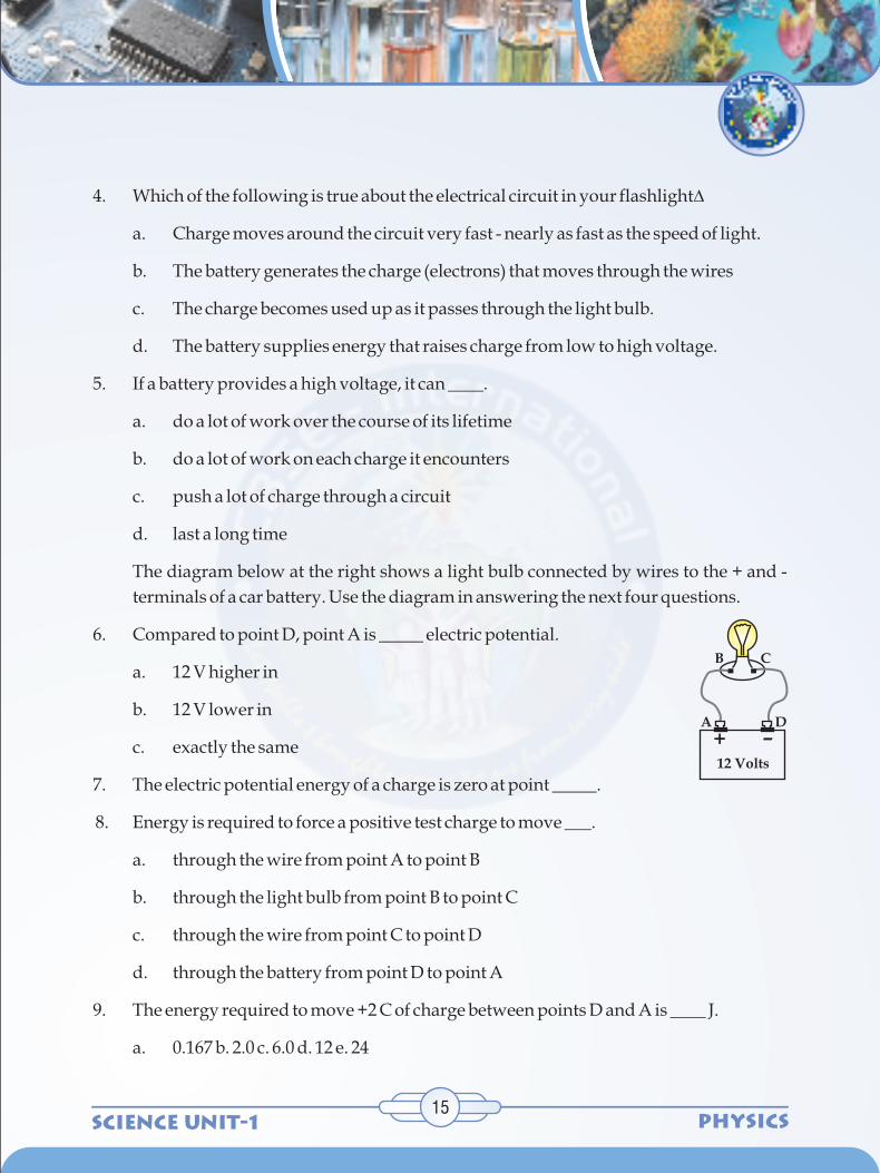
4. Which of the following is true about the electrical circuit in your flashlight?
a. Charge moves around the circuit very fast - nearly as fast as the speed of light.
b. The battery generates the charge (electrons) that moves through the wires
c. The charge becomes used up as it passes through the light bulb.
d. The battery supplies energy that raises charge from low to high voltage.
5. If a battery provides a high voltage, it can ____.
a. do a lot of work over the course of its lifetime
b. do a lot of work on each charge it encounters
c. push a lot of charge through a circuit
d. last a long time
The diagram below at the right shows a light bulb connected by wires to the + and -
terminals of a car battery. Use the diagram in answering the next four questions.
6. Compared to point D, point A is _____ electric potential.
a. 12 V higher in
b. 12 V lower in
c. exactly the same
7. The electric potential energy of a charge is zero at point _____.
8. Energy is required to force a positive test charge to move ___.
a. through the wire from point A to point B
b. through the light bulb from point B to point C
c. through the wire from point C to point D
d. through the battery from point D to point A
9. The energy required to move +2 C of charge between points D and A is ____ J.
a. 0.167 b. 2.0 c. 6.0 d. 12 e. 24
+ –12 Volts
DA
B C

SCIENCE UNIT-1PHYSICS
10. The following circuit consists of a dry cell and a light bulb. Use >, <, and = symbols to
compare the electric potential at A to B and at C to D. Indicate whether the devices add
energy to or remove energy from the charge.
11. Use your understanding of the mathematical relationship between work, potential
energy, charge and electric potential difference to complete the following statements:
a. A 9-volt battery will increase the potential energy of 1 coulomb of charge by ____
joules.
b. A 9-volt battery will increase the potential energy of 2 coulombs of charge by
____ joules.
c. A 9-volt battery will increase the potential energy of 0.5 coulombs of charge by
____ joules.
d. A ___-volt battery will increase the potential energy of 3 coulombs of charge by
18 joules.
e. A ___-volt battery will increase the potential energy of 2 coulombs of charge by 3
joules.
f. A 1.5-volt battery will increase the
potential energy of ____ coulombs of
charge by 0.75 joules.
g. A 12-volt battery will increase the
potential energy of ____ coulombs of
charge by 6 joules.
16
+B
AC
D
–
+Add or RemoveEnegrgy?
Add or RemoveEnegrgy?
Add or RemoveEnegrgy?
V _____VA B
(>, < or =)
V _____VC D
(>, < or =)
V _____VB D
(>, < or =)
Battery
+ + + + + ++ + + + + +
– – – – – –– – – – – –
E
High Potential
Low Potential

SCIENCE UNIT-1 PHYSICS17
2. Electric Circuit
Activity 2.1
Electric potential is the amount of electric potential energy per unit of charge that
would be possessed by a charged object if placed within an electric field at a given
location. Electric potential difference is simply the difference in electric potential
between two different locations within an electric field.
Let us now understand the meaning of an electric circuit. In an electric circuit, charges
must continually flow through a complete loop, returning to their original position
and cycling through again. If there were a means of moving positive charge from the
negative plate back up onto the positive plate, then the movement of positive charge
downward through the charge pipe (i.e., the wire) would occur continuously. In such
a case, a circuit or loop would be established.
Students will be able to
Illustrate the necessity of a closed conducting path for the flow of charges.
Observe the effect of connecting and disconnecting a wire.
The teacher may provide the students with
1. a battery pack(two to three cells)
2. a torch bulb
3. a few pieces of connecting wires
4. a switch
The students may be asked to connect the components and observe that when all
connections are made to the battery pack, the light bulb lights. In fact, the lighting of
the bulb occurs immediately after the final connection is made. There is no
perceivable time delay between when the last connection is made and when the light
bulb is perceived to light up.
The fact that the light bulb lights and remains lit is evidence that charge is flowing
through the light bulb filament and that an electric circuit has been established. A
Learning Objectives:

SCIENCE UNIT-1PHYSICS
circuit is simply a closed loop through which charges can continuously move. To
demonstrate that charges are not only moving through the light bulb filament but also
through the wires connecting the battery pack and the light bulb, a variation on the
above activity is made. A compass is placed beneath the wire at any location such that
its needle is placed in alignment with the wire. Once the final connection is made to
the battery pack, the light bulb lights and the compass needle deflects. The needle
serves as a detector of moving charges within the wire. When it deflects, charges are
moving through the wire. And if the wire is disconnected at the battery pack, the light
bulb is no longer lit and the compass needle returns to its original orientation. When
the light bulb lights, charge is moving through the electrochemical cells of the battery,
the wires and the light bulb filaments; the compass needle detects the movement of
this charge. It can be said that there is a current - a flow of charge within the circuit.
The electric circuit demonstrated by the combination of battery, light bulb and wires
consists of two distinct parts: the internal circuit and the external circuit. The part of
the circuit containing electrochemical cells of the battery is the internal circuit. The
part of the circuit where charge is moving outside the battery pack through the wires
and the light bulb is the external circuit.
After reading this section students will be able to do the following:
Explain what circuit diagrams are used for.
Identify what the symbols in the circuit diagrams stand for.
Circuit diagrams are a pictorial way of showing circuits. Electricians and engineers
draw circuit diagrams to help them design the actual circuits. Here is an example
circuit diagram.
ACTIVITY 2.2
2
2
CIRCUIT DIAGRAMS
18
V
A

SCIENCE UNIT-1 PHYSICS19
The important thing to note on this diagram is what different symbols stand for. We
see that there are straight lines that connect each of the symbols together. These lines
represent a wire.
represents an Ammeter.
represents a Voltmeter.
represents the resistor.
represents a switch.
represents a battery.
represents a light bulb.
1. Circuit diagrams are used to show how all the components connect together to make a
circuit.
Example 1:
Three Dry cells are placed in a battery pack to power a circuit containing three light
bulbs connected as shown. We can then draw its circuit diagram by using the
schematic symbols shown alongside.
Review
V
A
Drawing of Circuit Schematic Diagram of Circuit

SCIENCE UNIT-1PHYSICS
Example 2:
Three D-cells are placed in a battery pack to power a circuit containing three light
bulbs.
Using the verbal description, one can acquire a mental picture of the circuit being
described. But this time, the connections of light bulbs is done in a manner such that
there is a point on the circuit where the wires branch off from each other. The
branching location is referred to as a node. Each light bulb is placed in its own
separate branch. These branch wires eventually connect to each other to form a
second node. A single wire is used to connect this second node to the negative
terminal of the battery.
1. Use circuit symbols to construct schematic diagrams for the following circuits:
a. A single cell, light bulb and switch are placed together in a circuit such that the
switch can be opened and closed to turn the light bulb on.
b. A three-pack of D-cells is placed in a circuit to power a flashlight bulb.
Worksheet 2
Check Your Understanding
20
Schematic Diagram of CircuitDrawing of Circuit
c. d.

SCIENCE UNIT-1 PHYSICS21
2. Use the concept of conventional current to draw an unbroken line on the schematic
diagram at the right that indicates the direction of the conventional current. Place an
arrowhead on your unbroken line.
3. If an electric circuit could be compared to a water circuit at a water park, then the ...
... battery would be analogous to the ____.
... positive terminal of the battery would be analogous to the ____.
... current would be analogous to the ____.
... charge would be analogous to the ____.
... electric potential difference would be analogous to the ____.
Choices:
A. water pressure B. volume of water flowing down slide per minute
C. water D. bottom of the slide
E. water pump F. top of the slide
4. Utilize your understanding of the requirements of an electric circuit to state whether
charge would flow through the following arrangements of cells, bulbs, wires and
switches. If there is no charge flow, then explain why not.
a. b.
Charge Flow: Yes or No? Charge Flow: Yes or No?
Explanation: Explanation:
+
–
+
–

SCIENCE UNIT-1PHYSICS
c. d.
Charge Flow: Yes or No? Charge Flow: Yes or No?
Explanation: Explanation:
5. The diagram shows a light bulb connected to a 12-V car battery. The + and - terminals
are shown.
a. As a + charge moves through the battery from D to A, it ________ (gains, loses)
potential energy and ________ (gains, loses) electric potential. The point of
highest energy within a battery is the ______ (+, -) terminal.
b. As a + charge moves through the external circuit from A to D, it ________ (gains,
loses) potential energy and ________ (gains, loses) electric potential. The point
of highest energy within the external circuit is closest to the ______ (+, -)
terminal.
c. Use >, <, and = signs to compare the electric potential (V) at the four points of the
circuit.
V ______ V ______ V ______ VA B C D
6. In the movie Tango and Cash, Kurt Russell and Sylvester Stallone escape from a
prison by jumping off the top of a tall wall through the air and onto a high-voltage
power line. Before the jump, Stallone objects to the idea, telling Russell "We're going
22
+
–+–
+–
+ –12 Volts
DA
B C

SCIENCE UNIT-1 PHYSICS23
to fry." Russell responds with "You didn't take high school Physics, did you? As long
as you're only touching one wire and your feet aren't touching the ground, you don't
get electrocuted." Is this a correct statement?
If the two requirements of an electric circuit are met, then charge will flow through the
external circuit. It is said that there is a current - a flow of charge. Using the word
current in this context is to simply use it to say that something is happening in the
wires - charge is moving. Yet current is a physical quantity that can be measured and
expressed numerically. As a physical quantity, current is the rate at which charge
flows past a point on a circuit. The current in a circuit can be determined if the
quantity of charge Q passing through a cross section of a wire in a time t can be
measured. The current is simply the ratio of the quantity of charge and time.
Current is a rate quantity and is expressed mathematically as
Current = I =
Note that the equation above uses the symbol I to represent the quantity current.
The standard metric unit for current is the ampere. It is often shortened to Amp and is
abbreviated by the unit symbol A. A current of 1 ampere means that there is 1
coulomb of charge passing through a cross section of a wire every 1 second.
1 ampere = 1 coulomb / 1 second
3. Electric Current
Qt
+
–
I
I
I
IElectric current in the external
circuit is directed from thepositive to the negative terminal.

SCIENCE UNIT-1PHYSICS
To test your understanding, determine the current for the following two situations.
24
A 2 mm long cross section of wire is
isolated and 20 C of charge is determined
to pass through it in 40
A 1 mm long cross section of wire is
isolated and 2 C of charge is determined
to pass through it in 0.5
3.1 Conventional Current Direction
The particles that carry charge through wires in a circuit are mobile electrons. The
electric field direction within a circuit is by definition the direction that positive test
charges are pushed. Thus, these negatively charged electrons move in the direction
opposite the electric field. But while electrons are the charge carriers in metal wires,
the charge carriers in other circuits can be positive charges, negative charges or both.
In fact, the charge carriers in semiconductors, street lamps and fluorescent lamps are
simultaneously both positive and negative charges traveling in opposite directions.
Ben Franklin, who conducted extensive scientific studies in both static and current
electricity, envisioned positive charges as the carriers of charge. As such, an early
convention for the direction of an electric current was established to be in the
direction that positive charges would move. The convention has stuck and is still used
today. The direction of an electric current is by convention the direction in which a
positive charge would move. Thus, the current in the external circuit is directed away
from the positive terminal and toward the negative terminal of the battery. Electrons
would actually move through the wires in the opposite direction.
2mm
20 C 20 C40 s
1mm
2 C 2 C0.5 s
I = _____ ampere I = _____ ampere

SCIENCE UNIT-1 PHYSICS25
Worksheet 3
Check Your Understanding
1. A current is said to exist whenever _____.
a. a wire is charged
b. a battery is present
c. electric charges are unbalanced
d. electric charges move in a loop
2. Current has a direction. By convention, current is in the direction that ___.
a. + charges move
b. - electrons move
c. + electrons move
d zero charge neutrons move
3. The diagram below depicts a conducting wire. Two cross-sectional areas are located
50 cm apart. Every 2.0 seconds, 10 C of charge flow through each of these areas. The
current in this wire is ____ A.
a. 0.10 b. 0.25 c. 0.50
d. 1.0 e. 5.0 f. 20g. 10
h. 40 i. none of these
50cm
10 C 10 C2s

SCIENCE UNIT-1PHYSICS26
4. Look at the diagram below and complete the following statements:
a. When a current of one ampere How through the bulb located between A and B,
there would be a flow of charge at the rate of _______ coulomb per second
through this bulb.
b. When a charge of 8 C flows past any point along the circuit in 2 seconds, the
current is ________ A.
c. If 5 C of charge flow past point A (diagram at right) in 10 seconds, then the
current is _________ A.
d. If the current at point D is 2.0 A, then _______ C of charge flow past point D in 10
seconds.
e. If 12 C of charge flow past point A in 3 seconds, then 8 C of charge will flow past
point E in ________ seconds.
f. True or False:
The current at point E is considerably less than the current at point A since
charge is being used up in the light bulbs.
An electrochemical cell supplies energy to move a
charge from its low energy, low potential terminal to the
high energy, high potential terminal. In this sense, the
cell supplies the energy to establish an electric potential
difference across the two ends of the external circuit.
Charge will then flow through the external circuit in the
4. Journey of a Typical Electron

SCIENCE UNIT-1 PHYSICS27
same manner that water will flow from an elevated position to a low position. It is the
difference in potential that causes this flow.
In the wires of electric circuits, an electron is the
actual charge carrier. An electron's path through
the external circuit is far from being a straight path.
An electron's journey through a circuit can be
described as a zigzag path that results from
countless collisions with the atoms of the
conducting wire. Each collision results in the alteration of the path, thus leading to a
zigzag type motion. While the electric potential difference across the two ends of a
circuit encourages the flow of charge, it is the collisions of charge carriers with atoms
of the wire that discourages the flow of charge. Different types of atoms offer a
different degree of hindrance to the flow of the charge carriers that pass through it.
In all cases, the collisions of charge carriers in an electric circuit with the conducting
elements of that circuit result in a loss of energy. While most the electrical energy
possessed by a charge carrier is lost when it passes through an electrical device (often
referred to as the load), even the wires of the circuit themselves act to remove energy
from a charge. It is because of this energy loss in the load and in the wires themselves
that the electric potential of a charge carrier is decreased as it traverses the external
circuit. The electric energy supplied by the electrochemical cells becomes entirely
used up in the external circuit.
In an electric circuit with several electrical devices, there may be multiple stepwise
losses of electric potential as the charge traverses the circuit. Regardless of the way in
which the devices are wired, the total loss of electric potential of a single charge as it
passes through the external circuit is equal to the gain in electric potential that it
experiences in the battery.
The journey of an electron through an external circuit involves a long and slow zigzag
path that is characterized by several successive losses in electric potential. Each loss of
potential is referred to as a voltage drop. Accompanying this voltage drop is a voltage
boost occurring within the internal circuit - for instance, within the electrochemical
cell.

SCIENCE UNIT-1PHYSICS
4.1 Resistance
An electron traveling through the wires and loads of the external circuit encounters
resistance. Resistance is the hindrance to the flow of charge. For an electron, the
journey from terminal to terminal is not a direct route. Rather, it is a zigzag path that
results from countless collisions with fixed atoms within the conducting material.
The electrons encounter resistance - a hindrance to their movement. While the electric
potential difference established between the two terminals encourages the
movement of charge, it is resistance that discourages it. The rate at which charge flows
from terminal to terminal is the result of the combined affect of these two quantities.
Variables Affecting Electrical Resistance
The flow of charge through wires is often compared to the flow of water through
pipes. The resistance to the flow of charge in an electric circuit is analogous to the
frictional affects between water and the pipe surfaces as well as the resistance offered
by obstacles that are present in its path. It is this resistance that hinders the water flow
and reduces both its flow rate and its drift speed. Like the resistance to water flow, the
total amount of resistance to charge flow within a wire of an electric circuit is affected
by some clearly identifiable variables.
Learners can perform this activity on their own to understand the effect of length and
area of cross section of a wire on its resistance.
http://www.hyperstaffs.info/work/physics/child/index.html interactive website
First, the total length of the wires will affect the amount of resistance. The longer the
wire, the more will be its resistance. There is a direct relationship between the amount
of resistance encountered by charge and the length of wire it must traverse. After all, if
resistance occurs as the result of collisions between charge carriers and the atoms of
the wire, then there is likely to be more collisions in a longer wire. More collisions
mean more resistance.
Second, the cross-sectional area of the wires will affect the amount of resistance.
Wider wires have a greater cross-sectional area. Water will flow through a wider pipe
at a higher rate than it will flow through a narrow pipe. This can be attributed to the
lower amount of resistance that is present in the wider pipe
Activity 4 [on the Net]
28

SCIENCE UNIT-1 PHYSICS29
A third variable that is known to affect the resistance to charge flow is the material
that a wire is made of. Not all materials are created equal in terms of their conductive
ability. Some materials are better conductors than others and offer less resistance to
the flow of charge. Silver is one of the best conductors but is never used in wires of
household circuits due to its cost. Copper and aluminum are among the least
expensive materials with suitable conducting ability to permit their use in wires of
household circuits. The conducting ability of a material is often indicated by its
resistivity. The resistivity of a material is dependent upon the material's electronic
structure and its temperature. For most (but not all) materials, resistivity increases
with increasing temperature. The table below lists resistivity values for various
materials at temperatures of 20 degrees Celsius.
-8Silver 1.59 x 10
-8Copper 1.7 x 10
-8Gold 2.4 x 10
-8Aluminum 2.8 x 10
-8Tungsten 5.6 x 10
-8Iron 10 x 10
-8Platinum 11 x 10
-8Lead 22 x 10
-8Nichrome 150 x 10
5Carbon 3.5 x 10
7 11Polystyrene 10 - 10
8 9Polyethylene 10 - 10
10 14Glass 10 - 10
13Hard Rubber 10
Material Resistivity
(ohm•meter)

SCIENCE UNIT-1PHYSICS
4.2 Mathematical Expression of Resistance
Check Your Understanding
Resistance is a numerical quantity that can be measured and expressed
mathematically. The standard metric unit for resistance is the ohm, represented by
the Greek letter omega - Ù . An electrical device having a resistance of 5 ohms would
be represented as R = 5 Ù. The equation representing the dependency of the resistance
(R) of a wire shaped conductor upon the variables that affect it is
where L represents the length of the wire (in meters), A represents the cross-sectional
area of the wire (in meters2), and represents the resistivity of the material (in
ohmometer). This equation shows that the resistance of a wire is directly proportional
to the length of the wire and inversely proportional to the cross-sectional area of the
wire. Knowing the length, cross-sectional area and the material that a wire is made of
(and thus, its resistivity) one can determine the resistance of the wire.
1. Household circuits are often wired with two different thickness of wires: 12-gauge
and 14-gauge. The 12-gauge wire has a diameter of 2.1 mm while the 14-gauge wire
has a diameter of 1.8 mm. Thus, 12-gauge wire has a wider cross section than 14-
gauge wire. A 20-Amp circuit used for wall receptacles should be wired using 12-
gauge wire and a 15-Amp circuit used for lighting and fan circuits should be wired
using 14-gauge wire. Explain the physics behind such an electrical code.
2. Based on the information stated in the above question, explain the risk involved in
using 14-gauge wire in a circuit that will be used to power an 16-ampere power saw.
3. Determine the resistance of a 1 Km length of 12-gauge copper wire of diameter 2.1
mm.
4. Two wires - A and B - with circular cross-sections have identical lengths and are made
of the same material. Yet, wire A has four times the resistance of wire B. How many
times greater is the diameter of wire B than wire A?
Worksheet 4
30
R = p LA

SCIENCE UNIT-1 PHYSICS31
Student Teacher Material
5. Ohm's Law
Ohm's Law gives the relation between the potential difference across the two
terminals of a conductor and the current flowing through it.
It states that the potential difference across the two terminals of a conductor is directly
proportional to the current passing through it.
V∞ I
V = RI where R(resistance) is the proportionality constant
A very well known equation which pervades the study of electric circuits, is the
equation
V = I • R
In words, the electric potential difference between two points on a circuit (V) is
equivalent to the product of the current between those two points (I) and the total
resistance of all electrical devices present between those two points (R). Often
referred to as the Ohm's law equation, this equation is a powerful predictor of the
relationship between potential difference, current and resistance.
Ohm's Law as a Predictor of Current
The Ohm's law equation can be rearranged and expressed as
This equation can be used for, calculating the current if the electric potential
difference and the resistance are known. This equation indicates the two variables
that would affect the amount of current in a circuit. The current in a circuit is directly
proportional to the electric potential difference impressed across its ends and
inversely proportional to the total resistance offered by the external circuit. The
greater the battery voltage (i.e., electric potential difference), the greater the current.
And the greater the resistance, the less the current. The table below illustrates this
relationship both qualitatively and quantitatively for several circuits with varying
battery voltages and resistances.
I = VR

SCIENCE UNIT-1PHYSICS32
Circuit Battery Total Current
Diagram Voltage Resistance (Amps)
(V) (? )
1. 1.5 V 3 ? 0.50 Amp
2. 3.0 V 3 ? 1 Amp
3. 1.5 V 6 ? 0.25 Amp
4. 3.0 V 6 ? 0.5 Amp
Because the current in a circuit is affected by the resistance, resistors are often used in
the circuits of electrical appliances to affect the amount of current that is present in its
various components. By increasing or decreasing the amount of resistance in a
particular branch of the circuit, one can increase or decrease the amount of current in
that branch. Kitchen appliances such as electric mixers and light dimmer switches
operate by altering the current at the load by increasing or decreasing the resistance of
the circuit.
The diagram below depicts a couple of circuits containing a voltage source (battery
pack), a resistor (light bulb) and an ammeter (for measuring current). In which circuit
does the light bulb have the greatest resistance?

SCIENCE UNIT-1 PHYSICS33
Ohm's law can be verified in the laboratory using a resistor, a battery pack, an
ammeter, and a voltmeter. An ammeter is a device used to measure the current at a
given location. A voltmeter is a device that can be touched to two points on a circuit to
determine the electric potential difference across those points. By altering the number
of cells in the battery pack, the electric potential difference across the external circuit
can be varied. The voltmeter can be used to determine this potential difference and
the ammeter can be used to determine the current associated with this ?V. The process
can be repeated several times to yield a set of I- ?V data. A plot of I versus ?V is seen to
be a straight line with a slope that is equivalent to the reciprocal of the resistance of the
resistor. Ohm's law equation thus gets checked.
Verification of Ohm's Law
The learners will be able
to perform an experiment to verify Ohm's Law
to practice constructing electric circuits
to practice using an ammeter and a voltmeter
The teacher may give the instructions before hand.
In the lab, you will construct a simple circuit using a single known resistance, R. Then you
will use an ammeter to measure the current, I, through the resistance and a voltmeter to
measure the potential difference, V, across the resistance. With this data, you can check the
validity of Ohm's Law (V = IR) in the circuit.
1.5 or 2 V power supply switch resistor
0-1 A ammeter 0-3 V voltmeter connecting wires
Activity 5
2
2
2
Learning Objectives:
Discussion:
Equipment:

SCIENCE UNIT-1PHYSICS
Procedure:
IMPORTANT: In this lab you will use ONLY the "COMMON" and "1.5 or 2 V DC"
terminals on the power supply. Connecting the circuit to any other terminals will certainly
result in destruction of equipment and might well be risky for the user.
Set up the circuit shown in the diagram shown using the resistor of known value.
a. Screw one end of the resistor to the 1.5/2 VDC terminal of the power supply.
b. Using one of the connecting wires, connect the other end of the resistor to the red
terminal of the ammeter.
c. Be sure that the switch is open.
d. Using another wire, connect the black terminal of the ammeter to either side of
the switch. Notice that when the switch is closed, current will flow through the
resistor, the ammeter, and the switch in this circuit.
e. Connect the other switch terminal to the COMMON terminal on the power
supply using a wire.
f. Connect a wire from the red terminal of the voltmeter to the 1.5/2 VDC terminal
of the power supply.
g. Connect a wire from the black terminal of the voltmeter to the red terminal of the
ammeter.
After the completion of the circuit carefully read the voltage across the resistor and the
current through the resistor and record the readings in a tabular form. Repeat the
experiment for different values of voltage.
34
1.5 or 2 V DC

SCIENCE UNIT-1 PHYSICS35
Results:
Check Your Understanding
For each set of values of the voltage drop and the current, the calculated resistance remains
constant, hence verifying Ohm's law.
1. Which of the following will cause the current through an electrical circuit to decrease?
Choose all that apply.
a. decrease the voltage
b. decrease the resistance
c. increase the voltage
d. increase the resistance
2. A certain electrical circuit contains a battery with three cells, wires and a light bulb.
Which of the following would cause the bulb to shine less brightly? Choose all that
apply.
a. increase the voltage of the battery by adding another cell
b. decrease the voltage of the battery ( by removing a cell)
c. decrease the resistance of the circuit
d. increase the resistance of the circuit
3. You have likely been warned to avoid contact with electrical appliances or even
electrical outlets when your hands are wet. Such contact is more dangerous when
your hands are wet (vs. dry) because wet hands cause ____.
a. the voltage of the circuit to be higher
b. the voltage of the circuit to be lower
c. your resistance to be higher
d. your resistance to be lower
Worksheet 5

SCIENCE UNIT-1PHYSICS
4. If the resistance of a circuit were increased three times, then the current through the
circuit would be ____.
a. one-third as much
b. three times as much
c. unchanged
5. If the voltage across a circuit is increased four times, then the current through the
circuit would be ____.
a. one-fourth as much
b. four times as much
c. unchanged
6. A circuit is wired with a power supply, a resistor and an ammeter (for measuring
current). The ammeter reads a current of 24 mA (milliamps). Determine the new
current if the voltage of the power supply was ...
a. ... increased by a factor of 2 and the resistance was held constant.
b. ... increased by a factor of 3 and the resistance was held constant.
c. ... decreased by a factor of 2 and the resistance was held constant.
d. ... held constant and the resistance was increased by a factor of 2.
e. ... held constant and the resistance was increased by a factor of 4.
f. ... held constant and the resistance was decreased by a factor of 2.
g. ... increased by a factor of 2 and the resistance was increased by a factor of 2.
h. ... increased by a factor of 3 and the resistance was decreased by a factor of 2.
i. ... decreased by a factor of 2 and the resistance was increased by a factor of 2.
7. Use Ohm's law equation to provide numerical answers to the following questions:
a. An electrical device with a resistance of 3.0 ? will allow a current of 4.0 amps to
flow through it if a voltage drop of ________ Volts is impressed across the
device.
36

SCIENCE UNIT-1 PHYSICS37
b. When a voltage of 120 V is maintained across an electric heater, a current of 10.0
amps will flow through the heater if the resistance is ________ ? .
c. A flashlight that is powered by 3 Volts and uses a bulb with a resistance of 60 ?
will have a current of ________ Amps.
8. Use Ohm's law equation to determine the missing values in the following circuits.
9. Refer to question 8 above. In the circuits of diagrams A and B, what method was used
to control the current in the circuits? And in the circuits of diagrams C and D, what
method was used to control the current in the circuits?

SCIENCE UNIT-1PHYSICS
6. THE SERIES CIRCUIT
ACTIVITY 6
2
2
2
After reading this section, students will be able to do the following:
Define a series circuit, and list the components needed to make it.
Construct a simple and complex series circuit.
Define what a load is.
Try building this simple series circuit
The circuit we see above is something called a series circuit. This is called a series circuit
because there is only one path for the electrons to take between any two points in this
circuit. In other words, the components, which are the battery, the switch, the ammeter,
and light, are all in "series" with each other.
Notice that when we close the switch to complete the electrical circuit, the electrons start
moving and the ammeter indicates that there is current flowing in this circuit. Also notice
that the light bulb begins to glow.
The light bulb is considered a load in this circuit. We might think of a load as anything that
is using the energy that is being delivered by the electric current in a circuit. It could be
anything from a light bulb to a computer to a washing machine and so on.
Try building a series circuit with resistors
Let's build another series circuit, but this time we will use some resistors instead of a light
bulb. Resistors are components that are used to control that amount of current flowing in a
circuit. If there are no resistors to control the flow of electrical current, too much current
may flow through the circuit and damage its components or wires.
Load defined
38

SCIENCE UNIT-1 PHYSICS39
Characteristics of 'SERIES CIRCUITS’
Review
6.1 SERIES CIRCUIT CALCULATIONS
In a Series Circuit the charge carriers [electrons] have only one path to flow. Hence the
electrons must go through each component to complete the flow. When the loads are
placed in series, we would observe the following
1. An open in the circuit will disable the entire circuit.
2. The voltage gets divides (shared) between the loads.
3. The current flow is the same throughout the circuit.
4. The resistance of each load can be different.
1. When all the components are in line with each other and the wires, a series circuit is
formed.
2. A load is any device in a circuit that is using the energy that the electron current is
delivering to it.
If, for example, two or more lamps
(resistances R and R , etc.) are connected in a 1 2
circuit as follows, there is only one route that
the current can take. This type of connection
is called a series connection. The value of
current I is always the same at any point in a
series circuit.
The combined resistance RO in this circuit is
equal to the sum of individual resistance R 1

SCIENCE UNIT-1PHYSICS
and R . In other words: The total resistance(RO) is equal to the sum of all resistances 2
(R + R + R + .......)1 2 3
R = R + R0 1 2
Therefore, the strength of current (I) flowing in the circuit can be found as follows:
Resistance R0 (a combination of resistances R1 and R2, which are connected in series
in the circuit as illustrated) and current I flowing in this circuit can be determined as
follows:
40

SCIENCE UNIT-1 PHYSICS41
7. THE PARALLEL CIRCUIT
ACTIVITY 7
2
2
2
After reading this section, students will be able to do the following:
Define a parallel circuit and explain how it compares to a series circuit.
Construct a parallel circuit.
Explain what a voltmeter does and how it is different from an ammeter.
Like the series circuit, parallel circuits also contain a voltage (current) source as well as
wires and other components. The main difference between a series circuit and a parallel
circuit is in the way the components are connected. In a parallel circuit the electricity has
several paths that it can travel.
Try building this simple parallel circuit
Notice that when you closed the switch, the electrons flowed through both loads at the
same time. In our series circuit, all the electrons flowed through all the components in
order. With the parallel circuit, some electrons go through one load and some go through
the other load, all at the same time. At point A, the total current splits up and takes different
paths before the circuit joins back together again at point B.
A parallel circuit exists whenever two or more components are connected between the
same two points. Those two points in this circuit are points A and B. Both resistors connect
to both points A and B.
Each parallel path is called a branch of the parallel circuit. We will now try building this
parallel circuit, including a voltmeter

SCIENCE UNIT-1PHYSICS
The parallel circuit shown here, contains 3 branches (two resistors and a voltmeter), which
means the electron current goes through all three branches at the same time. We put a
voltmeter on this second circuit to show an important fact. In the last 4 circuits we made, we
included an ammeter into them. Ammeters must always be placed in series in a circuit,
otherwise they will not work. The voltmeter we added in the last circuit has a different
requirement in order to work. Voltmeters must be placed in parallel with the circuit in
order to work. This is because voltage meters measure the difference in potential from one
point to another.
A Parallel Circuit has multiple paths or branches to ground. Therefore:
1. In the event of an open in the circuit in one of the branches, current will continue to
flow through the remaining.
2. Each branch receives the same source voltage.
3. Current flow through each branch can be different.
4. The resistance of each branch can be different.
CHARACTERISTICS OF PARALLEL CIRCUITS
42

SCIENCE UNIT-1 PHYSICS43
Review
7.1 PARALLEL CIRCUIT CALCULATION
1. When some of the components are connected parallel with each other, they form a
parallel circuit.
2. A voltmeter must be wired in parallel in a circuit in order to measure the difference in
potential from one point to another.
In parallel connection, two or more resistances (R1, R2, etc.) are connected in a circuit
as follows, with one end of each resistance connected to the high (positive) side of the
circuit, and one end connected to the low (negative) side. Full battery voltage is
applied to all resistances within a circuit having a parallel connection.
Resistance R (a combination of resistances R1 and R2) in a parallel connection can be 0
determined as follows:
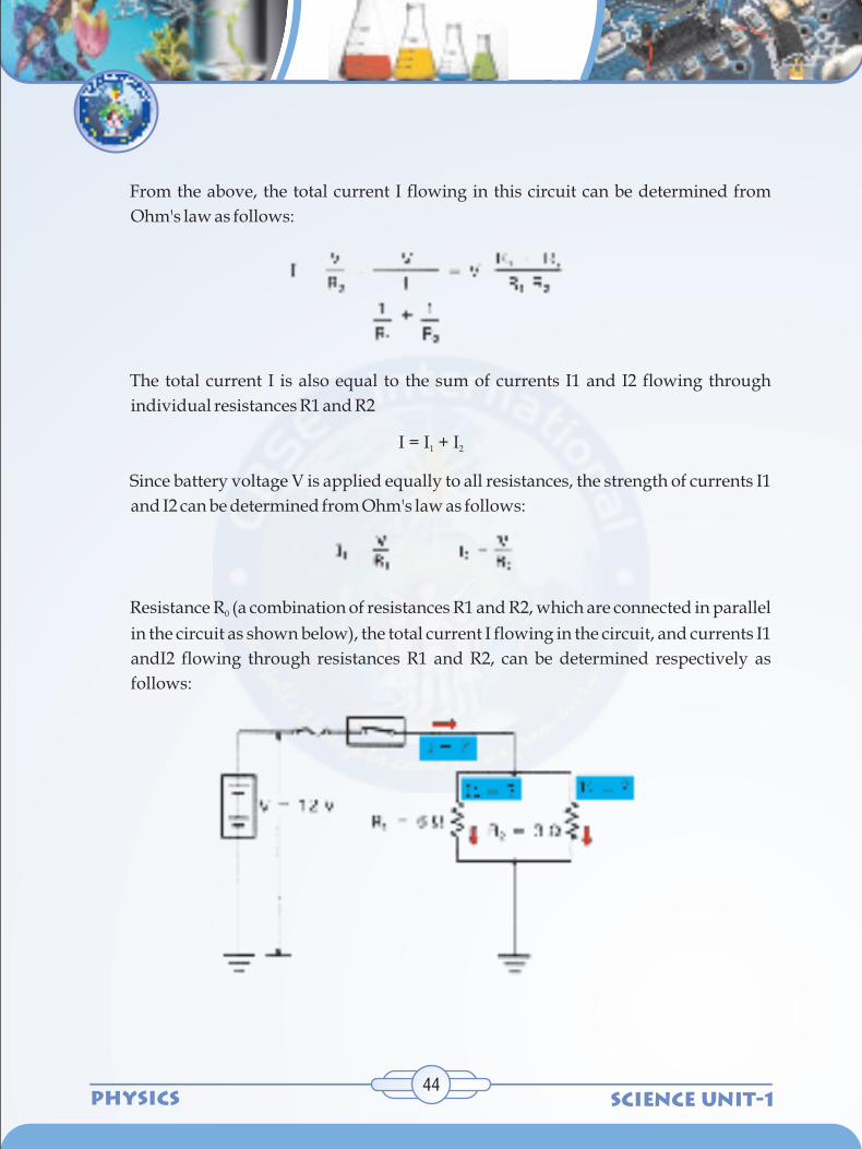
SCIENCE UNIT-1PHYSICS
From the above, the total current I flowing in this circuit can be determined from
Ohm's law as follows:
The total current I is also equal to the sum of currents I1 and I2 flowing through
individual resistances R1 and R2
I = I + I1 2
Since battery voltage V is applied equally to all resistances, the strength of currents I1
and I2 can be determined from Ohm's law as follows:
Resistance R (a combination of resistances R1 and R2, which are connected in parallel 0
in the circuit as shown below), the total current I flowing in the circuit, and currents I1
andI2 flowing through resistances R1 and R2, can be determined respectively as
follows:
44

SCIENCE UNIT-1 PHYSICS45
8. THE SERIES/PARALLEL CIRCUIT
ACTIVITY 8
2
2
After reading this section, students will be able to do the following:
Explain what a series/parallel circuit is and what components are needed to
complete it.
Construct a series/parallel circuit.
When we have a circuit in which some of the components are in series and others are in
parallel, we have a series/parallel circuit.
Try building a series/parallel circuit

SCIENCE UNIT-1PHYSICS
Notice in this series/parallel circuit that the resistors R1, the switch, the battery, and the
ammeter are in series with each other while resistors R2 and R3 are in parallel with each
other. We might also say that the R2/R3 combination is in series with the rest of the
components in this circuit.
By applying Ohm's law, to a given series or parallel or a combination of the two circuits, we
can calculate the current flowing at any point in such circuits.
The combined resistance R02 in this series-parallel connection can be determined in the
following order:
a. Determine combined resistance R01, which is a combination of resistances R2
and R3 connected in parallel.
b. Then, determine resistance R02, which is a combination of resistance R1 and
combined resistance R01 connected in series.
Total current I flowing in the circuit can be determined from Ohm's law as follows:
The voltage applied to R2 and R3 can be found by the following formula:
Currents I1, I2 and I flowing through resistances R1, R2 and R3 in the series-parallel
connection, as shown below, can be determined as follows:
8.1 SERIES PARALLEL CALCULATIONS
46

SCIENCE UNIT-1 PHYSICS47
NOTE: The Powerpoint Presentation attached here can be used for recapitulating the
concepts dealt till this section of the chapter.

SCIENCE UNIT-1PHYSICS
9. Heating effect of current
ACTIVITY 9
2
2
2
2
2
2
Class experiment
Apparatus and materials
Safety
Procedure
Illustrates two ideas: electric current causes heating effect; temperature affects the
resistance of a wire.
For each student group:
Cells, 1.5 V, with holders, 3
Lamp with holder
Crocodile clips, 2
Ammeter (0 - 1 amp), DC
Leads, 4 mm, 5
Eureka wire 34 SWG, 15 cm length
Modern dry cell construction uses a steel can connected to the positive (raised) contact. The
negative connection is the centre of the base with an annular ring of insulator between it
and the can
48

SCIENCE UNIT-1 PHYSICS49
a Set up a series circuit of three cells and a lamp. Include two crocodile clips in the
circuit.
b Wind the length of bare Eureka wire into a coil (using, say, a pencil). Clamp the ends
of the wire into the two crocodile clips. (Make sure that the turns of wire do not touch
each other.)
c Stand back! Carefully, hold your hand above the wire coil. Can you feel hot air rising?
1 When an electric current passes through a metal, it warms up. The open coil of wire
will be warm to the touch. Blowing on the wire will reduce its temperature and the
lamp will glow brighter. Try using an electronics freezer spray to reduce the
temperature of the coil even more and the lamp will glow brighter still.
2 It is important that the coils must not touch each other, or the coil will become a short
circuit.
3 This experiment can be demonstrated in order to explain how a filament lamp works.
The filament is just a short piece of wire which gets so hot that it glows red for low
currents, becoming whiter as the current increases staying within its permitted [safe]
limits, of course.
4 Careful and observant students are likely to have noticed that when a circuit
consisting of a cell, a lamp and an ammeter is connected, the current is momentarily
greater when the connection is made, and then the current settles down to a steady
lower value. This is because the resistance of the cold wire is less than the resistance of
the hot wire.
Heating effect of electricity is one of the widely used effects in the world. When
electric current is passed through a conductor, it generates heat due to the resistance it
offers to the current flow. The work done in overcoming the resistance is generated as
heat. This is studied by James Prescott Joule and he enunciated various factors that
affect the heat generated. The heat produced by a heating element is directly
proportional to the square of the electric current (I) passing through the conductor,
directly proportional to the resistance (R) of the conductor, time (t) for which current
passes through the conductor. It is given by the expression H = I2Rt and is well known
as Joule's Law.
Teaching notes
9.1 Applications of 'Heating Effect of Current'

SCIENCE UNIT-1PHYSICS
Applications of the heating effect of electric current include appliances like electric
immersion water heater, electric iron box, etc. All of these have a heating element in it.
Heating elements are generally made of specific alloys like, nichrome, manganin,
constantan etc. A good heating element has high resistivity and high melting point.
An electric fuse is an example for the application of heating effect of electric current.
The rating of 3 A of an electric fuse implies the maximum current it can sustain is three
ampere.
Joule’s law of Heating
When some potential difference V is applied across a resistance R then the work done
by the electric field on charge q to flow through the circuit in time t will be
This work appears as thermal energy in the resistor.
Heat produced by the resistance R is quite often expressed in Calorie. Since 1 calorie =
4.2 J we have
The rate at which electrical energy is dissipated into other forms of energy is called
electric power i.e.
Units: It's S.I. unit is joule/sec or watt
Bigger S.I. units are KW, MW and horse power [HP], remember that 1 HP = 746 Watt
Rating values
On electrical appliances (Bulbs, Heater, Geyser … etc). wattage, voltage, … etc. are
printed. These are called its rating values. If suppose we have a bulb of 40 W, 220 V
then rated power (PR) = 40 W while rated voltage (VR) = 220 V.
10. Electric Power
50

SCIENCE UNIT-1 PHYSICS51
Resistance of electrical appliance
If variation of resistance with temperature is neglected then resistance of any
electrical appliance can be calculated from its rated power and rated voltage by using
Power consumed
An electrical appliance (Bulb, heater, … etc.) consume rated power (PR) only if
applied voltage (VA) is equal to rated voltage (VR) i.e. If VA = VR
So
So
Long distance power transmission
When power is transmitted through a power line of resistance R, power-loss will be
i2R
Now if the power P is transmitted at voltage V then P = VI, i.e.
i = (P / V)
So, Power loss
2Now as for a given power and line, P and R are constant. Hence Power loss ∞ (1/V )
So if power is transmitted at high voltage, power loss will be small and vice-versa.
This is why long distance power transmission is carried out at high voltage.
1. The price of electricity consumed is calculated on the basis of electrical energy
consumed and not on the basis of electrical power.
2. The unit joule for energy is very small. Hence a big practical unit is known as
kilowatt hour (KWH) or board of trade unit (B.T.U.) is used as the practical
commercial unit
10.1 Electricity Consumption
ZR
R
VR=
P

SCIENCE UNIT-1PHYSICS
3. 1 kWh or 1 commercial unit is the quantity of electrical energy which gets
dissipated in one hour in an electrical circuit when the electrical power in the
circuit is 1 kW thus .
4. A simple formulae to calculate the no. of consumed units is
Solved example 1: Two heater wires of equal length are first connected in series and
then in parallel. The ratio of heat produced in the two cases is
(A) 2 : 1 (B) 1 : 2 (C) 4 :1 (D) 1 : 4
Solution: (D) Power consumed means heat produced.
For constant potential difference Pconsumed = Heat
Solved example 2: A wire when connected to 220 V mains supply has power
dissipation P1. Now the wire is cut into two equal pieces which are connected in
parallel to the same supply. Power dissipation in this case is P2. Then P2 : P1 is
(A) 1 (B) 4 (C) 2 (D) 3
Solution: (B) When wire is cut into two equal parts then power dissipated by each
part is 2P1
So their parallel combination will dissipate power
P = 2P + 2P = 4P , which gives2 1 1 1
.
52

SCIENCE UNIT-1 PHYSICS53
POST CONTENT
Revision Worksheet 1
1. The main cause of resistance to the flow of charge within an electrical wire is _____.
a. mobile charge carriers collide with atoms of the resistor
b. mobile charge carriers have mass (possess inertia) which resists their motion
c. the electric field which causes charge flow diminishes with distance
d. charge is consumed or used up as it flows through the wire
2. Resistance is quantifiable - that is, it can be measured and calculated. The standard
metric unit usedto express the amount of electrical resistance is the ____.
a. Joule b. Watt c. Volt d. Ohm
3. For the following pairs of wire descriptions, choose the wire which has the greatest
resistance.Resistance to charge flow will be greatest in … . (Circle the best answer.)
a. … a wire which is thin … a wire which is thick
b. … a wire which is long … a wire which is short
c. … a wire which is made of copper … a wire which is made of plastic
d. … a wire which is made of copper … a wire which is made of silver
4. The rate at which charge flows through a circuit is ___________ to the resistance.
a. inversely related b. directly related c. not related
5. For the following pairs of circuit descriptions, choose the circuit which has the
greatest current.Given that all other factors are equal, the current will be greatest in a
circuit which has … .
a. … a high resistance … a low resistance
b. … wires which are long … wires which are short
c. … wires which are wide … wires which are thin
d. … 12-gauge wires (2.1 mm diameter) … 14-gauge wires (1.8 mm diameter)
e. … copper wiring … silver wiring

SCIENCE UNIT-1PHYSICS
6. Resistance is not the only variable which effects the current in an electric circuit. The
current is also affected by the electric potential difference (? V) applied across its
ends. The electric potential difference is simply the battery voltage. As the battery
voltage is increased, the current is _____________________ (increased, decreased).
7. A circuit is set up such that it has a current of 8.0 amps. What would be the new current
if
a. … the resistance (R) is increased by a factor of 2?
b. … the resistance (R) is increased by a factor of 4?
c. … the resistance (R) is decreased by a factor of 3?
d. … the battery voltage (V) is increased by a factor of 3?
e. … the battery voltage (V) is decreased by a factor of 2?
f. … the resistance (R) is increased by a factor of 2 and the battery voltage (V) is
decreased by a factor of 2?
g. … the resistance (R) is decreased by a factor of 4 and the battery voltage (V) is
increased by a factor of 3?
8. Express your understanding of the use of the I = V / R equation by filling in the
following blanks.
a. An electrical device with a resistance of 2.0 ? has an electric potential difference
of 6.0 V impressed across it; the current in the device is _____ amperes.
b. An electrical device with a resistance of 3.0 ? has an electric potential difference
of ______ V impressed across it; the current in the device is 4.0 amperes.
c. An electrical device with a resistance of _____ ? has an electric potential
difference of 120 V impressed across it; the current in the device is 6.0 amperes.
9. Resistors are electrical devices designed to have a specific resistance. They are
inserted in circuits to modify the actual current flowing through the circuit.
Which of the resistors in the two circuits (A or B) has the greatest resistance? Calculate
the value.
54
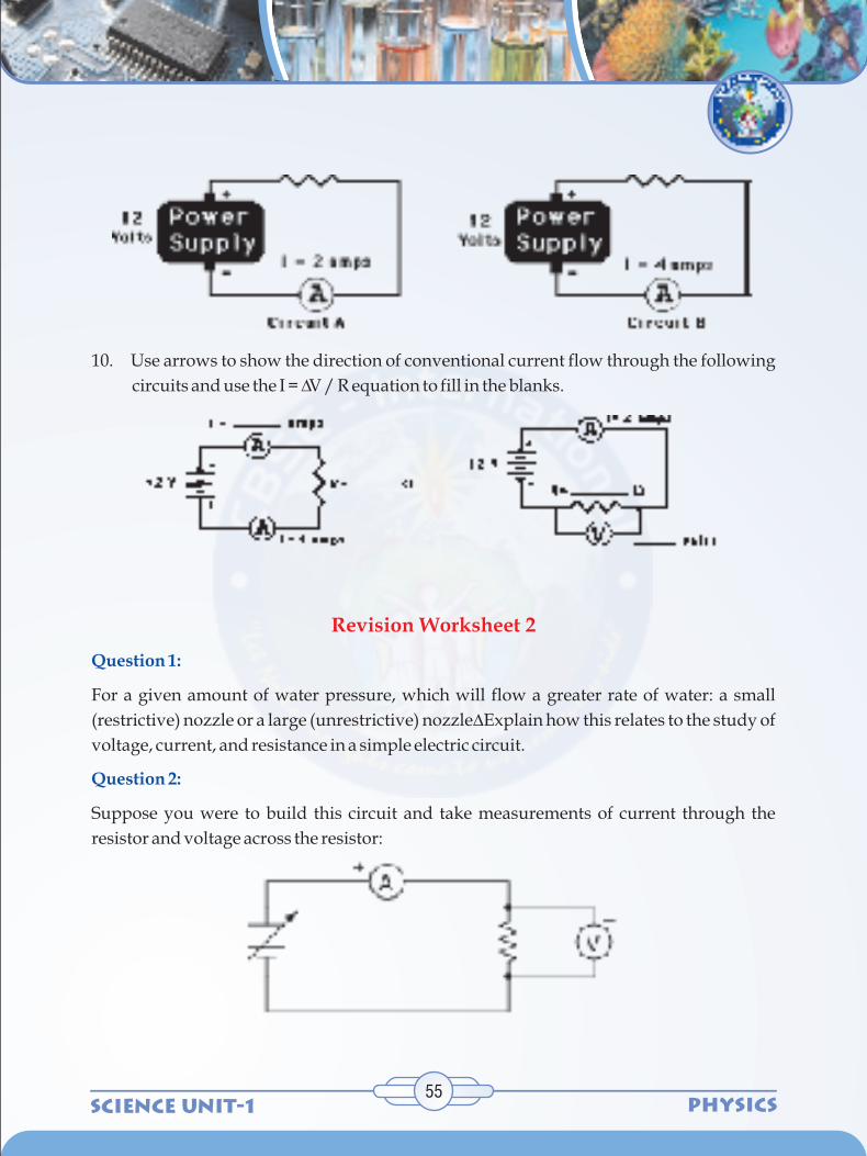
SCIENCE UNIT-1 PHYSICS55
10. Use arrows to show the direction of conventional current flow through the following
circuits and use the I = ?V / R equation to fill in the blanks.
For a given amount of water pressure, which will flow a greater rate of water: a small
(restrictive) nozzle or a large (unrestrictive) nozzle? Explain how this relates to the study of
voltage, current, and resistance in a simple electric circuit.
Suppose you were to build this circuit and take measurements of current through the
resistor and voltage across the resistor:
Revision Worksheet 2
Question 1:
Question 2:

SCIENCE UNIT-1PHYSICS
Recording these numerical values in a table, the results look something like this:
Current Voltage
0.22 A 0.66 V
0.47 A 1.42 V
0.85 A 2.54 V
1.05 A 3.16 V
1.50 A 4.51 V
1.80 A 5.41 V
2.00 A 5.99 V
2.51 A 7.49 V
Plot these figures on the following graph:
56

SCIENCE UNIT-1 PHYSICS57
What mathematical relationship do you see between voltage and current in this simple
circuit?
Explain, step by step, how to calculate the amount of current (I) that will flow through the
resistor in this circuit:
Plot the relationships between voltage and current for resistors of three different values
(1 ? , 2 ? , and 3 ? ), all on the same graph:
What pattern do you see represented by your three plots? What relationship is there
between the amount of resistance and the nature of the voltage/current function as it
appears on the graph?
Question 3:
Question 4:

SCIENCE UNIT-1PHYSICS
Question 5:
Question 6:
Question 10:
Question 11:
What is the value of this resistor, in ohms?
A common saying about electricity is that ït always takes the path of least resistance."
Explain how this proverb relates to the following circuit, where electric current from the
battery encounters two alternate paths, one being less resistive than the other:
What would happen if a wire having no resistance at all (0 ? ) were connected directly
across the terminals of a 6-volt battery? How much current would result, according to
Ohm's Law?
Suppose we were to short-circuit a 6-volt battery in the manner just described and measure
8 amps of current. Why don't the calculated figures from the previous paragraph agree
with the actual measurement?
Shunt resistors can be used as a current-measuring device, By measuring the amount of
voltage dropped across a shunt resistor, one can determine the amount of current going
through it:
58

SCIENCE UNIT-1 PHYSICS59
Suppose that a shunt resistance is labeled with the following rating: 75 A , 25 mV. What is
the resistance of this shunt, in ohms?
One of the fundamental equations used in electricity and electronics is Ohm's Law: the
relationship between voltage (E or V, measured in units of volts), current (I, measured in
units of amperes), and resistance (R, measured in units of ohms):
Where,
V = Voltage in units of volts (V)
I = Current in units of amps (A)
R = Resistance in units of ohms (? )
Solve for the unknown quantity (V, I, or R) given the other two
I = 20 mA, R = 5 k? ; V =
I = 150 ? A, R = 47 k? ; V =
V = 24 V, R = 3.3 M? ; I =
V = 7.2 kV, R = 900 ? ; I =
Question 12:
V = IR I = VR R =
VI

SCIENCE UNIT-1PHYSICS
V = 1.02 mV, I = 40 ? A; R =
V = 3.5 GV, I = 0.76 kA; R =
V = 477 V, R = 0.00500 ? ; I =
V = 0.02 V, R = 992,000 ? ; I =
V = 150,000 V, I = 233 A; R =
A quantity often useful in electric circuit analysis is conductance, defined as the reciprocal
of resistance:
The unit of conductance is the siemens, symbolized by the capital letter "S". Convert the
following resistance values into conductance values, expressing your answers in both
scientific and metric notations:
R = 5 k ? ; G =
R = 47 ? ; G =
R = 500 M ? ; G =
R = 18.2 ? ; G =
Suppose an electric current of 1.5 microamps (1.5 mA) were to go through a resistance of 2.3
mega-ohms (2.3 M? ). How much voltage would be "dropped" across this resistance? Show
your work in calculating the answer.
1. Determine the equivalent resistance for the following sets of resistors.
Question 13:
Question 14:
REVISION WORKSHEET 3
60
G = 1R

SCIENCE UNIT-1 PHYSICS61
2. The circuits below are known as combination or compound circuits; they are
composed of resistors which are arranged both in parallel with each other as well as
other resistors arranged in series with each other. In each circuit, the resistors which
are arranged in parallel have the same resistance value. For each combination circuit
shown below, determine the equivalent resistance for the combination of three
resistors, the total current (i.e., at the battery), and the current at each of the three
indicated locations.
R = ___________ R =_____________eq eq
I = ___________ I = _____________tot tot
R =____________________ R =_______________eq eq
I =____________________ I =__________________tot tot

SCIENCE UNIT-1PHYSICS
3. The electric potential at a given location in a circuit is the amount of _____________
per ___________at that location. The location of highest potential within a circuit is at
the _______ ( +, - ) terminal of the battery. As charge moves through the external
circuit from the ______ ( +, - ) to the ______ ( +,- ) terminal, the charge loses potential
energy. As charge moves through the battery, it gains potential energy. The difference
in electric potential between any two locations within the circuit is known as the
electric potential difference; it is sometimes called the _____________________ and
represented by the symbol ______. The rate at which charge moves past any point
along the circuit is known as the ___________________ and is expressed with the unit
________________.
The diagram at the right depicts an electric circuit in a car. The rear defroster is
connected to the 12-Volt car battery. Several points are labelled along the circuit. Use
this diagram for questions #4-#8.
4. Charge flowing through this circuit possesses 0 J of potential energy at point ___.
5. The overall effect of this circuit is to convert ____ energy into ____ energy.
a. electrical, chemical b. chemical, mechanical
c. thermal, electrical d. chemical, thermal
6. The potential energy of the charge at point A is ___ the potential energy at B.
a. greater than b. less than
c. approximately equal to
7. The + charge gains potential energy as it moves between points ___ and ___.
a. A and B b. B and C
c. C and D d. D and A e. none of these
62

SCIENCE UNIT-1 PHYSICS63
8. The + charge loses potential energy as it moves between points ___ and ___.
a. A and B b. B and C
c. C and D d. D and A e. none of these
9. The rate at which energy is delivered to a circuit by the energy source or the rate at
which energy is consumed by an electrical device is known as the electric ______.
a. current b. potential
c. voltage d. power
10. The unit of electric power is the _____.
a. Ampere b. Volt
c. Watt d. Joule
11. Mechanical power (discussed in a previous unit) is the rate at which work is done on
an object. Electrical power is the rate at which work is done on a charge (by the
battery) or on an electrical device (by the charge). In terms of an equation, it is … . (Fill
in the numerator and the denominator.)
a. A 60-Watt light bulb uses up ____________ J of energy when left on for _____ 1
hour (3600 s).
b. A 60-Watt light bulb uses up ____________ J of energy when left on for _____ 4
hours.
c. A 1500-Watt hair dryer uses up ____________ J of energy when used for _____ 5
min (300 s).
d. A 120-Watt fan uses up ____________ J of energy when left on for _____ a day.
12. Substitution of other electrical equations ( I = Q/t and V = I•R and V = W/Q ) into the
power equation yields the following three equations.
P = IV
2P = I R
2P = V / R
Use these equations to solve the following problems.
a. Calculate the resistance of a toaster oven if its power is 800 W when connected to
a 110-V outlet.

SCIENCE UNIT-1PHYSICS
b. Calculate the resistance of the 1000 W microwave oven which gets plugged into
to a 110-V outlet.
c. The TI-84 calculator uses four 1.5-V batteries and has a power of 0.0008 W. What
is the current?
1. Determine the consumption of electrical energy of your household for a day.
Calculate the number of units and the cost for the same for a month of 30 days.
2. Give examples where series and parallel connections are used and the reason for a
particular connection to be used for specific purposes.
Project:
64

SCIENCE UNIT-1 PHYSICS
Rubrics of Assessment For Learning
Beginning
(1)
Parameter
Learner is able to
•
•
•
•
•
Explain an electric
circuit and Draw a
circuit using simple
symbols for the
components of an
electric circuit.
Define electric
potential, potential
difference and
current and
Understand the
relation between
them.
Define and Explain
resistance and derive
an expression for
resistance.
Explain and Verify
Ohm's law
Understand and
Describe the two
different types of
combination of
resistors - series and
parallel circuits.
65
Approaching
(2)
Meeting
(3)
Exceeding
(4)

SCIENCE UNIT-1PHYSICS66
Beginning
(1)
Parameter
Learner is able to
•
•
•
Explain the heating
effect of current.
Understand and
Explain the practical
application of heating
effect of current.
Solve numerical
problems on
resistance,
combination of
resistors, ohm's law
and heating effect of
current and power
consumption
Approaching
(2)
Meeting
(3)
Exceeding
(4)