Embed Size (px)
Citation preview


Motorcycle Handling and Chassis Design
the art and science
Tony Foale

Copyright © 2002 Tony Foale
All rights reserved. Printed in Spain.
First printing.
ISBN for CDROM ISBN for book Ordering information is available on the internet at www.tonyfoale.com and by email at [email protected].
Comments or notifications of any errors are welcome and should be sent to [email protected].
WARNING – Important safety and legal notice.
Building and/or modifying motorcycle chassis or parts is a serious undertaking and the consequences of mechanical failure can result in serious injury. Some of the practices and designs outlined in this book may be dangerous unless implemented by skilled and experienced people who have qualifications in engineering, design and fabrication. The author has tried to ensure the accuracy of the contents of this book, but some text, of necessity, represents the opinion and experience of the author and is not guaranteed to be fact. Therefore, the book should be read whilst mindful of the potential risks of motorcycle modification, both in racing and other use. It is for this reason that the author makes no warranties, explicit nor implied, that the information contained herein is free of error nor that it will meet the purpose of any specific application. The author disclaims any liability for any and all forms of damage that result from any use of the contents in this publication.

Foreword The motorcycle is a complex system that has long defied full analysis. For a very long time, motorcycle handing was hardly even considered a subject. Engines, whose performance could be measured in "objective" terms, therefore received the lion's share of development. Engine development moved rapidly ahead of chassis, suspension, and tires, creating a succession of design crises that required new thought for their solution. Examples might be Rex McCandless's twin-loop swingarm chassis of 1950, Tony Mills's wide, belted Dunlop Daytona tire of 1974, and the present-day elaborations of Antonio Cobas's large-section aluminium twin-beam chassis of the early 1980s. In each case, motorcycle performance had ceased to advance because of specific problems that could not be solved by traditional means.
In general, the innovations that have broken these deadlocks have been creations of practical persons, not of theorists. The role of theory in motorcycle design has, if anything, suffered at the hands of history, for the strange forkless creations of ELF, Fior, and Bimota have come and gone without solving any actual problem.
Yet motorcycle performance is at present again deadlocked, with no sunny uplands of easy progress in sight. As motorcycles lean over farther on their wonderful tires, their suspensions turn sideways, at a large angle to the bumps they are designed to absorb. As engine and brake torque is applied, motorcycles short enough to turn quickly, and tall enough for adequate cornering clearance suddenly lift the front or rear wheel, limiting maximum rates of acceleration and deceleration. While autos present 100% of the width of their tires to the pavement, the motorcycle offers only 1/3 of tread width at a time, severely limiting cornering grip. To make motorcycles steer well, front tires must be of modest section, while rears, to apply engine power, must be large. With the forward CG position necessary for rapid acceleration, a powerful motorcycle must therefore overload its small front tire in cornering, while under-using its larger rear. The result is that as a machine's power increases, its corner speed must decrease.
Racing is the environment in which these problems hurt worst, and from which solutions have most often come. Racing has, however, evolved from a sport into a conservative business. The practical men of racing are now too busy loading and unloading their beautifully painted transport trucks to have much time for innovation. The theoreticians remain, as ever, divorced from practicality, often ignorant of the real problems motorcycles confront.
Yet the infinite refinement of the piston internal combustion engine did not create the gas turbine - only a careful consideration of theoretical heat engine cycles could make that leap. Therefore the practical and theoretical sides need each other - but they have had little dialogue thus far.
This book is a valuable step toward that dialog. Tony Foale's first book was almost entirely practical, and has been deservedly widely read. He is a man who can control a weld puddle and twist safety wire. He also knows that refinement within existing thought must ultimately reach a dead end. This has forced him to learn to walk with one foot upon practicalities and the other upon theory. This new book is the result. Read on.
Kevin Cameron. Technical editor Cycle World magazine. March 2002.
Acknowledgements It is quite usual that the author of a book has various people to thank for providing help in its preparation. In my case I have hundreds to thank. Prior to publication in book form, preview versions of the manuscript were made available on CDROM, in different stages of completion. In total about 250 CDs were distributed, and the feedback and notification of errors from a sizable proportion of those readers has proved to be an invaluable aid.
The numbers make it impossible to name everyone, but you know who you are – thanks a lot, you made the job much easier.
Another source of aid came from those who have supplied information, expert proof reading or contributed ideas for topics without which this book would have been the poorer. This group is small enough to thank individually and it gives me pleasure to be able to so. They are, in alphabetical order:
Dr. Andreas Fuchs – Innovative Mobility. ( www.swissmove.ch )
Arnold Wagner – Ecomobile. ( www.peraves.ch )
Carlos Calleja. – ( www.moebius.es/~ccalleja/ )
David Sanchez. – ( www.bottpower.com )
David Searle – Motorcycle Consumer News. ( www.mcnews.com )
Douglas Milliken – Milliken Research Associates, Inc. ( www.millikenresearch.com )
Hubert Kleis and Rainer Diabold – 2D Meßsysteme GmbH. ( www.2D-Datarecording.com )
Ian Drysdale – Drysdale Motorcycle Company. ( http://home.mira.net/~iwd )
Keith Duckworth.
Peter Hopkins – BMW UK. ( www.bmw-motorrad.co.uk/ )
Peter McNally – Avon tyres. ( www.coopertire.com/avon_motorcycle/frames.htm )
Dr. Robert Lewis – Advantage CFD. (www.advantage-cfd.co.uk & www.reynard-motorsports.com)
Roberto Lot – University of Padova. ( www.mecc.unipd.it/~cos/DINAMOTO/indexmoto.html )
Dr. Robin Sharp – Cranfield University. ( www.Cranfield.ac.uk )
Dr. Robin Tuluie – MTS Systems Corp. ( www.mts.com )
Ted Blais – Rokon. ( www.rokon.com )

Preface The book “Mototorcycle Chassis Design” was first published in 1984 and was subsequently reprinted several times without under-going change. Although out of print for over 12 years or so, I know from personal inquiries that there is still considerable demand for a book on this subject. A new book was obviously well overdue, although much of the original material is as current today as it always has been. After all, the laws of Newtonian Physics tend to be stable over time.
During the nearly two decades since the original book, the motorcycle chassis has undergone gradual evolutionary change and there is no doubt that handling in general has improved. In the 1970s. the main emphasis was on ever more powerful engines being fitted into flexible tubular frames unable to provide a reasonable level of handling or stability. Thankfully that has generally changed. Forks, frames and swing-arms have become much more rigid, and in some cases lighter as well, at least at the sport bike end of the market. The change to radial ply tyres has been of the utmost importance to this process of change. Despite the prophecies of many commentators the front suspension of choice is still the telescopic fork, although generally much improved. For any number of reasons manufacturers have been reluctant to experiment with other forms in the marketplace. This probably has more to do with the product liability lawyers than it has to do with the engineers. There have been two notable exceptions amongst the major manufacturers. Although now out of production, Yamaha marketed the GTS with a suspension design based on the work of James Parker. BMW changed over completely to the “Telelever” system, similar in principle to the design used by the British Saxon concern.
I’ve had considerable feedback from readers of that first book and I’ve done my best to incorporate the many suggestions. Although greatly enlarged, most of the original subject matter remains. Many topics have under gone revision to improve clarity or remove ambiguity. Material has be added which explores in more depth those subjects which were only briefly mentioned in the original book, mostly due to publishing space constraints. An example of this is the description of initiating a turn, this topic is central to an understanding of motorcycle behaviour. However, it was then covered only briefly, the content on this subject is considerably enhanced in the current book. Completely new chapters have been added on various topics that just weren’t in the original. For example: tyres, aerodynamics, the important subject of anti-squat and a case study of improving a standard production frame for racing.
Since the first book was published the sport of motorcycling in all forms has become much more technical and so in order to do the subject justice this book has had to become more technical also. Reviewers of the previous book praised the lack of drawn out explanations, I have tried to maintain this characteristic where possible, but within the need for coverage in greater depth. This book is not intended as a handbook for chassis setup etc. rather it is an attempt to provide the reader with the background knowledge of how and why motorcycles react in the way that they do. An understanding at this level will however, equip the reader to undertake his own design, modifications or setup with greater confidence. The acquisition of knowledge is rarely easy and requires commitment, any book is purely a passive aid and the benefit to each reader will depend on the effort put into it. It is probably best to initially read it through quickly , ignoring some of the detail to get an overall view and then to re-read it to gain a more in-depth appreciation of the subject. It is also recommended that the reader looks at some of the appendices for background information, prior to tackling the main text. In particular appendices 2,3 and 4.
There are a wide range of technical topics discussed within a relatively small book and so in some cases a prior knowledge of the basics has had to be taken for granted. Naturally some parts of the general text are more technical than others, but there should be little problem for any interested enthusiast in gaining a better understanding of the principles involved. It is not necessary to understand every last detail to derive benefit.
To cover the subject adequately it is impossible to completely avoid mathematics, I have tried to keep this as simple as possible. The level of mathematics used is deliberately kept at a level below that requiring a knowledge of calculus, in the hope that the book will be of use to the widest range of readers. A multitude of diagrams and graphs from both data logging and computer simulation have been used to demonstrate various phenomenon without a great number of formulae.
Even in this age of much greater technical understanding, there are still many aspects of design and handling setup that can better be described as art more than science. Hence, the book title has been changed to reflect this. All engineering design is the art of compromise, the best bike is the one whose designer has achieved the best overall compromise for the intended purpose, whether that be racing or commuting. We often hear that competition machines are built with no compromises, in fact the opposite is true. Highly focused machines such as racers are probably subject to the biggest compromises of all. Throughout the book I have tried to emphasize the conflicting requirements that always compromise any design or setup decision. Nowhere is this more evident than when selecting suspension characteristics, this is demonstrated at every race meeting where much time is spent making minute adjustments to achieve the “optimum” setup.
Many points in the text are illustrated with example photographs. It has been a policy to use older examples where possible to acquaint younger readers with some of these machines and also to demonstrate that much of what is regarded as being new has in fact been around for a considerable period. Most readers will in any case be familiar with photos of modern examples from the general motorcycle press.
The first book was co-authored by Vic Willoughby, undeniably the doyen of motorcycle technical journalists. When I was a teenager (many years ago) I would read his weekly articles many times over and there’s no doubt that these played a great part in the motivation for me to start designing and making my own chassis. Many years later I was privileged enough for him to write articles describing some of my work. We became friends and I was honoured when he agreed to help when I approached him with the idea for the original book. He was in his retirement then but still had enormous energy for the task. Unfortunately, Vic passed away in November 2000 and I have undertaken this new book solo, and so must take sole responsibility for any errors.
I would however, like to dedicate this book to Vic. without whom the original would never have passed the idea stage. Tony Foale, Spain
March 2002

Dedicated to the memory of Vic Willoughby.

1
Contents
1 Function and history
Some basic definitions ................................................... 1-1 Function .......................................................................... 1-3 History............................................................................. 1-4 Front suspension.......................................................... 1-16 Rear suspension........................................................... 1-23 Spring types.................................................................. 1-29 Load Compensation ..................................................... 1-30
2 Tyres
Weight support ............................................................... 2-2 Suspension action .......................................................... 2-4 Tyre stiffness or spring rate............................................ 2-8 Contact area ................................................................. 2-11 Area when cornering .................................................... 2-15 Friction (grip) ................................................................ 2-15 Braking & driving .......................................................... 2-17 Cornering ...................................................................... 2-17 Mechanisms of grip ...................................................... 2-17 Under- and over-steer .................................................. 2-27 Construction ................................................................. 2-32 Materials ....................................................................... 2-34 Summary ...................................................................... 2-34

2 Contents
3 Geometric considerations Basic motorcycle geometry ............................................ 3-1 Trail ................................................................................. 3-1 Rake or castor angle (steering axis inclination) ............. 3-5 Wheelbase.................................................................... 3-15 Wheel diameter ............................................................ 3-16 Other considerations .................................................... 3-18 Angular motions............................................................ 3-22
4 Balance and steering
Balance........................................................................... 4-1 Steering .......................................................................... 4-3 Gyroscopic effects only .................................................. 4-9 Gyroscopic with tyre camber force only. ...................... 4-12 Gyroscopic with tyre camber and steer forces............. 4-14 Tyre forces only – no gyroscopic effects. .................... 4-18 Body lean only – no steering........................................ 4-20 Conclusions: ................................................................. 4-23
5 Aerodynamics
Drag ................................................................................ 5-1 Evolution of the racing fairing......................................... 5-9 Internal air flow ............................................................. 5-10 Lift ................................................................................. 5-11 Airflow evaluation ......................................................... 5-18 Side wind stability (traditional view) ............................ 5-21 Steady state directional stability................................... 5-24 Dynamic directional stability ......................................... 5-28 Summary ...................................................................... 5-31
Contents 3
6 Suspension principles
Springs............................................................................ 6-1 Damping ......................................................................... 6-8 Sprung and unsprung mass ......................................... 6-21 Basic suspension principles ......................................... 6-21 Other factors................................................................. 6-31 Lateral suspension ....................................................... 6-42 Summary ...................................................................... 6-49
7 Front suspension
Head stock mounted forks ............................................. 7-1 Alternatives to the head stock mounted fork................ 7-13 Hub centre steered ....................................................... 7-14 Double link.................................................................... 7-18 McPhearson strut based .............................................. 7-27 Virtual steering axis ...................................................... 7-31
8 Rear suspension
Effective spring rate........................................................ 8-3 Chain effects................................................................. 8-11 Wheel trajectory............................................................ 8-15 Structural ...................................................................... 8-16 Single or dual sided ...................................................... 8-19 Summary ...................................................................... 8-26

4 Contents
9 Squat and dive
Load transfer .................................................................. 9-1 Squat and dive................................................................ 9-4 Shaft drive....................................................................... 9-4 Chain drive.................................................................... 9-13 Aerodynamic squat....................................................... 9-25 Braking reaction (rear).................................................. 9-26 Dive (front) .................................................................... 9-29 Dynamic effects............................................................ 9-37 Summary ...................................................................... 9-47
10 Structural considerations
Fatigue .......................................................................... 10-1 Structural efficiency ...................................................... 10-1 Triangulation................................................................. 10-2 Beam frames ................................................................ 10-5 Triangulated frames ..................................................... 10-9 Tubular backbone....................................................... 10-11 Structural comparison ………………………………….10-12 Fabricated backbone .................................................. 10-14 Monocoque ................................................................. 10-15 Structural engine ........................................................ 10-17 Conventional multi-tubular ......................................... 10-20 Twin-spar .................................................................... 10-23 Other types ................................................................. 10-27 Summary .................................................................... 10-28
11 Engine Mounting
Contents 5
12 Braking
The basics .................................................................... 12-1 Effects of CoG height ................................................... 12-7 Generation of torque .................................................... 12-9 Hardware .................................................................... 12-10 Discs ........................................................................... 12-11 Calipers....................................................................... 12-14 Pads............................................................................ 12-15 Linked brakes ............................................................. 12-15 ABS............................................................................. 12-17
13 Materials and properties
Typical properties of some common materials ............ 13-3 Frame ........................................................................... 13-5 Wheels .......................................................................... 13-8 Fuel tank ..................................................................... 13-13 Brake discs ................................................................. 13-13 Bodywork.................................................................... 13-13
14 Stability & control Under-/over-steer ......................................................... 14-2 High-siding.................................................................... 14-7 Stability under braking.................................................. 14-9 Instabilities .................................................................. 14-10 Damping ..................................................................... 14-14
15 Performance measurement Track side ..................................................................... 15-1 Laboratory..................................................................... 15-9 Strength analysis .......................................................... 15-9 Measurement and simulation ..................................... 15-12 Future development ................................................... 15-14

6 Contents
16 Practical frame building
Welding ......................................................................... 16-1 Distortion....................................................................... 16-3 Gussets......................................................................... 16-5 Jigging .......................................................................... 16-6 Tube profiling ................................................................ 16-8 Tube types .................................................................... 16-9 Tube sizes .................................................................. 16-10 Frame finishes ............................................................ 16-11 Design layout .............................................................. 16-12
17 Case study
Measurement................................................................ 17-2 Main frame.................................................................... 17-2 Engine mounting........................................................... 17-5 Results .......................................................................... 17-5 Material ......................................................................... 17-5 Swing arm..................................................................... 17-5 Forks ............................................................................. 17-6 Caution ......................................................................... 17-6 Tuning ........................................................................... 17-6
18 Future developments The status quo .............................................................. 18-1 Future possibilities........................................................ 18-2 Active suspension......................................................... 18-2 Rheological Fluids ........................................................ 18-4 Two wheel drive (2WD) ................................................ 18-4 Two wheel steering (2WS) ........................................... 18-8 Feet-Forward motorcycles. (FF)................................ 18-12

Contents 7
Appendices A1 Experiments with rake and trail
Rake..............................................................................A1-1 Trail ...............................................................................A1-7 Conclusions ..................................................................A1-8 Post script.....................................................................A1-8
A2 Glossary of terms
A3 Units conversion
A4 Gyroscopic effects
A5 Basic physics of motorcycles
Basic Trigonometry ......................................................A5-1 Units of angle................................................................A5-2 Velocity .........................................................................A5-3 Acceleration..................................................................A5-4 Mass .............................................................................A5-4 Momentum....................................................................A5-5 Newton’s laws...............................................................A5-6 Force and weight ..........................................................A5-7 Moments, couples and torque......................................A5-8 Centripetal & centrifugal force......................................A5-9 Addition and resolution of velocities and forces ........A5-10 Work, energy and power ............................................A5-12 Nomenclature and sign conventions..........................A5-13 Normalization..............................................................A5-14
A6 Analysis of mechanisms
A7 CoG and mass distribution of rider
A8 Typical data

1-1
1 Function and history Some basic definitions Before getting into much detail we need to consider some definitions of terms that are often banded about loosely and misunderstood as a consequence.
Handling By this, we mean the ease, style and feel with which the motorcycle does our bidding. It depends mainly on overall geometry, chassis stiffness, weight and its distribution, tyre type and size. It may come as a surprise to some people to learn that the rider has a major influence on the handling characteristics of a motorcycle. Rider responses have a large effect on the overall interaction of the dynamic forces that control the motion of the machine.
Roadholding This means the ability of the machine, through its tyres, to maintain contact with the road. It depends mainly on tyre type and size, suspension characteristics, weight and its distribution, and stiffness between the wheels to maintain their correct relationship to one another. In the days of relatively narrow tyres, roadholding and handling generally went hand-in-hand, indeed, the terms were used interchangeably. However, nowadays the requirements are sometimes contradictory and a compromise must be struck, depending on the intended use of the machine.
A big enemy of tyre grip and hence roadholding is dynamic variation in the vertical load at the road interface, there are many factors that contribute to such variation and we shall see that suspension parameters are important as a means of providing control over this aspect.
Stability There are many types of stability or instability that can influence a motorcycle. There’s balance stability, aerodynamic stability etc. Formal definitions of stability in control systems exist but they are too involved for a book of this nature, although we’ll look at these aspects a bit closer in a later chapter. For our present purposes we mean:
The ability to maintain the intended manoeuvre (i.e. continue in a straight line or round a corner) without an inherent tendency to deviate from our chosen path. This implicitly includes the absence of wobbles and weaves.
The ability to revert to the intended manoeuvre when temporarily disturbed by external forces (e.g. bumps, cross winds and so on).
Handling, roadholding and stability are affected by many parameters and the interaction between them. The subject is complex but not magic, and – judging from some chassis designs – has not always been well understood. However, relatively simple laws of physics are always obeyed. This book will try to remove the mysteries and consider the main parameters involved and study their various effects. It must be emphasized that there is much cross-coupling between these effects – there is no ’correct’ combination, no ’perfect’ design. Any motorcycle embodies several essential compromises.

Function and History
1-2
Linear and angular motions If we are to study the behaviour of any type of vehicle we first need to consider just how it can move. The linear motions are easy to visualize, firstly the machine can move in a forward direction and the engine and brakes are responsible for controlling this. Road undulations and hills cause motion in a vertical direction and sidewinds can result in sideways movement. It is the angular motions that are somewhat less familiar to most people. The overall angular movements can be completely described by considering the motions about three separate axis. These axis are at right angles to one another and are known as roll, pitch and yaw.
Fig. 1.1 Showing the three principal axis of rotation.
Yaw is the angular motion about a vertical axis.
The pitch axis is horizontal and passes sideways through the bike.
The roll axis is also horizontal and is orientated fore and aft.
Roll is probably the most familiar of the three and is the most obvious motion that occurs when we lean the bike over for cornering. Fig. 1.1 shows the roll axis passing through the CoG. However, as we shall see later the location of this axis depends on our frame of reference.
Yaw is the movement about a vertical axis and occurs as we steer around a bend, it can also be caused by various disturbances such as sidewinds.
Pitch is the motion about an horizontal axis that passes sideways through the machine, we get this under braking and acceleration, as well as from road irregularities.
Due to the large roll angles involved with cornering, the pitch and yaw axis of the machine move relative to the global vertical and horizontal coordinates. For this reason it is important to be careful when specifying the axis system that we are using. There are several such systems that are used in vehicle analysis but for our purposes the two most important will be the machine coordinates and earth coordinates, initially defined in terms of the original direction of travel, before performing some manoeuvre.

Function and History 1-3
Function The functions of a motorcycle frame are of two basic types: static and dynamic. In the static sense the frame has to support the weight of the rider or riders, the engine and transmission, and the necessary accessories such as fuel and oil tanks. Although less obvious, the frame’s dynamic function is critically important. In conjunction with the rest of the rolling chassis (i.e. suspension and wheels) it must provide precise steering, good roadholding, handling and comfort.
For precise steering the frame must resist twisting and bending sufficiently to keep the wheels in their proper relationship to one another regardless of the considerable loads imposed by power transmission, bumps, cornering and braking. By proper relationship we mean that the steering axis must remain in the same plane as the rear wheel, so as to maintain the designed steering geometry in all conditions without interference from frame distortion.
Clearly, however, no steering system can be effective while the wheels are airborne, hence the importance of good suspension, especially at the front. Good handling implies that little physical effort should be required for the machine to do our bidding, so avoiding rider fatigue. (This requirement is largely a function of centre-of-gravity height, overall weight, stiffness, steering geometry, tyre sizes and the moments of inertia of the wheels and overall machine/rider combination.)
Comfort is important to minimize rider fatigue also, and requires the suspension to absorb bumps without jarring the rider or setting up a pitching motion. All these criteria the frame has to fulfil for the expected life of the machine, without deterioration or failure and without the need for undue maintenance.
It should be borne in mind, however, that all design is a compromise. In any particular example, the precise nature of the compromise will be governed by the use for which the machine is intended, the materials available and the price the customer is prepared to pay.
History Tubular frames Over the years designers have been repeatedly criticized for their seeming reluctance to depart from the diamond-pattern frame inherited from the pedal cycle. However, since the earliest motorcycles were virtually pushbikes with small low-powered engines attached at various places, that was the logical frame type to adopt, particularly so long as pedal assistance was required.
Until the general adoption of rear springing several decades later, this diamond ancestry (including its brazed-lug construction) was discernible in most frame designs. This was hardly surprising as the frame’s depth suited the tall single-cylinder engines that were popular for so long. In any case the motorcycle, like the pedal cycle, was after all a single-track vehicle in which the use of an inclined steering head was a convenient way to provide the front-wheel trail necessary for automatic straight-line stability.
Once pedals were discarded, the frame with the closest resemblance to the ancestral pedal type was the simple diamond pattern in which the engine’s crankcase replaced the cycle’s bottom bracket to span the lower ends of the front tube and seat tube. For many years both before and after the first world war this type of frame was the overwhelming choice of the established manufacturers. An earlier variant of the diamond pattern was the single-loop frame in which the front tube and seat tube were bent from a single length, which passed underneath the engine. An improvement on both was the cradle frame. In this, the

Function and History
1-4
bottom ends of the single front and seat tubes were spaced farther apart and rigidly connected by a brazed-in engine cradle, from the rear of which the tubes reached upward to the wheel-spindle lugs.
Cradle frame, successor to the diamond bicycle pattern . The cradle tubes are extended rearward to the wheel spindle lugs.
In the duplex cradle frame the cradle tubes are also extended upward to the steering head.
A straightforward development of this layout was the duplex cradle frame, in which the cradle tubes were continued upward to the steering-head lug as well as to the rear spindle lugs. Both types of cradle frame suited the upright single-cylinder engine by providing room for the narrow crankcase to be slung very low, engines with wider crankcases had to be mounted higher, so raising the centre of gravity.
In the design of these early frames, torsional and lateral stiffness seem to have been given a low priority. However, there were some commendable efforts between the wars to ensure the all-important torsional and lateral stiffness through triangulation of the frame structure. In the Cotton, the four long tubes connecting the steering head directly to the rear spindle Iugs were triangulated in both plan view and elevation, and the machine was renowned for its excellent steering.
Triangulated in both plan and elevation, the straight-tube Cotton frame was renowned for its steering.
A few attempts were made to stiffen the support of the steering head by incorporating it in one end of a cast H-section frame member, this type of structure replaced the front down tube in the Greeves and the top tube in some BSAs.

Function and History 1-5
A 1960s. picture of the author racing a Greeves Silverstone with cast aluminium H-section front down member, incorporating the steering head. The under-frame was an open channel section fabricated from steel sheet, a bent steel tube backbone completed the frame loop.
Bolted-up from straight tubes (for easy repair) and relying on the power plant for some of its stiffness, the Francis-Barnett was fully triangulated from the steering head to the saddle, though the rear end was triangulated only in the vertical plane. Another frame to depend on the engine for part of its stiffness was the open Scott. In this the rear end was triangulated fully but the steering head only laterally – which was much the more important plane from the steering viewpoint. The front brake of the day was hardly powerful enough to tilt the head significantly in the fore-and-aft plane; and even if it did, that would not have impaired the steering nearly so much as would twisting the head sideways. The Scott too earned an enviable reputation for its steering.

Function and History
1-6
Fully triangulated at the front but only vertically at the rear, this Francis-Barnett frame could be easily repaired by renewing any of the bolted-in tubes.
Triangulated fully at the rear but only laterally at the front, this early Scott frame relied on the engine for some of its stiffness.
When “plunger” sprung rear ends began to take over from the unsprung variety, many manufacturers simply opened up the rear part of their cradle frames to accommodate the spring units. In most cases only a thin wheel spindle held the two spring units together and so with many designs there was a lot of differential movement between the two sides, resulting in the rear wheel twisting out of line with the rest of the machine. Often, despite the welcome increase in comfort and sometimes in roadholding, there was a deterioration in handling and stability compared to their unsprung forebears. In fact the Norton plunger sprung frame earned the nickname of “garden gate”. Its general handling was thought to be akin to riding that particular piece of garden furniture.
A revolution was started in 1950 when the works Norton racers were supported by the McCandless Bros. designed “featherbed” frame. It is hard to over-estimate the influence that this design has had on subsequent chassis development.
This shows just how easy it was to fit plunger springing in place of the then standard unsprung rigid rear end. This design reduced the amount of re-tooling required.
The legendary Norton “featherbed” frame. The crossing over of the tubes at the steering head facilitated the use of a flat-bottom tank but impaired stiffness. A head steady was used which connected the steering head and top of the engine to overcome this.

Function and History 1-7
Even now, over half a century later, many current designs still show a direct lineage back to it. The enormous improvement over its predecessor, hinted at by its nickname, probably owed less to any one design feature than to a combination of several. Its duplex-loop layout had mediocre structural efficiency but provided adequate (though not exceptional) stiffness and the general layout was such as to give a fairly even weight distribution and a relatively low centre of gravity (considering the upright position of the cylinder). The front fork was one of the more robust telescopics of the period, and the steering geometry provided light, responsive handling. As with many landmark developments the featherbed’s success probably owes much to being the right product at the right time rather than having any overwhelming technical superiority.
Generally speaking steel has been the most used material for tubular frames although both titanium and aluminium have been used. BSA tried titanium in the 1960s. for their works moto-X bikes, and the 1980s. saw various makers using aluminium alloys for both road and racing frames.
Beams An entirely different approach to the problem of achieving adequate resistance to twisting and bending is to use a large-diameter tube as the main frame member, thus combining a high degree of stiffness with simplicity and light weight. Provided it is of sufficient section, the tube does not necessarily have to be circular, though this is the best shape for torsional stiffness. Indeed, when the NSU Quickly popularised this type of frame at the start of the moped boom in the early 1950s the tube – or beam, to use another name – was made from left and right half-pressings seam-welded together, giving an approximately oval section.
Clearly, however, a plain beam could not connect the steering head directly to the rear-wheel spindle as did the top four tubes in the Cotton frame. Hence it was bifurcated at the rear to accommodate the wheel, and the resulting open channel section of the two arms was closed by welding-in a U-shape strip to restore strength. Welding the beam from two halves in this way made it possible to incorporate any necessary curvature in a vertical plane. NSU used curved beam frames not only on their moped but also on their Max roadster, their 250 cc world championship-winning Sportmax catalogue racing single, the works racing 250 cc Rennmax twin and 125 cc Rennfox single.
In this unsprung beam frame for a moped the open channel section of the rear fork arms is strengthened by a welded-in U-shape strip.
Welded from left and right hand pressings, this NSU beam frame was shaped to accommodate pivoted fork rear springing and to support the engine at the top and rear.

Function and History
1-8
Pivoted-fork or swinging-arm rear springing removed the need to bifurcate the rear end of a frame beam because with this type of suspension it is the swing-arm pivot, not the wheel spindle, to which the steering head has to be stiffly connected. (Naturally, the swing-arm itself should continue the torsional and lateral stiffness back to the spindle.) In the NSU Max and racers, the pressed-steel beam was curved downward at the rear to make a direct connection from steering head to rear pivot.
Winner of the world 250 cc championship in 1953, this NSU Rennmax twin had a curved beam frame welded from left and right halves (MCW)
Because of its extremely large cross-sectional area (sufficient to accommodate a separate 2½ gallon fuel tank inside), the Ariel Leader (and Arrow) frame was probably the stiffest and most outstanding of the beam type. Predictably when pressed into racing service, its steering proved well up to the extra demands.

Function and History 1-9
The Ariel Leader (and Arrow) frame derived great stiffness from the large cross-sectional area of the beam, which enclosed the 11 litre fuel tank.
To make a direct connection between steering head and rear fork pivot, the tubular beam on this early 125 cc Honda GP racer was curved through some 90 degrees. (Salmond)
Other frames – such as that on the early grand-prix Hondas and some Reynolds one-offs – used a large-diameter circular tube, similarly curved, to achieve the same effect. The Honda frame, however, like its duplex successor on the grand-prix fours of the early 1960s, was structurally incomplete without the engine, which was attached at the cylinder head and gearbox.
Function and History
1-10
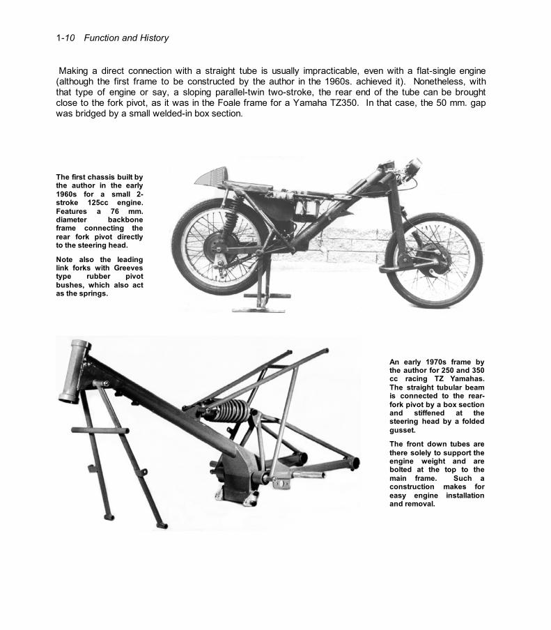
Making a direct connection with a straight tube is usually impracticable, even with a flat-single engine (although the first frame to be constructed by the author in the 1960s. achieved it). Nonetheless, with that type of engine or say, a sloping parallel-twin two-stroke, the rear end of the tube can be brought close to the fork pivot, as it was in the Foale frame for a Yamaha TZ350. In that case, the 50 mm. gap was bridged by a small welded-in box section.
The first chassis built by the author in the early 1960s for a small 2-stroke 125cc engine. Features a 76 mm. diameter backbone frame connecting the rear fork pivot directly to the steering head.
Note also the leading link forks with Greeves type rubber pivot bushes, which also act as the springs.
An early 1970s frame by the author for 250 and 350 cc racing TZ Yamahas. The straight tubular beam is connected to the rear-fork pivot by a box section and stiffened at the steering head by a folded gusset.
The front down tubes are there solely to support the engine weight and are bolted at the top to the main frame. Such a construction makes for easy engine installation and removal.
Function and History 1-11
On a Reynolds frame for a 250cc Moto Guzzi flat single however, the gap was appreciably greater and was spanned by a channel-section light-alloy fabrication, bolted through two cross-tubes welded into the main tube (which doubled as an oil tank) and the box-section sump welded to its underside.
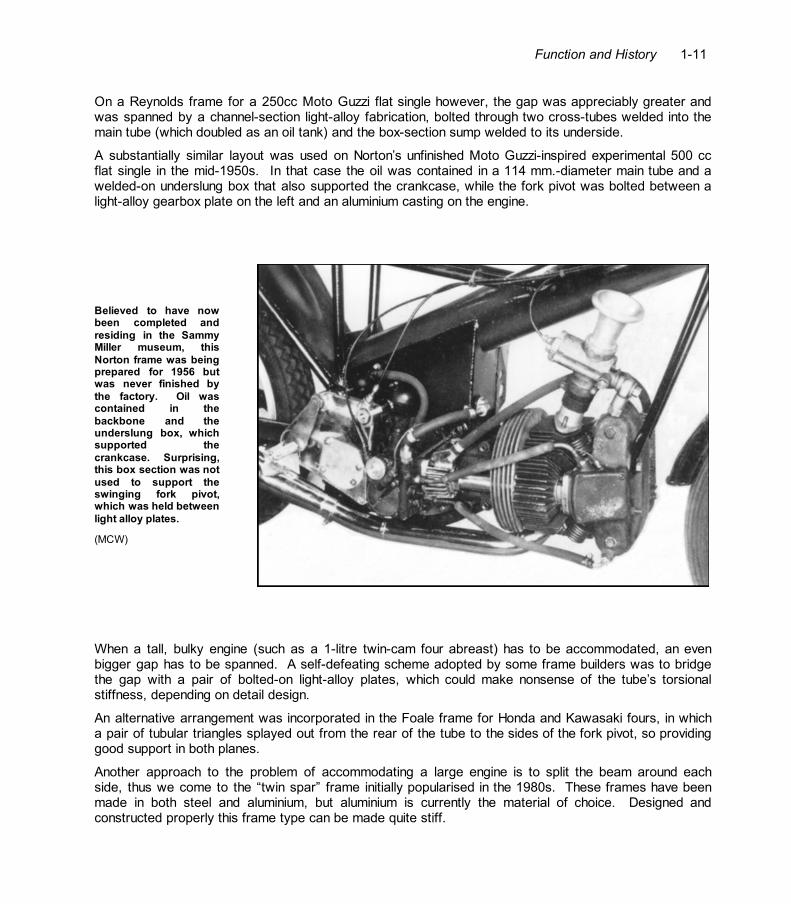
A substantially similar layout was used on Norton’s unfinished Moto Guzzi-inspired experimental 500 cc flat single in the mid-1950s. In that case the oil was contained in a 114 mm.-diameter main tube and a welded-on underslung box that also supported the crankcase, while the fork pivot was bolted between a light-alloy gearbox plate on the left and an aluminium casting on the engine.
Believed to have now been completed and residing in the Sammy Miller museum, this Norton frame was being prepared for 1956 but was never finished by the factory. Oil was contained in the backbone and the underslung box, which supported the crankcase. Surprising, this box section was not used to support the swinging fork pivot, which was held between light alloy plates.
(MCW)
When a tall, bulky engine (such as a 1-litre twin-cam four abreast) has to be accommodated, an even bigger gap has to be spanned. A self-defeating scheme adopted by some frame builders was to bridge the gap with a pair of bolted-on light-alloy plates, which could make nonsense of the tube’s torsional stiffness, depending on detail design.
An alternative arrangement was incorporated in the Foale frame for Honda and Kawasaki fours, in which a pair of tubular triangles splayed out from the rear of the tube to the sides of the fork pivot, so providing good support in both planes.
Another approach to the problem of accommodating a large engine is to split the beam around each side, thus we come to the “twin spar” frame initially popularised in the 1980s. These frames have been made in both steel and aluminium, but aluminium is currently the material of choice. Designed and constructed properly this frame type can be made quite stiff.

Function and History
1-12
Note how the head stock is supported by the two side beams of this 1997 NSR 250 racing Honda. Frame material is aluminium alloy.
Ner-a-Car Although its chassis comprised two full-length, channel-section sides in pressed steel, cross-braced front and rear, the Ner-a-Car of the 1920s defies classification with the beam-type frames if only because it lacked a conventional steering head to connect to the rear-wheel spindle. Indeed, the steering kingpin was set in the middle of the front axle and housed within the front hub – hence the term: hub-centre steering. The axle itself was horizontal, shaped like a U (closed end forward) and pivoted in lugs protruding downward from the chassis sides, with stiff coil springs providing a short suspension travel, which thus varied the kingpin inclination. The chassis members were bowed outward at the front for tyre clearance on full lock, which was nonetheless severely restricted.
Although the chassis’ resistance to bending in a horizontal plane must have been high, its torsional stiffness was doubtful. The Ner-a-Car’s quite exceptional stability most likely stemmed from its ultra-low centre of gravity, allied to an uncommonly long wheelbase – 1500 mm. for the unsprung version, 1740 mm. with quarter-elliptic, pivoted-fork rear springing, and its hub-centre steering, which is often more tolerant of torsional flexure.