Embed Size (px)
Citation preview
1
Naïve Pipelined Implementation

2
Outline
• General Principles of Pipelining– Goal– Difficulties
• Naïve PIPE Implementation
• Suggested Reading 4.4, 4.5

3
PipelinePipeline
4
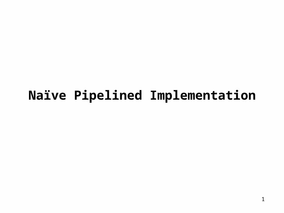
Problem of SEQ
• Too slow– Too many tasks needed to finish in one clock cycle
– Signals need long time to propagate through all of the stages
– The clock must run slowly enough
• Does not make good use of hardware units– Every unit is active for part of the total clock cycle
5
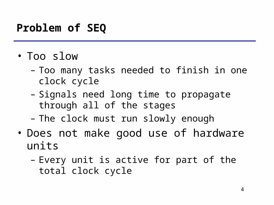
Real-World Pipelines: Car Washes
• Idea– Divide process into independent stages
– Move objects through stages in sequence
– At any given times, multiple objects being processed
Sequential Parallel
Pipelined
6
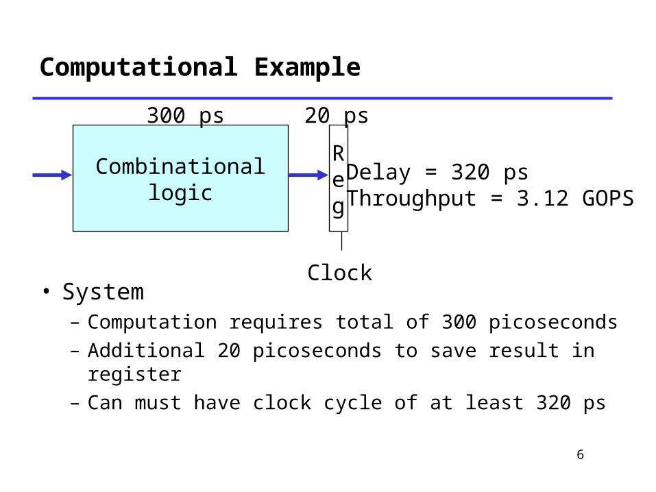
Computational Example
• System– Computation requires total of 300 picoseconds
– Additional 20 picoseconds to save result in register
– Can must have clock cycle of at least 320 ps
Combinationallogic
Reg
300 ps 20 ps
Clock
Delay = 320 psThroughput = 3.12 GOPS

7
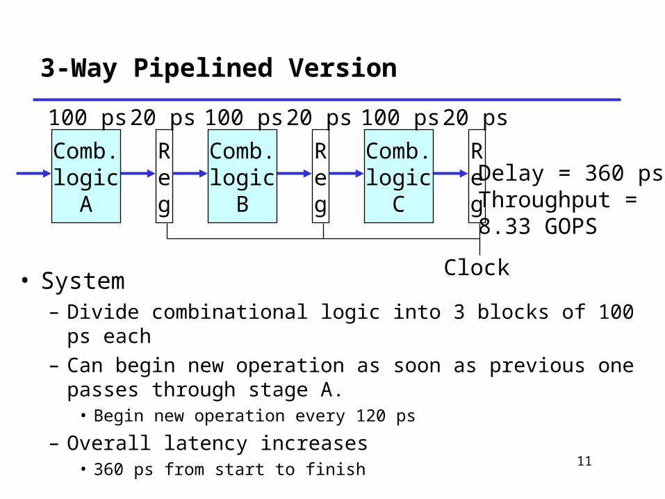
3-Way Pipelined Version
• System– Divide combinational logic into 3 blocks of 100 ps each
– Can begin new operation as soon as previous one passes through stage A.• Begin new operation every 120 ps
– Overall latency increases• 360 ps from start to finish
Reg
Clock
Comb.logic
A
Reg
Comb.logic
B
Reg
Comb.logic
C
100 ps 20 ps 100 ps 20 ps 100 ps 20 ps
Delay = 360 psThroughput = 8.33 GOPS
8
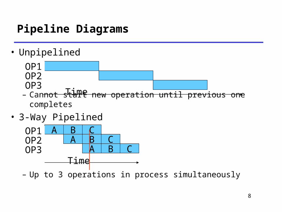
Pipeline Diagrams
• Unpipelined
– Cannot start new operation until previous one completes
• 3-Way Pipelined
– Up to 3 operations in process simultaneously
Time
OP1OP2OP3
Time
A B CA B C
A B C
OP1OP2OP3
9
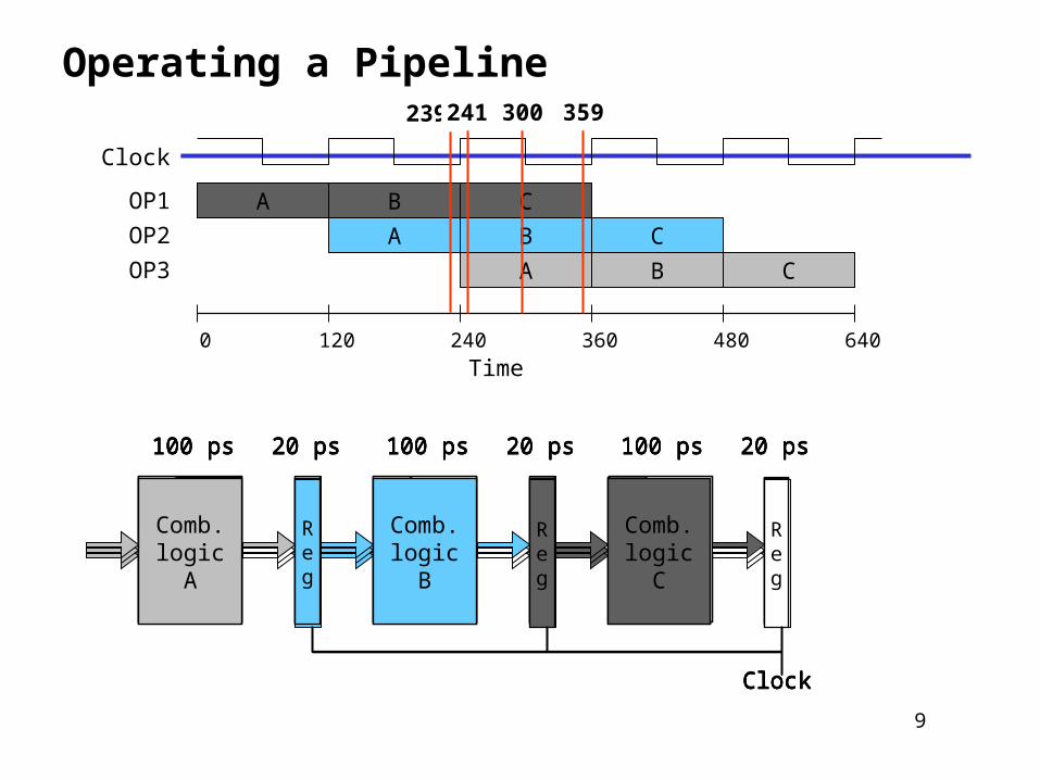
Operating a Pipeline
Time
OP1
OP2
OP3
A B C
A B C
A B C
0 120 240 360 480 640
Clock
Reg
Clock
Comb.logic
A
Reg
Comb.logic
B
Reg
Comb.logic
C
100 ps 20 ps 100 ps 20 ps 100 ps 20 ps
239
Reg
Clock
Comb.logic
A
Reg
Comb.logic
B
Reg
Comb.logic
C
100 ps 20 ps 100 ps 20 ps 100 ps 20 ps
241
Reg
Reg
Reg
100 ps 20 ps 100 ps 20 ps 100 ps 20 ps
Comb.logic
A
Comb.logic
B
Comb.logic
C
Clock
300
Reg
Clock
Comb.logic
A
Reg
Comb.logic
B
Reg
Comb.logic
C
100 ps 20 ps 100 ps 20 ps 100 ps 20 ps
359

10
Computational Example
• System– Computation requires total of 300 picoseconds
– Additional 20 picoseconds to save result in register
– Can must have clock cycle of at least 320 ps
Combinationallogic
Reg
300 ps 20 ps
Clock
Delay = 320 psThroughput = 3.12 GOPS
11
3-Way Pipelined Version
• System– Divide combinational logic into 3 blocks of 100 ps each
– Can begin new operation as soon as previous one passes through stage A.• Begin new operation every 120 ps
– Overall latency increases• 360 ps from start to finish
Reg
Clock
Comb.logic
A
Reg
Comb.logic
B
Reg
Comb.logic
C
100 ps 20 ps 100 ps 20 ps 100 ps 20 ps
Delay = 360 psThroughput = 8.33 GOPS
12
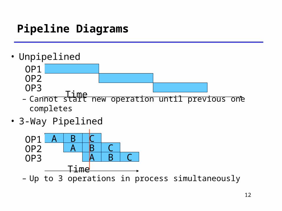
Pipeline Diagrams
• Unpipelined
– Cannot start new operation until previous one completes
• 3-Way Pipelined
– Up to 3 operations in process simultaneously
Time
OP1OP2OP3
Time
A B CA B C
A B C
OP1OP2OP3
13
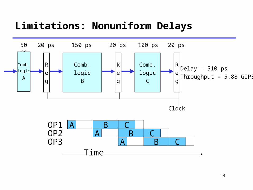
Limitations: Nonuniform Delays
Time
OP1OP2OP3
A B CA B C
A B C
R
e
g
Clock
R
e
g
Comb.
logic
B
R
e
g
Comb.
logic
C
50 ps 20 ps 150 ps 20 ps 100 ps 20 ps
Delay = 510 ps
Throughput = 5.88 GIPS
Comb.
logic
A
14
Limitations: Nonuniform Delays
• Throughput limited by slowest stage• Other stages sit idle for much of the time
• Challenging to partition system into balanced stages
15
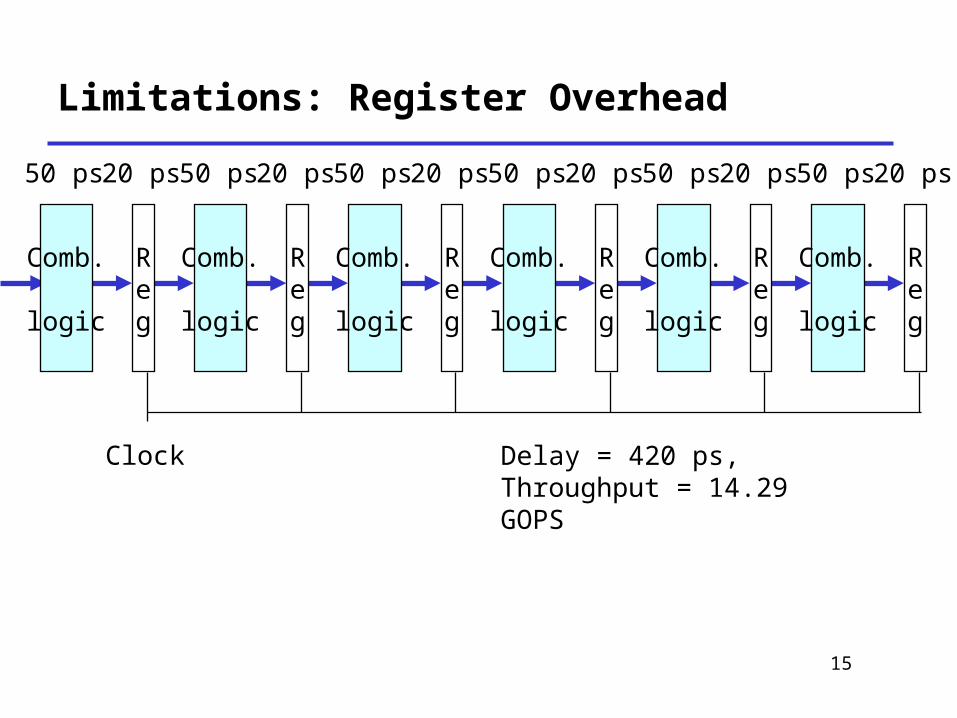
Limitations: Register Overhead
Delay = 420 ps, Throughput = 14.29 GOPS
Clock
Reg
Comb.
logic
50 ps 20 ps
Reg
Comb.
logic
50 ps 20 ps
Reg
Comb.
logic
50 ps 20 ps
Reg
Comb.
logic
50 ps 20 ps
Reg
Comb.
logic
50 ps 20 ps
Reg
Comb.
logic
50 ps 20 ps
16
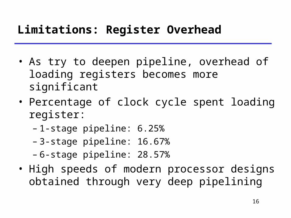
Limitations: Register Overhead
• As try to deepen pipeline, overhead of loading registers becomes more significant
• Percentage of clock cycle spent loading register:– 1-stage pipeline: 6.25% – 3-stage pipeline: 16.67% – 6-stage pipeline: 28.57%
• High speeds of modern processor designs obtained through very deep pipelining
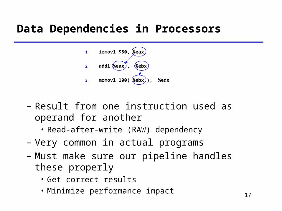
Data Dependencies in Processors
– Result from one instruction used as operand for another• Read-after-write (RAW) dependency
– Very common in actual programs– Must make sure our pipeline handles these properly• Get correct results• Minimize performance impact
1 irmovl $50, %eax
2 addl %eax , %ebx
3 mrmovl 100( %ebx ), %edx
17
18
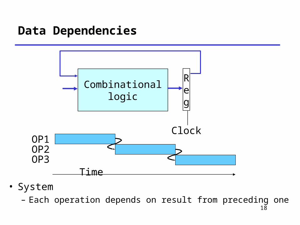
Data Dependencies
• System– Each operation depends on result from preceding one
Clock
Combinationallogic
Reg
Time
OP1OP2OP3
19
Data Hazards
Reg
Clock
Comb.logic
A
Reg
Comb.logic
B
Reg
Comb.logic
C
Time
OP1OP2OP3
A B CA B C
A B COP4 A B C
20
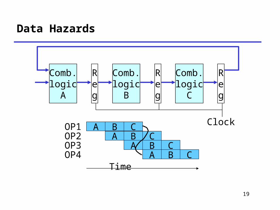
Data Hazards
• Result does not feed back around in time for next operation
• Pipelining has changed behavior of system
21
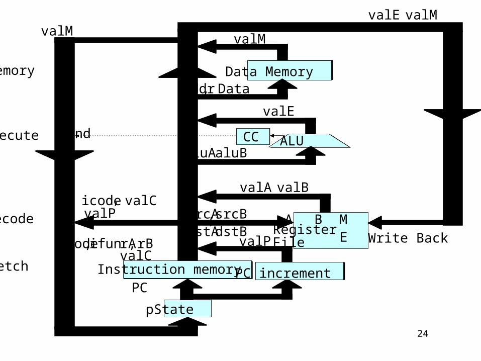
Naïve PIPE Implementation
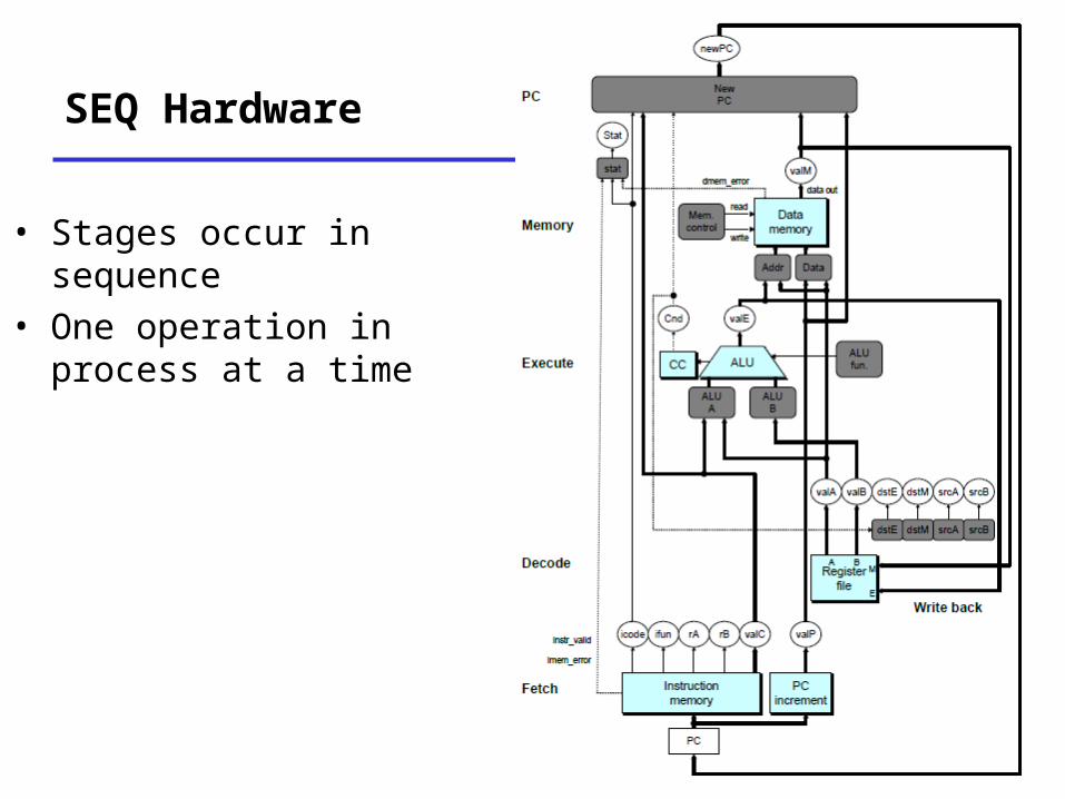
SEQ Hardware
• Stages occur in sequence
• One operation in process at a time
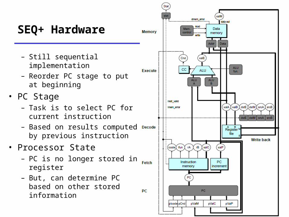
SEQ+ Hardware
– Still sequential implementation
– Reorder PC stage to put at beginning
• PC Stage– Task is to select PC for current instruction
– Based on results computed by previous instruction
• Processor State– PC is no longer stored in register
– But, can determine PC based on other stored information
24
Memory
Execute
Decode
Fetch Instruction memoryPC increment
CC ALU
Data Memory
icode, ifunrA, rBvalC
RegisterFile
A B ME
pState
valP
srcA, srcBdstA
, dstB
valA, valB
aluA, aluBCnd
valE
Addr, Data
valM
valE , valMvalM
icode, valCvalP
PC
Write Back
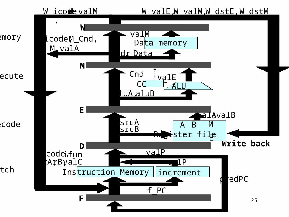
25
PC increment
CC ALU
Data memory
Write backvalP
d_srcBd_srcA
Register fileA B M
E
valA, valB
aluA,aluB
Cnd valE
Addr, Data
valM
W_valE,W_valM,W_dstE,W_dstMW_icode,
W_valM
Icode,ifunrA,rB,valC
E
M
W
F
D
valP
f_PCpredPC
Instruction Memory
M_icode,M_Cnd, M_valA
Memory
Execute
Decode
Fetch
26
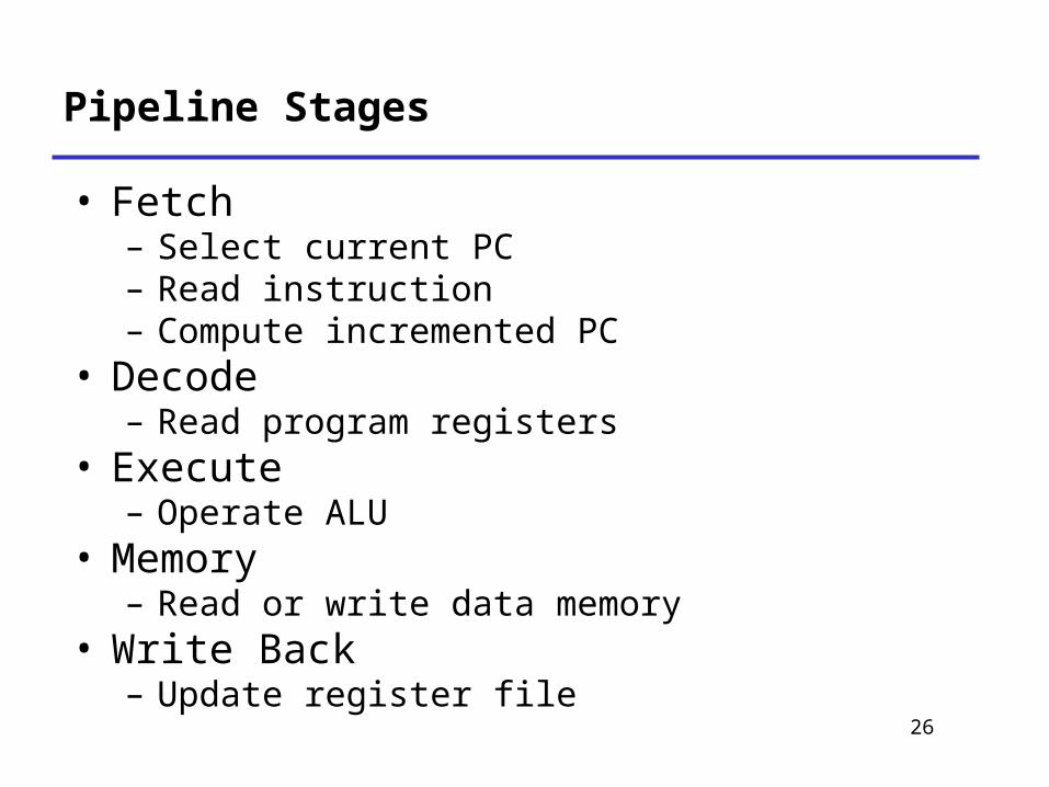
Pipeline Stages
• Fetch– Select current PC– Read instruction– Compute incremented PC
• Decode– Read program registers
• Execute– Operate ALU
• Memory– Read or write data memory
• Write Back– Update register file
27
PIPE- Hardware
• Pipeline registers hold intermediate values from instruction execution
• Forward (Upward) Paths– Values passed from one stage to next– Cannot jump past stages
• e.g., valC passes through decode
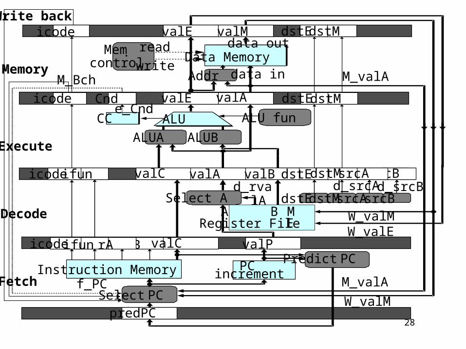
28
E
M
W
F
D
PCPC
ALU
Data Memory
Select PC
rB
Select A
ALUA ALUB
Mem.control
Addr
read
ALU fun
Fetch
Decode
Execute
Memory
Write back
data out
data in M_valA
W_valMW_valE
M_valA
W_valM
d_rvalA
f_PC
Predict PC
valE valM dstEdstM
Cnd valE valA dstEdstM
icodeifun valC valA valB dstE srcB
valC valPicodeifun rA
predPC
CCe_Cnd
M_Bchwrite
dstMsrcA
Register FileA B M
E
dstEdstMsrcAsrcBd_srcAd_srcB
InstructionInstruction Memory increment
icode
icode
29
E
M
W
F
D
PCPC
ALU
Data Memory
Select PC
rB
Select A
ALUA ALUB
Mem.control
Addr
read
ALU fun
Fetch
Decode
Execute
Memory
Write backicode
data out
data in M_valA
W_valMW_valE
M_valA
W_valM
d_rvalA
f_PC
Predict PC
valE valM dstEdstM
Cndicode valE valA dstEdstM
icodeifun valC valA valB dstE srcB
valC valPicodeifun rA
predPC
CCe_Cnd
M_Bchwrite
dstMsrcA
Register FileA B M
E
srcBsrcAdstMdstEd_srcAd_srcB
InstructionInstruction Memory increment

30
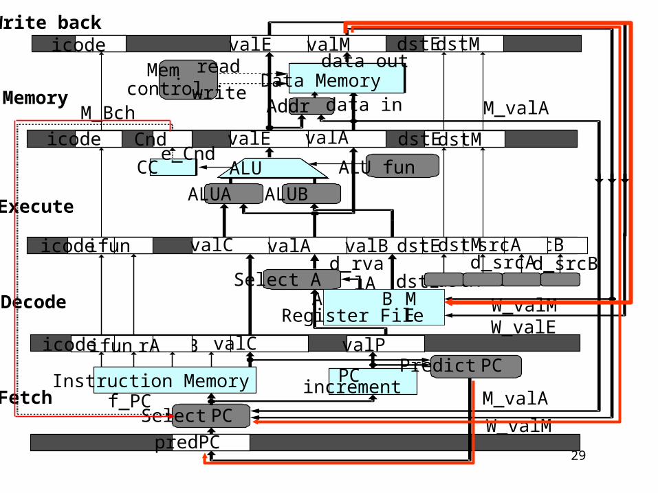
Feedback Paths
• Predicted PC– Guess value of next PC– Branch information
•Jump taken/not-taken•Fall-through or target address
– Return point•Read from memory
• Register updates•To register file write ports
31
• Start fetch of new instruction after current one has completed fetch stage– Not enough time to reliably determine next instruction
• Guess which instruction will follow– Recover if prediction was incorrect
Predicting the PC
32
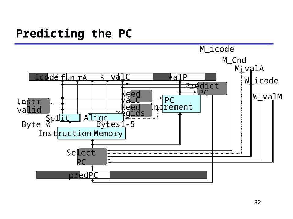
Predicting the PC
F
D
M_icode
PredictPC
InstructionInstruction Memory
PCincrement
predPC
Needregids
NeedvalCInstr
validAlignSplit
Bytes1-5Byte 0
SelectPC
M_CndM_valA
W_icode
W_valM
D rB valC valPicodeifun rA

33
Our Prediction Strategy
• Instructions that Don’t Transfer Control– Predict next PC to be valP– Always reliable
• Call and Unconditional Jumps– Predict next PC to be valC (destination)– Always reliable

34
Our Prediction Strategy
• Conditional Jumps– Predict next PC to be valC (destination)– Only correct if branch is taken
• Typically right 60% of time
• Return Instruction– Don’t try to predict

35
Fetch
Predict
PC
D rB valC valPicodeifun rA
F predPC
InstructionInstruction Memory PCPCincrement
Select PC M_valAW_valM
f_PCM_Cnd
M_icode W_icode
Select PC
Int F_predPC = [
f_icode in {IJXX, ICALL} : f_valC;
1: f_valP;
];
36
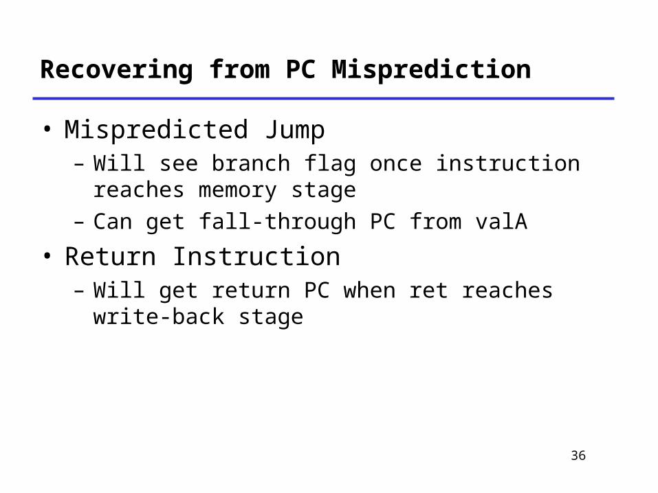
Recovering from PC Misprediction
• Mispredicted Jump– Will see branch flag once instruction reaches memory stage
– Can get fall-through PC from valA
• Return Instruction– Will get return PC when ret reaches write-back stage

37
Select PC
int f_PC = [
#mispredicted branch. Fetch at incremented PC
M_icode == IJXX && !M_Cnd : M_valA;
#completion of RET instruciton
W_icode == IRET : W_valM;
#default: Use predicted value of PC
1: F_predPC
];
38
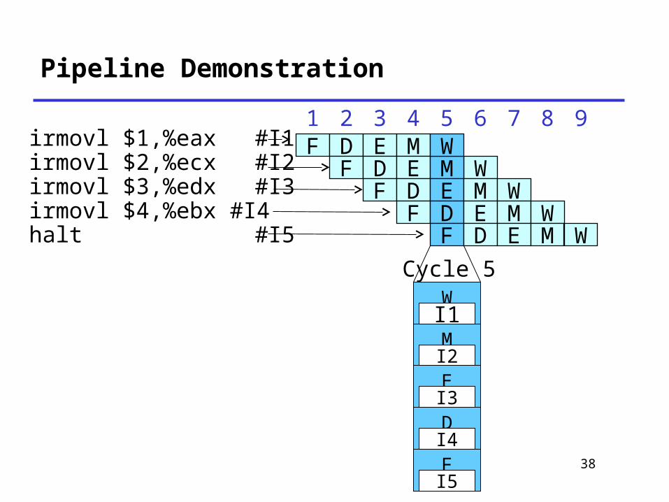
Pipeline Demonstration
1 2 3 4 5 6 7 8 9F D E M
WF D E MW
F D E M WF D E M W
F D E M W
Cycle 5WI1MI2EI3DI4FI5
irmovl $1,%eax #I1irmovl $2,%ecx #I2irmovl $3,%edx #I3irmovl $4,%ebx #I4halt #I5

39
Data Dependencies in Processors
• Result from one instruction used as operand for another– Read-after-write (RAW) dependency
• Very common in actual programs• Must make sure our pipeline handles these properly– Get correct results– Minimize performance impact
1 irmovl $50, %eax2 addl %eax , %ebx3 mrmovl 100(%ebx),%edx
40
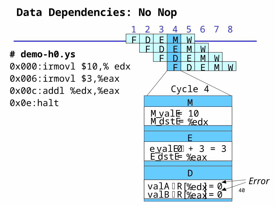
Data Dependencies: No Nop
1 2 3 4 5 6 7 8F D E M
WF D E MW
F D E M WF D E M W
E
DvalA R[%edx] = 0valB R[%eax] = 0
DvalA R[%edx] = 0valB R[%eax] = 0
Cycle 4
Error
MM_valE= 10M_dstE= %edx
e_valE 0 + 3 = 3 E_dstE= %eax
# demo-h0.ys0x000:irmovl $10,% edx0x006:irmovl $3,%eax0x00c:addl %edx,%eax0x0e:halt
41
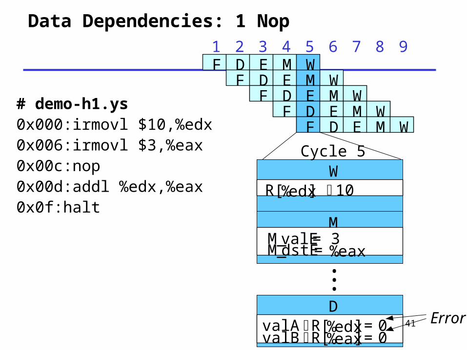
Data Dependencies: 1 Nop1 2 3 4 5 6 7 8 9F D E M
WF D E MW
F D E M WF D E M WF D E M WF D E M W
F D E M WF D E M W
WR[%edx] 10
WR[%edx] 10
DvalA R[%edx] = 0valB R[%eax] = 0
DvalA R[%edx] = 0valB R[%eax] = 0
•••
Cycle 5
Error
MM_valE= 3M_dstE= %eax
# demo-h1.ys0x000:irmovl $10,%edx0x006:irmovl $3,%eax0x00c:nop0x00d:addl %edx,%eax0x0f:halt

42
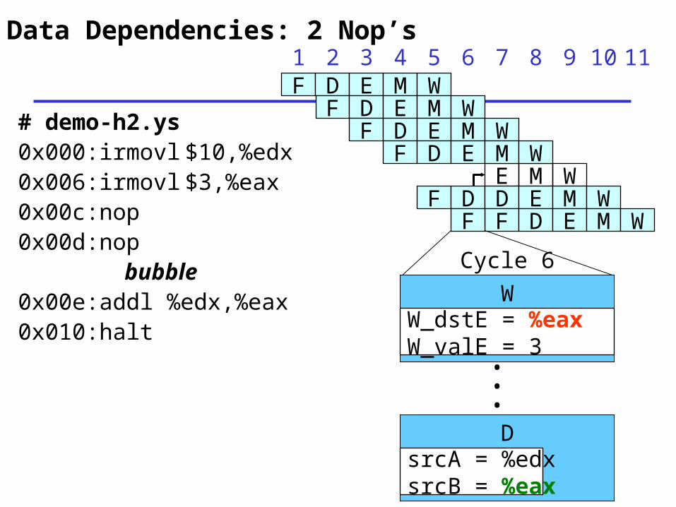
Data Dependencies: 2 Nop’s
1 2 3 4 5 6 7 8 9F D E M WF D E M W
F D E M WF D E M WF D E M WF D E M W
F D E M WF D E M WF D E M WF D E M W
F D E M WF D E M W
10
WR[%eax] 3
DvalA R[%edx] = 10valB R[%eax] = 0
•••
WR[%eax] 3
WR[%eax] 3
DvalA R[%edx] = 10valB R[%eax] = 0
DvalA R[%edx] = 10valB R[%eax] = 0
•••
Cycle 6
Error
# demo-h2.ys0x000:irmovl $10,%edx0x006:irmovl $3,%eax0x00c:nop0x00d:nop0x00e:addl %edx,%eax0x010:halt
43
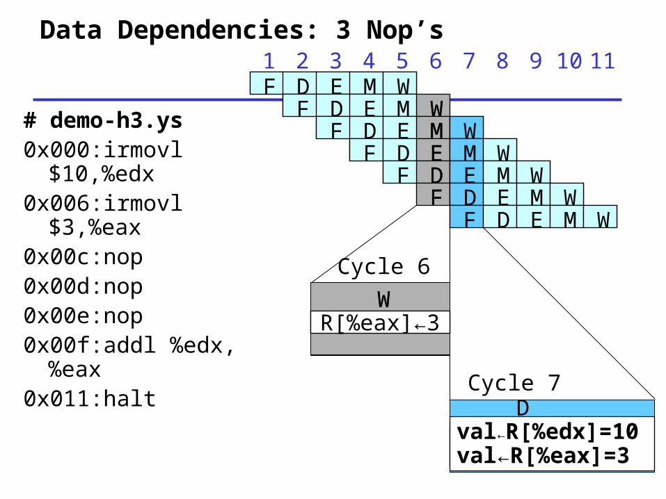
Data Dependencies: 3 Nop’s
DDval←R[%edx]=10val←R[%eax]=3
WWR[%eax]←3
Cycle 6
1 2 3 4 5 6 7 8 9F D E M WF D E M W
F D E M WF D E M WF D E M WF D E M W
F D E M WF D E M WF D E M WF D E M W
F D E M WF D E M W
10 11
F D E M WF D E M W
Cycle 7
# demo-h3.ys0x000:irmovl $10,%edx
0x006:irmovl $3,%eax
0x00c:nop0x00d:nop0x00e:nop0x00f:addl %edx,%eax
0x011:halt

44
Classes of Data Hazards
• Hazards can potentially occur when one instruction updates part of the program state that read by a later instruction
45
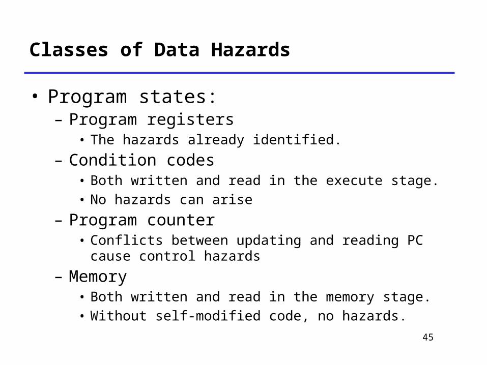
Classes of Data Hazards
• Program states:– Program registers
• The hazards already identified.
– Condition codes• Both written and read in the execute stage.• No hazards can arise
– Program counter• Conflicts between updating and reading PC cause control hazards
– Memory• Both written and read in the memory stage.• Without self-modified code, no hazards.
46
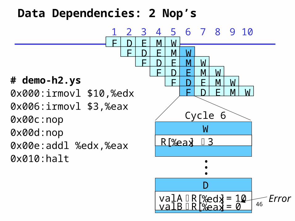
Data Dependencies: 2 Nop’s
1 2 3 4 5 6 7 8 9F D E M WF D E M W
F D E M WF D E M WF D E M WF D E M W
F D E M WF D E M WF D E M WF D E M W
F D E M WF D E M W
10
WR[%eax] 3
DvalA R[%edx] = 10valB R[%eax] = 0
•••
WR[%eax] 3
WR[%eax] 3
DvalA R[%edx] = 10valB R[%eax] = 0
DvalA R[%edx] = 10valB R[%eax] = 0
•••
Cycle 6
Error
# demo-h2.ys0x000:irmovl $10,%edx0x006:irmovl $3,%eax0x00c:nop0x00d:nop0x00e:addl %edx,%eax0x010:halt

47
Data Dependencies: 2 Nop’s
# demo-h2.ys0x000:irmovl $10,%edx0x006:irmovl $3,%eax0x00c:nop0x00d:nop
bubble0x00e:addl %edx,%eax0x010:halt
1 2 3 4 5 6 7 8 9F D E M W
F D E M WF D E M W
FE M W
D D E M WF D E M W
10
F
F D E M W
11
• If instruction follows too closely after one that writes register, slow it down
• Hold instruction in decode• Dynamically inject nop into execute stage

dstMdstE
48
E
M
W
F
D
PCPC
ALU
Data Memory
Select PC
rB
Select A
ALUA ALUB
Mem.control
Addr
read
ALU fun
Fetch
Decode
Execute
Memory
Write back
data out
data in M_valA
W_valMW_valE
M_valA
W_valM
d_rvalA
f_PC
Predict PC
valE valM dstEdstM
Bch valE valA dstEdstM
icodeifun valC valA valB dstE srcB
valC valPicodeifun rA
predPC
CCe_Bch
M_Bchwrite
dstMsrcA
Register FileA B M
E
srcAsrcBd_srcAd_srcB
InstructionInstruction Memory increment
icode
icode
49
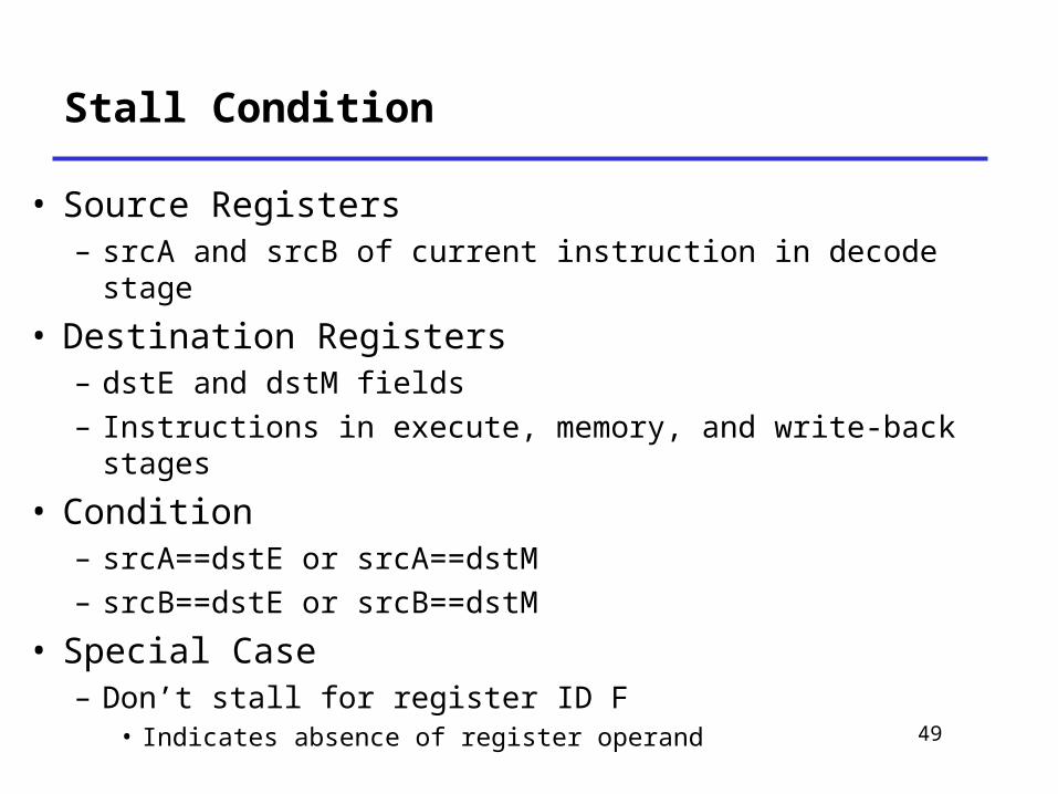
Stall Condition
• Source Registers– srcA and srcB of current instruction in decode stage
• Destination Registers– dstE and dstM fields– Instructions in execute, memory, and write-back stages
• Condition– srcA==dstE or srcA==dstM– srcB==dstE or srcB==dstM
• Special Case– Don’t stall for register ID F
• Indicates absence of register operand
50
Data Dependencies: 2 Nop’s
# demo-h2.ys0x000:irmovl $10,%edx0x006:irmovl $3,%eax0x00c:nop0x00d:nop
bubble0x00e:addl %edx,%eax0x010:halt
1 2 3 4 5 6 7 8 9F D E M W
F D E M WF D E M W
FE M W
D D E M WF D E M W
10
F
F D E M W
11
Cycle 6
W
D
•••
W_dstE = %eaxW_valE = 3
srcA = %edxsrcB = %eax
51
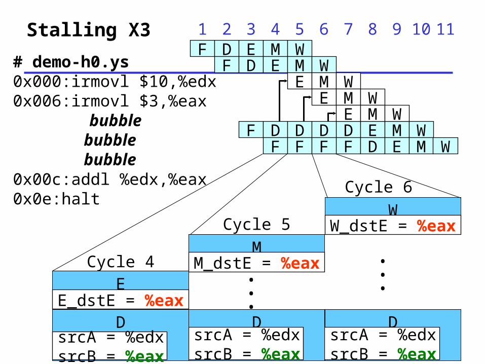
Stalling X3 1 2 3 4 5 6 7 8 9F D E M W
F D E M W
F
E M W
D
E M W
D D E M WF D E M W
10
F FDF
E M W
11
Cycle 4 •••
WW_dstE = %eax
DsrcA = %edxsrcB = %eax
•••
MM_dstE = %eax
DsrcA = %edxsrcB = %eax
EE_dstE = %eax
DsrcA = %edxsrcB = %eax
Cycle 5
Cycle 6
# demo-h0.ys0x000:irmovl $10,%edx0x006:irmovl $3,%eax
bubble bubble bubble
0x00c:addl %edx,%eax0x0e:halt
52
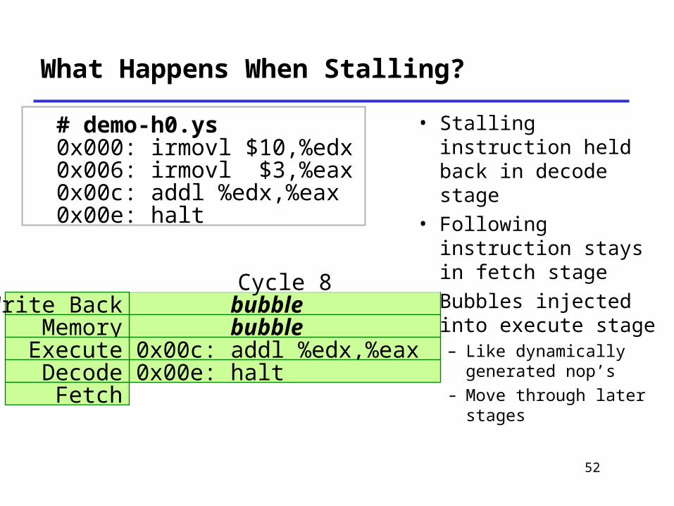
What Happens When Stalling?
• Stalling instruction held back in decode stage
• Following instruction stays in fetch stage
• Bubbles injected into execute stage– Like dynamically generated nop’s
– Move through later stages
0x000: irmovl $10,%edx0x006: irmovl $3,%eax0x00c: addl %edx,%eax
Cycle 4
0x00e: halt
0x000: irmovl $10,%edx0x006: irmovl $3,%eax0x00c: addl %edx,%eax
# demo-h0.ys
0x00e: halt
0x000: irmovl $10,%edx0x006: irmovl $3,%eax bubble0x00c: addl %edx,%eax
Cycle 5
0x00e: halt
0x006: irmovl $3,%eax bubble
0x00c: addl %edx,%eax bubble
Cycle 6
0x00e: halt
bubble bubble
0x00c: addl %edx,%eax bubble
Cycle 7
0x00e: halt
bubble bubble
Cycle 8
0x00c: addl %edx,%eax0x00e: halt
Write BackMemoryExecuteDecodeFetch
53
Implementing Stalling
• Pipeline Control– Combinational logic detects stall condition
– Sets mode signals for how pipeline registers should update
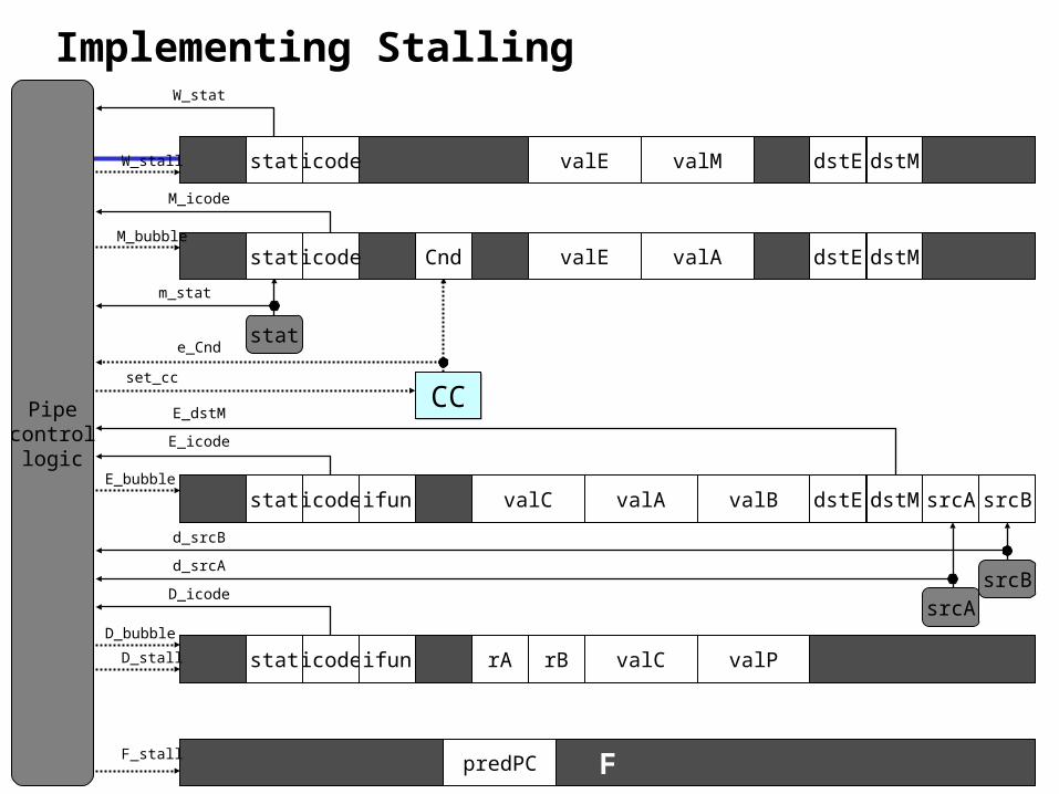
Implementing Stalling
E
M
W
F
D
CCCC
rB
srcAsrcB
icode valE valM dstE dstM
Cndicode valE valA dstE dstM
icodeifun valC valA valB dstE dstM srcA srcB
valC valPicodeifun rA
predPC
d_srcB
d_srcA
e_Cnd
D_icode
E_icode
M_icode
E_dstMPipecontrollogic
D_bubble
D_stall
E_bubble
F_stall
M_bubble
W_stall
set_cc
stat
stat
stat
stat
W_stat
stat
m_stat

55
Pipeline Register Modes
RisingclockRisingclock Output = x
xx
Output = xInput = y
stall = 1
bubble= 0
xxStall

56
Pipeline Register Modes
nop
RisingclockRisingclock Output = nop
xx
Output = xInput = y
stall = 0
bubble= 1
Bubble

57
Pipeline Register Modes
RisingclockRisingclock Output = y
yy
Output = xInput = y
stall = 0
bubble= 0
xxNormal
Next
• Data Forwarding
• Handle Control Hazard
• Performance matrix
• Suggested Reading 4.5
58