Embed Size (px)
Citation preview
RAV4 – OUTLINE OF NEW FEATURES
RAV4
1
OUTLINE OF NEW FEATURES
The following changes are made for the 2009 model year.
1. Model Line-up
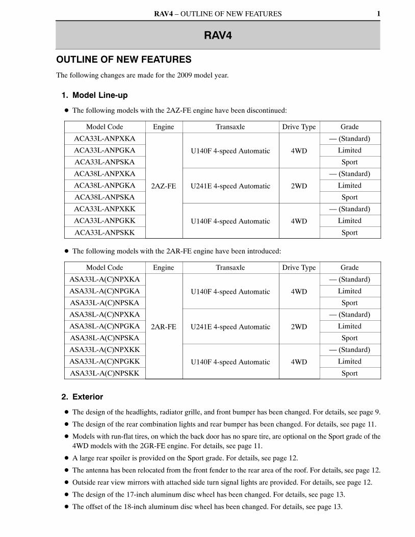
� The following models with the 2AZ-FE engine have been discontinued:
Model Code Engine Transaxle Drive Type Grade
ACA33L-ANPXKA
2AZ-FE
U140F 4-speed Automatic 4WD
— (Standard)
ACA33L-ANPGKA Limited
ACA33L-ANPSKA Sport
ACA38L-ANPXKA
U241E 4-speed Automatic 2WD
— (Standard)
ACA38L-ANPGKA Limited
ACA38L-ANPSKA Sport
ACA33L-ANPXKK
U140F 4-speed Automatic 4WD
— (Standard)
ACA33L-ANPGKK Limited
ACA33L-ANPSKK Sport
� The following models with the 2AR-FE engine have been introduced:
Model Code Engine Transaxle Drive Type Grade
ASA33L-A(C)NPXKA
2AR-FE
U140F 4-speed Automatic 4WD
— (Standard)
ASA33L-A(C)NPGKA Limited
ASA33L-A(C)NPSKA Sport
ASA38L-A(C)NPXKA
U241E 4-speed Automatic 2WD
— (Standard)
ASA38L-A(C)NPGKA Limited
ASA38L-A(C)NPSKA Sport
ASA33L-A(C)NPXKK
U140F 4-speed Automatic 4WD
— (Standard)
ASA33L-A(C)NPGKK Limited
ASA33L-A(C)NPSKK Sport
2. Exterior
� The design of the headlights, radiator grille, and front bumper has been changed. For details, see page 9.
� The design of the rear combination lights and rear bumper has been changed. For details, see page 11.
� Models with run-flat tires, on which the back door has no spare tire, are optional on the Sport grade of the4WD models with the 2GR-FE engine. For details, see page 11.
� A large rear spoiler is provided on the Sport grade. For details, see page 12.
� The antenna has been relocated from the front fender to the rear area of the roof. For details, see page 12.
� Outside rear view mirrors with attached side turn signal lights are provided. For details, see page 12.
� The design of the 17-inch aluminum disc wheel has been changed. For details, see page 13.
� The offset of the 18-inch aluminum disc wheel has been changed. For details, see page 13.
RAV4 – OUTLINE OF NEW FEATURES
10SMO18Y
Side Register Fin
’09 RAV4 ’08 RAV4
Escutcheon
Side Register
Console Garnish
Console Pocket
2
� The following exterior colors are available, including 4 new colors:
Color No. Color Name Note
040 Super White II Carryover
070 White Pearl Crystal Shine Carryover
1F7 Silver Metallic Carryover
1G3 Gray Metallic New
202 Black Carryover
3R3 Red Mica Metallic Carryover
4T3 Bronze Mica Metallic New
4T8 Beige Metallic New
6T3 Dark Green Mica Carryover
8R3 Grayish Blue Metallic Carryover
9AF Dark Violet Mica Metallic New
3. Interior
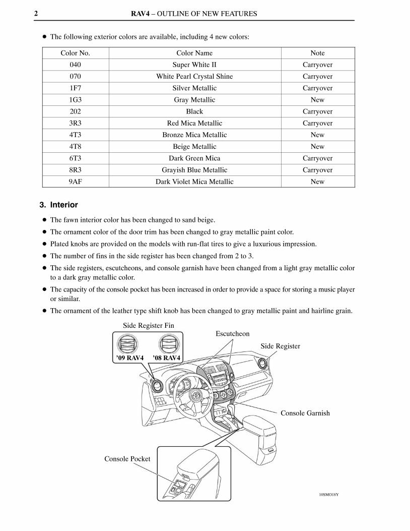
� The fawn interior color has been changed to sand beige.
� The ornament color of the door trim has been changed to gray metallic paint color.
� Plated knobs are provided on the models with run-flat tires to give a luxurious impression.
� The number of fins in the side register has been changed from 2 to 3.
� The side registers, escutcheons, and console garnish have been changed from a light gray metallic colorto a dark gray metallic color.
� The capacity of the console pocket has been increased in order to provide a space for storing a music playeror similar.
� The ornament of the leather type shift knob has been changed to gray metallic paint and hairline grain.

RAV4 – OUTLINE OF NEW FEATURES 3
4. 2AR-FE Engine
A newly developed 2AR-FE engine has been added instead of the 2AZ-FE engine. For details, see page 14.
5. 2GR-FE Engine
A permanent DTC is used for the DTCs associated with the illumination of the MIL. The permanent DTCscan not be cleared by using the Techstream, disconnecting the battery terminal, or removing the EFI fuse.For details of the method to clear the DTCs, refer to the 2009 RAV4 Repair Manual (Pub No. RM10S0U).
6. U140F and U241E Automatic Transaxles
� U140F and U241E automatic transaxles are used on models with the 2AR-FE engine.
� A compact and lightweight ATF warmer is used.
� A permanent DTC is used for the DTCs associated with the illumination of the MIL. The permanent DTCscan not be cleared by using the Techstream, disconnecting the battery terminal, or removing the EFI fuse.For details of the method to clear the DTCs, refer to the 2009 RAV4 Repair Manual (Pub No. RM10S0U).
7. U151E and U151F Automatic Transaxles
A permanent DTC is used for the DTCs associated with the illumination of the MIL. The permanent DTCscan not be cleared by using the Techstream, disconnecting the battery terminal, or removing the EFI fuse.For details of the method to clear the DTCs, refer to the 2009 RAV4 Repair Manual (Pub No. RM10SU).
8. Suspension and Axle
A separate input construction type upper support is used in the front suspension of all models. For details ofthe separate input construction type upper support, refer to the 2006 RAV4 New Car Features (NM01M0U).
9. Brake Control System
� A compact and lightweight brake actuator is used.
� A VSC OFF switch is used.
For details, see page 103.
10. EPS (Electric Power Steering)
Battery voltage drop suppression control is used in the EPS (Electric Power Steering) system. For details,see page 106.
RAV4 – OUTLINE OF NEW FEATURES
10SBO001Y
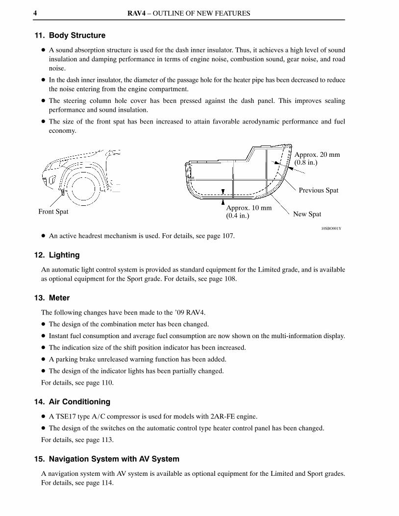
Front Spat Approx. 10 mm (0.4 in.)
Approx. 20 mm (0.8 in.)
Previous Spat
New Spat
4
11. Body Structure
� A sound absorption structure is used for the dash inner insulator. Thus, it achieves a high level of soundinsulation and damping performance in terms of engine noise, combustion sound, gear noise, and roadnoise.
� In the dash inner insulator, the diameter of the passage hole for the heater pipe has been decreased to reducethe noise entering from the engine compartment.
� The steering column hole cover has been pressed against the dash panel. This improves sealingperformance and sound insulation.
� The size of the front spat has been increased to attain favorable aerodynamic performance and fueleconomy.
� An active headrest mechanism is used. For details, see page 107.
12. Lighting
An automatic light control system is provided as standard equipment for the Limited grade, and is availableas optional equipment for the Sport grade. For details, see page 108.
13. Meter
The following changes have been made to the ’09 RAV4.
� The design of the combination meter has been changed.
� Instant fuel consumption and average fuel consumption are now shown on the multi-information display.
� The indication size of the shift position indicator has been increased.
� A parking brake unreleased warning function has been added.
� The design of the indicator lights has been partially changed.
For details, see page 110.
14. Air Conditioning
� A TSE17 type A/C compressor is used for models with 2AR-FE engine.
� The design of the switches on the automatic control type heater control panel has been changed.
For details, see page 113.
15. Navigation System with AV System
A navigation system with AV system is available as optional equipment for the Limited and Sport grades.For details, see page 114.
RAV4 – OUTLINE OF NEW FEATURES
10SBE38Y
Sliding Roof Switch
5
16. Rear View Monitor System
A rear view monitor system is available as optional equipment for the Limited and Sport grades. For details,see page 120.
17. Wireless Door Lock Control System
In the customized body electronics system, the setting of the automatic lock time function has been changedas follows:
SystemTechstream
Display ContentContent Model
DefaultSetting
AvailableSetting
Wireless DoorLock ControlSystem
Auto Lock Time
Function to change the timeuntil relocking afterunlocking with the wirelessdoor lock.
’09 RAV4 60
30,60,120
or OFF
’08 RAV4 30 30 or 60
For details, refer to the 2009 RAV4 Repair Manual (Pub. No. RM10S0U).
18. Smart Key System
A smart key system is used for the Limited grade. For details, see page 123.
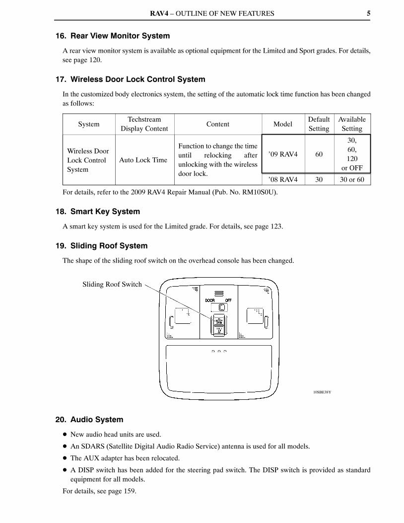
19. Sliding Roof System
The shape of the sliding roof switch on the overhead console has been changed.
20. Audio System
� New audio head units are used.
� An SDARS (Satellite Digital Audio Radio Service) antenna is used for all models.
� The AUX adapter has been relocated.
� A DISP switch has been added for the steering pad switch. The DISP switch is provided as standardequipment for all models.
For details, see page 159.
RAV4 – OUTLINE OF NEW FEATURES
10SBE37Y
Power Outlet Main Switch
Power Outlet Socket(For AC Power Supply)
6
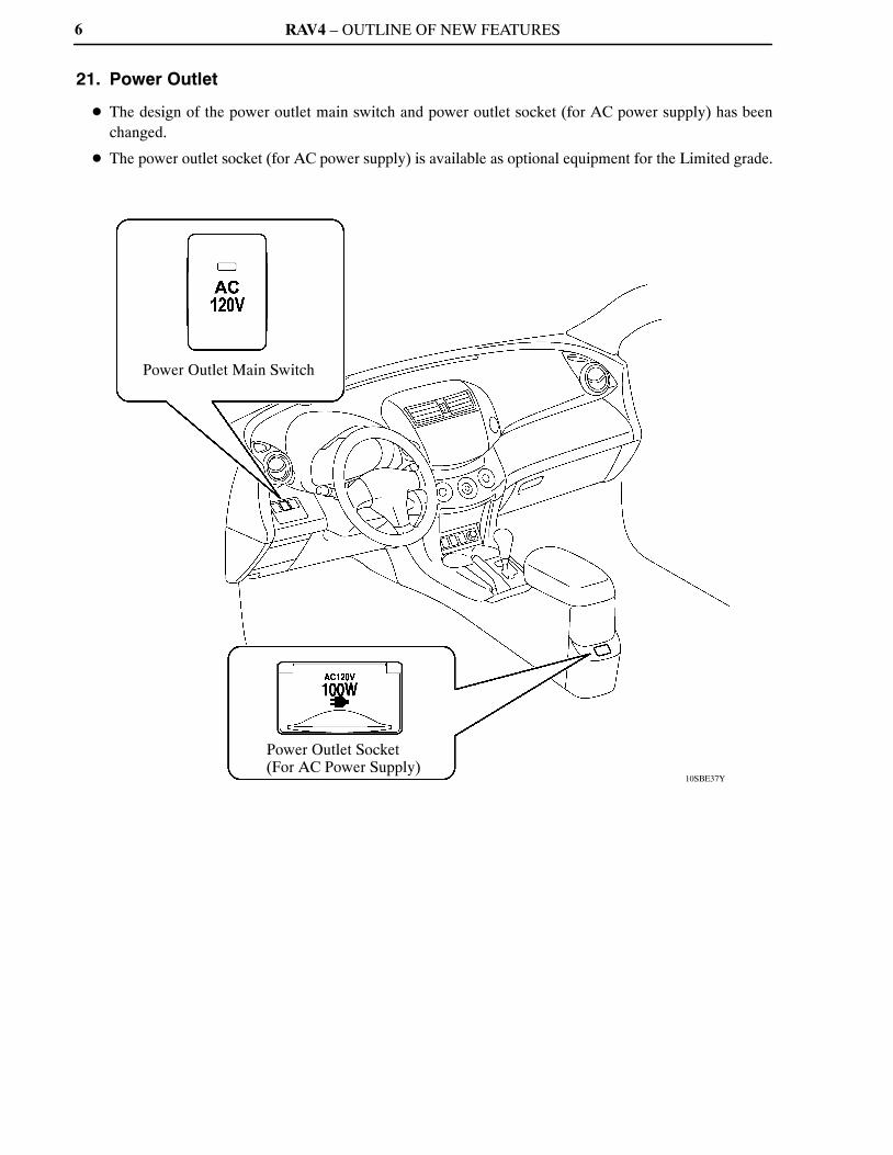
21. Power Outlet
� The design of the power outlet main switch and power outlet socket (for AC power supply) has beenchanged.
� The power outlet socket (for AC power supply) is available as optional equipment for the Limited grade.

RAV4 – MODEL CODE
ASA33 L – A N P X K A1 2 3 4 5 6 7 8
1
BASIC MODEL CODECODE
2STEERING WHEEL POSITIONL: Left-hand Drive
4BODY TYPEN: 5-door Wagon
5GEAR SHIFT TYPEP: 4-speed Automatic, FloorA: 5-speed Automatic, Floor
6
GRADEX: — (Standard)G: LimitedS: Sport
8DESTINATIONA: U.S.A.K: Canada
3MODEL NAMEA: RAV4 (Produced by TMC*1)C: RAV4 (Produced by TMMC*2)
7ENGINE SPECIFICATIONK: DOHC and SFI
ASA33ASA38GSA33
GSA38
ENGINE
2AR-FE
2GR-FE
DRIVE TYPE4WD2WD4WD
2WD
7
MODEL CODE
*1: TMC: Toyota Motor Corporation*2: TMMC: Toyota Motor Manufacturing Canada, Inc.
RAV4 – MODEL LINE-UP8
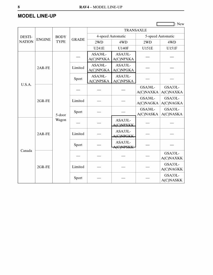
MODEL LINE-UP
: New
DESTI-NATION
ENGINEBODYTYPE
GRADE
TRANSAXLE
4-speed Automatic 5-speed Automatic
2WD 4WD 2WD 4WD
U241E U140F U151E U151F
U.S.A.
2AR-FE
5-doorWagon
—ASA38L-
A(C)NPXKAASA33L-
A(C)NPXKA— —
LimitedASA38L-
A(C)NPGKAASA33L-
A(C)NPGKA— —
SportASA38L-
A(C)NPSKAASA33L-
A(C)NPSKA— —
2GR-FE
— — —GSA38L-
A(C)NAXKAGSA33L-
A(C)NAXKA
Limited — —GSA38L-
A(C)NAGKAGSA33L-
A(C)NAGKA
Sport — —GSA38L-
A(C)NASKAGSA33L-
A(C)NASKA
Canada
2AR-FE
— —ASA33L-
A(C)NPXKK— —
Limited —ASA33L-
A(C)NPGKK— —
Sport —ASA33L-
A(C)NPSKK— —
2GR-FE
— — — —GSA33L-
A(C)NAXKK
Limited — — —GSA33L-
A(C)NAGKK
Sport — — —GSA33L-
A(C)NASKK

RAV4 – NEW FEATURES
10SMO04Y10SMO02Y
10SMO03Y
’09 RAV4 Standard and Sport Grades
’08 RAV4
’09 RAV4 Limited Grade
9
NEW FEATURES
�EXTERIOR
1. Front Design
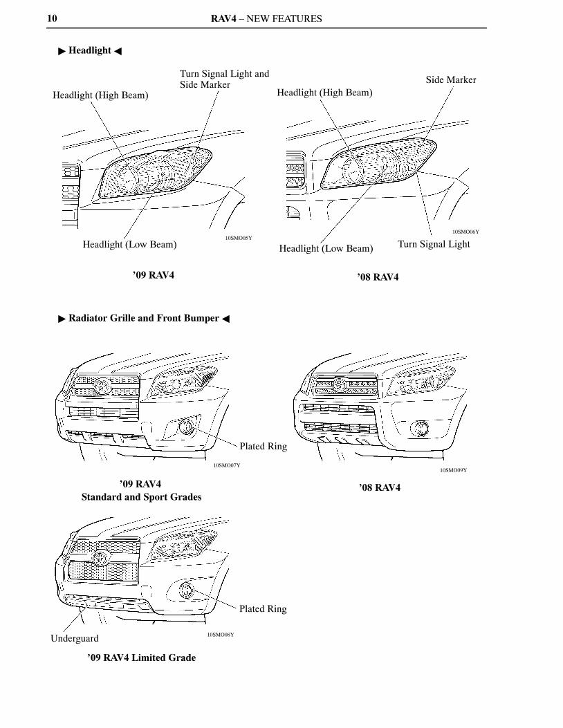
� 2 types of design are provided for the front bumper and radiator grille. The front design of the Limitedgrade consists of a large-size radiator grille and an underguard in order to differentiate it from the standardand Sport grades.
� A newly designed headlight incorporating a front side turn signal light and a side marker within the samelens is used.
� The models with fog lights use plated rings for a luxurious look.
RAV4 – NEW FEATURES
10SMO06Y10SMO05Y
Headlight (High Beam)
Turn Signal Light and Side Marker
Headlight (Low Beam)
’09 RAV4
Headlight (High Beam)Side Marker
Headlight (Low Beam) Turn Signal Light
’08 RAV4
10SMO09Y10SMO07Y
10SMO08Y
’09 RAV4 Standard and Sport Grades
Plated Ring
’08 RAV4
Underguard
Plated Ring
’09 RAV4 Limited Grade
10
� Headlight �
� Radiator Grille and Front Bumper �

RAV4 – NEW FEATURES
10SMO12Y10SMO10Y
10SMO11Y
’09 RAV4 ’08 RAV4
’09 RAV4 with Run-flat Tire
Plated TypeLicense Garnish
11
2. Rear Design
� The shape of the rear bumper has been changed. In addition, it is provided with a material portion towithstand abrasion during loading and unloading of cargo.
� On the models with the run-flat tires, the back door is designed without a spare tire. A license garnish isprovided on the models with the run-flat tires. The license garnish uses plating at the bottom for a luxuriouslook.
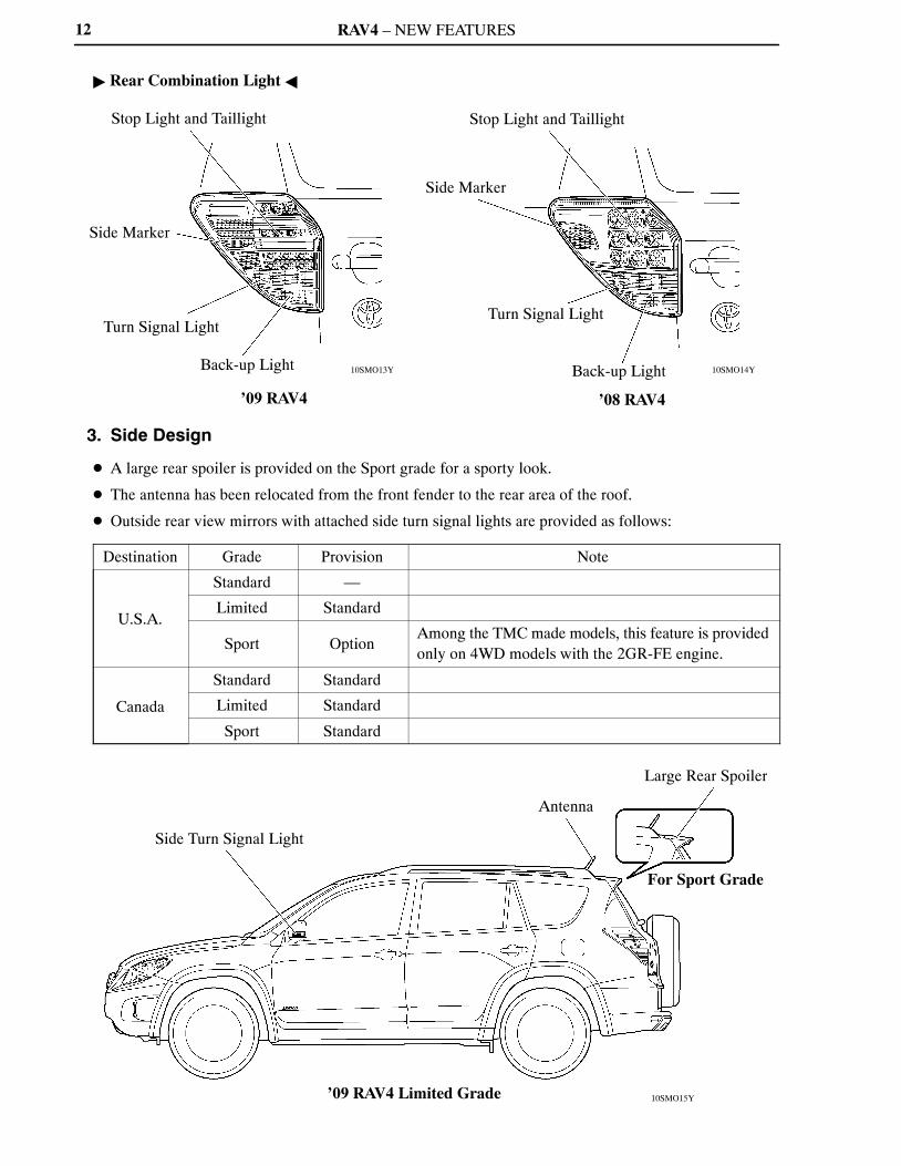
� Newly designed rear combination lights are provided with 12 LEDs (Light Emitting Diodes) in thetaillights and stop lights.
RAV4 – NEW FEATURES
10SMO14Y10SMO13Y
Stop Light and Taillight
Side Marker
Turn Signal Light
Back-up Light
’09 RAV4
Stop Light and Taillight
Side Marker
Turn Signal Light
Back-up Light
’08 RAV4
10SMO15Y
Side Turn Signal Light
Antenna
Large Rear Spoiler
For Sport Grade
’09 RAV4 Limited Grade
12
� Rear Combination Light �
3. Side Design
� A large rear spoiler is provided on the Sport grade for a sporty look.
� The antenna has been relocated from the front fender to the rear area of the roof.
� Outside rear view mirrors with attached side turn signal lights are provided as follows:
Destination Grade Provision Note
U.S.A.
Standard —
Limited Standard
Sport OptionAmong the TMC made models, this feature is providedonly on 4WD models with the 2GR-FE engine.
Canada
Standard Standard
Limited Standard
Sport Standard
RAV4 – NEW FEATURES
10SMO17Y10SMO16Y
01NMO13Y01NMO13Y
13
4. Tire and Disc Wheel
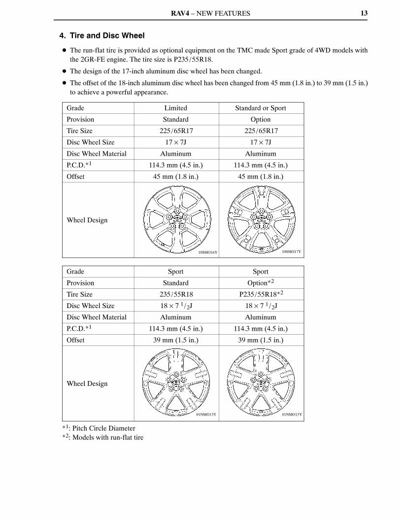
� The run-flat tire is provided as optional equipment on the TMC made Sport grade of 4WD models withthe 2GR-FE engine. The tire size is P235/55R18.
� The design of the 17-inch aluminum disc wheel has been changed.
� The offset of the 18-inch aluminum disc wheel has been changed from 45 mm (1.8 in.) to 39 mm (1.5 in.)to achieve a powerful appearance.
Grade Limited Standard or Sport
Provision Standard Option
Tire Size 225/65R17 225/65R17
Disc Wheel Size 17 × 7J 17 × 7J
Disc Wheel Material Aluminum Aluminum
P.C.D.*1 114.3 mm (4.5 in.) 114.3 mm (4.5 in.)
Offset 45 mm (1.8 in.) 45 mm (1.8 in.)
Wheel Design
Grade Sport Sport
Provision Standard Option*2
Tire Size 235/55R18 P235/55R18*2
Disc Wheel Size 18 × 7 1/2J 18 × 7 1/2J
Disc Wheel Material Aluminum Aluminum
P.C.D.*1 114.3 mm (4.5 in.) 114.3 mm (4.5 in.)
Offset 39 mm (1.5 in.) 39 mm (1.5 in.)
Wheel Design
*1: Pitch Circle Diameter*2: Models with run-flat tire
RAV4 – NEW FEATURES
10SEG01Y
10SEG02Y
14
�2AR-FE ENGINE
1. General
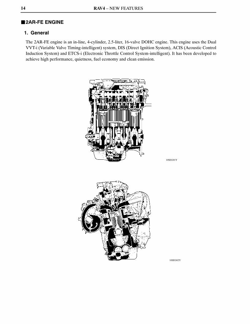
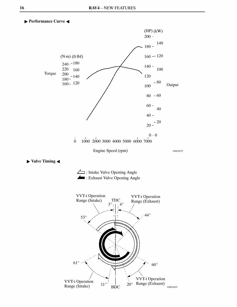
The 2AR-FE engine is an in-line, 4-cylinder, 2.5-liter, 16-valve DOHC engine. This engine uses the DualVVT-i (Variable Valve Timing-intelligent) system, DIS (Direct Ignition System), ACIS (Acoustic ControlInduction System) and ETCS-i (Electronic Throttle Control System-intelligent). It has been developed toachieve high performance, quietness, fuel economy and clean emission.

RAV4 – NEW FEATURES 15
� Engine Specifications �
Model ’09 RAV 4 ’08 RAV4
Engine 2AR-FE 2AZ-FE
No. of Cyls. & Arrangement 4-cylinder, In-line �
Valve Mechanism16-valve DOHC, Chain Drive
(with Dual VVT-i)16-valve DOHC, Chain Drive
(with VVT-i)
Combustion Chamber Pentroof Type �
Manifolds Cross-flow �
Fuel System SFI �
Ignition System DIS �
Displacement2494 cm3
(152.2 cu.in.)2362 cm3
(144.1 cu. in.)
Bore × Stroke90.0 × 98.0 mm(3.54 × 3.86 in.)
88.5 × 96.0 mm(3.48 × 3.78 in.)
Compression Ratio 10.4 : 1 9.8 : 1
Max. Output*1 (SAE-NET)134 kW @ 6000 rpm
(180 HP @ 6000 rpm)124 kW @ 6000 rpm
(166 HP @ 6000 rpm)
Max. Torque*1 (SAE-NET)235 N⋅m @ 4100 rpm
(173 ft⋅lbf @ 4100 rpm)224 N⋅m @ 4000 rpm
(165 ft⋅lbf @ 4000 rpm)
ValveTiming
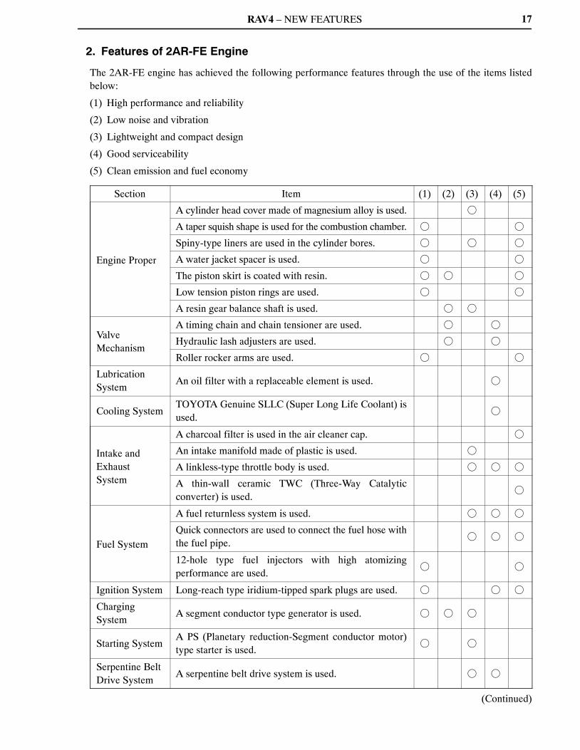
IntakeOpen 3� – 53� BTDC 3� – 43� BTDC
Closed 61� – 11� ABDC 65� – 25� ABDC
ExhaustOpen 60� – 20� BBDC 45� BBDC
Closed 4� – 44� ATDC 3� ATDC
Firing Order 1 – 3 – 4 – 2 �
Research Octane Number 91 or higher �
Octane Rating 87 or higher �
Tailpipe Emission Regulation ULEV-II, SFTP �
Evaporative Emission Regulation LEV-II, ORVR �
Engine Service Mass (Reference) *2 147 kg (324.0 lb) 138 kg (304.2 lb)
*1: Maximum output and torque rating is determined by revised SAE J1349 standard.*2: Weight shows the figure with oil and engine coolant fully filled.
RAV4 – NEW FEATURES
10SEG03Y
Torque
(N.m)
240220200180160
(ft.lbf)
180
160
140
120
(HP)200
180
160
140
120
100
80
60
40
20
0
(kW)
140
120
100
80
60
40
20
0
Output
0 1000 2000 3000 4000 5000 6000 7000
Engine Speed (rpm)
10SEG04Y
: Intake Valve Opening Angle: Exhaust Valve Opening Angle
VVT-i Operation Range (Intake)
53�
61�
VVT-i Operation Range (Intake) 11�
TDC3� 4�
VVT-i Operation Range (Exhaust)
44�
60�
VVT-i Operation Range (Exhaust)20�
BDC
16
� Performance Curve �
� Valve Timing �
RAV4 – NEW FEATURES 17
2. Features of 2AR-FE Engine
The 2AR-FE engine has achieved the following performance features through the use of the items listedbelow:
(1) High performance and reliability
(2) Low noise and vibration
(3) Lightweight and compact design
(4) Good serviceability
(5) Clean emission and fuel economy
Section Item (1) (2) (3) (4) (5)
Engine Proper
A cylinder head cover made of magnesium alloy is used. �
A taper squish shape is used for the combustion chamber. � �
Spiny-type liners are used in the cylinder bores. � � �
A water jacket spacer is used. � �
The piston skirt is coated with resin. � � �
Low tension piston rings are used. � �
A resin gear balance shaft is used. � �
ValveMechanism
A timing chain and chain tensioner are used. � �
Hydraulic lash adjusters are used. � �
Roller rocker arms are used. � �
LubricationSystem
An oil filter with a replaceable element is used. �
Cooling SystemTOYOTA Genuine SLLC (Super Long Life Coolant) isused.
�
Intake andExhaustSystem
A charcoal filter is used in the air cleaner cap. �
An intake manifold made of plastic is used. �
A linkless-type throttle body is used. � � �
A thin-wall ceramic TWC (Three-Way Catalyticconverter) is used.
�
Fuel System
A fuel returnless system is used. � � �
Quick connectors are used to connect the fuel hose withthe fuel pipe.
� � �
12-hole type fuel injectors with high atomizingperformance are used.
� �
Ignition System Long-reach type iridium-tipped spark plugs are used. � � �
ChargingSystem
A segment conductor type generator is used. � � �
Starting SystemA PS (Planetary reduction-Segment conductor motor)type starter is used.
� �
Serpentine BeltDrive System
A serpentine belt drive system is used. � �
(Continued)

RAV4 – NEW FEATURES18
Section Item (1) (2) (3) (4) (5)
Engine ControlSystem
The DIS (Direct Ignition System) makes ignition timingadjustment unnecessary.
� � �
An ETCS-i (Electronic Throttle ControlSystem-intelligent) is used.
� �
A Dual VVT-i (Variable Valve Timing-intelligent)system is used.
� �
An ACIS (Acoustic Control Induction System) is used. � �
A tumble control system is used. � �
A starter control (cranking hold function) is used.* �
*: Models with smart key system
RAV4 – NEW FEATURES
10SEG08Y
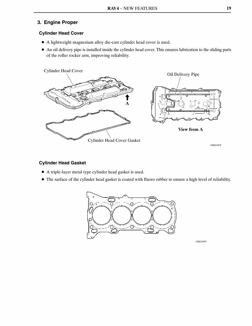
Cylinder Head Cover
A
Cylinder Head Cover Gasket
Oil Delivery Pipe
View from A
10SEG09Y
19
3. Engine Proper
Cylinder Head Cover
� A lightweight magnesium alloy die-cast cylinder head cover is used.
� An oil delivery pipe is installed inside the cylinder head cover. This ensures lubrication to the sliding partsof the roller rocker arm, improving reliability.
Cylinder Head Gasket
� A triple-layer metal type cylinder head gasket is used.
� The surface of the cylinder head gasket is coated with fluoro rubber to ensure a high level of reliability.
RAV4 – NEW FEATURES
10SEG10Y
10SEG11Y
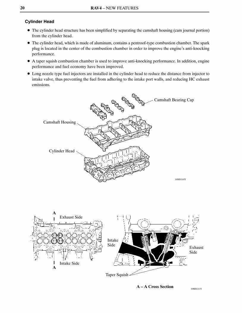
Camshaft Housing
Cylinder Head
Camshaft Bearing Cap
A
A
Exhaust Side
Intake Side
Intake Side
Taper Squish
Exhaust Side
A – A Cross Section
20
Cylinder Head
� The cylinder head structure has been simplified by separating the camshaft housing (cam journal portion)from the cylinder head.
� The cylinder head, which is made of aluminum, contains a pentroof-type combustion chamber. The sparkplug is located in the center of the combustion chamber in order to improve the engine’s anti-knockingperformance.
� A taper squish combustion chamber is used to improve anti-knocking performance. In addition, engineperformance and fuel economy have been improved.
� Long nozzle type fuel injectors are installed in the cylinder head to reduce the distance from injector tointake valve, thus preventing the fuel from adhering to the intake port walls, and reducing HC exhaustemissions.

RAV4 – NEW FEATURES
10SEG29Y
Crankshaft Bearing Cap
Plastic Region Tightening Bolt
Oil Drain Passage
A
A
Blowby Gas Passage
Oil Filter Bracket
Crankcase
Water Passage
Cylinder Block
Spiny-type Liner(Irregularly shaped outer casting surface of liner)
A – A Cross Section
21
Cylinder Block
� Water passages have been provided between the cylinder bores. By allowing the engine coolant to flowbetween the cylinder bores, this construction enables the temperature of the cylinder walls to be keptuniform.
� The liners are the spiny-type, which have been manufactured so that their casting exteriors form largeirregular surfaces in order to enhance the adhesion between the liners and the aluminum cylinder block.The enhanced adhesion helps heat dissipation, resulting in a lower overall temperature and heatdeformation of the cylinder bores.
� Blowby gas passages are provided in the crankcase.
� Oil drain passages are provided in the crankcase. This prevents the crankshaft from mixing the engineoil, which reduces rotational resistance.
� The oil filter bracket is integrated into the crankcase.
RAV4 – NEW FEATURES
10SEG30Y
Oil Separator
Separator Case
Oil Separator Cover
10SEG31Y
Bore Center
Crankshaft Center
Maximum Pressure
Crankshaft Center
Offset Crankshaft
Maximum Pressure
Center Crankshaft
Intake Side
Exhaust Side
22
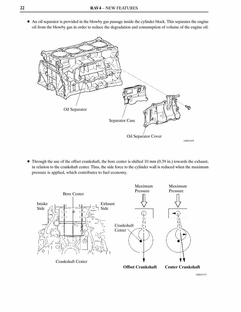
� An oil separator is provided in the blowby gas passage inside the cylinder block. This separates the engineoil from the blowby gas in order to reduce the degradation and consumption of volume of the engine oil.
� Through the use of the offset crankshaft, the bore center is shifted 10 mm (0.39 in.) towards the exhaust,in relation to the crankshaft center. Thus, the side force to the cylinder wall is reduced when the maximumpressure is applied, which contributes to fuel economy.
RAV4 – NEW FEATURES
10SEG32Y
A
A
Water Jacket Spacer
Water Jacket
Water Jacket Spacer
A – A Cross Section
23
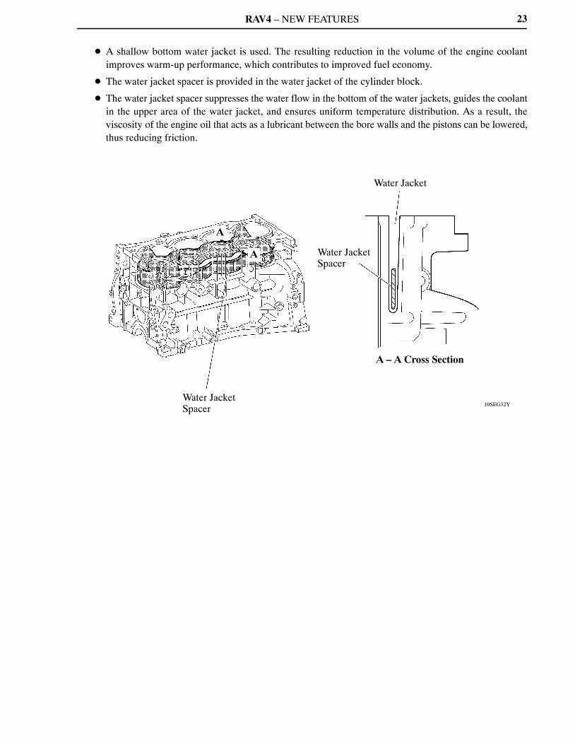
� A shallow bottom water jacket is used. The resulting reduction in the volume of the engine coolantimproves warm-up performance, which contributes to improved fuel economy.
� The water jacket spacer is provided in the water jacket of the cylinder block.
� The water jacket spacer suppresses the water flow in the bottom of the water jackets, guides the coolantin the upper area of the water jacket, and ensures uniform temperature distribution. As a result, theviscosity of the engine oil that acts as a lubricant between the bore walls and the pistons can be lowered,thus reducing friction.
RAV4 – NEW FEATURES
10SEG12Y
Anodic Oxide Coating
Resin Coating
Taper Squish ShapePiston Ring PVD Coating
No. 1 Compression Ring
No. 2 Compression Ring
Oil Ring
10SEG13Y
Plastic Region Tightening Bolt
Micro-grooved
24
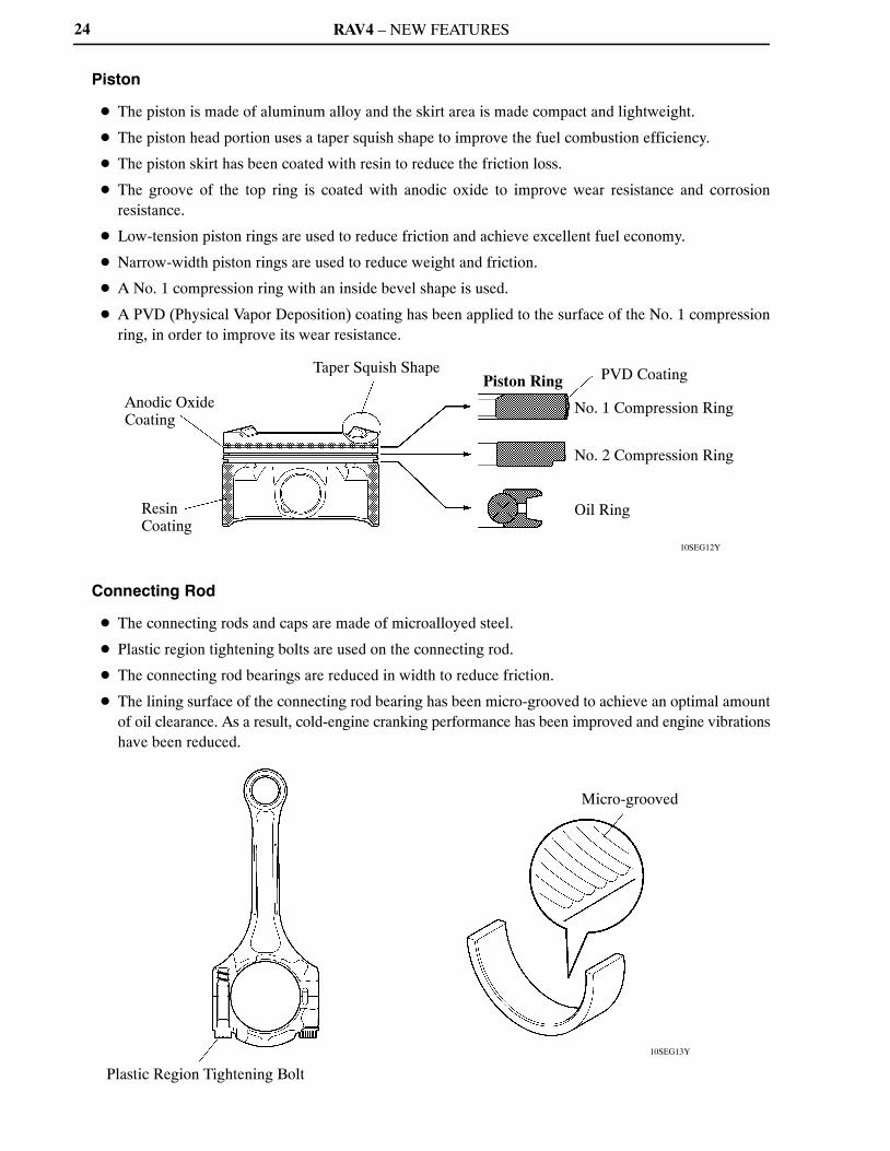
Piston
� The piston is made of aluminum alloy and the skirt area is made compact and lightweight.
� The piston head portion uses a taper squish shape to improve the fuel combustion efficiency.
� The piston skirt has been coated with resin to reduce the friction loss.
� The groove of the top ring is coated with anodic oxide to improve wear resistance and corrosionresistance.
� Low-tension piston rings are used to reduce friction and achieve excellent fuel economy.
� Narrow-width piston rings are used to reduce weight and friction.
� A No. 1 compression ring with an inside bevel shape is used.
� A PVD (Physical Vapor Deposition) coating has been applied to the surface of the No. 1 compressionring, in order to improve its wear resistance.
Connecting Rod
� The connecting rods and caps are made of microalloyed steel.
� Plastic region tightening bolts are used on the connecting rod.
� The connecting rod bearings are reduced in width to reduce friction.
� The lining surface of the connecting rod bearing has been micro-grooved to achieve an optimal amountof oil clearance. As a result, cold-engine cranking performance has been improved and engine vibrationshave been reduced.
RAV4 – NEW FEATURES
10SEG14Y
10SEG15Y
No. 1 Journal
Balance Weight
Balance Shaft Drive Gear
Crank PinOil Hole
Oil Groove Upper Main Bearing
Micro-grooved
Lower Main Bearing
25
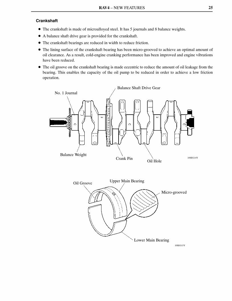
Crankshaft
� The crankshaft is made of microalloyed steel. It has 5 journals and 8 balance weights.
� A balance shaft drive gear is provided for the crankshaft.
� The crankshaft bearings are reduced in width to reduce friction.
� The lining surface of the crankshaft bearing has been micro-grooved to achieve an optimal amount ofoil clearance. As a result, cold-engine cranking performance has been improved and engine vibrationshave been reduced.
� The oil groove on the crankshaft bearing is made eccentric to reduce the amount of oil leakage from thebearing. This enables the capacity of the oil pump to be reduced in order to achieve a low frictionoperation.

RAV4 – NEW FEATURES
10SEG33Y
Balance Shaft Drive Gear
No. 2 Balance Shaft
Crankshaft
: Resin Gear
No. 2 Balance Shaft Housing
No. 1 Balance Shaft
No. 1 Balance Shaft Housing
26
Balance Shaft
1) General
� A balance shaft is used to reduce vibrations.
� The crankshaft directly drives the No. 1 balance shaft.
� In addition, a resin gear is used on the driven side to suppress noise and offer lightweight design.
RAV4 – NEW FEATURES
286EG71
Top Dead Center
Point of Max. Speed
Bottom Dead Center90�
Point of Max. Speed
Point of Max. Speed
286EG72
Inertial Force of Cylinders No. 2 and No. 3
Combined Inertial Force of All Cylinders(Unbalanced Secondary Inertial Force)
Inertial Force of Cylinder No. 1 and No. 4
–180�
–90�
Force
0�
90�
180�
270�
Inertial force that cannot be canceled
Crankshaft Angle
Inertial Force Generated by the In-line 4 Cylinders
10SEG71Y
0�
A
90�
CDB
180�
E
270�
Inertial Force of Balancer
Crankshaft Angle
Secondary Inertial Force
Mass Direction of Balance Shaft
Inertial Force of Balancer
Mass Direction of Balance Shaft at Crankshaft Angle
27
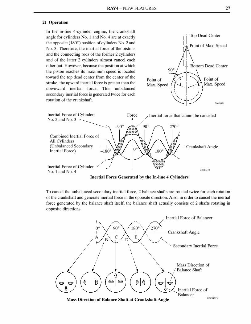
2) Operation
In the in-line 4-cylinder engine, the crankshaftangle for cylinders No. 1 and No. 4 are at exactlythe opposite (180�) position of cylinders No. 2 andNo. 3. Therefore, the inertial force of the pistonsand the connecting rods of the former 2 cylindersand of the latter 2 cylinders almost cancel eachother out. However, because the position at whichthe piston reaches its maximum speed is locatedtoward the top dead center from the center of thestroke, the upward inertial force is greater than thedownward inertial force. This unbalancedsecondary inertial force is generated twice for eachrotation of the crankshaft.
To cancel the unbalanced secondary inertial force, 2 balance shafts are rotated twice for each rotationof the crankshaft and generate inertial force in the opposite direction. Also, in order to cancel the inertialforce generated by the balance shaft itself, the balance shaft actually consists of 2 shafts rotating inopposite directions.
RAV4 – NEW FEATURES
10SEG16Y
Intake VVT-i Controller
Chain Slipper
Chain Tensioner
No. 2 Chain Damper
Exhaust VVT-i Controller
Intake Valve
Chain Damper
Exhaust Camshaft
Intake Camshaft
Exhaust Valve
Roller Rocker Arm
Hydraulic Lash Adjuster
Valve
28
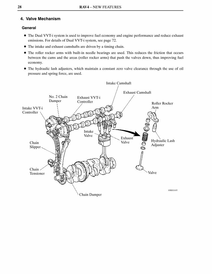
4. Valve Mechanism
General
� The Dual VVT-i system is used to improve fuel economy and engine performance and reduce exhaustemissions. For details of Dual VVT-i system, see page 72.
� The intake and exhaust camshafts are driven by a timing chain.
� The roller rocker arms with built-in needle bearings are used. This reduces the friction that occursbetween the cams and the areas (roller rocker arms) that push the valves down, thus improving fueleconomy.
� The hydraulic lash adjusters, which maintain a constant zero valve clearance through the use of oilpressure and spring force, are used.
RAV4 – NEW FEATURES
10SEG17Y
Intake VVT-i Controller
Exhaust VVT-i Controller
Timing Rotor
Timing Rotor
Indented R Portion of Cam (Profile)
Cam with Indented R
10SEG18Y
Chain Slipper
Chain Tensioner
No. 2 Chain Damper
Chain Damper
29
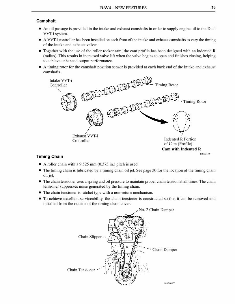
Camshaft
� An oil passage is provided in the intake and exhaust camshafts in order to supply engine oil to the DualVVT-i system.
� A VVT-i controller has been installed on each front of the intake and exhaust camshafts to vary the timingof the intake and exhaust valves.
� Together with the use of the roller rocker arm, the cam profile has been designed with an indented R(radius). This results in increased valve lift when the valve begins to open and finishes closing, helpingto achieve enhanced output performance.
� A timing rotor for the camshaft position sensor is provided at each back end of the intake and exhaustcamshafts.
Timing Chain
� A roller chain with a 9.525 mm (0.375 in.) pitch is used.
� The timing chain is lubricated by a timing chain oil jet. See page 30 for the location of the timing chainoil jet.
� The chain tensioner uses a spring and oil pressure to maintain proper chain tension at all times. The chaintensioner suppresses noise generated by the timing chain.
� The chain tensioner is ratchet type with a non-return mechanism.
� To achieve excellent serviceability, the chain tensioner is constructed so that it can be removed andinstalled from the outside of the timing chain cover.
RAV4 – NEW FEATURES
10SEG19Y
Roller Rocker Arm Cam
HydraulicLash Adjuster
OilPassage
Check Ball Spring
Check Ball
Plunger
OilPassage
Plunger Spring
Service Tip
Valve clearance adjustment is not necessary because a hydraulic lash adjuster is used.
10SEG34Y
Service Hole (for Intake VVT)
Service Hole (for Chain Tensioner)
Timing Chain Cover
A
Timing Chain Oil Jet
Oil Pump
View from A
30
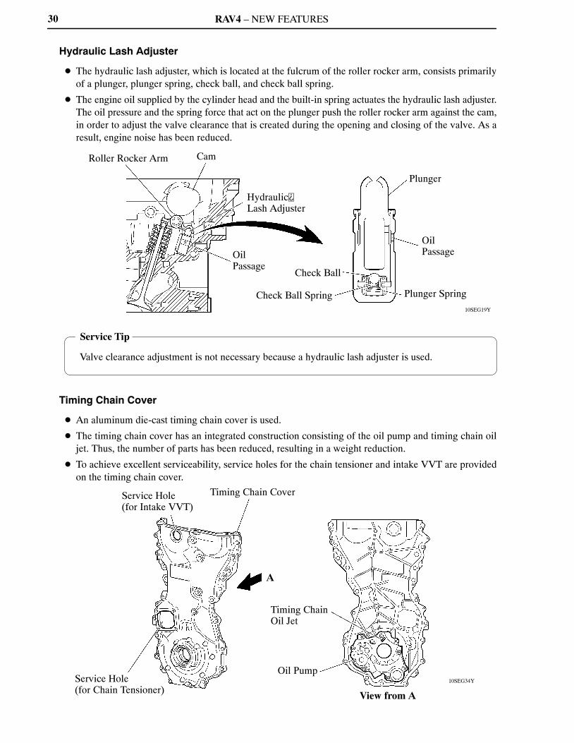
Hydraulic Lash Adjuster
� The hydraulic lash adjuster, which is located at the fulcrum of the roller rocker arm, consists primarilyof a plunger, plunger spring, check ball, and check ball spring.
� The engine oil supplied by the cylinder head and the built-in spring actuates the hydraulic lash adjuster.The oil pressure and the spring force that act on the plunger push the roller rocker arm against the cam,in order to adjust the valve clearance that is created during the opening and closing of the valve. As aresult, engine noise has been reduced.
Timing Chain Cover
� An aluminum die-cast timing chain cover is used.
� The timing chain cover has an integrated construction consisting of the oil pump and timing chain oiljet. Thus, the number of parts has been reduced, resulting in a weight reduction.
� To achieve excellent serviceability, service holes for the chain tensioner and intake VVT are providedon the timing chain cover.

RAV4 – NEW FEATURES
10SEG65Y
Intake Camshaft Timing Oil Control Valve
Intake VVT-i Controller
Exhaust VVT-i Controller
Chain Tensioner
Oil Pump
Oil Strainer
Exhaust Camshaft Timing Oil Control Valve
Piston Oil Jet
Balance Shaft
Oil Filter
Hydraulic LashAdjuster
31
5. Lubrication System
General
� The lubrication circuit is fully pressurized and oil passes through an oil filter.
� This engine has an oil return system in which the oil is force-fed to the upper cylinder head and returnsto the oil pan through the oil return hole in the cylinder head.
� A cycloid rotor type oil pump is used. The oil pump is directly driven by the crankshaft.
� The Dual VVT-i system is used. This system is operated by the engine oil.
RAV4 – NEW FEATURES
10SEG64I
Main Oil Hole
Bypass Valve
Relief Valve
Oil Filter
Oil Pump
Oil Strainer
TimingChain Oil Jet
TimingChain
Cylinder Head
Exhaust Camshaft Journals No. 2, 3, 4 and 5, andHydraulic Lash Adjusters
Intake OCV*
Intake VVT-i Controller
Oil DeliveryPipe
ExhaustOCV*
ExhaustVVT-iController
Piston Oil Jet
BalanceShaft
CrankshaftJournal No. 1
CrankshaftJournals No. 2 and 4
CrankshaftJournals No. 3 and 5
Chain Tensioner
CrankshaftPin
Oil Pan
*: OCV (Oil Control Valve)
Intake Camshaft Journals No. 1
Exhaust Camshaft Journals No. 1
Intake Camshaft Journals No. 2, 3, 4 and 5, andHydraulic Lash Adjusters
10SEG20Y
Oil Jet
Bottom Side View
Check Valve Oil
Oil Jet Cross Section
32
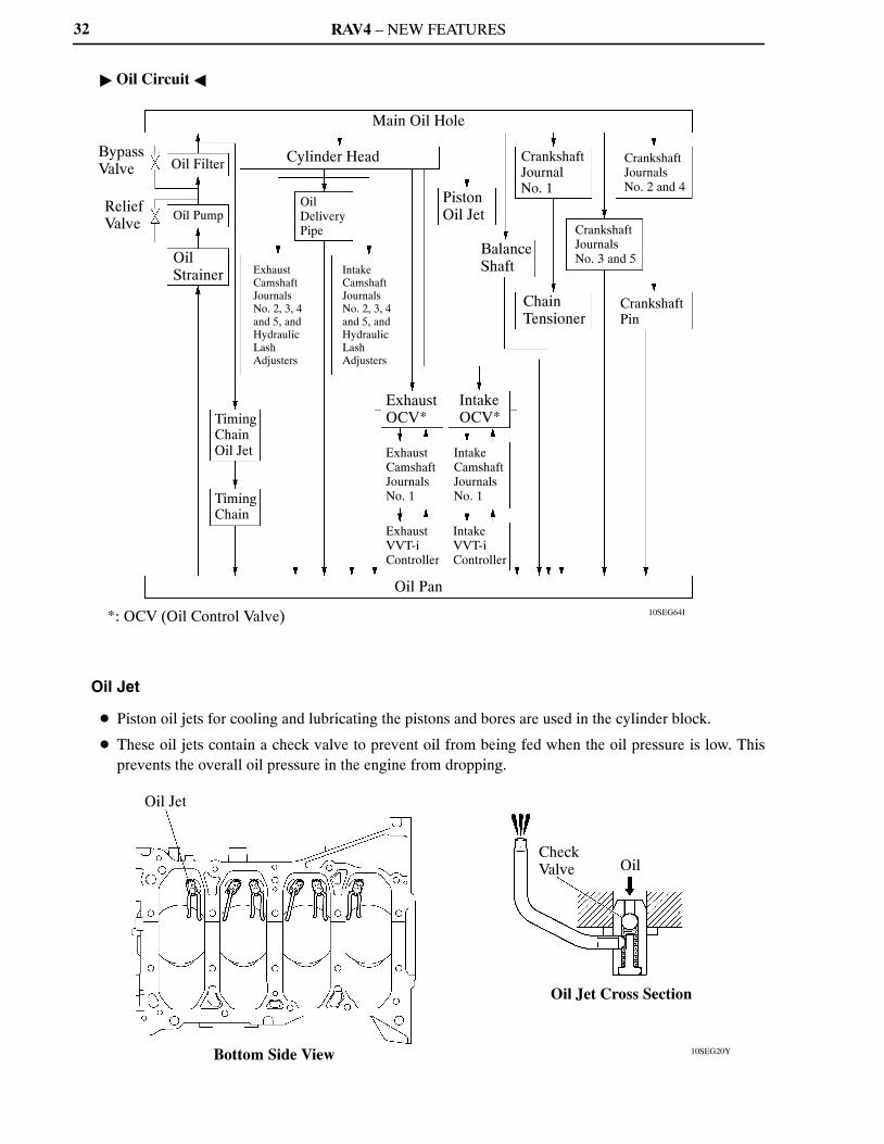
� Oil Circuit �
Oil Jet
� Piston oil jets for cooling and lubricating the pistons and bores are used in the cylinder block.
� These oil jets contain a check valve to prevent oil from being fed when the oil pressure is low. Thisprevents the overall oil pressure in the engine from dropping.
RAV4 – NEW FEATURES
10SEG63Y
Oil Filter Bracket
Element
Filter Cap
Drain Plug
Element
Filter Cap
Drain PlugDrain Pipe
Hose (Inside Diameter: 15 mm (0.59 in.))
When draining engine oil
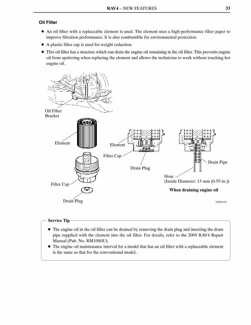
Service Tip
� The engine oil in the oil filter can be drained by removing the drain plug and inserting the drainpipe supplied with the element into the oil filter. For details, refer to the 2009 RAV4 RepairManual (Pub. No. RM10S0U).
� The engine oil maintenance interval for a model that has an oil filter with a replaceable elementis the same as that for the conventional model.
33
Oil Filter
� An oil filter with a replaceable element is used. The element uses a high-performance filter paper toimprove filtration performance. It is also combustible for environmental protection.
� A plastic filter cap is used for weight reduction.
� This oil filter has a structure which can drain the engine oil remaining in the oil filter. This prevents engineoil from spattering when replacing the element and allows the technician to work without touching hotengine oil.
RAV4 – NEW FEATURES
10SEG68Y
Reservoir Tank
Water Pump
Radiator
Thermostat
From Heater Core
To Heater Core
Throttle Body
ATF Warmer
10SEG35I
Bypass Passage
Water Pump
Thermostat
Cylinder Head
Cylinder Block
ReservoirTank
Radiator
Heater Core
ATFWarmer
ThrottleBody
34
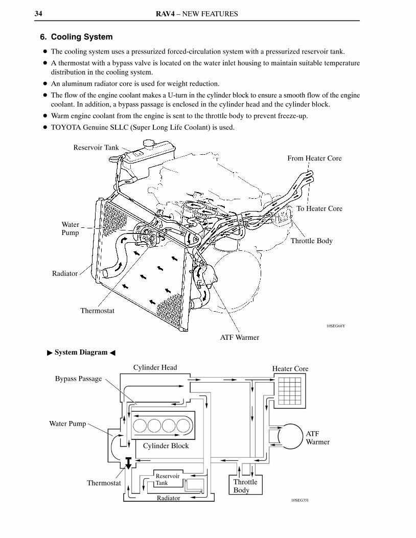
6. Cooling System
� The cooling system uses a pressurized forced-circulation system with a pressurized reservoir tank.
� A thermostat with a bypass valve is located on the water inlet housing to maintain suitable temperaturedistribution in the cooling system.
� An aluminum radiator core is used for weight reduction.
� The flow of the engine coolant makes a U-turn in the cylinder block to ensure a smooth flow of the enginecoolant. In addition, a bypass passage is enclosed in the cylinder head and the cylinder block.
� Warm engine coolant from the engine is sent to the throttle body to prevent freeze-up.
� TOYOTA Genuine SLLC (Super Long Life Coolant) is used.
� System Diagram �
RAV4 – NEW FEATURES 35
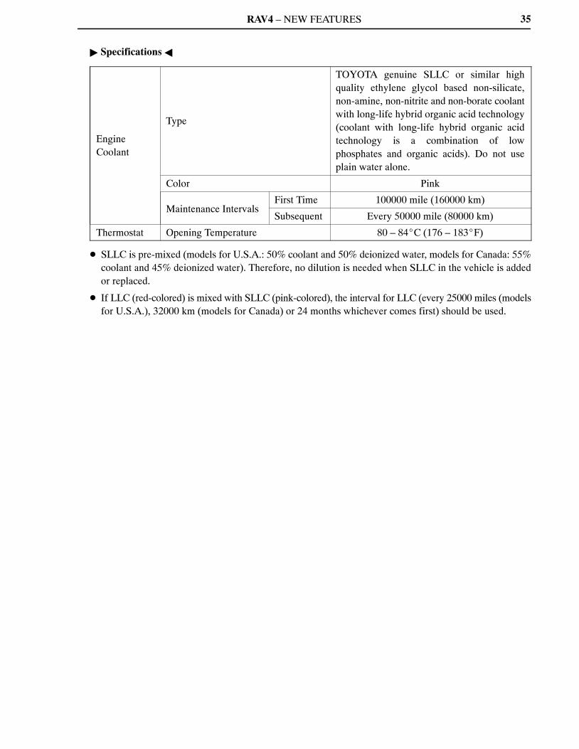
� Specifications �
EngineCoolant
Type
TOYOTA genuine SLLC or similar highquality ethylene glycol based non-silicate,non-amine, non-nitrite and non-borate coolantwith long-life hybrid organic acid technology(coolant with long-life hybrid organic acidtechnology is a combination of lowphosphates and organic acids). Do not useplain water alone.
Color Pink
Maintenance IntervalsFirst Time 100000 mile (160000 km)
Subsequent Every 50000 mile (80000 km)
Thermostat Opening Temperature 80 – 84�C (176 – 183�F)
� SLLC is pre-mixed (models for U.S.A.: 50% coolant and 50% deionized water, models for Canada: 55%coolant and 45% deionized water). Therefore, no dilution is needed when SLLC in the vehicle is addedor replaced.
� If LLC (red-colored) is mixed with SLLC (pink-colored), the interval for LLC (every 25000 miles (modelsfor U.S.A.), 32000 km (models for Canada) or 24 months whichever comes first) should be used.
RAV4 – NEW FEATURES
10SEG36Y
Exhaust Manifold
Intake Manifold
Air Cleaner
Exhaust Pipe
36
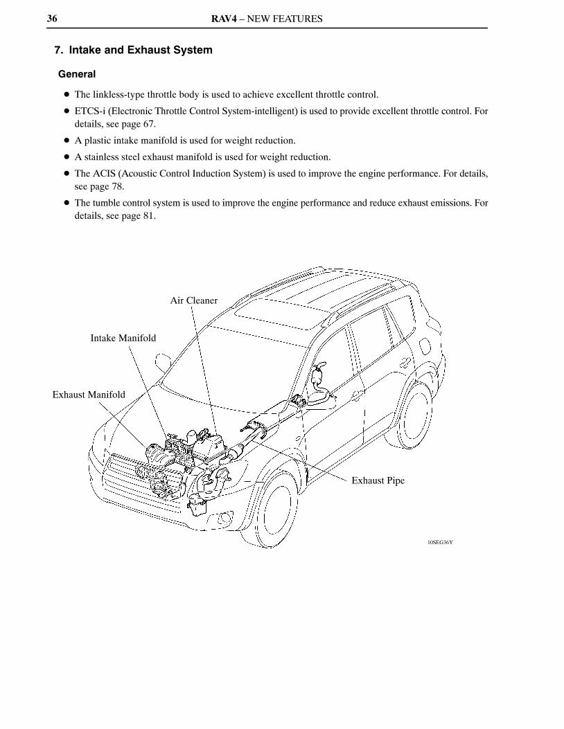
7. Intake and Exhaust System
General
� The linkless-type throttle body is used to achieve excellent throttle control.
� ETCS-i (Electronic Throttle Control System-intelligent) is used to provide excellent throttle control. Fordetails, see page 67.
� A plastic intake manifold is used for weight reduction.
� A stainless steel exhaust manifold is used for weight reduction.
� The ACIS (Acoustic Control Induction System) is used to improve the engine performance. For details,see page 78.
� The tumble control system is used to improve the engine performance and reduce exhaust emissions. Fordetails, see page 81.

RAV4 – NEW FEATURES
01MEG10Y
Air Cleaner Cap
Charcoal Filter
Air Cleaner Element (Nonwoven Fabric)
Service Tip
The charcoal filter, which is maintenance-free, cannot be removed from the air cleaner cap.
10SEG37Y
Throttle Position Sensor
Throttle Control Motor
37
Air Cleaner
� A nonwoven, full-fabric type air cleaner element is used.
� A charcoal filter, which absorbs the HC that accumulates in the intake system when the engine is stopped,is used in the air cleaner cap in order to reduce evaporative emissions.
Throttle Body
� The linkless-type throttle body is used and it achieves excellent throttle control.
� A DC motor with excellent response and minimal power consumption is used for the throttle controlmotor. The ECM performs the duty cycle control of the direction and the amperage of the current thatflows to the throttle control motor in order to regulate the opening angle of the throttle valve.
RAV4 – NEW FEATURES
10SEG40Y
10SEG39Y
10SEG38Y
Actuator (for Tumble Control System)
Tumble Control Valve
Mesh Type Gasket
VSV (for ACIS)
Intake Air Control Valve
Actuator (for ACIS)
Tumble Control Valve
Vacuum Tank
Intake Air Control Valve
Intake Manifold Cross Section
38
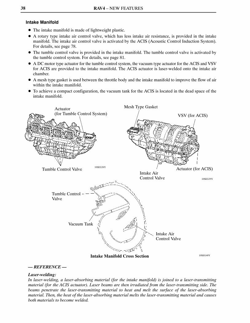
Intake Manifold
� The intake manifold is made of lightweight plastic.� A rotary type intake air control valve, which has less intake air resistance, is provided in the intake
manifold. The intake air control valve is activated by the ACIS (Acoustic Control Induction System).For details, see page 78.
� The tumble control valve is provided in the intake manifold. The tumble control valve is activated bythe tumble control system. For details, see page 81.
� A DC motor type actuator for the tumble control system, the vacuum type actuator for the ACIS and VSVfor ACIS are provided to the intake manifold. The ACIS actuator is laser-welded onto the intake airchamber.
� A mesh type gasket is used between the throttle body and the intake manifold to improve the flow of airwithin the intake manifold.
� To achieve a compact configuration, the vacuum tank for the ACIS is located in the dead space of theintake manifold.
— REFERENCE —
Laser-welding:In laser-welding, a laser-absorbing material (for the intake manifold) is joined to a laser-transmittingmaterial (for the ACIS actuator). Laser beams are then irradiated from the laser-transmitting side. Thebeams penetrate the laser-transmitting material to heat and melt the surface of the laser-absorbingmaterial. Then, the heat of the laser-absorbing material melts the laser-transmitting material and causesboth materials to become welded.

RAV4 – NEW FEATURES
10SEG21Y
TWC
10SEG41Y
Ball JointSpring
Bolt
Gasket
Ball Joint
TWC
Main Muffler
Ball Joint
Sub Muffler
39
Exhaust Manifold
A stainless steel exhaust manifold is used for improving the warm-up of the TWC (Three-Way Catalyticconverter) and for weight reduction.
Exhaust Pipe
� The exhaust pipe uses two ball joints in order to achieve a simple construction and ensured reliability.
� The TWC is used to reduce exhaust emissions.
RAV4 – NEW FEATURES
10SEG42Y
Injector
Bottom Side View
Pulsation Damper
Quick Connector
Fuel Delivery PipeInjector
Canister
Fuel Tank
Fuel Pump Assembly� Fuel Filter� Pressure Regulator
40
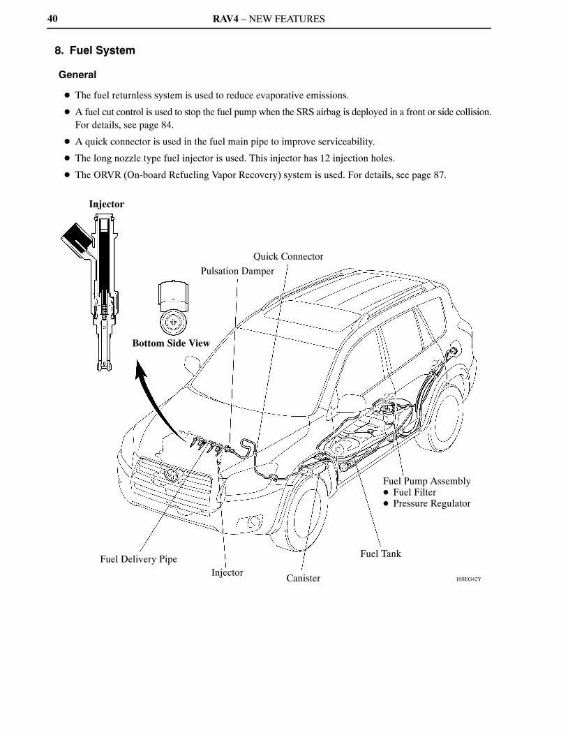
8. Fuel System
General
� The fuel returnless system is used to reduce evaporative emissions.
� A fuel cut control is used to stop the fuel pump when the SRS airbag is deployed in a front or side collision.For details, see page 84.
� A quick connector is used in the fuel main pipe to improve serviceability.
� The long nozzle type fuel injector is used. This injector has 12 injection holes.
� The ORVR (On-board Refueling Vapor Recovery) system is used. For details, see page 87.

RAV4 – NEW FEATURES
185EG16
Pulsation Damper
Fuel Filter
Fuel Pump
Pressure Regulator
Fuel Tank
Fuel Pump Assembly
41
Fuel Returnless System
The fuel returnless system is used to reduce the evaporative emission. As shown below, by integrating thefuel filter and pressure regulator with the fuel pump assembly, the fuel return system in which the fuelreturns from the engine area has been discontinued and temperature rise inside the fuel tank is prevented.
RAV4 – NEW FEATURES
165EG25
CamshaftPositionSensor
CrankshaftPositionSensor
VariousSensors
G2
NEECM
IGT1
IGT2
IGT3
IGT4
IGF
+B
Ignition Coil (with Igniter)
No. 1 Cylinder
No. 2 Cylinder
No. 3 Cylinder
No. 4 Cylinder
42
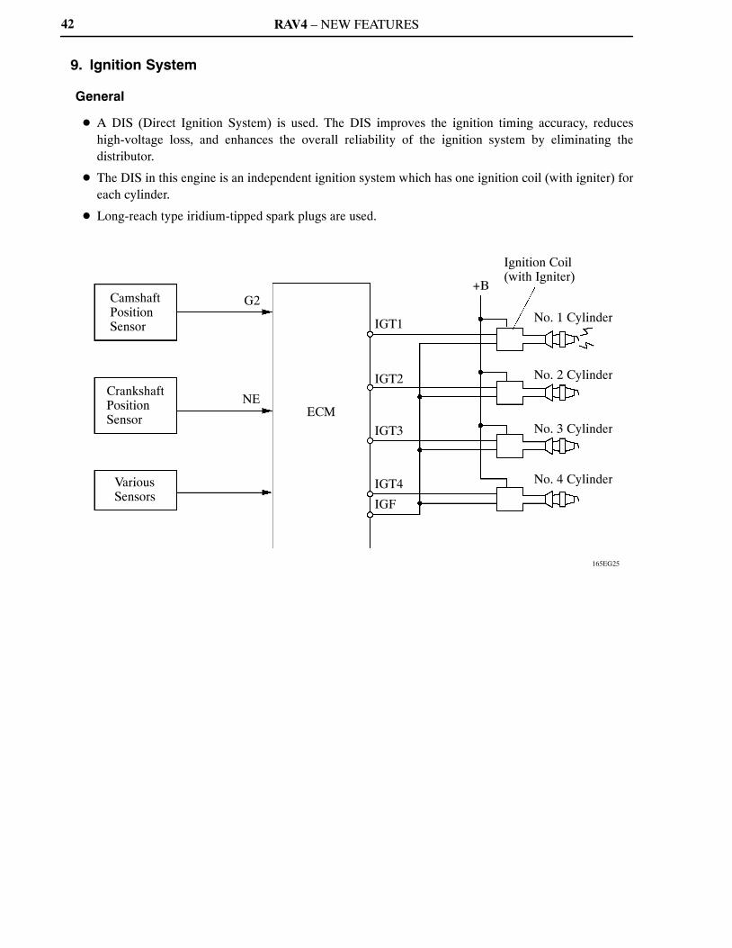
9. Ignition System
General
� A DIS (Direct Ignition System) is used. The DIS improves the ignition timing accuracy, reduceshigh-voltage loss, and enhances the overall reliability of the ignition system by eliminating thedistributor.
� The DIS in this engine is an independent ignition system which has one ignition coil (with igniter) foreach cylinder.
� Long-reach type iridium-tipped spark plugs are used.
RAV4 – NEW FEATURES
208EG70
04FEG60Y
Long-reach Type Conventional Type
Iridium Tip
Platinum Tip
43
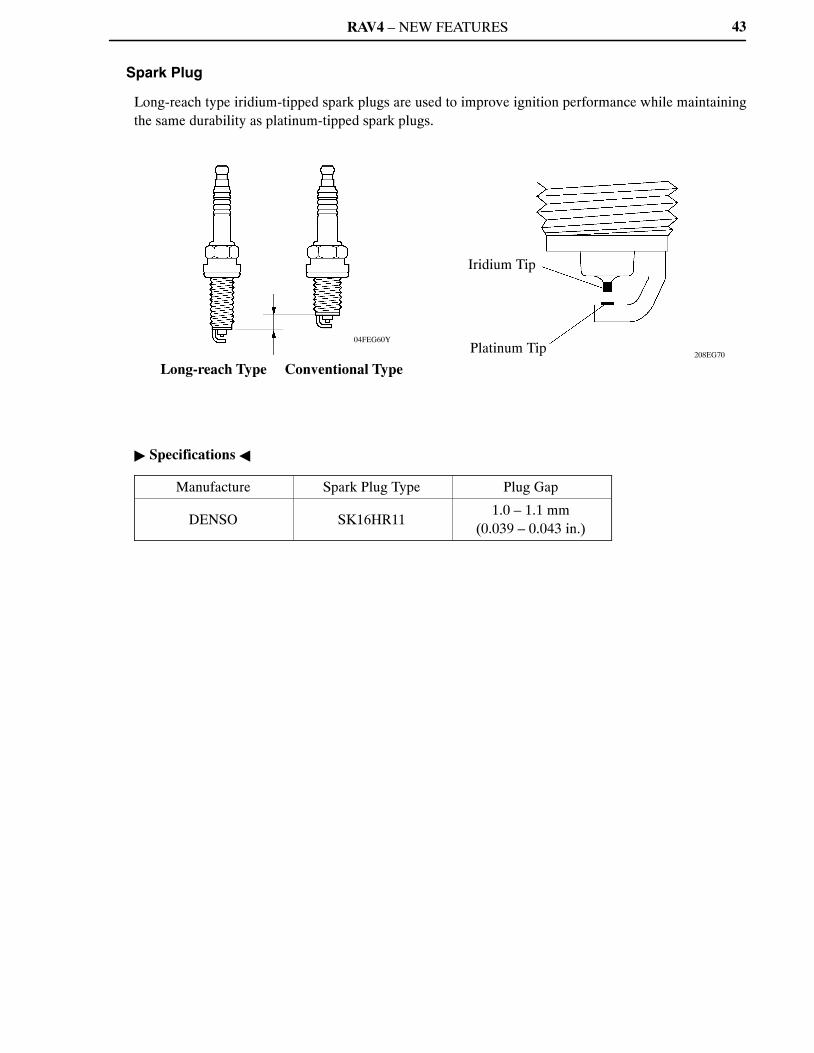
Spark Plug
Long-reach type iridium-tipped spark plugs are used to improve ignition performance while maintainingthe same durability as platinum-tipped spark plugs.
� Specifications �
Manufacture Spark Plug Type Plug Gap
DENSO SK16HR111.0 – 1.1 mm
(0.039 – 0.043 in.)

RAV4 – NEW FEATURES
206EG41206EG40
206EG42
Stator
A
A
Segment Conductor Stator
Joined Segment Conductor System
SegmentConductor
Joined A – A CrossSection
Stator
B
B
Stator Conductor Wire
Wiring System
Conductor Wire
B – B Cross Section
Segment Conductor Type Generator
Stator
Conventional Type Generator
Segment Conductor
Cross Section
Stator of Segment Conductor Type Generator
44
10. Charging System
General
A compact and lightweight segment conductor type generator is used.
� Specifications �
Type SE0
Rated Voltage 12 V
Rated Output 100 A
Segment Conductor Type Generator
� The segment conductor type generator generates a high amperage output in a highly efficient manner.
� This generator uses a joined segment conductor system, in which multiple segment conductors arewelded together to the stator. Compared to the conventional winding system, the electrical resistance hasbeen reduced due to the shape of the segment conductors, and their arrangement helps to make thegenerator more compact.

RAV4 – NEW FEATURES
008EG08Y
Generator
E
Regulator
B
M
IG
S
L
Ignition Switch
Discharge Warning Light
45
� Wiring Diagram �

RAV4 – NEW FEATURES
01NEG46Y
Surface Commutator
Armature
Length
Brush
Permanent Magnet
46
11. Starting System
General
� A compact and lightweight PS (Planetary reduction-Segment conductor motor) type starter is used.
� Because the PS type starter contains an armature that uses square-shaped conductors, and its surfacefunctions as a commutator, its output torque has been improved and its overall length has been reduced.
� In place of the field coil used in the conventional type starter, the PS type starter uses two types ofpermanent magnets: main magnets and interpolar magnets. The main magnets and interpolar magnetshave been efficiently arranged to increase the magnetic flux and to shorten the length of the yoke.
� Specifications �
Starter Type PS Type
Rating Output 1.7 kW
Rating Voltage 12 V
Length*1 128.1 mm (5.04 in.)
Weight 2930 g (6.46 lb)
Rotational Direction*2 Counterclockwise
*1: Length from the mounted area to the rear end of the starter*2: Viewed from pinion side
RAV4 – NEW FEATURES
206EG20
Conventional Type
Armature
PS Type
Brush
Commutator
Brush
Surface Commutator
Square-shaped Conductor
A – A Cross Section
(PS Type)
Round-shaped Conductor
B – B Cross Section
(Conventional Type)
Armature
B
A
B
A
222EG15
Main Magnet
Yoke
Interpolar Magnet
Main Magnet
Armature
Cross Section of Yoke
Magnetic Flux Generated by Relationship between Main Magnets
Magnetic Flux Generated by Interpolar Magnets
NSN
NSS
47
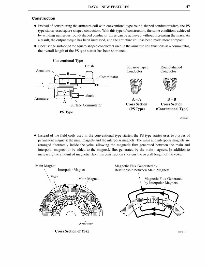
Construction
� Instead of constructing the armature coil with conventional type round-shaped conductor wires, the PStype starter uses square-shaped conductors. With this type of construction, the same conditions achievedby winding numerous round-shaped conductor wires can be achieved without increasing the mass. Asa result, the output torque has been increased, and the armature coil has been made more compact.
� Because the surface of the square-shaped conductors used in the armature coil functions as a commutator,the overall length of the PS type starter has been shortened.
� Instead of the field coils used in the conventional type starter, the PS type starter uses two types ofpermanent magnets: the main magnets and the interpolar magnets. The main and interpolar magnets arearranged alternately inside the yoke, allowing the magnetic flux generated between the main andinterpolar magnets to be added to the magnetic flux generated by the main magnets. In addition toincreasing the amount of magnetic flux, this construction shortens the overall length of the yoke.

RAV4 – NEW FEATURES
10SEG22Y
Idler Pulley for Automatic Tensioner
Crankshaft Pulley
Air Conditioning Compressor Pulley
Water Pump Pulley
Generator Pulley
10SEG23Y
Spring
Arm
Idler Pulley
Cross Section
Fulcrum
Arm
Belt Loosen Direction
Belt Tension Direction
Idler Pulley
48
12. Serpentine Belt Drive System
General
� Accessory components are driven by a serpentine belt consisting of a single V-ribbed belt. It reduces theoverall engine length, weight and the number of engine parts.
� An automatic tensioner eliminates the need for tension adjustment.
Automatic Tensioner
The tension of the V-ribbed belt is properly maintained by the tension spring enclosed in the automatictensioner.
RAV4 – NEW FEATURES 49
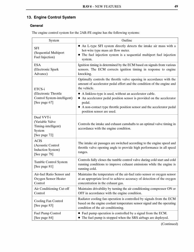
13. Engine Control System
General
The engine control system for the 2AR-FE engine has the following systems:
System Outline
SFI(Sequential MultiportFuel Injection)
� An L-type SFI system directly detects the intake air mass with ahot-wire type mass air flow meter.
� The fuel injection system is a sequential multiport fuel injectionsystem.
ESA(Electronic SparkAdvance)
Ignition timing is determined by the ECM based on signals from varioussensors. The ECM corrects ignition timing in response to engineknocking.
ETCS-i(Electronic ThrottleControl System-intelligent)[See page 67]
Optimally controls the throttle valve opening in accordance with theamount of accelerator pedal effort and the condition of the engine andthe vehicle.
� A linkless-type is used, without an accelerator cable.� An accelerator pedal position sensor is provided on the accelerator
pedal.� A non-contact type throttle position sensor and the accelerator pedal
position sensor are used.
Dual VVT-i(Variable ValveTiming-intelligent)System[See page 72]
Controls the intake and exhaust camshafts to an optimal valve timing inaccordance with the engine condition.
ACIS(Acoustic ControlInduction System)[See page 78]
The intake air passages are switched according to the engine speed andthrottle valve opening angle to provide high performance in all speedranges.
Tumble Control System[See page 81]
Controls fully closes the tumble control valve during cold start and coldrunning conditions to improve exhaust emissions while the engine isrunning cold.
Air-fuel Ratio Sensor andOxygen Sensor HeaterControl
Maintains the temperature of the air-fuel ratio sensor or oxygen sensorat an appropriate level to achieve accuracy of detection of the oxygenconcentration in the exhaust gas.
Air Conditioning Cut-offControl
Maintains drivability by turning the air conditioning compressor ON orOFF in accordance with the engine condition.
Cooling Fan Control[See page 83]
Radiator cooling fan operation is controlled by signals from the ECMbased on the engine coolant temperature sensor signal and the operatingcondition of the air conditioning.
Fuel Pump Control[See page 84]
� Fuel pump operation is controlled by a signal from the ECM.� The fuel pump is stopped when the SRS airbags are deployed.
(Continued)
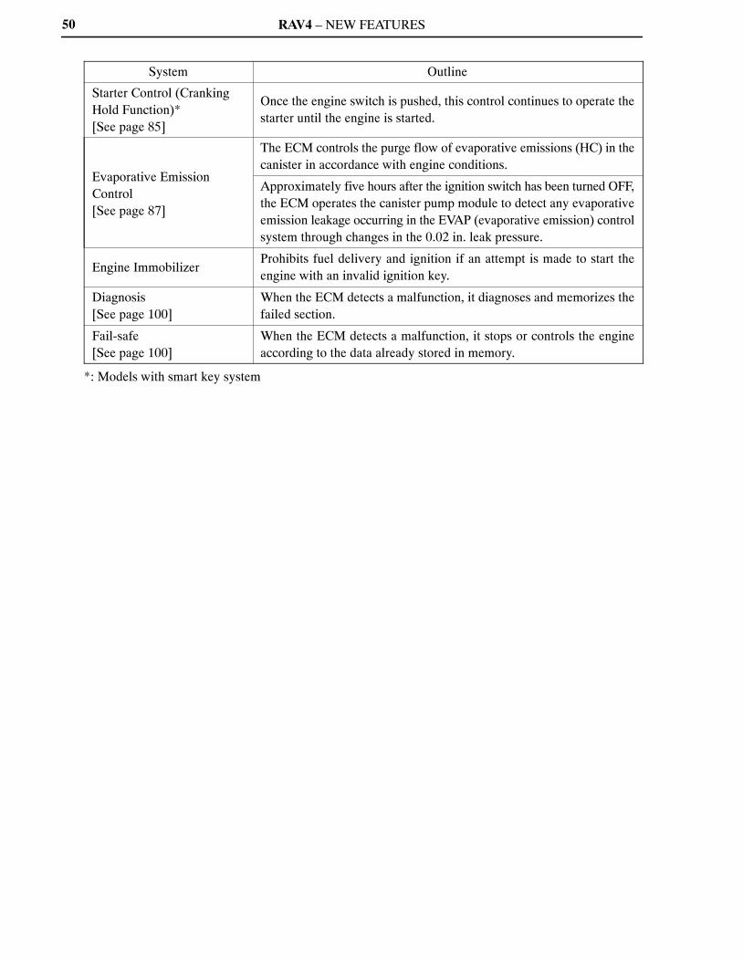
RAV4 – NEW FEATURES50
System Outline
Starter Control (CrankingHold Function)*[See page 85]
Once the engine switch is pushed, this control continues to operate thestarter until the engine is started.
Evaporative EmissionControl[See page 87]
The ECM controls the purge flow of evaporative emissions (HC) in thecanister in accordance with engine conditions.
Approximately five hours after the ignition switch has been turned OFF,the ECM operates the canister pump module to detect any evaporativeemission leakage occurring in the EVAP (evaporative emission) controlsystem through changes in the 0.02 in. leak pressure.
Engine ImmobilizerProhibits fuel delivery and ignition if an attempt is made to start theengine with an invalid ignition key.
Diagnosis[See page 100]
When the ECM detects a malfunction, it diagnoses and memorizes thefailed section.
Fail-safe[See page 100]
When the ECM detects a malfunction, it stops or controls the engineaccording to the data already stored in memory.
*: Models with smart key system

RAV4 – NEW FEATURES
10SEG05Y
MASS AIR FLOW METER
INTAKE AIR TEMPERATURE SENSOR
ENGINE COOLANT TEMPERATURE SENSOR
THROTTLE POSITION SENSOR
CRANKSHAFT POSITION SENSOR
INTAKE CAMSHAFT POSITION SENSOR
EXHAUST CAMSHAFT POSITION SENSOR
ACCELERATOR PEDAL POSITION SENSOR
AIR-FUEL RATIO SENSOR(Bank 1, Sensor 1)
HEATED OXYGEN SENSOR(Bank 1, Sensor 2)
KNOCK SENSOR
TUMBLE CONTROLVALVE POSITION SENSOR
CANISTER PUMP MODULE
CANISTER PRESSURESENSOR
IGNITION SWITCH*
ECM
VG
THA
THW
VTA1
VTA2
NE
G2
EV1
VPA
VPA2
A1A
OX1B
KNK1
IAC1
PPMP
IGSW
STA
#10
#20
#30
#40
IGT1 –IGT4
IGF1
M
OC1
OE1
ACIS
FC
SFI
No. 1 INJECTOR
No. 2 INJECTOR
No. 3 INJECTOR
No. 4 INJECTOR
ESA
IGNITION COIL with IGNITER
SPARK PLUG
ETCS-i
THROTTLE CONTROL MOTOR
DUAL VVT-i
INTAKE CAMSHAFT TIMING OIL CONTROL VALVE
EXHAUST CAMSHAFT TIMING OIL CONTROL VALVE
ACIS
VSV
FUEL PUMP CONTROL
CIRCUIT OPENING RELAY
FUEL PUMP
51
Construction
The configuration of the engine control system in the 2AR-FE engine is shown in the following chart:
(Continued)
*: Except models with smart key system

RAV4 – NEW FEATURES
10SEG06Y
IG2 RELAY*
MAIN BODY ECU*
ENGINE SWITCH*
PARK/NEUTRAL POSITION SWITCH
TRANSMISSION CONTROL SWITCH
CRUISE CONTROL SWITCH
GENERATOR
DEFOGGER SWITCH
TAILLIGHT SWITCH
STOP LIGHT SWITCH
TRANSPONDER KEY ECU
BATTERY
IGSW
NSW
R, P, N
D, 2, L
3
CCS
ALT
ELS1
ELS3
STP
ST1–
IMI
IMO
BATT
ECM
HA1A
HT1B
IA1
FANH
FANL
STSW
ACCR
STAR
STA
AIR-FUEL RATIO AND HEATED OXYGEN SENSORHEATER CONTROL
AIR-FUEL RATIO SENSORHEATER (Bank 1, Sensor 1)
HEATED OXYGEN SENSORHEATER (Bank 1, Sensor 2)
TUMBLE CONTROL SYSTEM
ACTUATOR (DC MOTOR)
COOLING FAN CONTROL
No. 1 COOLING FAN RELAY
No. 2 COOLING FAN RELAY
No. 3 COOLING FAN RELAY
STARTER CONTROL*
MAIN BODY ECU
IG2 RELAY
STARTER CUT RELAY
STARTER RELAY
52
(Continued)
*: Models with smart key system
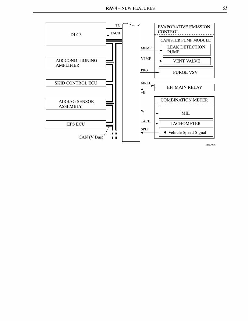
RAV4 – NEW FEATURES
10SEG07Y
DLC3
AIR CONDITIONING AMPLIFIER
SKID CONTROL ECU
AIRBAG SENSOR ASSEMBLY
EPS ECU
CAN (V Bus)
TC
TACH
MPMP
VPMP
PRG
MREL
+B
W
TACH
SPD
EVAPORATIVE EMISSIONCONTROL
CANISTER PUMP MODULE
LEAK DETECTION PUMP
VENT VALVE
PURGE VSV
EFI MAIN RELAY
COMBINATION METER
MIL
TACHOMETER
� Vehicle Speed Signal
53

RAV4 – NEW FEATURES
10SEG55Y
Cruise Control Switch
No. 1 Cooling Fan RelayNo. 2 Cooling Fan RelayNo. 3 Cooling Fan Relay
Accelerator Pedal Position Sensor
EFI Main Relay
DLC3
Various ECUs
Starter Cut Relay*1
Engine Switch*1
Starter Relay*1
Main Body ECU*1
IG2 Relay*1
MIL
Ignition Switch*2
Park/NeutralPosition Switch
Battery
ECM
Exhaust CamshaftPositionSensor
IgnitionCoil withIgniter
IntakeCamshaftPositionSensor
VSV (for ACIS)
Transponder Key ECU
PurgeVSV
Mass Air Flow Meter*5
*3 *4
Injector
Tumble Control Valve Position Sensor
Actuator (for Tumble Control System)
Knock Sensor
Engine Coolant TemperatureSensor
Crankshaft Position Sensor
Throttle ControlMotor
Throttle Position Sensor
Circuit Opening Relay
Canister Filter
Fuel PumpTWC TWC
Air-fuel Ratio Sensor(Bank 1, Sensor 1)
Heated Oxygen Sensor(Bank 1, Sensor 2)
Canister Pump Module� Vent Valve� Leak Detection Pump� Canister Pressure Sensor
54
Engine Control System Diagram
*1: Models with smart key system*2: Except models with smart key system*3: Exhaust Camshaft Timing Oil Control Valve*4: Intake Camshaft Timing Oil Control Valve*5: Built-in intake air temperature sensor
RAV4 – NEW FEATURES
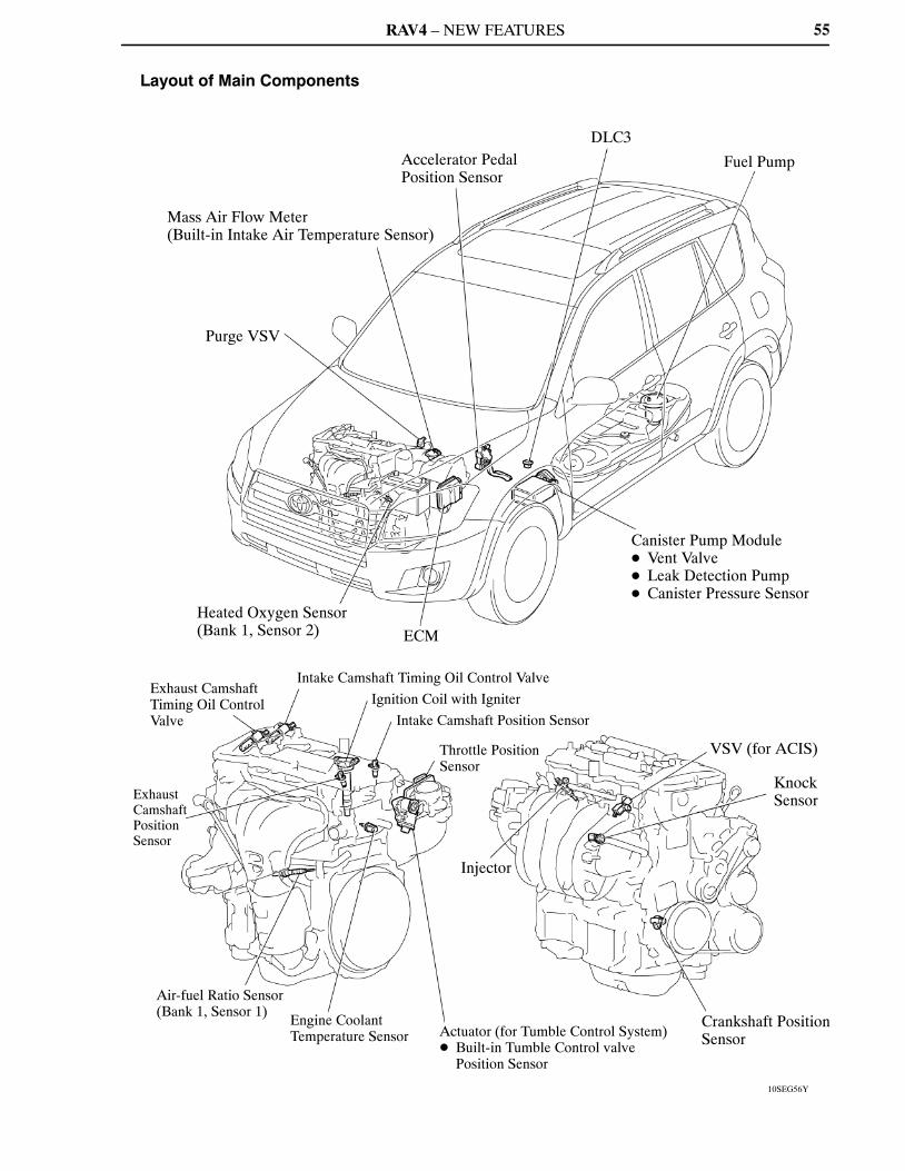
10SEG56Y
Accelerator Pedal Position Sensor
Mass Air Flow Meter(Built-in Intake Air Temperature Sensor)
Purge VSV
Heated Oxygen Sensor(Bank 1, Sensor 2) ECM
Canister Pump Module� Vent Valve� Leak Detection Pump� Canister Pressure Sensor
Fuel Pump
DLC3
Intake Camshaft Timing Oil Control ValveExhaust Camshaft Timing Oil Control Valve
Exhaust Camshaft Position Sensor
Air-fuel Ratio Sensor(Bank 1, Sensor 1)
Engine Coolant Temperature Sensor Actuator (for Tumble Control System)
� Built-in Tumble Control valve Position Sensor
Throttle Position Sensor
Intake Camshaft Position Sensor
Ignition Coil with Igniter
Injector
Crankshaft Position Sensor
Knock Sensor
VSV (for ACIS)
55
Layout of Main Components
RAV4 – NEW FEATURES56
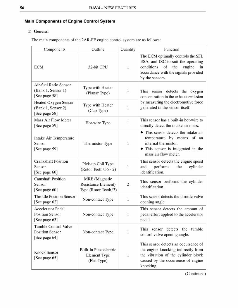
Main Components of Engine Control System
1) General
The main components of the 2AR-FE engine control system are as follows:
Components Outline Quantity Function
ECM 32-bit CPU 1
The ECM optimally controls the SFI,ESA, and ISC to suit the operatingconditions of the engine inaccordance with the signals providedby the sensors.
Air-fuel Ratio Sensor(Bank 1, Sensor 1)[See page 58]
Type with Heater(Planar Type)
1 This sensor detects the oxygenconcentration in the exhaust emissionby measuring the electromotive forcegenerated in the sensor itself.
Heated Oxygen Sensor(Bank 1, Sensor 2)[See page 58]
Type with Heater(Cup Type)
1
Mass Air Flow Meter[See page 59]
Hot-wire Type 1This sensor has a built-in hot-wire todirectly detect the intake air mass.
Intake Air TemperatureSensor[See page 59]
Thermistor Type 1
� This sensor detects the intake airtemperature by means of aninternal thermistor.
� This sensor is integrated in themass air flow meter.
Crankshaft PositionSensor[See page 60]
Pick-up Coil Type(Rotor Teeth/36 - 2)
1This sensor detects the engine speedand performs the cylinderidentification.
Camshaft PositionSensor[See page 60]
MRE (MagneticResistance Element)Type (Rotor Teeth/3)
2This sensor performs the cylinderidentification.
Throttle Position Sensor[See page 62]
Non-contact Type 1This sensor detects the throttle valveopening angle.
Accelerator PedalPosition Sensor[See page 63]
Non-contact Type 1This sensor detects the amount ofpedal effort applied to the acceleratorpedal.
Tumble Control ValvePosition Sensor[See page 64]
Non-contact Type 1This sensor detects the tumblecontrol valve opening angle.
Knock Sensor[See page 65]
Built-in PiezoelectricElement Type
(Flat Type)1
This sensor detects an occurrence ofthe engine knocking indirectly fromthe vibration of the cylinder blockcaused by the occurrence of engineknocking.
(Continued)
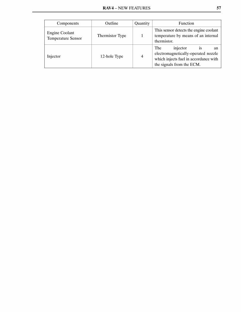
RAV4 – NEW FEATURES 57
Components Outline Quantity Function
Engine CoolantTemperature Sensor
Thermistor Type 1This sensor detects the engine coolanttemperature by means of an internalthermistor.
Injector 12-hole Type 4
The injector is anelectromagnetically-operated nozzlewhich injects fuel in accordance withthe signals from the ECM.
RAV4 – NEW FEATURES
00REG21Y
D13N11
Air-fuel Ratio Sensor
A1A+(3.3 V)
A1A–(2.9 V)
ECM
Air-fuel Ratio Sensor Circuit
Heated Oxygen Sensor
OX1B
EX1B
ECM
Heated Oxygen Sensor
: Air-fuel Ratio Sensor: Heated Oxygen Sensor
4.2
Air-fuel Ratio Sensor Data Displayed on Techstream
2.2
11 (Rich) 14.7 19 (Lean)
Air-fuel Ratio
1
Heated Oxygen Sensor Output (V)
0.1
58
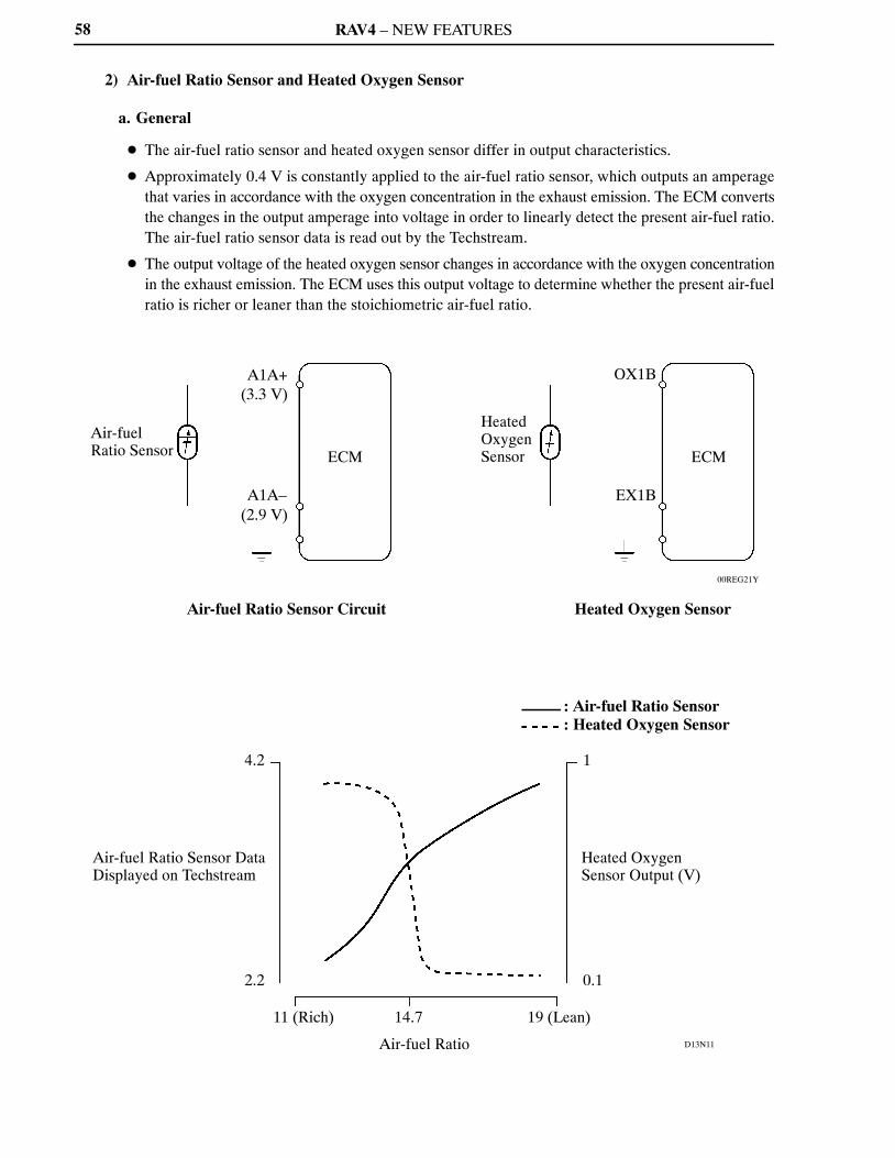
2) Air-fuel Ratio Sensor and Heated Oxygen Sensor
a. General
� The air-fuel ratio sensor and heated oxygen sensor differ in output characteristics.
� Approximately 0.4 V is constantly applied to the air-fuel ratio sensor, which outputs an amperagethat varies in accordance with the oxygen concentration in the exhaust emission. The ECM convertsthe changes in the output amperage into voltage in order to linearly detect the present air-fuel ratio.The air-fuel ratio sensor data is read out by the Techstream.
� The output voltage of the heated oxygen sensor changes in accordance with the oxygen concentrationin the exhaust emission. The ECM uses this output voltage to determine whether the present air-fuelratio is richer or leaner than the stoichiometric air-fuel ratio.
RAV4 – NEW FEATURES
10SEG50Y
Alumina
Dilation Layer
Alumina
Platinum Electrode
Sensor Element (Zirconia)
Heater
Atmosphere
Planar Type Air-fuel Ratio Sensor
Heater
Platinum Electrode
Sensor Element (Zirconia)
Atmosphere
Cup Type Heated Oxygen Sensor
01YEG10Y
Hot-wire Element
Temperature Sensing Element
Air FlowIntake Air Temperature Sensor
59
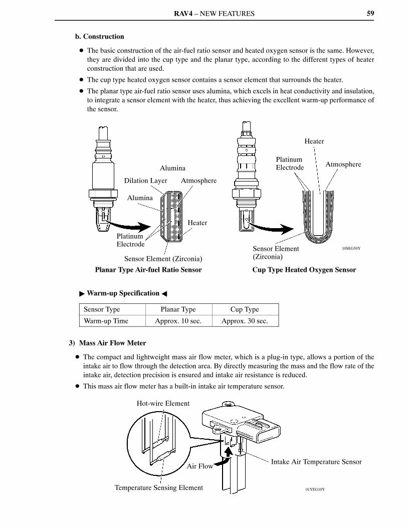
b. Construction
� The basic construction of the air-fuel ratio sensor and heated oxygen sensor is the same. However,they are divided into the cup type and the planar type, according to the different types of heaterconstruction that are used.
� The cup type heated oxygen sensor contains a sensor element that surrounds the heater.
� The planar type air-fuel ratio sensor uses alumina, which excels in heat conductivity and insulation,to integrate a sensor element with the heater, thus achieving the excellent warm-up performance ofthe sensor.
� Warm-up Specification �
Sensor Type Planar Type Cup Type
Warm-up Time Approx. 10 sec. Approx. 30 sec.
3) Mass Air Flow Meter
� The compact and lightweight mass air flow meter, which is a plug-in type, allows a portion of theintake air to flow through the detection area. By directly measuring the mass and the flow rate of theintake air, detection precision is ensured and intake air resistance is reduced.
� This mass air flow meter has a built-in intake air temperature sensor.
RAV4 – NEW FEATURES
10SEG60Y10SEG59Y
Crankshaft Position Sensor
Exhaust Camshaft Position Sensor
Timing Rotor Timing Rotor
Intake Camshaft Position Sensor
Timing Rotor
10SEG57I
10SEG58I
720� CA
180� CA 180� CA 180� CA 180� CA
5 V
0 V
Camshaft Position Sensor Output Waveform
720� CA
360� CA 360� CA
0 V
2 Teeth Missing
Crankshaft Position Sensor Output Waveform
60
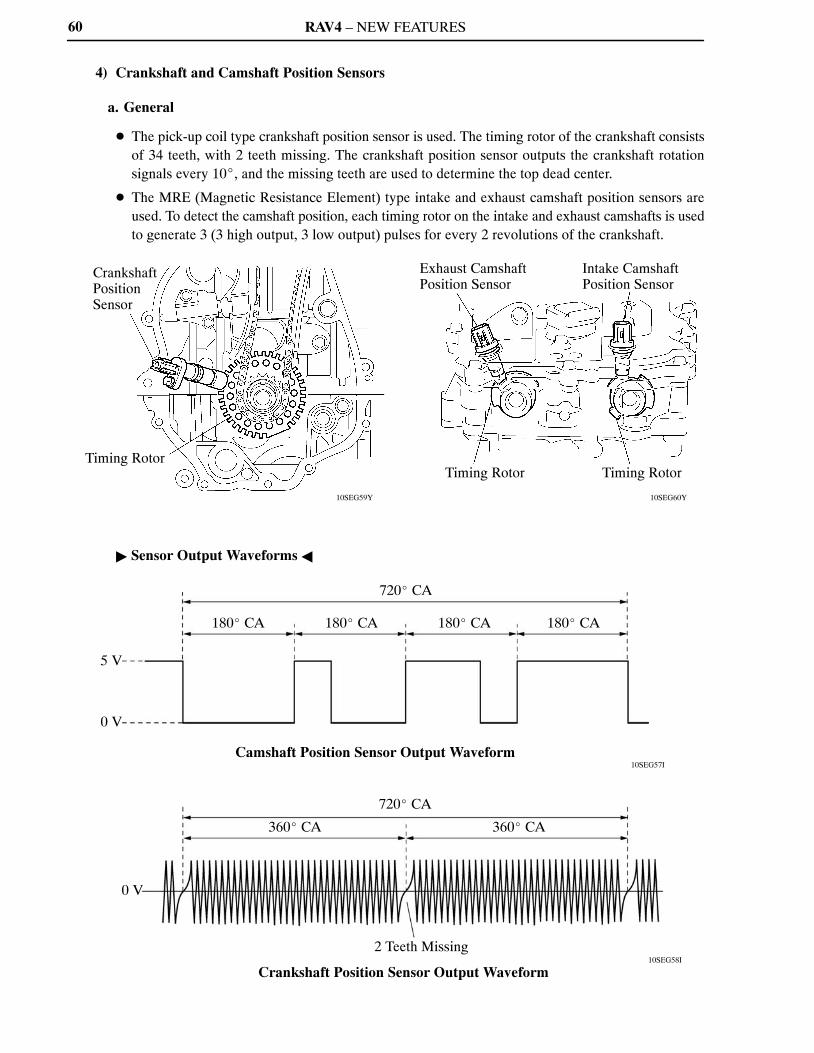
4) Crankshaft and Camshaft Position Sensors
a. General
� The pick-up coil type crankshaft position sensor is used. The timing rotor of the crankshaft consistsof 34 teeth, with 2 teeth missing. The crankshaft position sensor outputs the crankshaft rotationsignals every 10�, and the missing teeth are used to determine the top dead center.
� The MRE (Magnetic Resistance Element) type intake and exhaust camshaft position sensors areused. To detect the camshaft position, each timing rotor on the intake and exhaust camshafts is usedto generate 3 (3 high output, 3 low output) pulses for every 2 revolutions of the crankshaft.
� Sensor Output Waveforms �

RAV4 – NEW FEATURES
04FEG96Y
232CH41
Timing Rotor
Intake CamshaftPosition Sensor VCV1
G2
G2–
ECM
EngineSpeed
SensorOutput
MRE Type
Digital Output
Engine Speed
Sensor Output
No Detecting
Analog Output
Pick-up Coil Type
61
b. MRE Type Camshaft Position Sensor
� The MRE type camshaft position sensor consists of an MRE, a magnet and a sensor. The directionof the magnetic field changes due to the different shapes (protruded and non-protruded portions) ofthe timing rotor, which passes by the sensor. As a result, the resistance of the MRE changes, and theoutput voltage to the ECM changes to high or low. The ECM detects the camshaft position based onthis output voltage.
� The differences between the MRE type camshaft position sensor and the pick-up coil camshaftposition sensor used on the conventional model are as follows:
ItemSensor Type
MRE Pick-up Coil
Signal OutputConstant digital output starts fromlow engine speeds.
Analog output changes with theengine speed.
Camshaft PositionDetection
Detection is made by comparing theNE signals with the Hi/Lo outputswitch timing due to theprotruded/non-protruded portionsof the timing rotor, or made based onthe number of the input NE signalsduring Hi/Lo outputs.
Detection is made by comparing theNE signals with the change ofwaveform that is output when theprotruded portion of the timing rotorpasses.
� Wiring Diagram �
� MRE Type and Pick-up Coil Type Output Waveform Image Comparison �
RAV4 – NEW FEATURES
10SEG43Y
230LX12 238EG79
Throttle Body
Throttle Control Motor
Throttle Position Sensor Portion
Magnetic Yoke
Hall IC
Cross Section
Throttle Position Sensor
Magnetic Yoke
HallIC
HallIC
VTA1
ETA
VCTA
VTA2
ECM Output Voltage
(V)
5VTA2
VTA1
0 10 90 (�)
Fully Closed
Throttle Valve Opening Angle
Fully Open
Service Tip
The inspection method differs from the conventional contact type throttle position sensor becausethis non-contact type sensor uses a Hall IC.For details, refer to the 2009 RAV4 Repair Manual (Pub. No. RM10S0U).
62
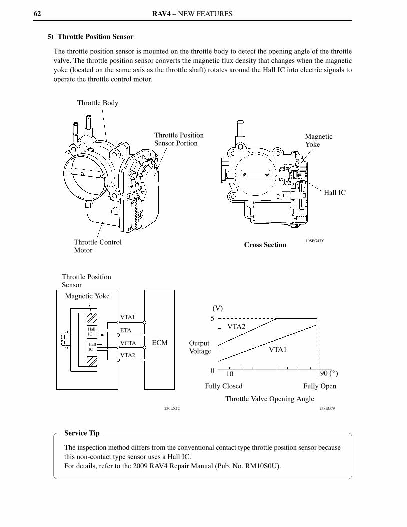
5) Throttle Position Sensor
The throttle position sensor is mounted on the throttle body to detect the opening angle of the throttlevalve. The throttle position sensor converts the magnetic flux density that changes when the magneticyoke (located on the same axis as the throttle shaft) rotates around the Hall IC into electric signals tooperate the throttle control motor.
RAV4 – NEW FEATURES
00SEG39Y
228TU24 228TU25
A
A
Internal Construction
Accelerator Pedal Arm
Magnetic YokeHall IC
A – A Cross Section
Accelerator Pedal Position Sensor
Magnetic Yoke
HallIC
HallIC
VPA
EPA
VCPA
VPA2
EPA2
VCP2
ECM
(V)
5
Output Voltage
0
Fully Closed
VPA2
VPA90�
Fully Open
Accelerator Pedal Depressed Angle
Service Tip
The inspection method differs from the conventional contact type accelerator pedal positionsensor because this non-contact type sensor uses a Hall IC.For details, refer to the 2009 RAV4 Repair Manual (Pub. No. RM10S0U).
63
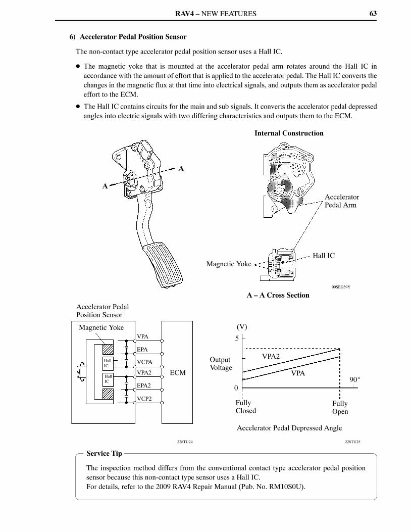
6) Accelerator Pedal Position Sensor
The non-contact type accelerator pedal position sensor uses a Hall IC.
� The magnetic yoke that is mounted at the accelerator pedal arm rotates around the Hall IC inaccordance with the amount of effort that is applied to the accelerator pedal. The Hall IC converts thechanges in the magnetic flux at that time into electrical signals, and outputs them as accelerator pedaleffort to the ECM.
� The Hall IC contains circuits for the main and sub signals. It converts the accelerator pedal depressedangles into electric signals with two differing characteristics and outputs them to the ECM.
RAV4 – NEW FEATURES
10SEG52Y10SEG51Y
10SEG53Y
Actuator
Hall IC
Magnetic Yoke
(V)
Output Voltage
Fully Closed Tumble Control Valve
Opening Angle
Fully Open
Magnetic Yoke
Magnet
Hall IC
VCIA
IAC1
EIA1
ECM
64
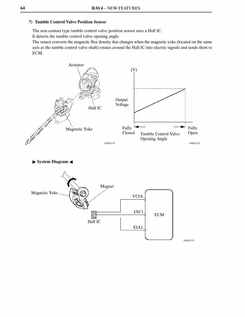
7) Tumble Control Valve Position Sensor
The non-contact type tumble control valve position sensor uses a Hall IC.It detects the tumble control valve opening angle.The sensor converts the magnetic flux density that changes when the magnetic yoke (located on the sameaxis as the tumble control valve shaft) rotates around the Hall IC into electric signals and sends them toECM.
� System Diagram �

RAV4 – NEW FEATURES
214CE04
: Conventional Type: Flat Type
(V)
Voltage
A
B
A: Detection Band ofConventional Type
B: Detection Band ofFlat Type
Frequency (Hz)
Characteristic of Knock Sensor
214CE01
Steel Weight
Insulator
PiezoelectricElement
Open/Short Circuit Detection Resistor
Flat Type Knock Sensor(Non-resonant Type)
214CE02
Piezoelectric Element
Vibration Plate
Conventional Type Knock Sensor(Resonant Type)
65
8) Knock Sensor (Flat Type)
a. General
In the conventional type knock sensor (resonant type), a vibration plate which has the same resonancepoint as the knocking frequency of the engine is built in and can detect the vibration in this frequencyband. On the other hand, a flat type knock sensor (non-resonant type) has the ability to detect vibrationin a wider frequency band from about 6 kHz to 15 kHz, and has the following features:
� The engine knocking frequency will change a bit depending on the engine speed. The flat type knocksensor can detect the vibration even when the engine knocking frequency is changed. Thus thevibration detection ability is increased compared to the conventional type knock sensor, and a moreprecise ignition timing control is possible.
b. Construction
� The flat type knock sensor is installed on the engine through the stud bolt installed on the cylinderblock. For this reason, a hole for the stud bolt runs through the center of the sensor.
� Inside the sensor, a steel weight is located on the upper portion and a piezoelectric element is locatedunder the weight through the insulator.
� The open/short circuit detection resistor is integrated.

RAV4 – NEW FEATURES
214CE08
Steel Weight
Inertia
Piezoelectric Element
214CE06
Knock Sensor
Piezoelectric Element
Open/Short Circuit Detection Resistor
200 kΩ
KNK1
EKNK
ECM
5 V
200 kΩ
IC
Service Tip
� In accordance with the use of an open/short circuit detection resistor, the inspection methodfor the sensor has been changed. For details, refer to the 2009 RAV4 Repair Manual (Pub.No. RM10S0U).
� To prevent water accumulation in the connecter, make sure to install the flat type knocksensor in the position shown in the following illustration:
10SEG66Y
7�
10�
Knock Sensor
66
c. Operation
The knocking vibration is transmitted to thesteel weight and its inertia applies pressureto the piezoelectric element. The actiongenerates electromotive force.
d. Open/Short Circuit Detection Resistor
While the ignition is ON, the open/short circuit detection resistor in the knock sensor and the resistorin the ECM keep constant the voltage at the terminal KNK1 of engine.An IC (Integrated Circuit) in the ECM is always monitoring the voltage of the terminal KNK1. If theopen/short circuit occurs between the knock sensor and the ECM, the voltage of the terminal KNK1will change and the ECM detects the open/short circuit and stores DTC (Diagnostic Trouble Code).
RAV4 – NEW FEATURES
10SEG44I
Accelerator Pedal Position Sensor
Mass Air Flow Meter
Cruise Control Switch
Throttle Valve
Throttle Position Sensor
Throttle ControlMotor
CAN (V Bus)
ECMSkid Control ECU
Ignition Coil
Fuel Injector
67
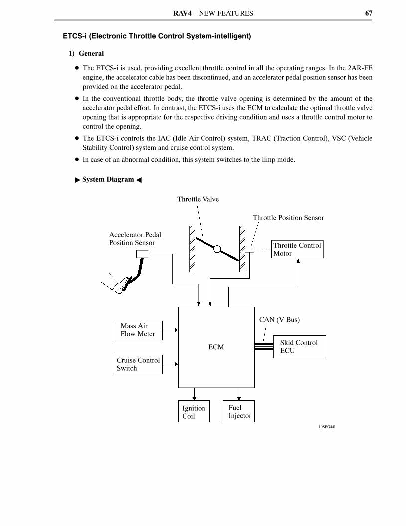
ETCS-i (Electronic Throttle Control System-intelligent)
1) General
� The ETCS-i is used, providing excellent throttle control in all the operating ranges. In the 2AR-FEengine, the accelerator cable has been discontinued, and an accelerator pedal position sensor has beenprovided on the accelerator pedal.
� In the conventional throttle body, the throttle valve opening is determined by the amount of theaccelerator pedal effort. In contrast, the ETCS-i uses the ECM to calculate the optimal throttle valveopening that is appropriate for the respective driving condition and uses a throttle control motor tocontrol the opening.
� The ETCS-i controls the IAC (Idle Air Control) system, TRAC (Traction Control), VSC (VehicleStability Control) system and cruise control system.
� In case of an abnormal condition, this system switches to the limp mode.
� System Diagram �
RAV4 – NEW FEATURES
10SEG45Y
Throttle Body
Throttle Position Sensor Portion
Reduction Gears
A
View from A
Throttle Valve
Cross Section
Magnetic Yoke
Hall IC
Throttle Control Motor
68
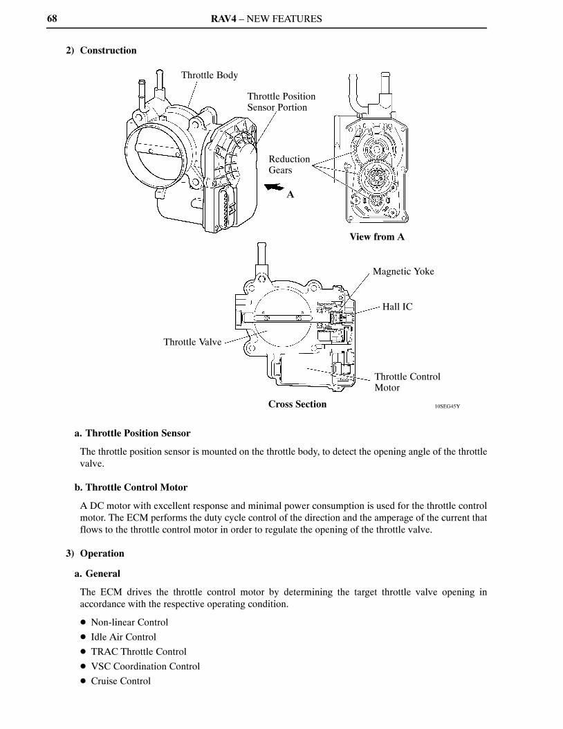
2) Construction
a. Throttle Position Sensor
The throttle position sensor is mounted on the throttle body, to detect the opening angle of the throttlevalve.
b. Throttle Control Motor
A DC motor with excellent response and minimal power consumption is used for the throttle controlmotor. The ECM performs the duty cycle control of the direction and the amperage of the current thatflows to the throttle control motor in order to regulate the opening of the throttle valve.
3) Operation
a. General
The ECM drives the throttle control motor by determining the target throttle valve opening inaccordance with the respective operating condition.
� Non-linear Control
� Idle Air Control
� TRAC Throttle Control
� VSC Coordination Control
� Cruise Control
RAV4 – NEW FEATURES
005EG13Y
Vehicle’s Longitudinal G
�
0
Throttle Valve Opening Angle
�
0
Accelerator Pedal Depressed Angle
�
0
: With Control: Without Control
Time �
69
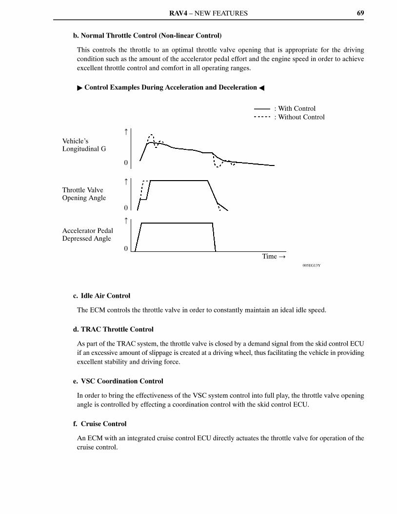
b. Normal Throttle Control (Non-linear Control)
This controls the throttle to an optimal throttle valve opening that is appropriate for the drivingcondition such as the amount of the accelerator pedal effort and the engine speed in order to achieveexcellent throttle control and comfort in all operating ranges.
� Control Examples During Acceleration and Deceleration �
c. Idle Air Control
The ECM controls the throttle valve in order to constantly maintain an ideal idle speed.
d. TRAC Throttle Control
As part of the TRAC system, the throttle valve is closed by a demand signal from the skid control ECUif an excessive amount of slippage is created at a driving wheel, thus facilitating the vehicle in providingexcellent stability and driving force.
e. VSC Coordination Control
In order to bring the effectiveness of the VSC system control into full play, the throttle valve openingangle is controlled by effecting a coordination control with the skid control ECU.
f. Cruise Control
An ECM with an integrated cruise control ECU directly actuates the throttle valve for operation of thecruise control.
RAV4 – NEW FEATURES
199EG45
Accelerator Pedal Position Sensor
MainSub Main
SubThrottlePositionSensor
Open
Throttle Valve Return Spring
Throttle Control Motor
Accelerator Pedal Throttle Body
ECM
199EG46
ECM
Accelerator Pedal Position Sensor
MainSub Main
SubThrottle Position Sensor
Close byReturn Spring
Throttle Valve Return Spring
Throttle Control Motor
Accelerator Pedal Throttle Body
70
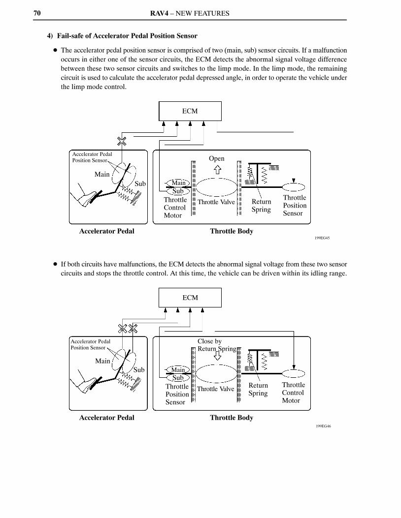
4) Fail-safe of Accelerator Pedal Position Sensor
� The accelerator pedal position sensor is comprised of two (main, sub) sensor circuits. If a malfunctionoccurs in either one of the sensor circuits, the ECM detects the abnormal signal voltage differencebetween these two sensor circuits and switches to the limp mode. In the limp mode, the remainingcircuit is used to calculate the accelerator pedal depressed angle, in order to operate the vehicle underthe limp mode control.
� If both circuits have malfunctions, the ECM detects the abnormal signal voltage from these two sensorcircuits and stops the throttle control. At this time, the vehicle can be driven within its idling range.
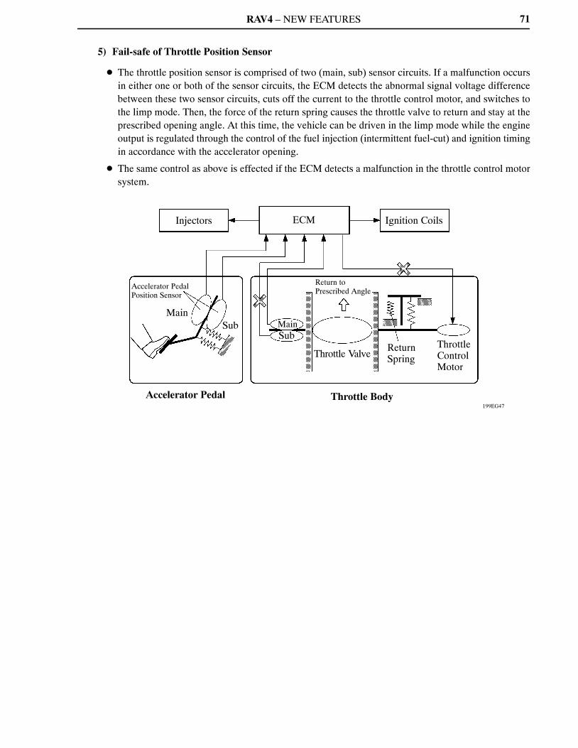
RAV4 – NEW FEATURES
199EG47
Injectors
Accelerator Pedal Position Sensor
MainSub
Accelerator Pedal
ECM
MainSub
Return to Prescribed Angle
Throttle Valve
Throttle Body
Ignition Coils
Return Spring
Throttle Control Motor
71
5) Fail-safe of Throttle Position Sensor
� The throttle position sensor is comprised of two (main, sub) sensor circuits. If a malfunction occursin either one or both of the sensor circuits, the ECM detects the abnormal signal voltage differencebetween these two sensor circuits, cuts off the current to the throttle control motor, and switches tothe limp mode. Then, the force of the return spring causes the throttle valve to return and stay at theprescribed opening angle. At this time, the vehicle can be driven in the limp mode while the engineoutput is regulated through the control of the fuel injection (intermittent fuel-cut) and ignition timingin accordance with the accelerator opening.
� The same control as above is effected if the ECM detects a malfunction in the throttle control motorsystem.

RAV4 – NEW FEATURES
10SEG67Y
Intake Camshaft Timing Oil Control Valve
Exhaust Camshaft Timing Oil Control Valve
Intake Camshaft Position Sensor
Exhaust Camshaft Position Sensor
Crankshaft Position Sensor
Engine Coolant Temperature Sensor
ECM
� Mass Air Flow Meter � Throttle Position
Sensor
221EG16
Crankshaft PositionSensor
Mass Air Flow Meter
Throttle Position Sensor
Engine Coolant Temp. Sensor
Camshaft Position Sensors
Vehicle Speed Signal
ECM
Target Valve Timing
Feedback
Correction
Actual Valve Timing
Duty Cycle Control
Camshaft Timing Oil Control Valves
72
Dual VVT-i (Variable Valve Timing-intelligent) System
1) General
� The Dual VVT-i system is designed to control the intake and exhaust camshafts within a range of 50�and 40� respectively (of Crankshaft Angle) to provide valve timing optimally suited to the enginecondition. This improves torque in all the speed ranges as well as increasing fuel economy, andreducing exhaust emissions.
� Using the engine speed, intake air mass, throttle position and engine coolant temperature, the ECMcan calculate optimal valve timing for each driving condition and controls the camshaft timing oilcontrol valve. In addition, the ECM uses signals from the camshaft position sensor and the crankshaftposition sensor to detect the actual valve timing, thus providing feedback control to achieve the targetvalve timing.
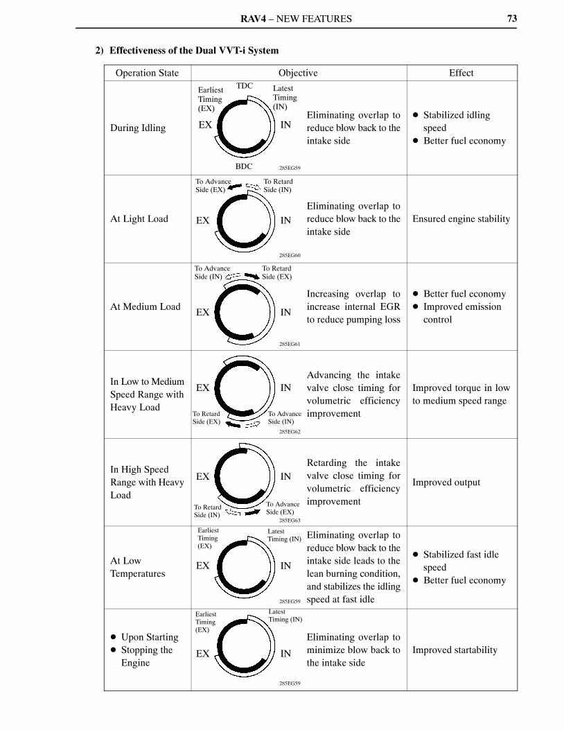
RAV4 – NEW FEATURES
285EG61
285EG62
285EG59
285EG59
285EG63
285EG60
285EG59
Earliest Timing (EX)
TDC Latest Timing (IN)
EX IN
BDC
To Advance Side (EX)
To Retard Side (IN)
EX IN
To Advance Side (IN)
To Retard Side (EX)
EX IN
EX IN
To Retard Side (EX)
To AdvanceSide (IN)
EX
IN
To Advance Side (EX)
Earliest Timing(EX)
Latest Timing (IN)
EX
IN
Earliest Timing(EX)
EX
Latest Timing (IN)
IN
To RetardSide (IN)
73
2) Effectiveness of the Dual VVT-i System
Operation State Objective Effect
During IdlingEliminating overlap toreduce blow back to theintake side
� Stabilized idling speed
� Better fuel economy
At Light LoadEliminating overlap toreduce blow back to theintake side
Ensured engine stability
At Medium LoadIncreasing overlap toincrease internal EGRto reduce pumping loss
� Better fuel economy� Improved emission
control
In Low to MediumSpeed Range withHeavy Load
Advancing the intakevalve close timing forvolumetric efficiencyimprovement
Improved torque in lowto medium speed range
In High SpeedRange with HeavyLoad
Retarding the intakevalve close timing forvolumetric efficiencyimprovement
Improved output
At LowTemperatures
Eliminating overlap toreduce blow back to theintake side leads to thelean burning condition,and stabilizes the idlingspeed at fast idle
� Stabilized fast idle speed
� Better fuel economy
� Upon Starting� Stopping the
Engine
Eliminating overlap tominimize blow back tothe intake side
Improved startability
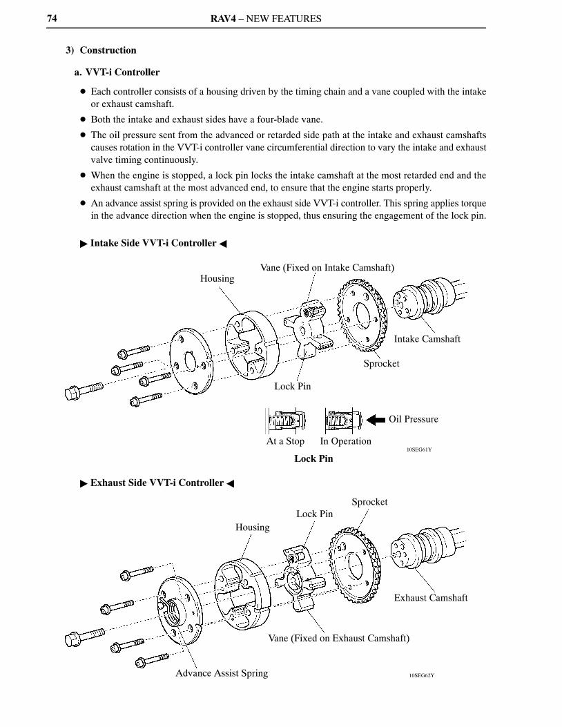
RAV4 – NEW FEATURES
10SEG61Y
10SEG62Y
HousingVane (Fixed on Intake Camshaft)
Lock Pin
Sprocket
Intake Camshaft
At a Stop
Lock Pin
In Operation
Oil Pressure
Housing
Lock Pin
Sprocket
Advance Assist Spring
Vane (Fixed on Exhaust Camshaft)
Exhaust Camshaft
74
3) Construction
a. VVT-i Controller
� Each controller consists of a housing driven by the timing chain and a vane coupled with the intakeor exhaust camshaft.
� Both the intake and exhaust sides have a four-blade vane.
� The oil pressure sent from the advanced or retarded side path at the intake and exhaust camshaftscauses rotation in the VVT-i controller vane circumferential direction to vary the intake and exhaustvalve timing continuously.
� When the engine is stopped, a lock pin locks the intake camshaft at the most retarded end and theexhaust camshaft at the most advanced end, to ensure that the engine starts properly.
� An advance assist spring is provided on the exhaust side VVT-i controller. This spring applies torquein the advance direction when the engine is stopped, thus ensuring the engagement of the lock pin.
� Intake Side VVT-i Controller �
� Exhaust Side VVT-i Controller �

RAV4 – NEW FEATURES
04FEG180Y
To VVT-i Controller(Advanced Side)*
Spring
SleeveDrain
Oil PressureDrain
Spool Valve
To VVT-i Controller(Retarded Side)*
75
b. Camshaft Timing Oil Control Valve
This camshaft timing oil control valve controls the spool valve using duty cycle control from the ECM.This allows hydraulic pressure to be applied to the VVT-i controller advanced or retarded side. Whenthe engine is stopped, the camshaft timing oil control valve is in the most retarded position.
*: On the exhaust side oil control valve, the advance and retard sides are reversed.
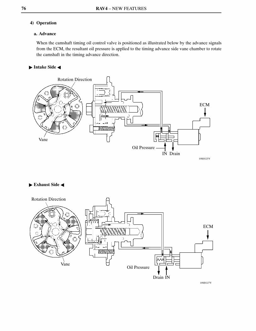
RAV4 – NEW FEATURES
10SEG25Y
10SEG27Y
Rotation Direction
Vane
Oil PressureIN Drain
ECM
Rotation Direction
VaneOil Pressure
Drain IN
ECM
76
4) Operation
a. Advance
When the camshaft timing oil control valve is positioned as illustrated below by the advance signalsfrom the ECM, the resultant oil pressure is applied to the timing advance side vane chamber to rotatethe camshaft in the timing advance direction.
� Intake Side �
� Exhaust Side �
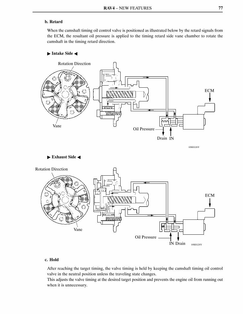
RAV4 – NEW FEATURES
10SEG26Y
10SEG28Y
Rotation Direction
VaneOil Pressure
Drain IN
ECM
Rotation Direction
Vane
Oil Pressure
IN Drain
ECM
77
b. Retard
When the camshaft timing oil control valve is positioned as illustrated below by the retard signals fromthe ECM, the resultant oil pressure is applied to the timing retard side vane chamber to rotate thecamshaft in the timing retard direction.
� Intake Side �
� Exhaust Side �
c. Hold
After reaching the target timing, the valve timing is held by keeping the camshaft timing oil controlvalve in the neutral position unless the traveling state changes.This adjusts the valve timing at the desired target position and prevents the engine oil from running outwhen it is unnecessary.
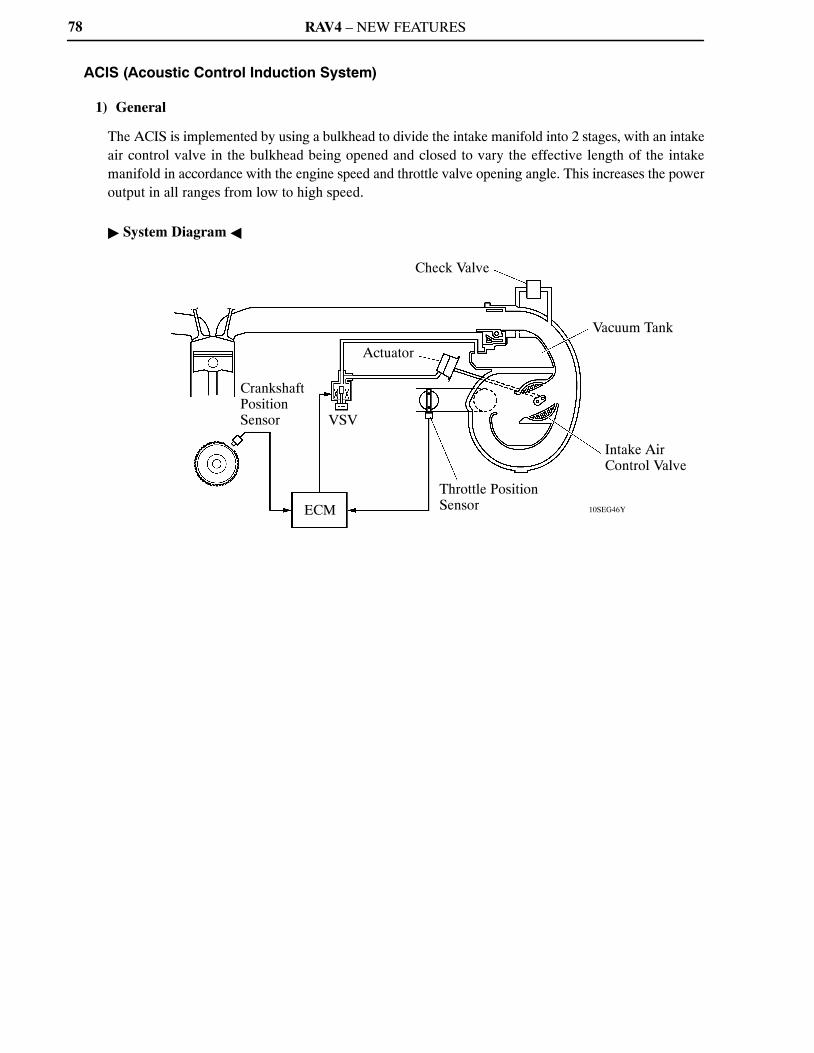
RAV4 – NEW FEATURES
10SEG46Y
Crankshaft Position Sensor
ECM
VSV
Actuator
Check Valve
Vacuum Tank
Intake Air Control Valve
Throttle Position Sensor
78
ACIS (Acoustic Control Induction System)
1) General
The ACIS is implemented by using a bulkhead to divide the intake manifold into 2 stages, with an intakeair control valve in the bulkhead being opened and closed to vary the effective length of the intakemanifold in accordance with the engine speed and throttle valve opening angle. This increases the poweroutput in all ranges from low to high speed.
� System Diagram �
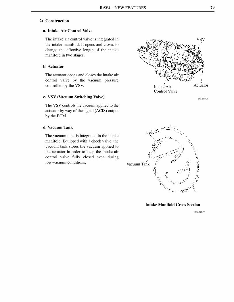
RAV4 – NEW FEATURES
10SEG70Y
10SEG40Y
VSV
Intake Air Control Valve
Actuator
Vacuum Tank
Intake Manifold Cross Section
79
2) Construction
a. Intake Air Control Valve
The intake air control valve is integrated inthe intake manifold. It opens and closes tochange the effective length of the intakemanifold in two stages.
b. Actuator
The actuator opens and closes the intake aircontrol valve by the vacuum pressurecontrolled by the VSV.
c. VSV (Vacuum Switching Valve)
The VSV controls the vacuum applied to theactuator by way of the signal (ACIS) outputby the ECM.
d. Vacuum Tank
The vacuum tank is integrated in the intakemanifold. Equipped with a check valve, thevacuum tank stores the vacuum applied tothe actuator in order to keep the intake aircontrol valve fully closed even duringlow-vacuum conditions.
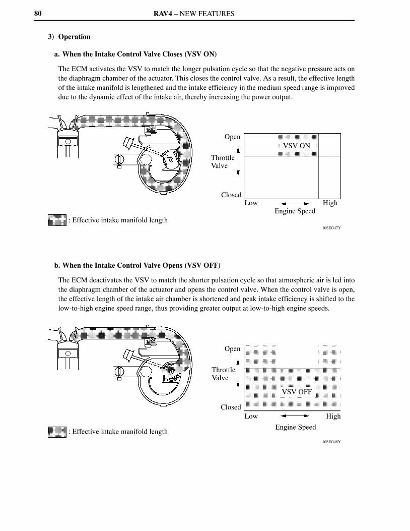
RAV4 – NEW FEATURES
10SEG47Y
Open
Throttle Valve
ClosedLow
VSV ON
Engine SpeedHigh
: Effective intake manifold length
10SEG48Y
: Effective intake manifold length
Open
Throttle Valve
ClosedLow
VSV OFF
Engine Speed
High
80
3) Operation
a. When the Intake Control Valve Closes (VSV ON)
The ECM activates the VSV to match the longer pulsation cycle so that the negative pressure acts onthe diaphragm chamber of the actuator. This closes the control valve. As a result, the effective lengthof the intake manifold is lengthened and the intake efficiency in the medium speed range is improveddue to the dynamic effect of the intake air, thereby increasing the power output.
b. When the Intake Control Valve Opens (VSV OFF)
The ECM deactivates the VSV to match the shorter pulsation cycle so that atmospheric air is led intothe diaphragm chamber of the actuator and opens the control valve. When the control valve is open,the effective length of the intake air chamber is shortened and peak intake efficiency is shifted to thelow-to-high engine speed range, thus providing greater output at low-to-high engine speeds.
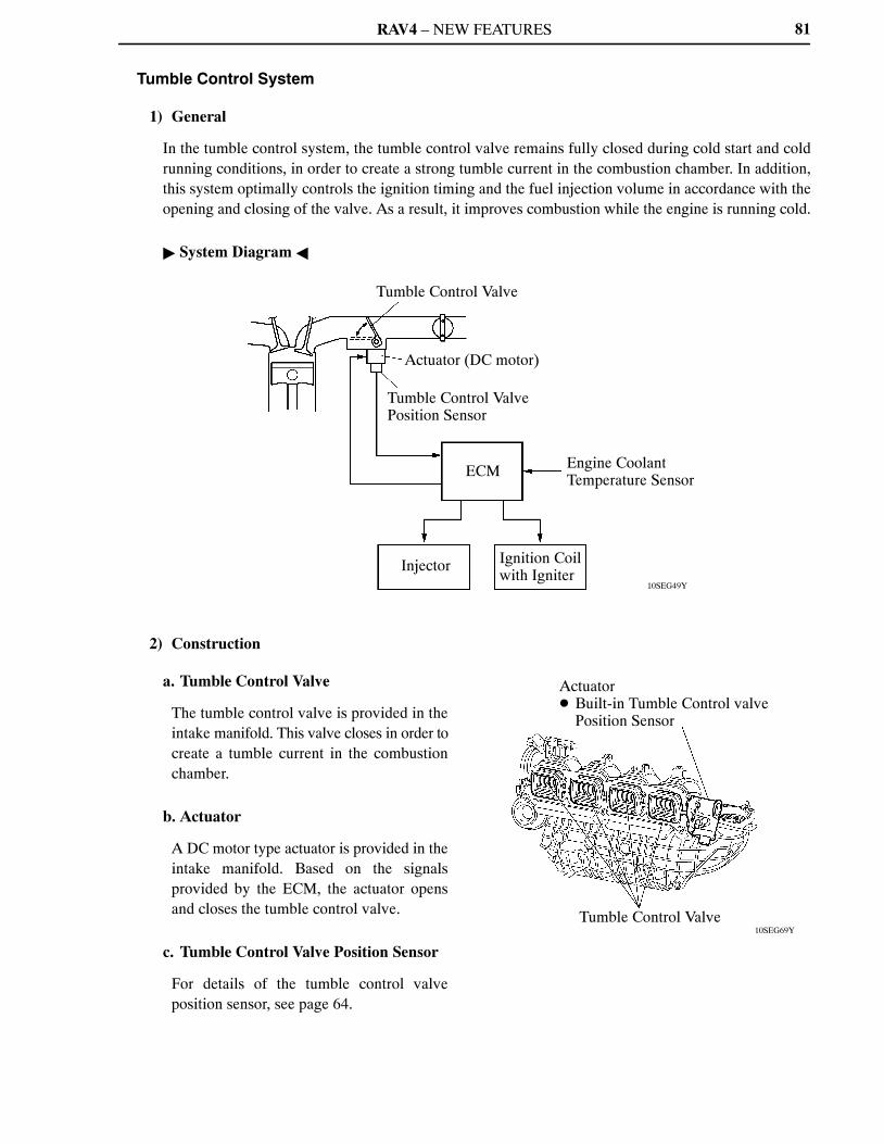
RAV4 – NEW FEATURES
10SEG49Y
Tumble Control Valve
Actuator (DC motor)
Tumble Control ValvePosition Sensor
ECM Engine CoolantTemperature Sensor
Injector Ignition Coilwith Igniter
10SEG69Y
Actuator � Built-in Tumble Control valve
Position Sensor
Tumble Control Valve
81
Tumble Control System
1) General
In the tumble control system, the tumble control valve remains fully closed during cold start and coldrunning conditions, in order to create a strong tumble current in the combustion chamber. In addition,this system optimally controls the ignition timing and the fuel injection volume in accordance with theopening and closing of the valve. As a result, it improves combustion while the engine is running cold.
� System Diagram �
2) Construction
a. Tumble Control Valve
The tumble control valve is provided in theintake manifold. This valve closes in order tocreate a tumble current in the combustionchamber.
b. Actuator
A DC motor type actuator is provided in theintake manifold. Based on the signalsprovided by the ECM, the actuator opensand closes the tumble control valve.
c. Tumble Control Valve Position Sensor
For details of the tumble control valveposition sensor, see page 64.
RAV4 – NEW FEATURES82
3) Operation
a. Engine Running Cold
To improve combustion, the ECM operates the actuator to fully close the tumble control valve, in orderto create a strong tumble current in the combustion chamber. This enables the engine to operate at a leanair-fuel ratio immediately after a cold start.Based on the signals from the various sensors, the ECM retards the ignition timing in order to reducethe amount of unburned gas and promote the warming up of the TWC. In addition, the ECM optimizesthe fuel injection volume.The vacuum pressure created downstream of the valve promotes the atomization of the fuel andprevents the fuel from adhering to the ports.These measures help reduce exhaust gas emissions while the engine is running cold.
b. Engine Warmed Up
The ECM operates the actuator to fully open the tumble control valve. When the valve is fully open,the passage has minimal intake resistance in order to improve engine performance.
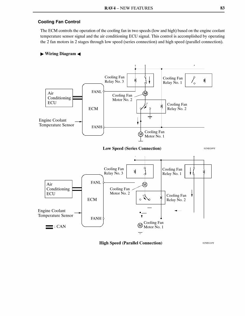
RAV4 – NEW FEATURES
01NEG09Y
AirConditioningECU
Engine Coolant Temperature Sensor
FANL
ECM
FANH
Cooling FanRelay No. 3
Cooling FanMotor No. 2
Cooling FanRelay No. 1
Cooling Fan Relay No. 2
Cooling Fan Motor No. 1
Low Speed (Series Connection)
01NEG10Y
Air ConditioningECU
Engine Coolant Temperature Sensor
: CAN
FANL
ECM
FANH
Cooling FanRelay No. 3
Cooling FanMotor No. 2
Cooling FanRelay No. 1
Cooling FanRelay No. 2
Cooling FanMotor No. 1
High Speed (Parallel Connection)
83
Cooling Fan Control
The ECM controls the operation of the cooling fan in two speeds (low and high) based on the engine coolanttemperature sensor signal and the air conditioning ECU signal. This control is accomplished by operatingthe 2 fan motors in 2 stages through low speed (series connection) and high speed (parallel connection).
� Wiring Diagram �
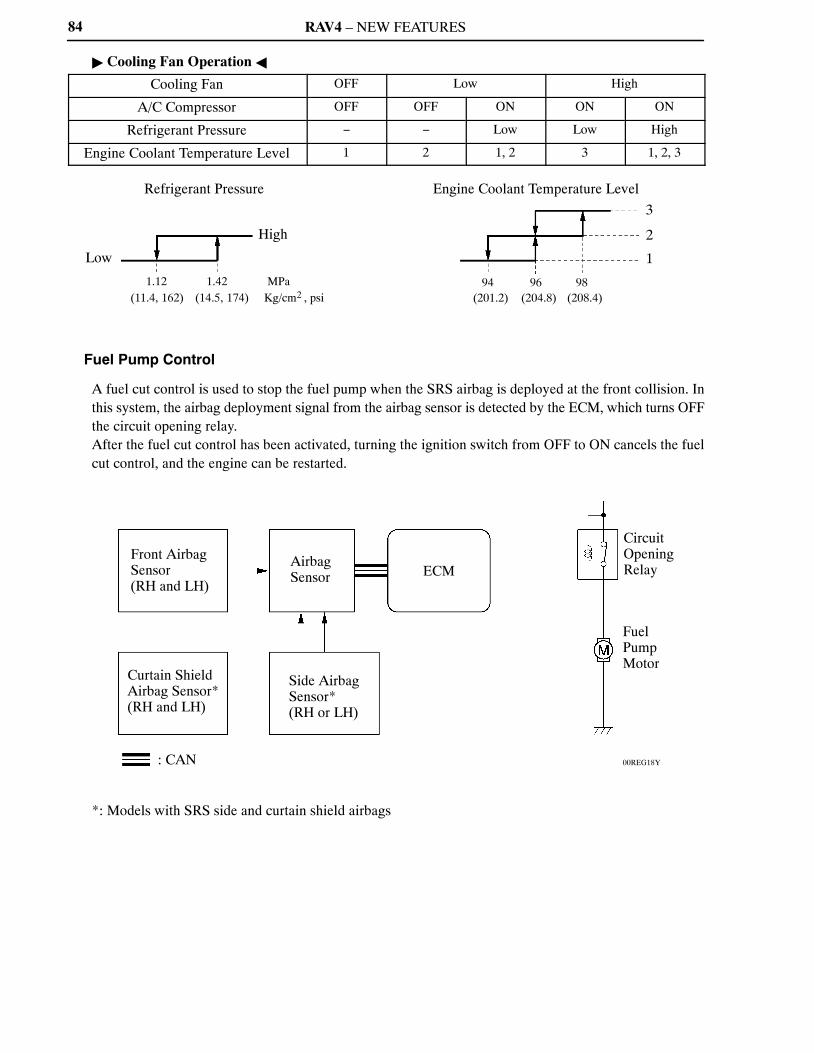
RAV4 – NEW FEATURES
3
2
1
Engine Coolant Temperature LevelRefrigerant Pressure
Low
High
1.12(11.4, 162)
1.42(14.5, 174)
MPaKg/cm2 , psi
94(201.2)
96(204.8)
98(208.4)
00REG18Y
Front AirbagSensor (RH and LH)
Curtain ShieldAirbag Sensor*(RH and LH)
: CAN
AirbagSensor
Side AirbagSensor* (RH or LH)
ECM
CircuitOpeningRelay
FuelPumpMotor
84
� Cooling Fan Operation �
Cooling Fan OFF Low High
A/C Compressor OFF OFF ON ON ON
Refrigerant Pressure − − Low Low High
Engine Coolant Temperature Level 1 2 1, 2 3 1, 2, 3
Fuel Pump Control
A fuel cut control is used to stop the fuel pump when the SRS airbag is deployed at the front collision. Inthis system, the airbag deployment signal from the airbag sensor is detected by the ECM, which turns OFFthe circuit opening relay.After the fuel cut control has been activated, turning the ignition switch from OFF to ON cancels the fuelcut control, and the engine can be restarted.
*: Models with SRS side and curtain shield airbags
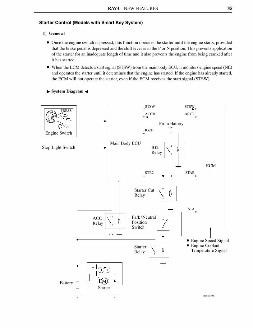
RAV4 – NEW FEATURES
06J0EG78C
PRESS
Engine Switch
Stop Light SwitchMain Body ECU
STSW
ACCR
STSW
ACCR
From BatteryIG2D
IG2Relay
STR2 STAR
ECM
Starter CutRelay
ACCRelay
Park/NeutralPosition Switch
STA
StarterRelay
� Engine Speed Signal� Engine Coolant
Temperature Signal
BatteryStarter
85
Starter Control (Models with Smart Key System)
1) General
� Once the engine switch is pressed, this function operates the starter until the engine starts, providedthat the brake pedal is depressed and the shift lever is in the P or N position. This prevents applicationof the starter for an inadequate length of time and it also prevents the engine from being cranked afterit has started.
� When the ECM detects a start signal (STSW) from the main body ECU, it monitors engine speed (NE)and operates the starter until it determines that the engine has started. If the engine has already started,the ECM will not operate the starter, even if the ECM receives the start signal (STSW).
� System Diagram �
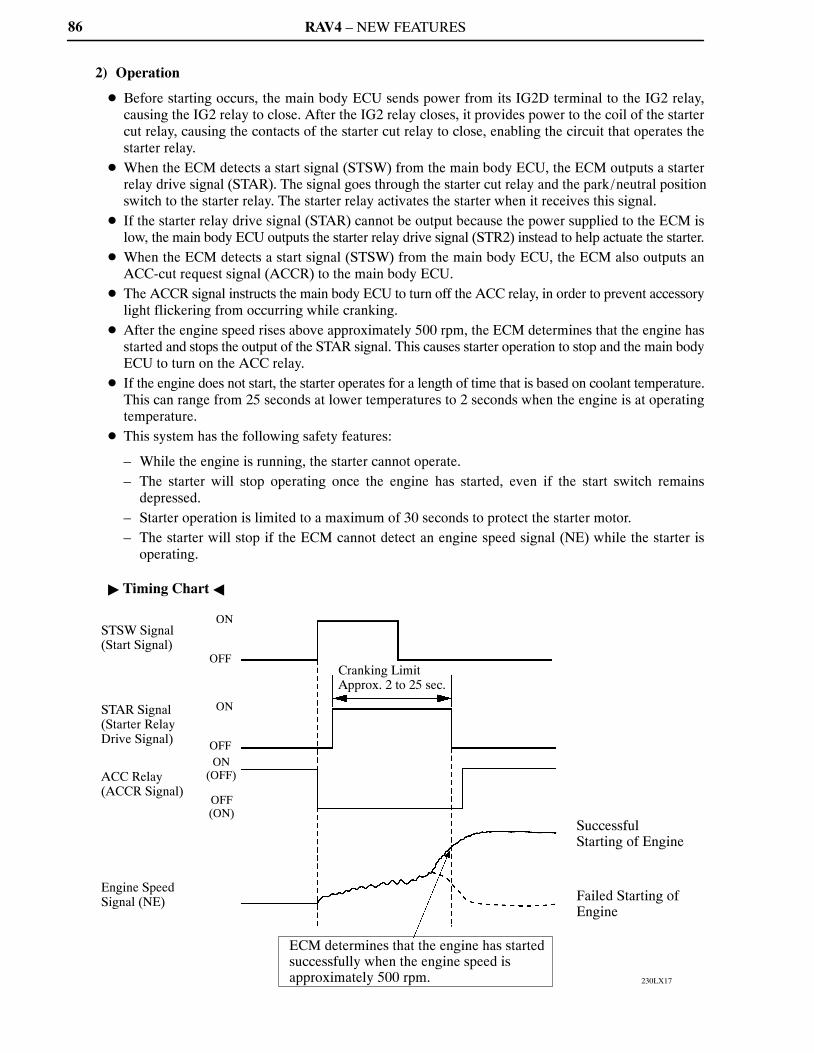
RAV4 – NEW FEATURES
230LX17
STSW Signal(Start Signal)
STAR Signal(Starter Relay Drive Signal)
ACC Relay(ACCR Signal)
Engine SpeedSignal (NE)
ON
OFF
ON
OFFON
(OFF)
OFF(ON)
Cranking LimitApprox. 2 to 25 sec.
ECM determines that the engine has startedsuccessfully when the engine speed isapproximately 500 rpm.
SuccessfulStarting of Engine
Failed Starting of Engine
86
2) Operation
� Before starting occurs, the main body ECU sends power from its IG2D terminal to the IG2 relay,causing the IG2 relay to close. After the IG2 relay closes, it provides power to the coil of the startercut relay, causing the contacts of the starter cut relay to close, enabling the circuit that operates thestarter relay.
� When the ECM detects a start signal (STSW) from the main body ECU, the ECM outputs a starterrelay drive signal (STAR). The signal goes through the starter cut relay and the park/neutral positionswitch to the starter relay. The starter relay activates the starter when it receives this signal.
� If the starter relay drive signal (STAR) cannot be output because the power supplied to the ECM islow, the main body ECU outputs the starter relay drive signal (STR2) instead to help actuate the starter.
� When the ECM detects a start signal (STSW) from the main body ECU, the ECM also outputs anACC-cut request signal (ACCR) to the main body ECU.
� The ACCR signal instructs the main body ECU to turn off the ACC relay, in order to prevent accessorylight flickering from occurring while cranking.
� After the engine speed rises above approximately 500 rpm, the ECM determines that the engine hasstarted and stops the output of the STAR signal. This causes starter operation to stop and the main bodyECU to turn on the ACC relay.
� If the engine does not start, the starter operates for a length of time that is based on coolant temperature.This can range from 25 seconds at lower temperatures to 2 seconds when the engine is at operatingtemperature.
� This system has the following safety features:
– While the engine is running, the starter cannot operate.– The starter will stop operating once the engine has started, even if the start switch remains
depressed.– Starter operation is limited to a maximum of 30 seconds to protect the starter motor.– The starter will stop if the ECM cannot detect an engine speed signal (NE) while the starter is
operating.
� Timing Chart �
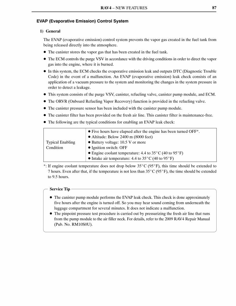
RAV4 – NEW FEATURES
Service Tip
� The canister pump module performs the EVAP leak check. This check is done approximatelyfive hours after the engine is turned off. So you may hear sound coming from underneath theluggage compartment for several minutes. It does not indicate a malfunction.
� The pinpoint pressure test procedure is carried out by pressurizing the fresh air line that runsfrom the pump module to the air filler neck. For details, refer to the 2009 RAV4 Repair Manual(Pub. No. RM10S0U).
87
EVAP (Evaporative Emission) Control System
1) General
The EVAP (evaporative emission) control system prevents the vapor gas created in the fuel tank frombeing released directly into the atmosphere.
� The canister stores the vapor gas that has been created in the fuel tank.
� The ECM controls the purge VSV in accordance with the driving conditions in order to direct the vaporgas into the engine, where it is burned.
� In this system, the ECM checks the evaporative emission leak and outputs DTC (Diagnostic TroubleCode) in the event of a malfunction. An EVAP (evaporative emission) leak check consists of anapplication of a vacuum pressure to the system and monitoring the changes in the system pressure inorder to detect a leakage.
� This system consists of the purge VSV, canister, refueling valve, canister pump module, and ECM.
� The ORVR (Onboard Refueling Vapor Recovery) function is provided in the refueling valve.
� The canister pressure sensor has been included with the canister pump module.
� The canister filter has been provided on the fresh air line. This canister filter is maintenance-free.
� The following are the typical conditions for enabling an EVAP leak check:
Typical EnablingCondition
� Five hours have elapsed after the engine has been turned OFF*.� Altitude: Below 2400 m (8000 feet)� Battery voltage: 10.5 V or more� Ignition switch: OFF� Engine coolant temperature: 4.4 to 35�C (40 to 95�F)� Intake air temperature: 4.4 to 35�C (40 to 95�F)
*: If engine coolant temperature does not drop below 35�C (95�F), this time should be extended to7 hours. Even after that, if the temperature is not less than 35�C (95�F), the time should be extendedto 9.5 hours.

RAV4 – NEW FEATURES
00REG22Y
To Intake Manifold
Purge VSV
Purge Air Line
ECM
Fuel Tank
Canister Filter
Fresh Air Line
Refueling Valve
Canister Pump Module
VentValve
Leak Detection Pump& Pump Motor
CanisterPressure Sensor
Canister
M
P
88
2) System Diagram

RAV4 – NEW FEATURES
10SEG54Y
Purge VSV
Intake Manifold
Purge VSV
Purge Line
Canister Pump Module� Canister Pressure Sensor� Leak Detection Pump� Vent Valve
Front
CanisterRefueling Valve
Air Filter
Fuel TankFresh Air Line
89
3) Layout of Main Components
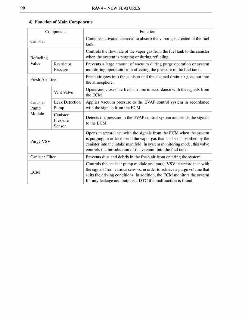
RAV4 – NEW FEATURES90
4) Function of Main Components
Component Function
CanisterContains activated charcoal to absorb the vapor gas created in the fueltank.
RefuelingValve
Controls the flow rate of the vapor gas from the fuel tank to the canisterwhen the system is purging or during refueling.
RestrictorPassage
Prevents a large amount of vacuum during purge operation or systemmonitoring operation from affecting the pressure in the fuel tank.
Fresh Air LineFresh air goes into the canister and the cleaned drain air goes out intothe atmosphere.
CanisterPumpModule
Vent ValveOpens and closes the fresh air line in accordance with the signals fromthe ECM.
Leak DetectionPump
Applies vacuum pressure to the EVAP control system in accordancewith the signals from the ECM.
CanisterPressureSensor
Detects the pressure in the EVAP control system and sends the signalsto the ECM.
Purge VSV
Opens in accordance with the signals from the ECM when the systemis purging, in order to send the vapor gas that has been absorbed by thecanister into the intake manifold. In system monitoring mode, this valvecontrols the introduction of the vacuum into the fuel tank.
Canister Filter Prevents dust and debris in the fresh air from entering the system.
ECM
Controls the canister pump module and purge VSV in accordance withthe signals from various sensors, in order to achieve a purge volume thatsuits the driving conditions. In addition, the ECM monitors the systemfor any leakage and outputs a DTC if a malfunction is found.
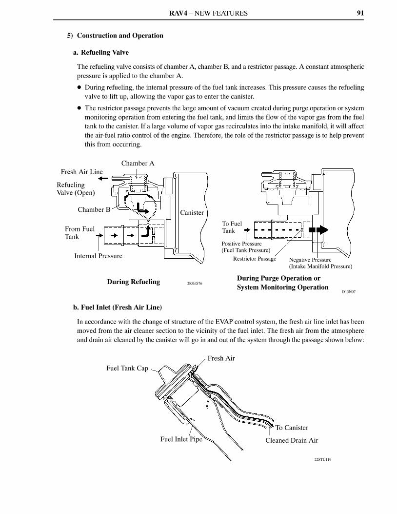
RAV4 – NEW FEATURES
D13N07
285EG76
Fresh Air Line
Refueling Valve (Open)
Chamber B
From FuelTank
Internal Pressure
Chamber A
Canister
During Refueling
To FuelTank
Positive Pressure (Fuel Tank Pressure)
Restrictor Passage Negative Pressure (Intake Manifold Pressure)
During Purge Operation or System Monitoring Operation
228TU119
Fuel Tank CapFresh Air
Fuel Inlet Pipe
To Canister
Cleaned Drain Air
91
5) Construction and Operation
a. Refueling Valve
The refueling valve consists of chamber A, chamber B, and a restrictor passage. A constant atmosphericpressure is applied to the chamber A.
� During refueling, the internal pressure of the fuel tank increases. This pressure causes the refuelingvalve to lift up, allowing the vapor gas to enter the canister.
� The restrictor passage prevents the large amount of vacuum created during purge operation or systemmonitoring operation from entering the fuel tank, and limits the flow of the vapor gas from the fueltank to the canister. If a large volume of vapor gas recirculates into the intake manifold, it will affectthe air-fuel ratio control of the engine. Therefore, the role of the restrictor passage is to help preventthis from occurring.
b. Fuel Inlet (Fresh Air Line)
In accordance with the change of structure of the EVAP control system, the fresh air line inlet has beenmoved from the air cleaner section to the vicinity of the fuel inlet. The fresh air from the atmosphereand drain air cleaned by the canister will go in and out of the system through the passage shown below:
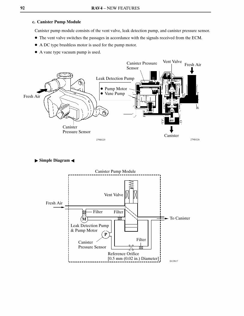
RAV4 – NEW FEATURES
279EG26279EG25
Fresh Air
Canister Pressure Sensor
Leak Detection Pump
� Pump Motor� Vane Pump
Canister PressureSensor
Vent ValveFresh Air
Canister
D13N17
Fresh Air
Canister Pump Module
Vent Valve
Filter Filter
M
Leak Detection Pump& Pump Motor
Canister Pressure Sensor
P
Reference Orifice [0.5 mm (0.02 in.) Diameter]
Filter
To Canister
92
c. Canister Pump Module
Canister pump module consists of the vent valve, leak detection pump, and canister pressure sensor.
� The vent valve switches the passages in accordance with the signals received from the ECM.
� A DC type brushless motor is used for the pump motor.
� A vane type vacuum pump is used.
� Simple Diagram �
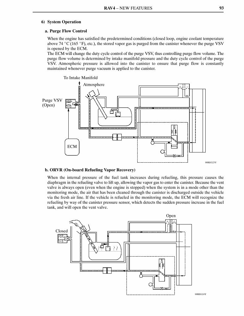
RAV4 – NEW FEATURES
00REG23Y
Purge VSV(Open)
To Intake Manifold
Atmosphere
ECM
00REG24Y
Closed
Open
93
6) System Operation
a. Purge Flow Control
When the engine has satisfied the predetermined conditions (closed loop, engine coolant temperatureabove 74 �C (165 �F), etc.), the stored vapor gas is purged from the canister whenever the purge VSVis opened by the ECM.The ECM will change the duty cycle control of the purge VSV, thus controlling purge flow volume. Thepurge flow volume is determined by intake manifold pressure and the duty cycle control of the purgeVSV. Atmospheric pressure is allowed into the canister to ensure that purge flow is constantlymaintained whenever purge vacuum is applied to the canister.
b. ORVR (On-board Refueling Vapor Recovery)
When the internal pressure of the fuel tank increases during refueling, this pressure causes thediaphragm in the refueling valve to lift up, allowing the vapor gas to enter the canister. Because the ventvalve is always open (even when the engine is stopped) when the system is in a mode other than themonitoring mode, the air that has been cleaned through the canister is discharged outside the vehiclevia the fresh air line. If the vehicle is refueled in the monitoring mode, the ECM will recognize therefueling by way of the canister pressure sensor, which detects the sudden pressure increase in the fueltank, and will open the vent valve.

RAV4 – NEW FEATURES
275TU47
PurgeVSV
VentValve
Pump Motor
ON (Open)
OFF (Closed)
ON
OFF (Vent)
ON
OFF
Atmospheric Pressure
SystemPressure
0.02 in. Leak Pressure
1) 2) 3) 4) 5) 6)
94
c. EVAP Leak Check
i) General
The EVAP leak check operates in accordance with the following timing chart:
� Timing Chart �
Order Operation Description Time
1)Atmospheric PressureMeasurement
The ECM turns the vent valve OFF (vent) and measuresthe EVAP control system pressure to memorizeatmospheric pressure.
10 sec.
2)0.02 in. Leak PressureMeasurement
The leak detection pump creates negative pressure(vacuum) through a 0.02 in. orifice and the pressure ismeasured. ECM determines this as 0.02 in. leak pressure.
60 sec.
3) EVAP Leak Check
The leak detection pump creates negative pressure(vacuum) in the EVAP control system and the EVAPcontrol system pressure is measured. If the stabilizedpressure is larger than the 0.02 in. leak pressure, the ECMdetermines the EVAP control system has a leakage.If EVAP control system pressure does not stabilize within12 minutes, the ECM cancels the EVAP monitor.
Within12 min.
4) Purge VSV MonitorThe ECM opens purge VSV and measures the EVAPcontrol system pressure increase. If the increase is large,the ECM interprets this as normal.
10 sec.
5)Repeat 0.02 in. LeakPressure Measurement
The leak detection pump creates negative pressure(vacuum) through a 0.02 in. orifice and pressure ismeasured. The ECM determines this as 0.02 in. leakpressure.
60 sec.
6) Final CheckThe ECM measures atmospheric pressure and records themonitor result.
—

RAV4 – NEW FEATURES
00REG25Y
D13N22
Purge VSV (OFF)
Atmosphere
ECM
Canister Pump Module
Vent Valve (OFF)
Leak Detection Pump& Pump Motor
Canister PressureSensor
M
P
Purge VSV
Vent Valve
Pump Motor
ON (Open)
OFF (Closed)
ON
OFF (Vent)
ON
OFF
Atmospheric Pressure
System Pressure
0.02 in. Leak Pressure
Atmospheric Pressure Measurement
95
ii) Atmospheric Pressure Measurement
1) When the ignition switch is turned OFF, the purge VSV and vent valve are turned OFF. Therefore,the atmospheric pressure is introduced into the canister.
2) The ECM measures the atmospheric pressure through the signals provided by the canister pressuresensor.
3) If the measurement value is out of standards, the ECM actuates the leak detection pump in orderto monitor the changes in the pressure.
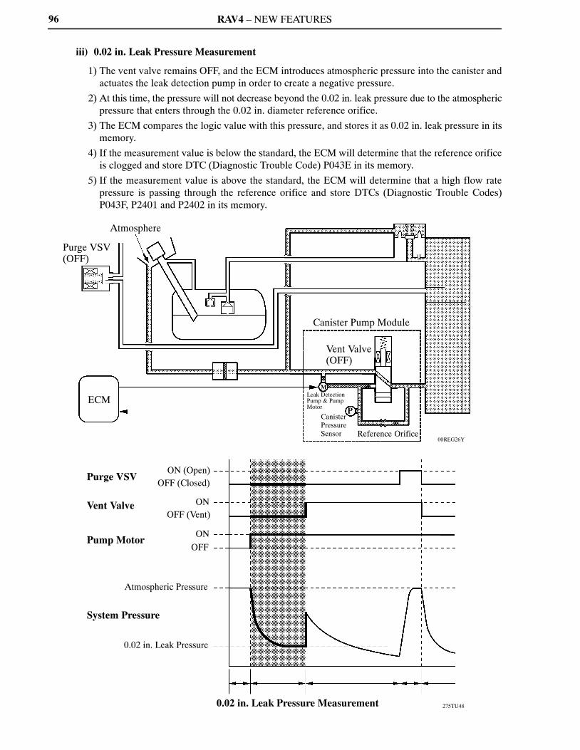
RAV4 – NEW FEATURES
00REG26Y
275TU48
Purge VSV(OFF)
Atmosphere
ECM
Canister Pump Module
Vent Valve (OFF)
Leak DetectionPump & PumpMotor
M
CanisterPressure Sensor
P
Reference Orifice
Purge VSV
Vent Valve
Pump Motor
ON (Open)OFF (Closed)
ONOFF (Vent)
ON
OFF
Atmospheric Pressure
System Pressure
0.02 in. Leak Pressure
0.02 in. Leak Pressure Measurement
96
iii) 0.02 in. Leak Pressure Measurement
1) The vent valve remains OFF, and the ECM introduces atmospheric pressure into the canister andactuates the leak detection pump in order to create a negative pressure.
2) At this time, the pressure will not decrease beyond the 0.02 in. leak pressure due to the atmosphericpressure that enters through the 0.02 in. diameter reference orifice.
3) The ECM compares the logic value with this pressure, and stores it as 0.02 in. leak pressure in itsmemory.
4) If the measurement value is below the standard, the ECM will determine that the reference orificeis clogged and store DTC (Diagnostic Trouble Code) P043E in its memory.
5) If the measurement value is above the standard, the ECM will determine that a high flow ratepressure is passing through the reference orifice and store DTCs (Diagnostic Trouble Codes)P043F, P2401 and P2402 in its memory.

RAV4 – NEW FEATURES
00REG27Y
275TU49
Purge VSV(OFF)
ECM
Atmosphere
Canister Pump Module
Vent Valve (ON)
MLeak Detection Pump& Pump Motor
PCanister PressureSensor Reference Orifice
Vacuum
Purge VSV
Vent Valve
Pump Motor
OFF (Closed)
ON (Open)
ON
ONOFF
Atmospheric Pressure
System Pressure
OFF (Vent)
0.02 in. Leak Pressure
P0455
P0456
Normal
EVAP Leak Check
97
iv) EVAP Leak Check
1) While actuating the leak detection pump, the ECM turns ON the vent valve in order to introducea vacuum into the canister.
2) When the pressure in the system stabilizes, the ECM compares this pressure with the 0.02 in. leakpressure in order to check for a leakage.
3) If the measurement value is below the 0.02 in. leak pressure, the ECM determines that there is noleakage.
4) If the measurement value is above the 0.02 in. leak pressure and near atmospheric pressure, theECM determines that there is a gross leakage (large hole) and stores DTC P0455 in its memory.
5) If the measurement value is above the 0.02 in. leak pressure, the ECM determines that there is asmall leakage and stores DTC P0456 in its memory.
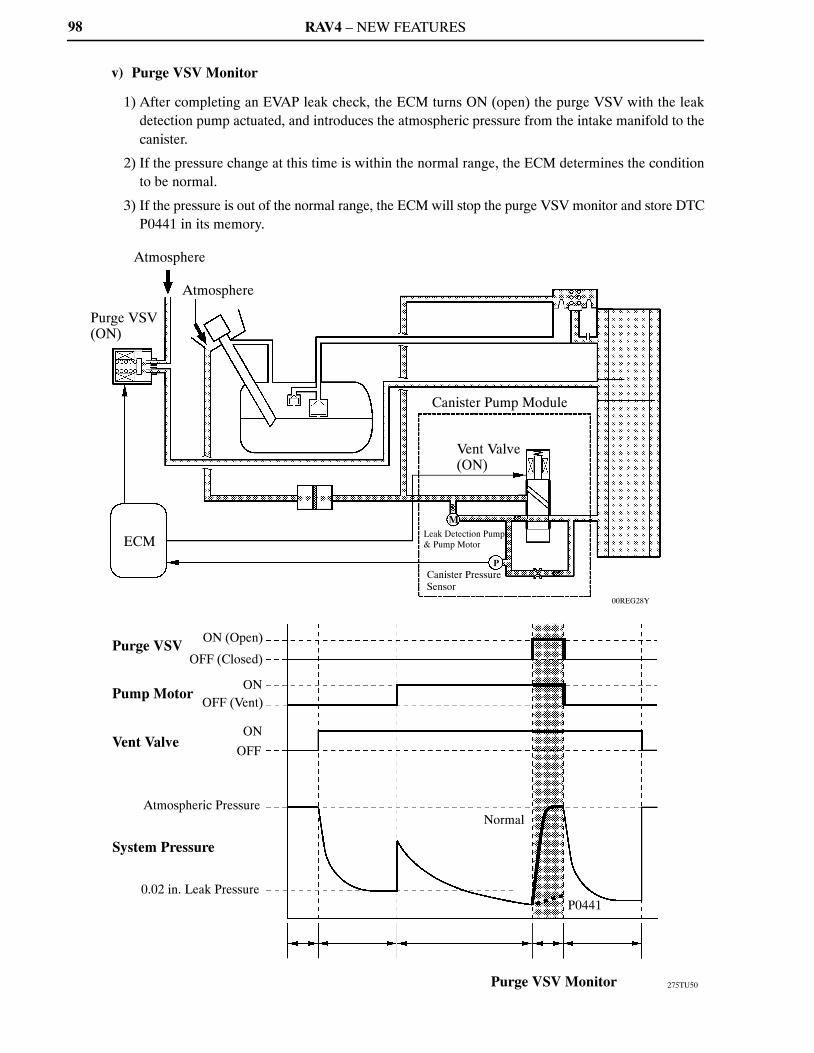
RAV4 – NEW FEATURES
00REG28Y
275TU50
Purge VSV (ON)
Atmosphere
Atmosphere
ECM
Canister Pump Module
Vent Valve (ON)
MLeak Detection Pump& Pump Motor
PCanister PressureSensor
Purge VSV
Vent Valve
Pump Motor
ON (Open)
OFF (Closed)
ONOFF (Vent)
ON
OFF
Atmospheric Pressure
System Pressure
Normal
Purge VSV Monitor
0.02 in. Leak PressureP0441
98
v) Purge VSV Monitor
1) After completing an EVAP leak check, the ECM turns ON (open) the purge VSV with the leakdetection pump actuated, and introduces the atmospheric pressure from the intake manifold to thecanister.
2) If the pressure change at this time is within the normal range, the ECM determines the conditionto be normal.
3) If the pressure is out of the normal range, the ECM will stop the purge VSV monitor and store DTCP0441 in its memory.

RAV4 – NEW FEATURES
01MEG03Y
275TU51
Purge VSV
Vent Valve
Pump Motor
ON (Open)
OFF (Closed)
ON
OFF (Vent)
ON
OFF
Atmospheric Pressure
System Pressure
Normal0.02 in. Leak Pressure
P0456
Purge VSV(OFF)
ECM
Atmosphere
Canister Pump Module
Vent Valve(OFF)
Leak DetectionPump & Pump Motor
M
P
Canister Pressure Sensor Reference Orifice
Repeat 0.02 in. Leak Pressure Measurement
99
vi) Repeat 0.02 in. Leak Pressure Measurement
1) While the ECM operates the vacuum pump, the purge VSV and vent valve turn off and a repeat 0.02in. leak pressure measurement is performed.
2) The ECM compares the measured pressure with the pressure during EVAP leak check.
3) If the pressure during the EVAP leak check is below the measured value, the ECM determines thatthere is no leakage.
4) If the pressure during the EVAP leak check is above the measured value, the ECM determines thatthere is a small leakage and stores DTC P0456 in its memory.
RAV4 – NEW FEATURES100
Diagnosis
� When the ECM detects a malfunction, it makes a diagnosis and memorizes the failed section.Furthermore, the MIL in the combination meter illuminates or blinks to inform the driver.
� The ECM will also store the DTCs of the malfunctions. The DTCs can be accessed by the use of theTechstream.
� A permanent DTC is used for the DTCs associated with the illumination of the MIL. The permanentDTCs can not be cleared by using the Techstream, disconnecting the battery terminal, or removing theEFI fuse.
� For details of the diagnosis and method to clear the DTCs, refer to the 2009 RAV4 Repair Manual (PubNo. RM10S0U).
Fail-safe
When a malfunction is detected by any of the sensors, there is a possibility of an engine or other malfunctionoccurring if the ECM continues to control the engine control system in the normal way. To prevent sucha problem, the fail-safe function of the ECM either relies on the data stored in memory to allow the enginecontrol system to continue operating, or stops the engine if a hazard is anticipated. For details, refer to the2009 RAV4 Repair Manual (Pub. No. RM10S0U).

RAV4 – NEW FEATURES 101
�U140F AND U241E AUTOMATIC TRANSAXLES
1. General
� The U140F and U241E 4-speed automatic transaxles are carried over on the models with the 2AR-FEengine. The basic construction and operation are the same as that of the previous models.
� The differential gear ratio has been changed.
� Specifications (U140F Automatic Transaxle) �
Model ’09 RAV4 ’08 RAV4
Transaxle Type U140F �
Engine Type 2AR-FE 2AZ-FE
Drive Type 4WD �
Gear Ratio*1
1st 3.938 �
2nd 2.194 �
3rd 1.411 �
4th 1.019 �
Reverse 3.141 �
Differential Gear Ratio 2.814 3.080
Fluid CapacityLiters
(US qts, Imp. qts)8.1 (8.56, 7.13) �
Fluid Type Toyota Genuine ATF WS �
Weight (Reference)*2 kg (lb) 94.9 (208.8) 98.0 (215.6)
*1: Counter gear ratio included*2: Weight shows the figure with the fluid fully filled.
� Specifications (U241E Automatic Transaxle) �
Model ’09 RAV4 ’08 RAV4
Transaxle Type U241E �
Engine Type 2AR-FE 2AZ-FE
Drive Type 2WD �
Gear Ratio*1
1st 3.943 �
2nd 2.197 �
3rd 1.413 �
4th 1.020 �
Reverse 3.145 �
Differential Gear Ratio 2.740 2.923
Fluid CapacityLiters
(US qts, Imp. qts) 8.1 (8.56, 7.13) �
Fluid Type Toyota Genuine ATF WS �
Weight (Reference)*2 kg (lb) 89.1 (196.0) 89.0 (195.8)
*1: Counter gear ratio included*2: Weight shows the figure with the fluid fully filled.
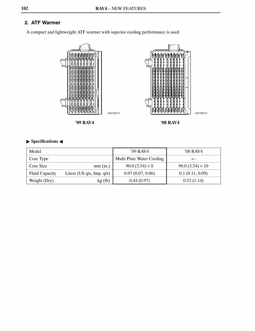
RAV4 – NEW FEATURES
10SCH002Y10SCH001Y
’09 RAV4 ’08 RAV4
102
2. ATF Warmer
A compact and lightweight ATF warmer with superior cooling performance is used.
� Specifications �
Model ’09 RAV4 ’08 RAV4
Core Type Multi Plate Water Cooling �
Core Size mm (in.) 90.0 (3.54) × 8 90.0 (3.54) × 10
Fluid Capacity Liters (US qts, Imp. qts) 0.07 (0.07, 0.06) 0.1 (0.11, 0.09)
Weight (Dry) kg (lb) 0.44 (0.97) 0.52 (1.14)
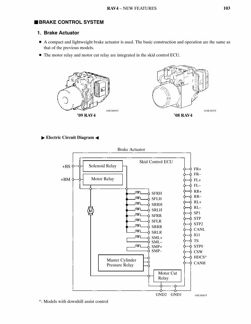
RAV4 – NEW FEATURES
01MCH29Y10SCH004Y
’09 RAV4 ’08 RAV4
10SCH005Y
Brake Actuator
+BS
+BM
Solenoid Relay
Motor Relay
Master CylinderPressure Relay
Skid Control ECU
SFRHSFLH
SRRHSRLHSFRRSFLRSRRRSRLRSML+SML–SMP+SMP–
Motor CutRelay
GND2 GND1
FR+FR–
FL+FL–
RR+RR–RL+RL–SP1STPSTP2CANLIG1
TSSTP0CSWHDCS*
CANH
103
�BRAKE CONTROL SYSTEM
1. Brake Actuator
� A compact and lightweight brake actuator is used. The basic construction and operation are the same asthat of the previous models.
� The motor relay and motor cut relay are integrated in the skid control ECU.
� Electric Circuit Diagram �
*: Models with downhill assist control
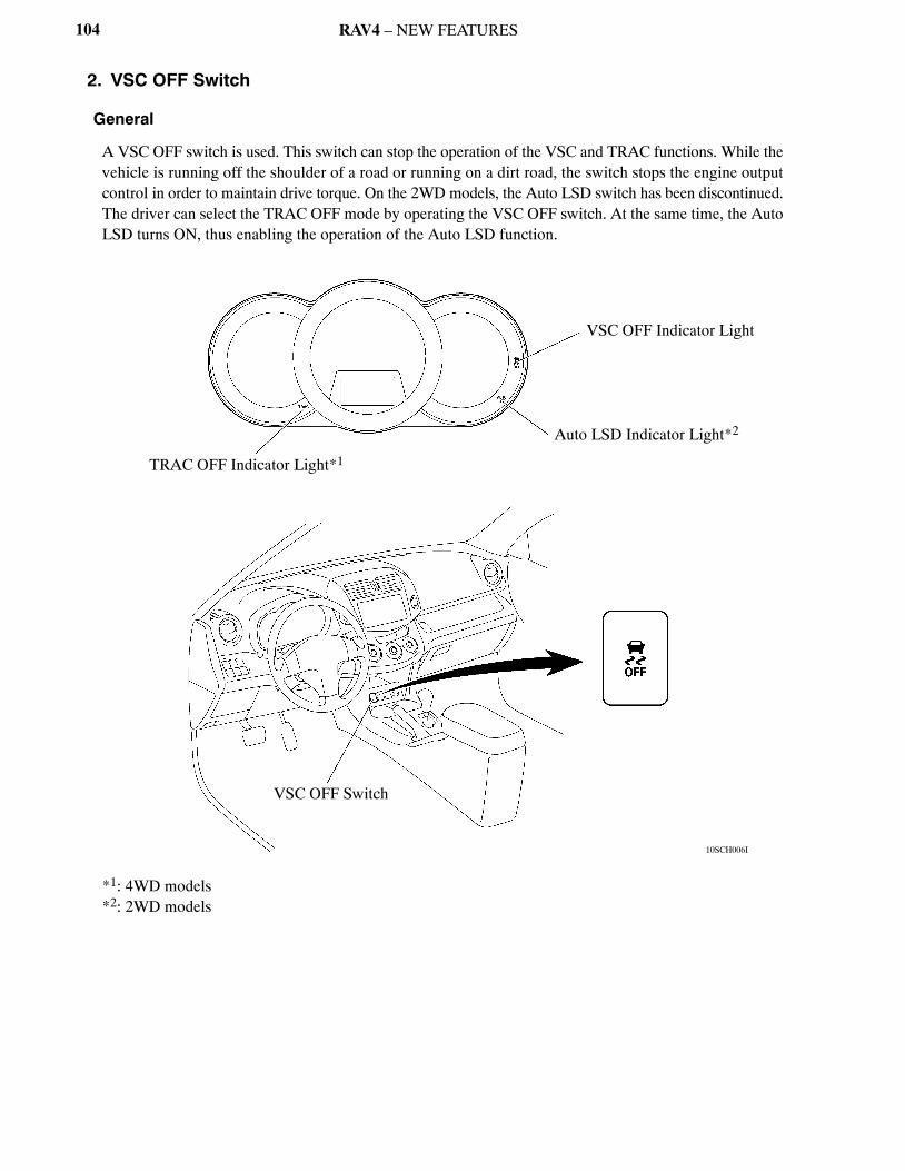
RAV4 – NEW FEATURES
10SCH006I
TRAC OFF Indicator Light*1
VSC OFF Indicator Light
Auto LSD Indicator Light*2
VSC OFF Switch
104
2. VSC OFF Switch
General
A VSC OFF switch is used. This switch can stop the operation of the VSC and TRAC functions. While thevehicle is running off the shoulder of a road or running on a dirt road, the switch stops the engine outputcontrol in order to maintain drive torque. On the 2WD models, the Auto LSD switch has been discontinued.The driver can select the TRAC OFF mode by operating the VSC OFF switch. At the same time, the AutoLSD turns ON, thus enabling the operation of the Auto LSD function.
*1: 4WD models*2: 2WD models
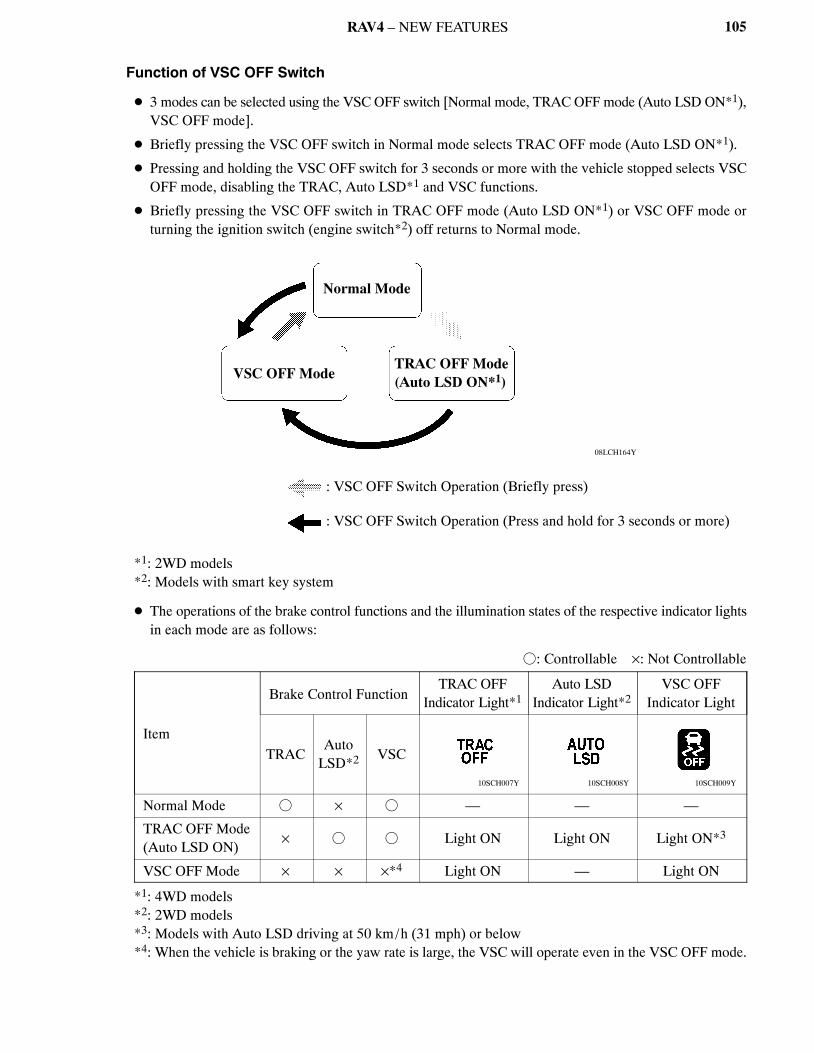
RAV4 – NEW FEATURES
08LCH164Y
Normal Mode
VSC OFF ModeTRAC OFF Mode(Auto LSD ON*1)
: VSC OFF Switch Operation (Briefly press)
: VSC OFF Switch Operation (Press and hold for 3 seconds or more)
10SCH009Y10SCH008Y10SCH007Y
105
Function of VSC OFF Switch
� 3 modes can be selected using the VSC OFF switch [Normal mode, TRAC OFF mode (Auto LSD ON*1),VSC OFF mode].
� Briefly pressing the VSC OFF switch in Normal mode selects TRAC OFF mode (Auto LSD ON*1).
� Pressing and holding the VSC OFF switch for 3 seconds or more with the vehicle stopped selects VSCOFF mode, disabling the TRAC, Auto LSD*1 and VSC functions.
� Briefly pressing the VSC OFF switch in TRAC OFF mode (Auto LSD ON*1) or VSC OFF mode orturning the ignition switch (engine switch*2) off returns to Normal mode.
*1: 2WD models*2: Models with smart key system
� The operations of the brake control functions and the illumination states of the respective indicator lightsin each mode are as follows:
�: Controllable ×: Not Controllable
Item
Brake Control FunctionTRAC OFF
Indicator Light*1Auto LSD
Indicator Light*2VSC OFF
Indicator Light
TRACAuto
LSD*2 VSC
Normal Mode � × � — — —
TRAC OFF Mode(Auto LSD ON)
× � � Light ON Light ON Light ON*3
VSC OFF Mode × × ×*4 Light ON — Light ON
*1: 4WD models*2: 2WD models*3: Models with Auto LSD driving at 50 km/h (31 mph) or below*4: When the vehicle is braking or the yaw rate is large, the VSC will operate even in the VSC OFF mode.
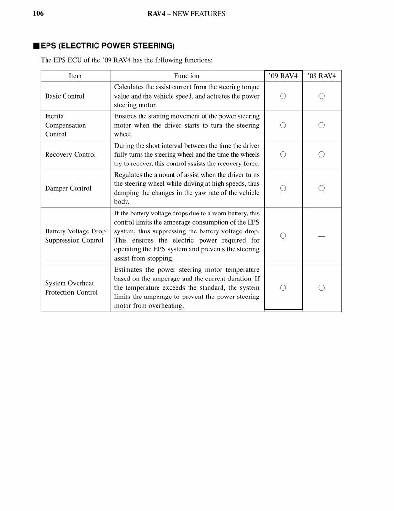
RAV4 – NEW FEATURES106
�EPS (ELECTRIC POWER STEERING)
The EPS ECU of the ’09 RAV4 has the following functions:
Item Function ’09 RAV4 ’08 RAV4
Basic ControlCalculates the assist current from the steering torquevalue and the vehicle speed, and actuates the powersteering motor.
� �
InertiaCompensationControl
Ensures the starting movement of the power steeringmotor when the driver starts to turn the steeringwheel.
� �
Recovery ControlDuring the short interval between the time the driverfully turns the steering wheel and the time the wheelstry to recover, this control assists the recovery force.
� �
Damper Control
Regulates the amount of assist when the driver turnsthe steering wheel while driving at high speeds, thusdamping the changes in the yaw rate of the vehiclebody.
� �
Battery Voltage DropSuppression Control
If the battery voltage drops due to a worn battery, thiscontrol limits the amperage consumption of the EPSsystem, thus suppressing the battery voltage drop.This ensures the electric power required foroperating the EPS system and prevents the steeringassist from stopping.
� —
System OverheatProtection Control
Estimates the power steering motor temperaturebased on the amperage and the current duration. Ifthe temperature exceeds the standard, the systemlimits the amperage to prevent the power steeringmotor from overheating.
� �

RAV4 – NEW FEATURES
10SBO002Y
10SBO003Y
Headrest
Upper Unit
Cable
Lower Unit
Headrest
Upper Unit
Cable
Lower Unit
Normal Position Operating Position
107
�FRONT SEAT
� The active headrest mechanism is used in the front seat headrest.
� Active headrests are provided, which move up and forward almost instantly in the event of a rear-endcollision when the force of the occupant body is applied to the seat back and reduce the distance betweenthe occupant’s head and the headrest.
� The active headrest consists of the lower unit, cable and upper unit.When the lower unit built into the seat back is pressed by the occupant’s lumbar as the occupant’s bodyslides down during a rear-end collision, the cable is pulled and the headrest is moved up and forward bythe upper unit, reducing the distance between the occupant’s head and the headrest.

RAV4 – NEW FEATURES
10SBE01Y
Engine Switch*1
Ignition Switch*2
Light ControlSwitch
Automatic LightControl Sensor
Main BodyECU(InstrumentPanelJunctionBlock)
Headlight Relay
Taillight Relay
Front Fog LightRelay
Headlight
Taillight
Front Fog light
108
�LIGHTINGAutomatic Light Control System
1) General
� The automatic light control system is used.
� When the light control switch is in the AUTO position, the automatic light control sensor detects theambient light and automatically turns the headlights, taillights and front fog lights ON or OFFaccordingly.
� The automatic light control sensor is integrated with the solar sensor that is used in the automatic airconditioning system.
� This system is controlled by the main body ECU.
� System Diagram �
*1: Models with smart key system*2: Models without smart key system

RAV4 – NEW FEATURES
10SBE02Y
10SBE03Y
Headlight Relay
HeadlightHeadlight
Front Fog Light Front Fog Light Taillight Taillight
Automatic Light Control Sensor
� Main Body ECU(Instrument Panel Junction Block)
� Taillight Relay� Front Fog Light Relay
Light Control Switch
Ignition Switch*2
Engine Switch*1
109
2) Layout of Main Components
*1: Models with smart key system*2: Models without smart key system
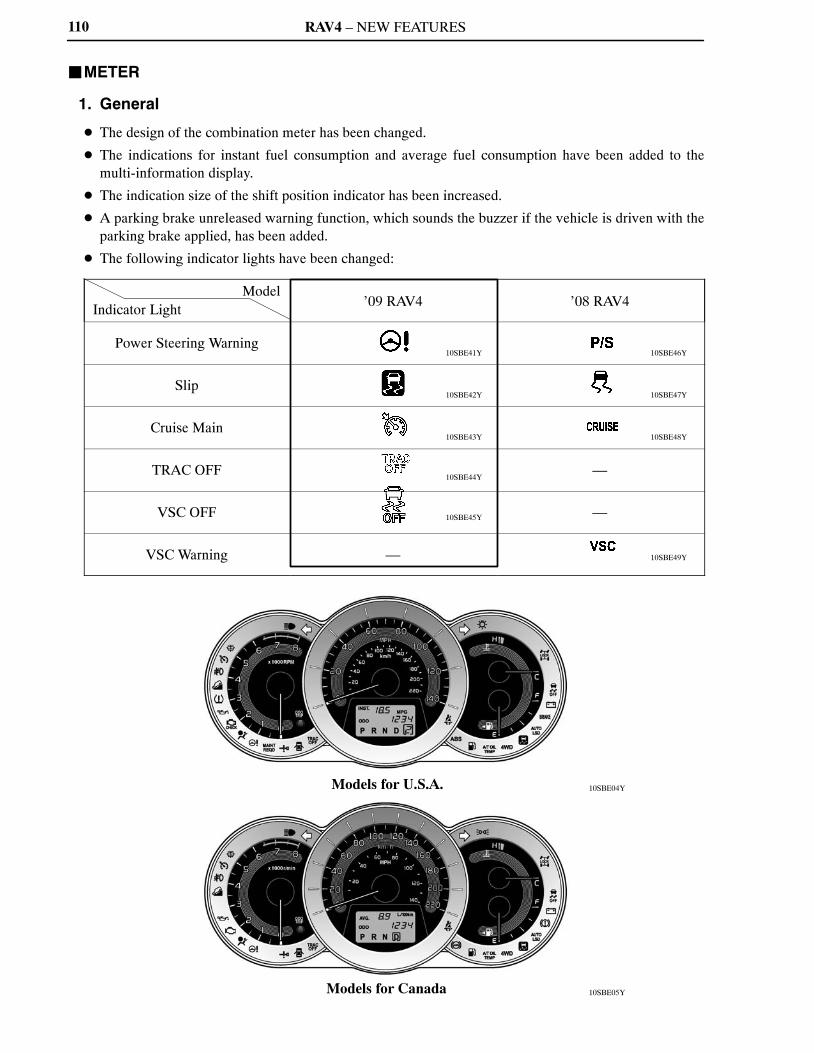
RAV4 – NEW FEATURES
10SBE05Y
10SBE04YModels for U.S.A.
Models for Canada
110
�METER
1. General
� The design of the combination meter has been changed.
� The indications for instant fuel consumption and average fuel consumption have been added to themulti-information display.
� The indication size of the shift position indicator has been increased.
� A parking brake unreleased warning function, which sounds the buzzer if the vehicle is driven with theparking brake applied, has been added.
� The following indicator lights have been changed:
ModelIndicator Light
’09 RAV4 ’08 RAV4
Power Steering Warning
Slip
Cruise Main
TRAC OFF —
VSC OFF —
VSC Warning —
10SBE41Y
10SBE42Y
10SBE43Y
10SBE44Y
10SBE45Y
10SBE46Y
10SBE47Y
10SBE48Y
10SBE49Y
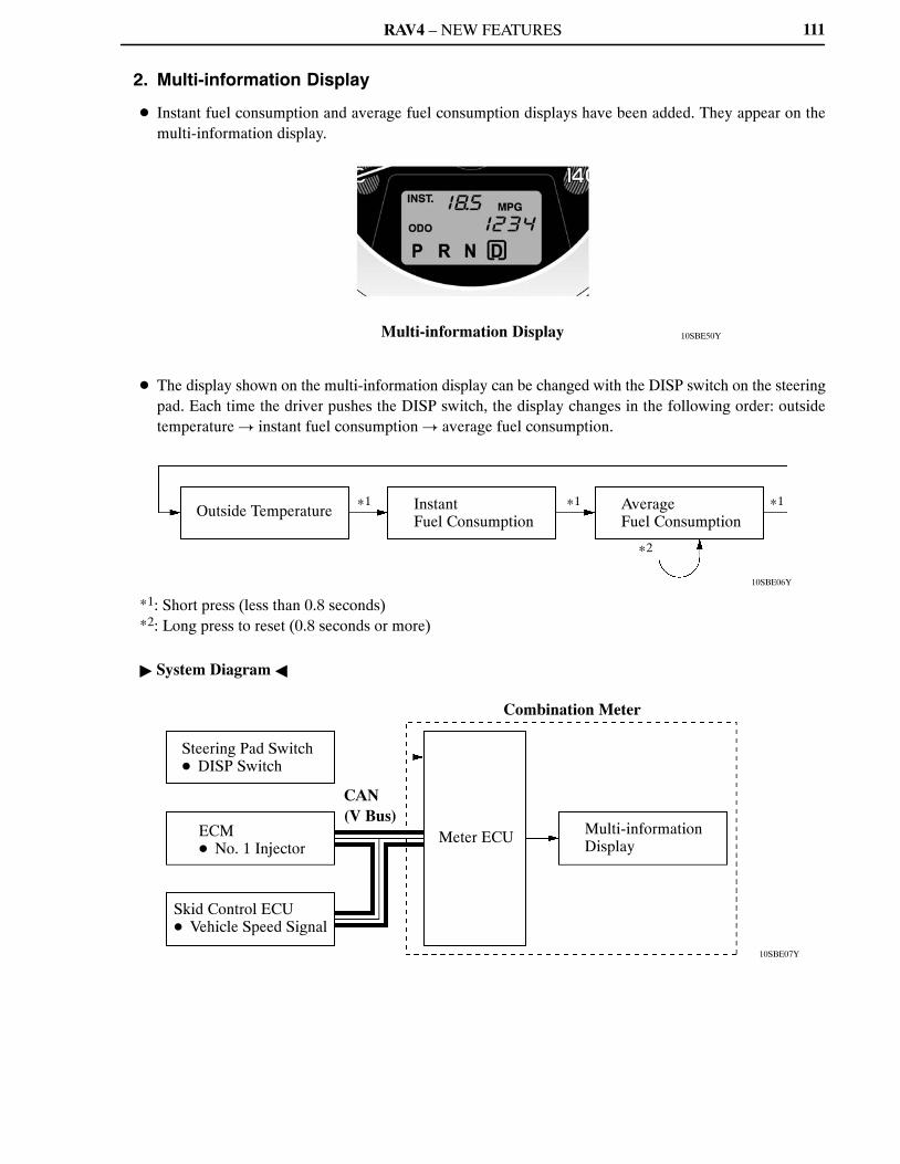
RAV4 – NEW FEATURES
10SBE50YMulti-information Display
10SBE06Y
Outside Temperature *1 Instant Fuel Consumption
*1 AverageFuel Consumption
*1
*2
10SBE07Y
Steering Pad Switch� DISP Switch
ECM� No. 1 Injector
Skid Control ECU� Vehicle Speed Signal
CAN (V Bus)
Combination Meter
Meter ECU Multi-informationDisplay
111
2. Multi-information Display
� Instant fuel consumption and average fuel consumption displays have been added. They appear on themulti-information display.
� The display shown on the multi-information display can be changed with the DISP switch on the steeringpad. Each time the driver pushes the DISP switch, the display changes in the following order: outsidetemperature � instant fuel consumption � average fuel consumption.
*1: Short press (less than 0.8 seconds)*2: Long press to reset (0.8 seconds or more)
� System Diagram �
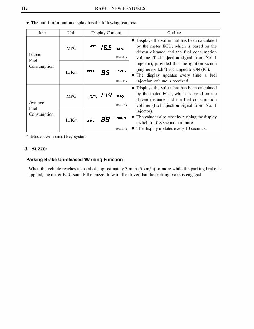
RAV4 – NEW FEATURES
10SBE08Y
10SBE09Y
10SBE10Y
10SBE11Y
112
� The multi-information display has the following features:
Item Unit Display Content Outline
InstantFuelConsumption
MPG
� Displays the value that has been calculatedby the meter ECU, which is based on thedriven distance and the fuel consumptionvolume (fuel injection signal from No. 1injector), provided that the ignition switch(engine switch*) is changed to ON (IG).
� The display updates every time a fuelinjection volume is received.
L/Km
AverageFuelConsumption
MPG
� Displays the value that has been calculatedby the meter ECU, which is based on thedriven distance and the fuel consumptionvolume (fuel injection signal from No. 1injector).
� The value is also reset by pushing the displayswitch for 0.8 seconds or more.
� The display updates every 10 seconds.
L/Km
*: Models with smart key system
3. Buzzer
Parking Brake Unreleased Warning Function
When the vehicle reaches a speed of approximately 3 mph (5 km/h) or more while the parking brake isapplied, the meter ECU sounds the buzzer to warn the driver that the parking brake is engaged.

RAV4 – NEW FEATURES
10SBE12YTSE17 Type A/C Compressor
10SBE13Y
113
�AIR CONDITIONING
1. General
� A TSE17 type A/C compressor is used for models with the 2AR-FE engine.
� The design of the switches on the automatic control type heater control panel has been changed.
2. A/C Compressor
� The TSE17 type A/C compressor has the following features:
– A refrigerant flow volume sensor is used for calculating the torque of the A/C compressor.
– A signal from the refrigerant flow volume sensor to the air conditioning amplifier has been added.
– An oil separator is used in order to reduce the volume of compressor oil that circulates in the system.
– A variable suction side throtole, which adjusts the size of the refrigerant passage, is used to reduce thenoise created during operation.
– A CS valve is integrated in the control valve in order to quickly discharge the liquid refrigerant thataccumulates in the A/C compressor. This suppresses the performance drop during the initial stages ofoperation even after the vehicle is left parked for a long time.
– A new, plastic DL type A/C pulley, which is lighter than the previous type, is used.
3. Automatic Control Type Heater Control Panel
The design of the switches on the automatic control type heater control panel has been changed.
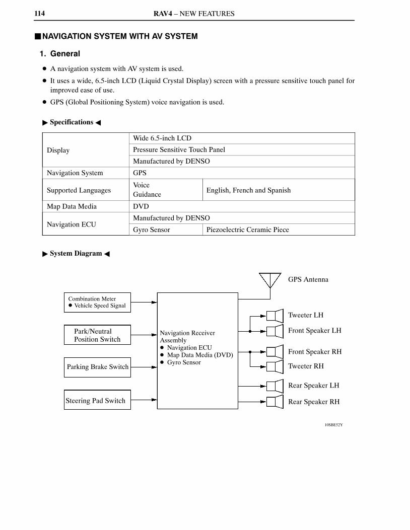
RAV4 – NEW FEATURES
10SBE52Y
Combination Meter� Vehicle Speed Signal
Park/NeutralPosition Switch
Parking Brake Switch
Steering Pad Switch
Navigation Receiver Assembly� Navigation ECU� Map Data Media (DVD)� Gyro Sensor
GPS Antenna
Front Speaker LH
Front Speaker RH
Tweeter LH
Tweeter RH
Rear Speaker RH
Rear Speaker LH
114
�NAVIGATION SYSTEM WITH AV SYSTEM
1. General
� A navigation system with AV system is used.
� It uses a wide, 6.5-inch LCD (Liquid Crystal Display) screen with a pressure sensitive touch panel forimproved ease of use.
� GPS (Global Positioning System) voice navigation is used.
� Specifications �
Display
Wide 6.5-inch LCD
Pressure Sensitive Touch Panel
Manufactured by DENSO
Navigation System GPS
Supported LanguagesVoiceGuidance
English, French and Spanish
Map Data Media DVD
Navigation ECUManufactured by DENSO
Gyro Sensor Piezoelectric Ceramic Piece
� System Diagram �

RAV4 – NEW FEATURES
10SBE23Y
Combination Meter
GPS Antenna
Steering Pad Switch
Rear Speaker LH
Parking Brake Switch
Navigation Receiver Assembly� Navigation ECU� Map Data Media (DVD)
Park/NeutralPosition Switch
Front Speaker LH
Tweeter LH
Tweeter RH
Front Speaker RH
Rear Speaker RH
115
2. Layout of Main Components
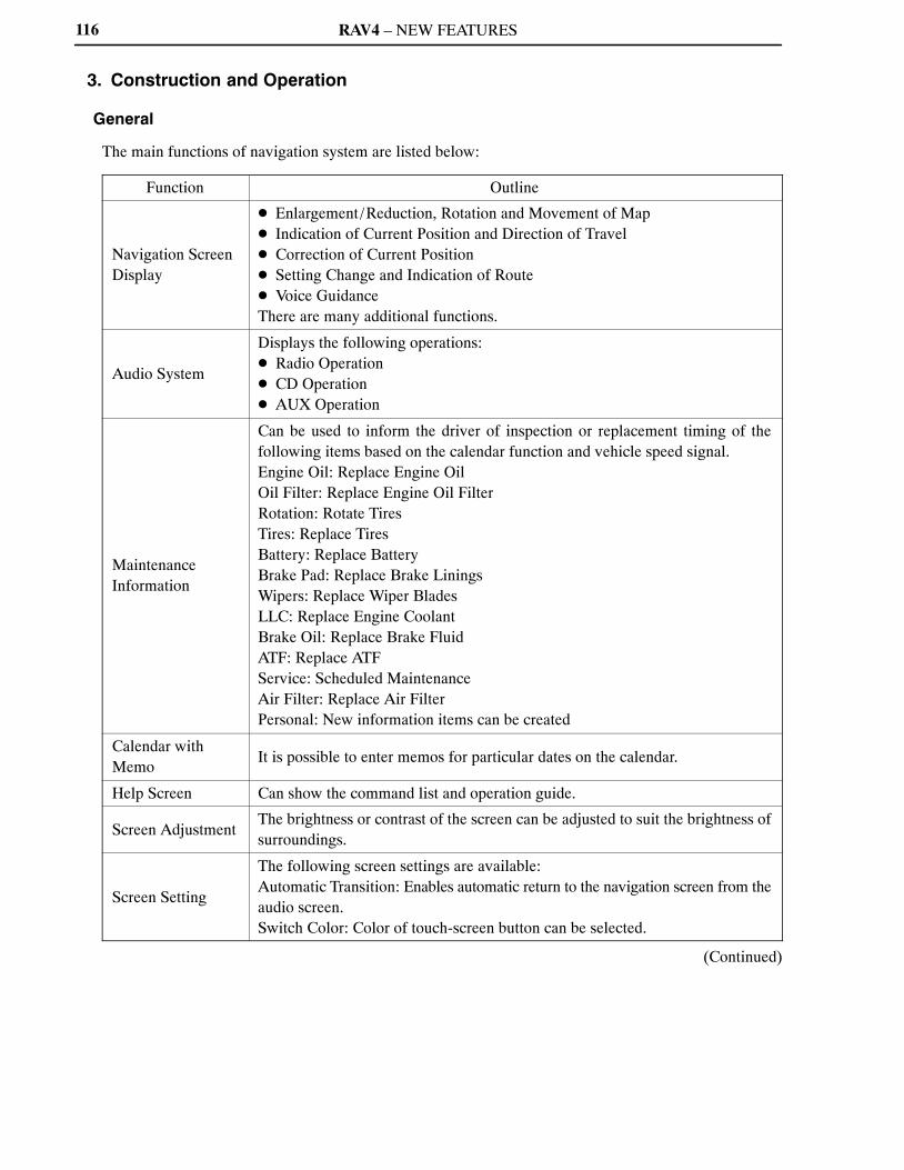
RAV4 – NEW FEATURES116
3. Construction and Operation
General
The main functions of navigation system are listed below:
Function Outline
Navigation ScreenDisplay
� Enlargement/Reduction, Rotation and Movement of Map� Indication of Current Position and Direction of Travel� Correction of Current Position� Setting Change and Indication of Route� Voice GuidanceThere are many additional functions.
Audio System
Displays the following operations:� Radio Operation� CD Operation� AUX Operation
MaintenanceInformation
Can be used to inform the driver of inspection or replacement timing of thefollowing items based on the calendar function and vehicle speed signal.Engine Oil: Replace Engine OilOil Filter: Replace Engine Oil FilterRotation: Rotate TiresTires: Replace TiresBattery: Replace BatteryBrake Pad: Replace Brake LiningsWipers: Replace Wiper BladesLLC: Replace Engine CoolantBrake Oil: Replace Brake FluidATF: Replace ATFService: Scheduled MaintenanceAir Filter: Replace Air FilterPersonal: New information items can be created
Calendar withMemo
It is possible to enter memos for particular dates on the calendar.
Help Screen Can show the command list and operation guide.
Screen AdjustmentThe brightness or contrast of the screen can be adjusted to suit the brightness ofsurroundings.
Screen Setting
The following screen settings are available:Automatic Transition: Enables automatic return to the navigation screen from theaudio screen.Switch Color: Color of touch-screen button can be selected.
(Continued)

RAV4 – NEW FEATURES 117
Function Outline
Delete PersonalData
The following personal data can be deleted or returned to their default settings:� Maintenance Conditions� Maintenance Information “off” Setting� Memory Points� Areas to Avoid� Previous Points� Route Trace� User Selection Settings� Security Code
Beep Setting Beep Sound Off
Select LanguageThe language of the touch-screen buttons, pop-up messages and the voiceguidance can be changed.English, French and Spanish are available.
Diagnosis ScreenDisplay
� Service Check� Display Check� Navigation Check

RAV4 – NEW FEATURES118
Navigation Screen Display
� Based on the map data on the DVD, signals from the GPS satellites, signals from the built-in gyro sensor,and signals from the vehicle speed sensor, the vehicle present position, direction of travel, and drivendistance are calculated and displayed on the navigation screen display.
� The functions of the navigation screen display are shown below:
Item Function
MapDisplay
Linear Touch ScrollEnables smooth scrolling by connecting the touch points on thescreen.
On-route ScrollScrolls the center of the cursor forward and reverse constantly alongthe route.
Heading UpDisplays the map so that the direction of the route progression headsup during route guidance.
Map Color ChangeDepending on the position of the headlight switch, the screenchanges between day mode and night mode.
Front WideDisplays a map in the direction of travel in an enlarged form.(Heading up only)
Stepless Scale DisplayChanges the scale of the map from the basic 13 steps to an even finerdisplay.
Direct Scale Change Directly selects and displays the map scale.
Multi-step Scale Display Changes and displays the map scale in 13 stages.
Split-view Display Displays different modes on a screen that is split into two views.
Points-of-interest Display Displays selected types of marks on the map.
Taillight-interlocked MapColor Change
Changes the displayed color on the map screen when the taillightsare turned ON.
Road Number Sign BoardDisplay Displays the road number on the map.
Compass Mode ScreenDisplays the direction of travel and detailed data of the presentlocation.
Map Coverage InfoScreen Displays the map area that is recorded on DVD.
Street Name Indication onScrolled Map
Displays the street name and the city name even when the map screenis being scrolled.
Foot Print MapDisplays the city maps of Chicago, Detroit, Los Angeles, and NewYork.
Building TenantInformation(for foot print map areas)
Displays information on the tenants in the building.
Arrival Time Displays the expected time of arrival at the destination.
Route Trace Displays the route on the map.
DestinationSearch
Last Destination MemoryStores 20 locations of coordinates, names and times that have beenset as destinations in the past.
Hybrid Points-of-interestSearch
Narrows the search by names of points-of-interest, category, andareas.
Points-of-interestPinpoint Display Pinpoints and displays the position of points-of-interest.
House Number Search Searches for a house number.
Special Memory Point Sets a pre-registered point as a destination point while driving.
Nearest Points-of-interestSearch List Display Searches for nearest points-of-interest and displays a list.
Intersection SearchBy specifying two streets, the point at which they intersect is set asthe destination point.
Emergency Search Performs a specific search for hospitals, police stations and dealers.
(Continued)

RAV4 – NEW FEATURES
08MBE62Y
119
Item Function
Search
Freeway Entrance/Exit Search
Searches for the destination by the name of the street that connectsto a freeway entrance/exit.
Coordinate Search User can input a destination such as an oasis in the desert etc.
Telephone NumberSearch Searches for a facility by its telephone number.
POI, Brand IconIndication Displays icons for points-of-interest.
RouteSearch
Multiple DestinationSetting
Sets multiple destinations. It can also rearrange the sequence of thedestinations.
Route Search Searches for multiple routes.
Search ConditionDesignation Searches for other recommended shortest routes.
Regulated RoadConsideration Performs a search taking regulated roads into consideration.
Avoidance Area Avoids a designated area and searches a route.
Freeway Mode ScreenDisplays information on facilities in the vicinity of the freeway exitsand entrances.
National BorderConscious Search
As far as possible, searches for a route that does not cross the borderbetween the U.S.A. and Canada.
Guidance
Destination DirectionArrow Display
Uses arrows along the road to display the direction of the destinationduring route guidance.
Off-route Arrow DisplayUses arrows to display the direction of the destination duringoff-route.
Rotary GuidanceGuidance that renders the entry and exit into a rotary as a singlebranching point.
Right or Left TurnGuidance Voice guidance to instruct the direction of travel to be taken.
Freeway Direction ofTravel Guidance
Voice guidance to instruct the direction of travel to take on thefreeway.
Distance DisplayDestination Displays the distance from the present location to the destination.
Freeway Branch TypeSpecimen Guidance Type specimen for guidance to a freeway branch.
Intersection Zoom-inDisplay Zoom-in display when approaching an intersection.
Turn List Display Displays a turn list on the right side of the two-screen display.
Calendar Anniversary or appointment dates can be input and displayed.
Function HelpExplains the functions of the switches on the main screens, such asthe destination and menu.
Diagnosis Screen Display
The navigation system is equipped with a self-diagnosisfunction and can display the diagnosis menus shown onthe right.The diagnosis menu contains the following items:
a) Service Checkb) Display Checkc) Navigation Check
For details on the procedure required to enter thediagnosis menu screen, refer to the 2009 RAV4 RepairManual (Pub. No. RM10S0U).
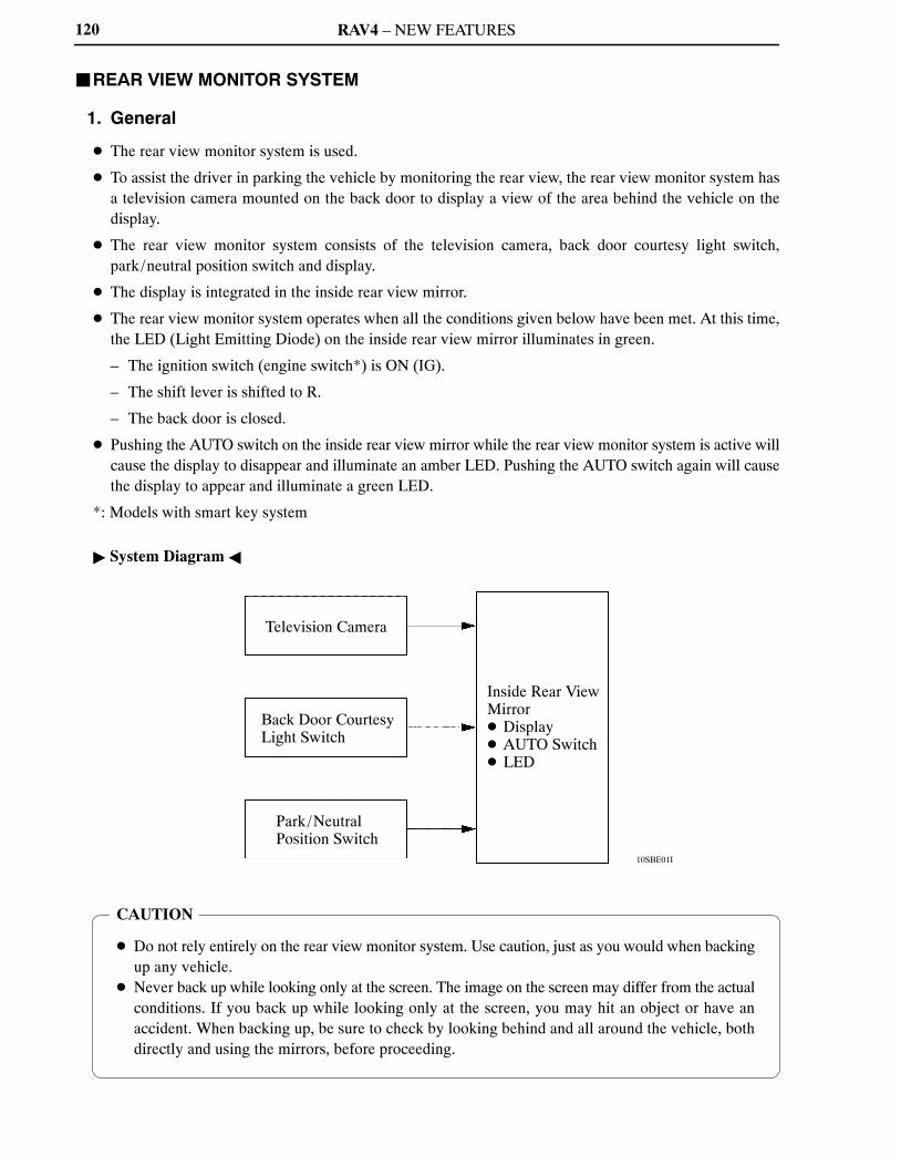
RAV4 – NEW FEATURES
10SBE01I
Television Camera
Park/NeutralPosition Switch
Inside Rear ViewMirror� Display� AUTO Switch� LED
Back Door CourtesyLight Switch
CAUTION
� Do not rely entirely on the rear view monitor system. Use caution, just as you would when backingup any vehicle.
� Never back up while looking only at the screen. The image on the screen may differ from the actualconditions. If you back up while looking only at the screen, you may hit an object or have anaccident. When backing up, be sure to check by looking behind and all around the vehicle, bothdirectly and using the mirrors, before proceeding.
120
�REAR VIEW MONITOR SYSTEM
1. General
� The rear view monitor system is used.
� To assist the driver in parking the vehicle by monitoring the rear view, the rear view monitor system hasa television camera mounted on the back door to display a view of the area behind the vehicle on thedisplay.
� The rear view monitor system consists of the television camera, back door courtesy light switch,park/neutral position switch and display.
� The display is integrated in the inside rear view mirror.
� The rear view monitor system operates when all the conditions given below have been met. At this time,the LED (Light Emitting Diode) on the inside rear view mirror illuminates in green.
– The ignition switch (engine switch*) is ON (IG).
– The shift lever is shifted to R.
– The back door is closed.
� Pushing the AUTO switch on the inside rear view mirror while the rear view monitor system is active willcause the display to disappear and illuminate an amber LED. Pushing the AUTO switch again will causethe display to appear and illuminate a green LED.
*: Models with smart key system
� System Diagram �

RAV4 – NEW FEATURES
10SBE14Y
Inside Rear View Mirror
Display
AUTO Switch
LED
Television Camera
Park/Neutral Position Switch
Back Door CourtesyLight Switch
Models with Tyre Carrier
Television Camera
Back Door CourtesyLight Switch
Models without Tyre Carrier
121
2. Layout of Main Components
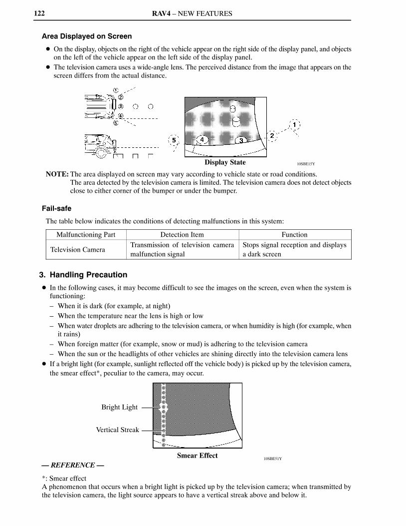
RAV4 – NEW FEATURES
10SBE15YDisplay State
10SBE51Y
Bright Light
Smear Effect
Vertical Streak
122
Area Displayed on Screen
� On the display, objects on the right of the vehicle appear on the right side of the display panel, and objectson the left of the vehicle appear on the left side of the display panel.
� The television camera uses a wide-angle lens. The perceived distance from the image that appears on thescreen differs from the actual distance.
NOTE: The area displayed on screen may vary according to vehicle state or road conditions.The area detected by the television camera is limited. The television camera does not detect objectsclose to either corner of the bumper or under the bumper.
Fail-safe
The table below indicates the conditions of detecting malfunctions in this system:
Malfunctioning Part Detection Item Function
Television CameraTransmission of television cameramalfunction signal
Stops signal reception and displaysa dark screen
3. Handling Precaution
� In the following cases, it may become difficult to see the images on the screen, even when the system isfunctioning:– When it is dark (for example, at night)– When the temperature near the lens is high or low– When water droplets are adhering to the television camera, or when humidity is high (for example, when
it rains)– When foreign matter (for example, snow or mud) is adhering to the television camera– When the sun or the headlights of other vehicles are shining directly into the television camera lens
� If a bright light (for example, sunlight reflected off the vehicle body) is picked up by the television camera,the smear effect*, peculiar to the camera, may occur.
— REFERENCE —
*: Smear effectA phenomenon that occurs when a bright light is picked up by the television camera; when transmitted bythe television camera, the light source appears to have a vertical streak above and below it.

RAV4 – NEW FEATURES
01NBE18Y
UnlockOperation
LockOperation
Entry Unlock/Entry Lock Functions Start Function
123
�SMART KEY SYSTEM
1. General
� The smart key system is used.
� The smart key system has a wireless door lock control function and an engine immobilizer function.Furthermore, in this system, the following functions (entry function and start function) are also possiblesimply by carrying the key in the driver’s possession without using a key or transmitter button.
– All the doors and back door unlock/lock. (Entry unlock/entry lock functions)
– Engine starts simply by pressing the engine switch while depressing the brake pedal. (Start function)
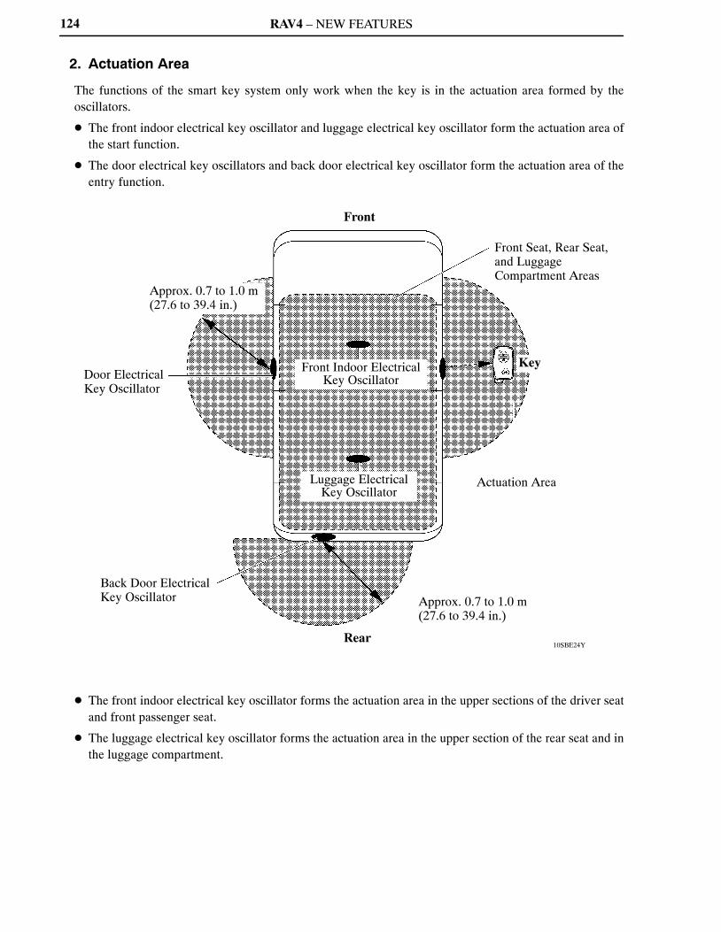
RAV4 – NEW FEATURES
10SBE24Y
Front
Approx. 0.7 to 1.0 m(27.6 to 39.4 in.)
Door ElectricalKey Oscillator
Back Door ElectricalKey Oscillator
Front Indoor ElectricalKey Oscillator
Luggage ElectricalKey Oscillator
Rear
Front Seat, Rear Seat,and LuggageCompartment Areas
Key
Actuation Area
Approx. 0.7 to 1.0 m(27.6 to 39.4 in.)
124
2. Actuation Area
The functions of the smart key system only work when the key is in the actuation area formed by theoscillators.
� The front indoor electrical key oscillator and luggage electrical key oscillator form the actuation area ofthe start function.
� The door electrical key oscillators and back door electrical key oscillator form the actuation area of theentry function.
� The front indoor electrical key oscillator forms the actuation area in the upper sections of the driver seatand front passenger seat.
� The luggage electrical key oscillator forms the actuation area in the upper section of the rear seat and inthe luggage compartment.
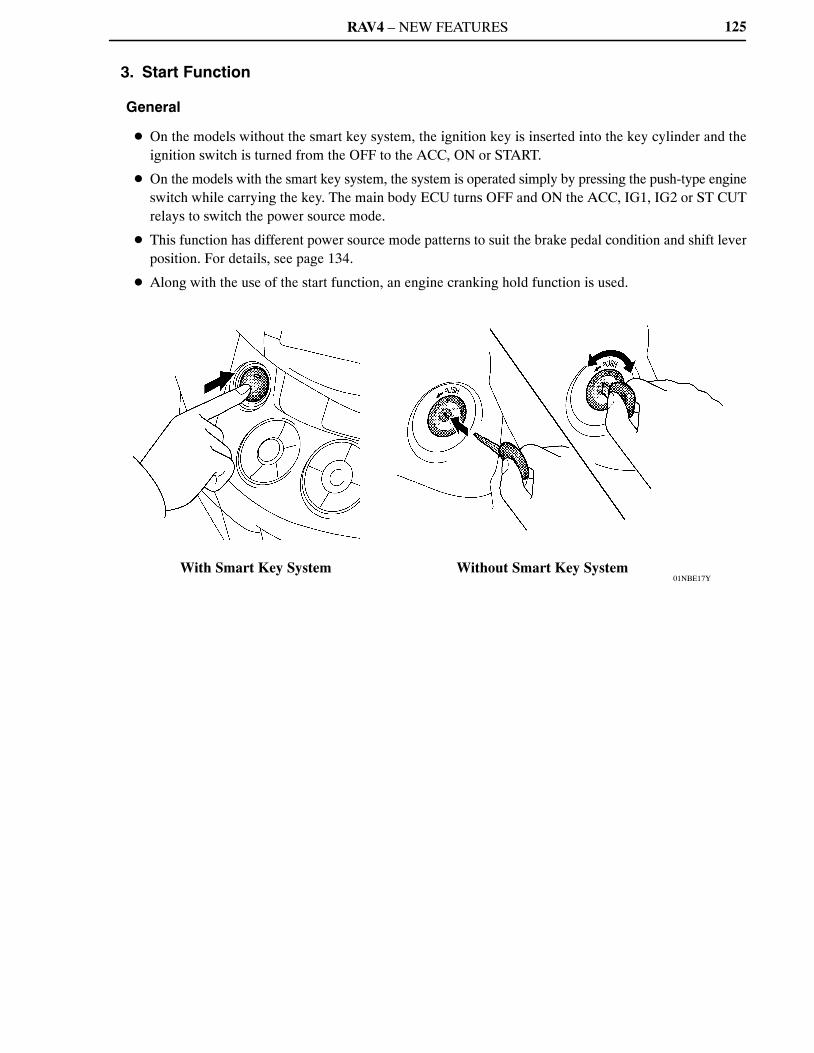
RAV4 – NEW FEATURES
01NBE17YWith Smart Key System Without Smart Key System
125
3. Start Function
General
� On the models without the smart key system, the ignition key is inserted into the key cylinder and theignition switch is turned from the OFF to the ACC, ON or START.
� On the models with the smart key system, the system is operated simply by pressing the push-type engineswitch while carrying the key. The main body ECU turns OFF and ON the ACC, IG1, IG2 or ST CUTrelays to switch the power source mode.
� This function has different power source mode patterns to suit the brake pedal condition and shift leverposition. For details, see page 134.
� Along with the use of the start function, an engine cranking hold function is used.

RAV4 – NEW FEATURES
285BE62
EngineSwitch Main Body
ECU(InstrumentPanel JunctionBlock)
ACC Relay
IG1 Relay
IG2 Relay
ST CUT Relay
ST Relay
With Smart Key System
Ignition Key Cylinder� Ignition Switch
To Each System
IG1 Relay
IG2 Relay
ST Relay
Without Smart Key System
126
Major Difference
The major differences between the start function and conventional ignition key function are as follows:
FunctionStart (Push Button) Conventional Ignition Key
Item
Switch Engine Switch Ignition Switch
Key Cylinder — Ignition Key Cylinder
KeyWith a built-in transmitter for thesmart key system
� With a built-in transponder chip for theengine immobilizer system
� With a built-in transmitter for the wirelessdoor lock control system
RelayFive Relays(ACC, IG1, IG2, ST CUT and STRelays)
Three Relays(IG1, IG2, and ST Relays)
Power RelayControl
Main Body ECU Contact Type Ignition Switch
Security
Restricts the operation of the engineswitch unless the certification ECUrecognizes the ID code of the key.
Restricts the starting of the engine unless thetransponder key ECU recognizes the ID codeof the key.
Restricts the unlocking of thesteering lock unless the steering lockECU receives permissive signalsfrom the certification ECU.
A steering lock mechanism mechanicallyrestricts the movement of the steering inunison with the movement of the key cylinder.
� Power Source Circuit �

RAV4 – NEW FEATURES
10SBE25Y
Engine Switch� Transponder Key Amplifier
ID Code Signal*Engine SwitchPosition Signal
Stop Light Switch
Combination Meter� Vehicle Speed Signal
Main Body ECU(InstrumentPanelJunctionBlock)
ACC Relay
IG1 Relay
IG2 Relay
ST CUT Relay ST RelaySteering Lock ECU
LIN CAN(MS Bus)
ImmobilizerCode ECU
ECM Park/Neutral Position Switch
CAN(V Bus)
DLC3
CertificationECU
Front IndoorElectrical KeyOscillator
LuggageElectrical KeyOscillator
Door ControlReceiver
Key
127
System Diagram
The main body ECU controls the start function. The system diagram below shows the components of thefunction:
*: Only when the key battery is low.

RAV4 – NEW FEATURES
10SBE27Y
10SBE26Y
Key
Certification ECU
ImmobilizerCode ECU
Steering Lock ECU
Engine Switch� Transponder Key Amplifier
Main Body ECU(Instrument Panel Junction Block)
Stop Light Switch
Park/Neutral Position Switch
ECM
Front Indoor Electrical Key Oscillator
Luggage Electrical Key Oscillator
Door Control Receiver
128
Layout of Main Components

RAV4 – NEW FEATURES 129
Function of Main Components
Component Function
Engine Switch� Transponder Key
Amplifier
� Transmits the engine switch signal to the main body ECU.� Informs the driver of a power source mode or system abnormality using
the indicator light.� Receives the ID code and transmits it to the certification ECU when the
key battery is low.
KeyReceives the signals from oscillators and returns the ID code to the doorcontrol receiver.
Front Indoor/LuggageElectrical Key Oscillator
Receives a request signal from the certification ECU and forms theactuation area in the cabin.
Door Control Receiver Receives the ID code from the key and transmits it to the certification ECU.
Main Body ECU
� Switches the power source modes in four modes (OFF, ON [ACC], ON[IG], START) in accordance with the shift position and the state of thestop light switch.
� Controls the start function in accordance with the signals received fromthe switches and each ECU.
Certification ECUCertifies the ID code received from the door control receiver and transmitsthe certification results to the immobilizer code ECU and steering lockECU.
Stop Light Switch Outputs the state of the brake pedal to the main body ECU.
Immobilizer Code ECUReceives the steering unlock or engine immobilizer unset request signalfrom the certification ECU, certifies them, and transmits each unset signalto the steering lock ECU or ECM.
ECM
� Receives the engine start request signal from the main body ECU, turnson the ST relay, and starts the engine.
� Receives the signal from the immobilizer code ECU and performs engineignition and injection.
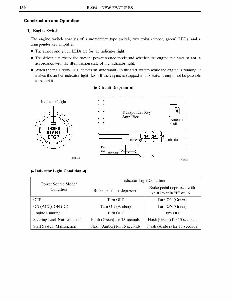
RAV4 – NEW FEATURES
285BE66263BE05
Indicator Light
Transponder KeyAmplifier
AntennaCoil
Indicator Illumination
Free
Full Traveling
� Circuit Diagram �
130
Construction and Operation
1) Engine Switch
The engine switch consists of a momentary type switch, two color (amber, green) LEDs, and atransponder key amplifier.
� The amber and green LEDs are for the indicator light.
� The driver can check the present power source mode and whether the engine can start or not inaccordance with the illumination state of the indicator light.
� When the main body ECU detects an abnormality in the start system while the engine is running, itmakes the amber indicator light flash. If the engine is stopped in this state, it might not be possibleto restart it.
� Indicator Light Condition �
Power Source Mode/Condition
Indicator Light Condition
Brake pedal not depressedBrake pedal depressed with
shift lever in “P” or “N”
OFF Turn OFF Turn ON (Green)
ON (ACC), ON (IG) Turn ON (Amber) Turn ON (Green)
Engine Running Turn OFF Turn OFF
Steering Lock Not Unlocked Flash (Green) for 15 seconds Flash (Green) for 15 seconds
Start System Malfunction Flash (Amber) for 15 seconds Flash (Amber) for 15 seconds

RAV4 – NEW FEATURES
263BE138
Main Body ECU(Instrument Panel Junction Block)
IG1 RelayActuation Circuit
CPU
Hold
HoldCancel
Hold Circuit
IG2 Relay Actuation Circuit
IG1 Relay
IG2 Relay
Service Tip
The main body ECU constantly stores the present power source mode in its memory. Therefore,if the power to the main body ECU is interrupted due to the removal of the battery, the main bodyECU restores the power source mode after the battery is reconnected.For this reason, if the battery is removed when the power source mode is anything other than OFF,the power source mode will be restored to the vehicle at the same time the power source modeis restored to the main body ECU (by reconnecting the battery).Therefore, before removing or disconnecting the battery, make sure to set the power source modeto OFF.
131
2) Main Body ECU
The main body ECU consists of the IG1 and IG2 relay actuation circuits, CPU, and hold circuit.
� The hold circuit is installed to prevent the power supply to the relays from being cut off when anabnormality occurs in the IG1 and/or IG2 relay actuation circuits during driving.
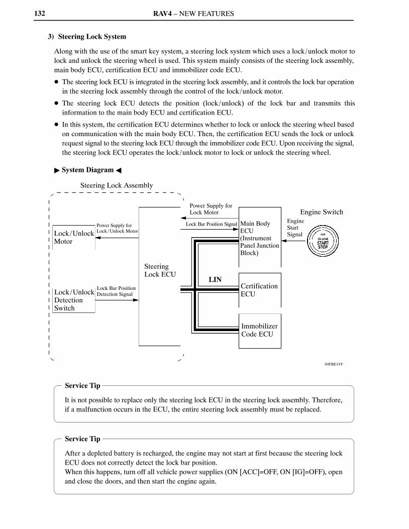
RAV4 – NEW FEATURES
04FBE14Y
Steering Lock Assembly
Lock/UnlockMotor
Power Supply forLock / Unlock Motor
Lock/UnlockDetection Switch
Lock Bar PositionDetection Signal
SteeringLock ECU
Power Supply forLock Motor
Lock Bar Position Signal
LIN
Main BodyECU(InstrumentPanel JunctionBlock)
CertificationECU
ImmobilizerCode ECU
EngineStartSignal
Engine Switch
Service Tip
It is not possible to replace only the steering lock ECU in the steering lock assembly. Therefore,if a malfunction occurs in the ECU, the entire steering lock assembly must be replaced.
Service Tip
After a depleted battery is recharged, the engine may not start at first because the steering lockECU does not correctly detect the lock bar position.When this happens, turn off all vehicle power supplies (ON [ACC]=OFF, ON [IG]=OFF), openand close the doors, and then start the engine again.
132
3) Steering Lock System
Along with the use of the smart key system, a steering lock system which uses a lock/unlock motor tolock and unlock the steering wheel is used. This system mainly consists of the steering lock assembly,main body ECU, certification ECU and immobilizer code ECU.
� The steering lock ECU is integrated in the steering lock assembly, and it controls the lock bar operationin the steering lock assembly through the control of the lock/unlock motor.
� The steering lock ECU detects the position (lock/unlock) of the lock bar and transmits thisinformation to the main body ECU and certification ECU.
� In this system, the certification ECU determines whether to lock or unlock the steering wheel basedon communication with the main body ECU. Then, the certification ECU sends the lock or unlockrequest signal to the steering lock ECU through the immobilizer code ECU. Upon receiving the signal,the steering lock ECU operates the lock/unlock motor to lock or unlock the steering wheel.
� System Diagram �

RAV4 – NEW FEATURES 133
Start Function Operation
1) General
� When the driver enters the vehicle with the key carried in the driver’s possession and the certificationECU recognizes the ID code of the key, the main body ECU authorizes the operation of the engineswitch. As a result, the power source mode changes to the mode selected by the engine switch.
� The start function has different power source mode patterns to suit the brake pedal condition and shiftlever position.
Pattern Brake Pedal Shift Lever Power Source Mode Pattern
A[See page 135]
Depressed P or N PositionWhen the engine switch is pushed once.� OFF � START
B[See page 138] Not
Depressed
P PositionEach time the engine switch is pushed.� OFF � ON (ACC) � ON (IG) � OFF
C[See page 140]
ExceptP Position
Each time the engine switch is pushed.� OFF � ON (ACC) � ON (IG) � ON (ACC)
D[See page 140]
—Except
P Position
When the engine switch is pushed in the ON(IG) or START.� ON (IG) or START � ON (ACC)
E[See page 140]
— P PositionWhen the engine switch is pushed in the ON(IG) or START.� ON (IG) or START � OFF
� After approximately 1 hour has elapsed with the power source mode in ON (ACC), the power sourcecontrol ECU will automatically turn off the power.
� When the key battery is low, the start function can be made to operate by holding the TOYOTA markof the key against the engine switch. For details, see page 141.
� The table on the next page shows the transition of the power source modes.

RAV4 – NEW FEATURES
01NBE04Y
PowerSourceMode
OFF
ON (ACC)
ON (IG)
START
P Position
EngineSwitchPushed
Engine SwitchPushed withBrake PedalDepressed
After1 hour
N Position
EngineSwitchPushed
Engine SwitchPushed withBrake PedalDepressed
Except P and N Positions
EngineSwitchPushed
Engine SwitchPushed withBrake PedalDepressed
: Transition
: Only when the key certification has been approved
: Only when the vehicle is stopped
134
� Transition of Power Source Mode �
NOTE:
� Normally, the operation of the engine switch is disabled while the vehicle is being driven. However,if the engine must be stopped in an emergency while the vehicle is in motion, the driver can press theengine switch for approximately 3 seconds or more to stop the engine.
� If no signals are transmitted to the main body ECU due to a malfunction in the stop light switch system,the engine will not start even if the driver presses the engine switch while depressing the brake pedal.In this case, the driver can start the engine by the following operations:1) Press the engine switch to turn the power source mode from OFF to ON (ACC), and 2) press theengine switch again and hold it for 15 seconds or more.
� Above two operations must be applied only in emergency situations. Under normal conditions, theengine must not be stopped by pressing the engine switch during driving or started without depressingthe brake pedal when the shift lever is in any position other than P or N.

RAV4 – NEW FEATURES
10SBE28Y
Stop Light Switch
b)
b)
d)
Main Body ECU(InstrumentPanel JunctionBlock)
h)
CAN (V Bus)
ACC Relay
g)
b)
Door ControlReceiver
f)
e)
Key
c)
c)
LIN
c) c)
Front Indoor/Luggage ElectricalKey Oscillators
Park/Neutral Position Switch
b)
ECMCertificationECU
135
2) Pattern A: OFF � START
Step System Operation
a) The driver enters the vehicle with the key carried in the driver’s possession.
b)
When the driver presses the engine switch once with the following conditions satisfied, themain body ECU recognizes the engine switch signal and transmits the key certificationrequest signal to the certification ECU.� Shift position is “P” or “N”.� Brake pedal is depressed.� Power source mode is in “OFF”.
c)The certification ECU receives the key certification request signal and transmits a requestsignal to the front indoor/luggage electrical key oscillators. These oscillators then transmitthe request signal.
d) The main body ECU turns on the green indicator light of the engine switch.
e)The moment the key receives the request signal, it returns to the door control receiver an IDcode that includes the response code.
f) The door control receiver receives this code and transmits it to the certification ECU.
g)The certification ECU judges and certifies the ID code, and transmits a key certification OKsignal to the main body ECU.
h) After receiving the key certification OK signal, the main body ECU turns on the ACC relay.
(Continued)
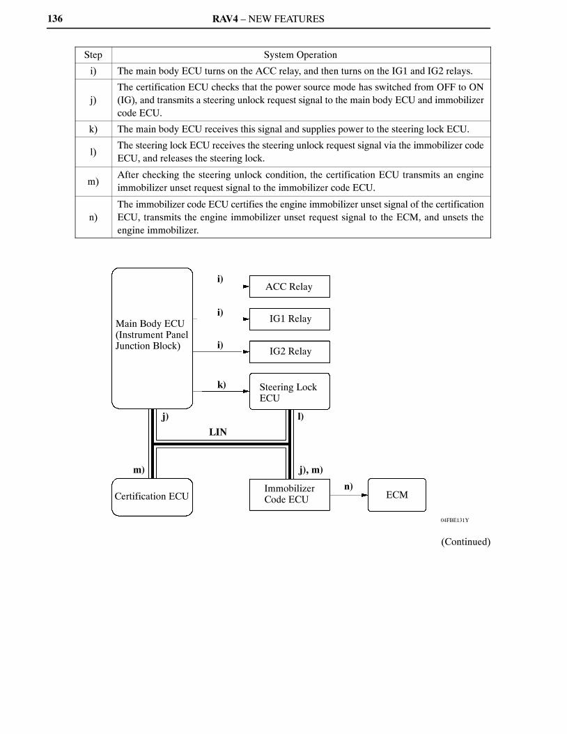
RAV4 – NEW FEATURES
04FBE131Y
Main Body ECU(Instrument PanelJunction Block) i)
i)
i)
k)
ACC Relay
IG1 Relay
IG2 Relay
Steering LockECU
j)
m)
Certification ECU
LIN
l)
j), m)
ImmobilizerCode ECU
n)ECM
136
Step System Operation
i) The main body ECU turns on the ACC relay, and then turns on the IG1 and IG2 relays.
j)The certification ECU checks that the power source mode has switched from OFF to ON(IG), and transmits a steering unlock request signal to the main body ECU and immobilizercode ECU.
k) The main body ECU receives this signal and supplies power to the steering lock ECU.
l)The steering lock ECU receives the steering unlock request signal via the immobilizer codeECU, and releases the steering lock.
m)After checking the steering unlock condition, the certification ECU transmits an engineimmobilizer unset request signal to the immobilizer code ECU.
n)The immobilizer code ECU certifies the engine immobilizer unset signal of the certificationECU, transmits the engine immobilizer unset request signal to the ECM, and unsets theengine immobilizer.
(Continued)

RAV4 – NEW FEATURES
04FBE136Y
Engine Switch
s)Main Body ECU(Instrument PanelJunction Block)
Crankshaft Position Sensor(Engine Speed Signal)
r)
o)r)
q)
p), r)ST CUT Relay
Park /NeutralPosition Switch
ST Relay
StarterSteering LockECU
LIN
o)
ECU
137
Step System Operation
o)After checking that the steering is in the unlock condition, the main body ECU transmits astarter request (STSW) signal to the ECM.
p) The ECM outputs an ST relay (STAR) signal, and actuates the starter.
q)If the ST relay (STAR) signal cannot be output because the power supplied to the ECM islow, the main body ECU outputs the ST relay (STAR) signal instead, to help actuate thestarter.
r)When the ECM judges from the engine speed signal that engine start has been completed,it stops the ST relay (STAR) signal, and stops the starter.
s)The main body ECU checks that the engine start has been completed, and turns off theindicator light of the engine switch.
RAV4 – NEW FEATURES138
3) Pattern B: OFF � ON (ACC) � ON (IG) � OFF
a. OFF � ON (ACC)
Step System Operation
a) The driver enters the vehicle with the key carried in the driver’s possession.
b)
When the driver presses the engine switch once with the following conditions satisfied, themain body ECU recognizes the engine switch signal and transmits the key certificationrequest signal to the certification ECU.� Shift position is “P” or “N”.� Brake pedal is not depressed.� Power source mode is in “OFF”.
c)When the brake pedal is not depressed, the main body ECU turns on the amber indicator lightof the engine switch.
d)The subsequent system operation is the same as d) to h) in pattern “A”. For details, see page135.
b. ON (ACC) � ON (IG)
Step System Operation
a)When the power source mode is “ON (ACC)” and the driver presses the engine switch again,the main body ECU recognizes the engine switch signal and turns on the IG1 and IG2 relays.
b)The subsequent system operation is the same as j) to n) in pattern “A”. For details, see page135.
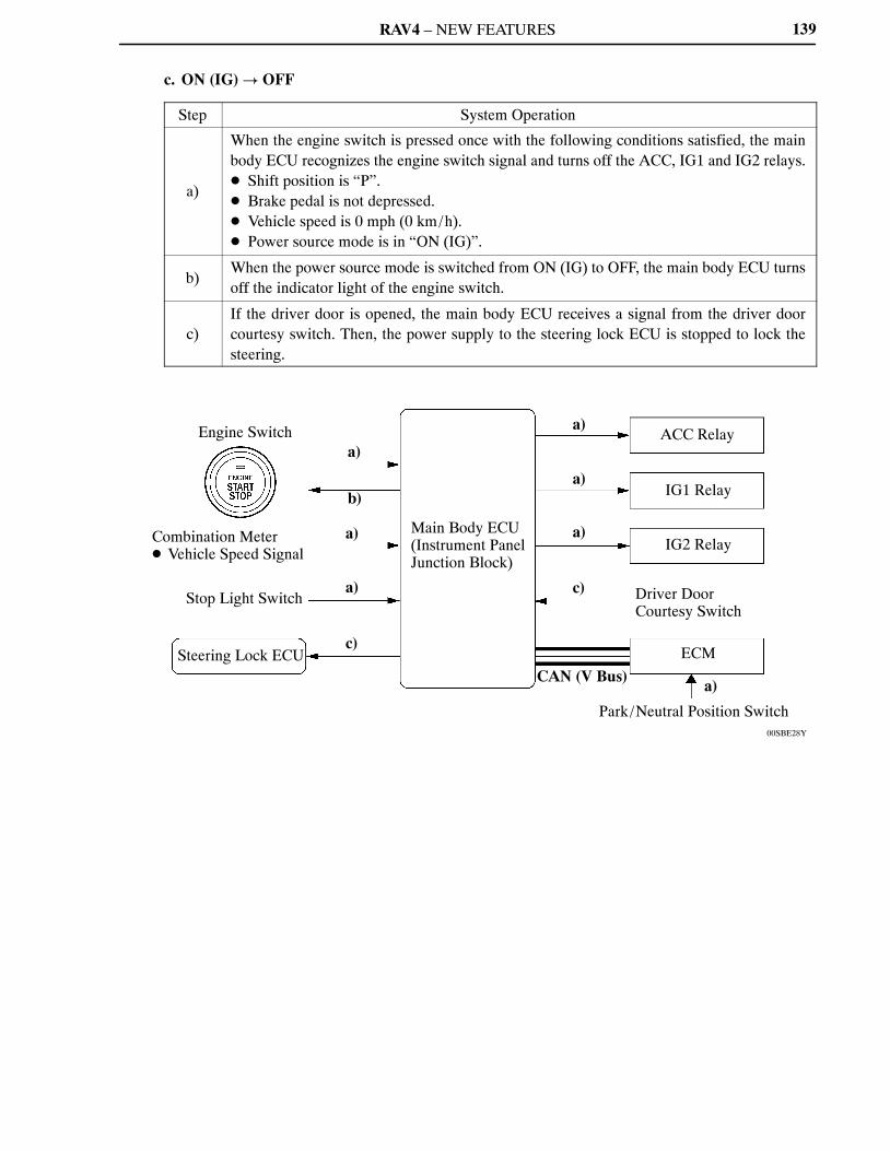
RAV4 – NEW FEATURES
00SBE28Y
Engine Switch
Combination Meter� Vehicle Speed Signal
Stop Light Switch
Steering Lock ECU
a)
b)
a)
a)
c)
Main Body ECU(Instrument PanelJunction Block)
a)
a)
a)
c)
CAN (V Bus)
ACC Relay
IG1 Relay
IG2 Relay
Driver DoorCourtesy Switch
ECM
a)
Park/Neutral Position Switch
139
c. ON (IG) � OFF
Step System Operation
a)
When the engine switch is pressed once with the following conditions satisfied, the mainbody ECU recognizes the engine switch signal and turns off the ACC, IG1 and IG2 relays.� Shift position is “P”.� Brake pedal is not depressed.� Vehicle speed is 0 mph (0 km/h).� Power source mode is in “ON (IG)”.
b)When the power source mode is switched from ON (IG) to OFF, the main body ECU turnsoff the indicator light of the engine switch.
c)If the driver door is opened, the main body ECU receives a signal from the driver doorcourtesy switch. Then, the power supply to the steering lock ECU is stopped to lock thesteering.
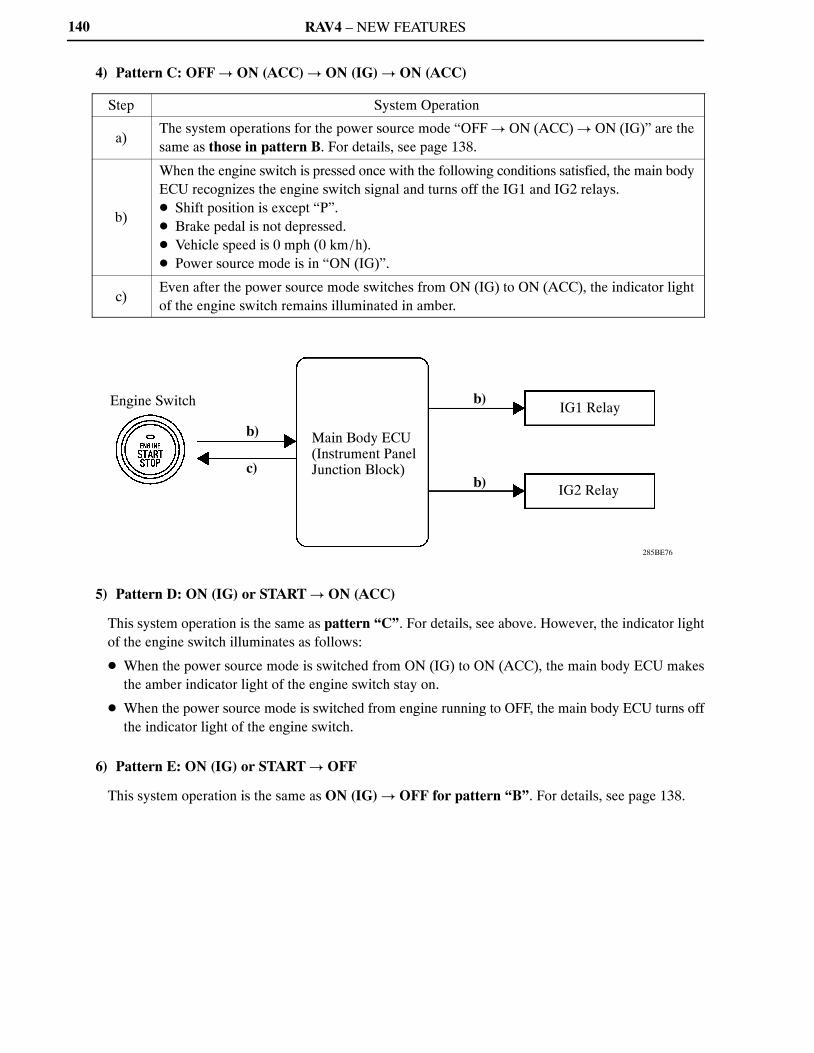
RAV4 – NEW FEATURES
285BE76
Engine Switch
b)
c)
Main Body ECU(Instrument Panel Junction Block)
b)
b)
IG1 Relay
IG2 Relay
140
4) Pattern C: OFF � ON (ACC) � ON (IG) � ON (ACC)
Step System Operation
a)The system operations for the power source mode “OFF � ON (ACC) � ON (IG)” are thesame as those in pattern B. For details, see page 138.
b)
When the engine switch is pressed once with the following conditions satisfied, the main bodyECU recognizes the engine switch signal and turns off the IG1 and IG2 relays.� Shift position is except “P”.� Brake pedal is not depressed.� Vehicle speed is 0 mph (0 km/h).� Power source mode is in “ON (IG)”.
c)Even after the power source mode switches from ON (IG) to ON (ACC), the indicator lightof the engine switch remains illuminated in amber.
5) Pattern D: ON (IG) or START � ON (ACC)
This system operation is the same as pattern “C”. For details, see above. However, the indicator lightof the engine switch illuminates as follows:
� When the power source mode is switched from ON (IG) to ON (ACC), the main body ECU makesthe amber indicator light of the engine switch stay on.
� When the power source mode is switched from engine running to OFF, the main body ECU turns offthe indicator light of the engine switch.
6) Pattern E: ON (IG) or START � OFF
This system operation is the same as ON (IG) � OFF for pattern “B”. For details, see page 138.
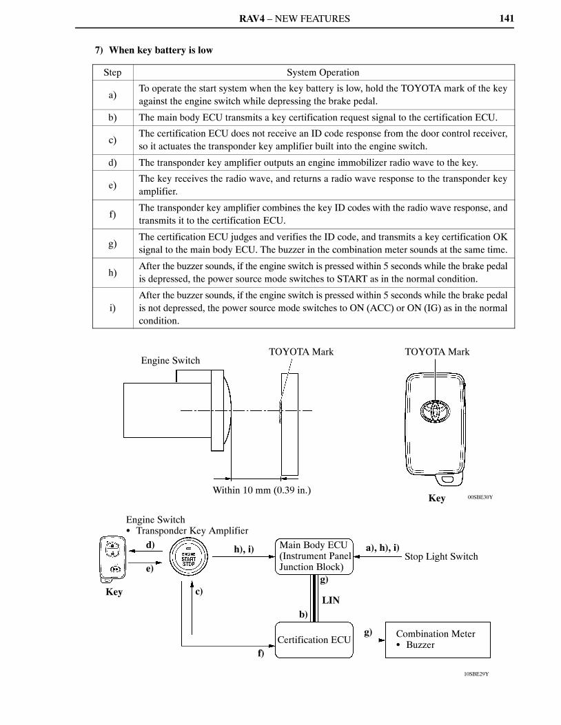
RAV4 – NEW FEATURES
00SBE30Y
10SBE29Y
Engine SwitchTOYOTA Mark
Within 10 mm (0.39 in.)
TOYOTA Mark
Key
Key
Engine Switch� Transponder Key Amplifier
d)
e)
h), i)
c)
f)
Main Body ECU(Instrument Panel Junction Block)
a), h), i)Stop Light Switch
g)
LINb)
Certification ECUg) Combination Meter
� Buzzer
141
7) When key battery is low
Step System Operation
a)To operate the start system when the key battery is low, hold the TOYOTA mark of the keyagainst the engine switch while depressing the brake pedal.
b) The main body ECU transmits a key certification request signal to the certification ECU.
c)The certification ECU does not receive an ID code response from the door control receiver,so it actuates the transponder key amplifier built into the engine switch.
d) The transponder key amplifier outputs an engine immobilizer radio wave to the key.
e)The key receives the radio wave, and returns a radio wave response to the transponder keyamplifier.
f)The transponder key amplifier combines the key ID codes with the radio wave response, andtransmits it to the certification ECU.
g)The certification ECU judges and verifies the ID code, and transmits a key certification OKsignal to the main body ECU. The buzzer in the combination meter sounds at the same time.
h)After the buzzer sounds, if the engine switch is pressed within 5 seconds while the brake pedalis depressed, the power source mode switches to START as in the normal condition.
i)After the buzzer sounds, if the engine switch is pressed within 5 seconds while the brake pedalis not depressed, the power source mode switches to ON (ACC) or ON (IG) as in the normalcondition.

RAV4 – NEW FEATURES142
Diagnosis
The main body ECU can detect malfunctions in the start function when the power source mode is ON (IG).When the ECU detects a malfunction, the amber indicator light of the engine switch flashes to warn thedriver. At the same time, the ECU stores the 5-digit DTC (Diagnostic Trouble Code) in the memory.
� The indicator light warning continues for 15 seconds even when the power source mode is switched toOFF.
� The DTC can be read by connecting a Techstream to the DLC3.
� The start function cannot be operated again if a malfunction occurs.
For details, refer to the RAV4 Repair Manual (Pub. No. RM10S0U).
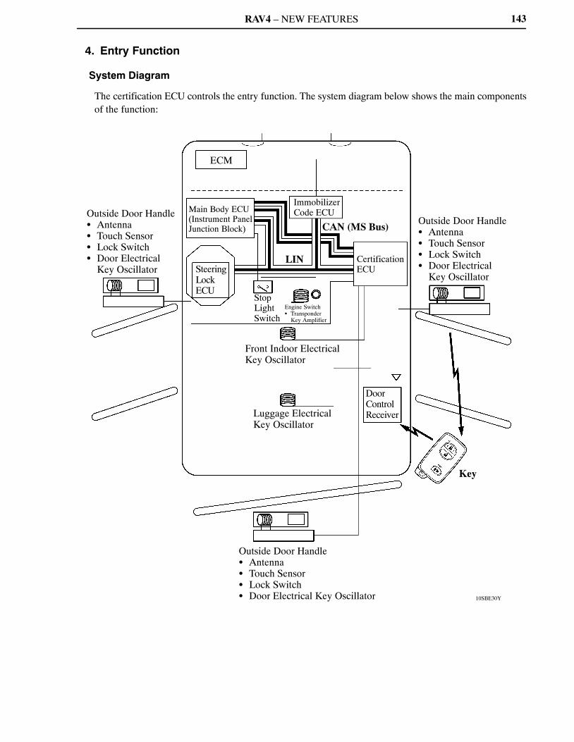
RAV4 – NEW FEATURES
10SBE30Y
Outside Door Handle� Antenna� Touch Sensor� Lock Switch� Door Electrical
Key Oscillator
Main Body ECU(Instrument Panel Junction Block)
ECM
Immobilizer Code ECU
CAN (MS Bus)
Steering Lock ECU
LIN
StopLightSwitch
Engine Switch� Transponder
Key Amplifier
Certification ECU
Front Indoor Electrical Key Oscillator
Luggage Electrical Key Oscillator
DoorControl Receiver
Outside Door Handle� Antenna� Touch Sensor� Lock Switch� Door Electrical
Key Oscillator
Key
Outside Door Handle� Antenna� Touch Sensor� Lock Switch� Door Electrical Key Oscillator
143
4. Entry Function
System Diagram
The certification ECU controls the entry function. The system diagram below shows the main componentsof the function:
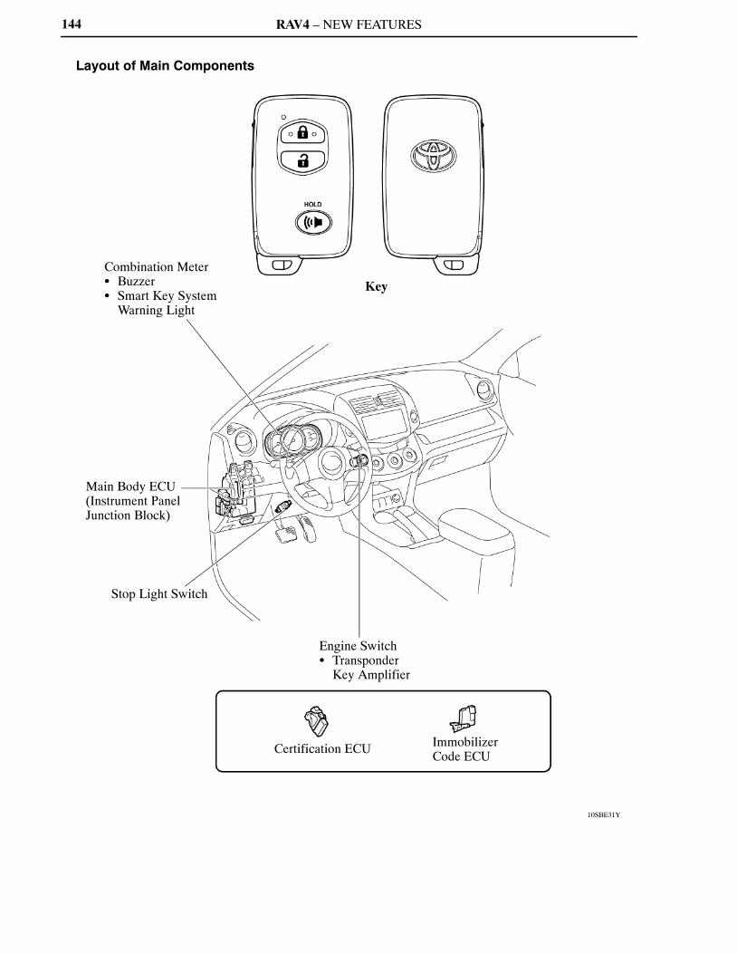
RAV4 – NEW FEATURES
10SBE31Y
Key
Combination Meter� Buzzer� Smart Key System
Warning Light
Main Body ECU(Instrument Panel Junction Block)
Stop Light Switch
Engine Switch� Transponder
Key Amplifier
Certification ECU Immobilizer Code ECU
144
Layout of Main Components
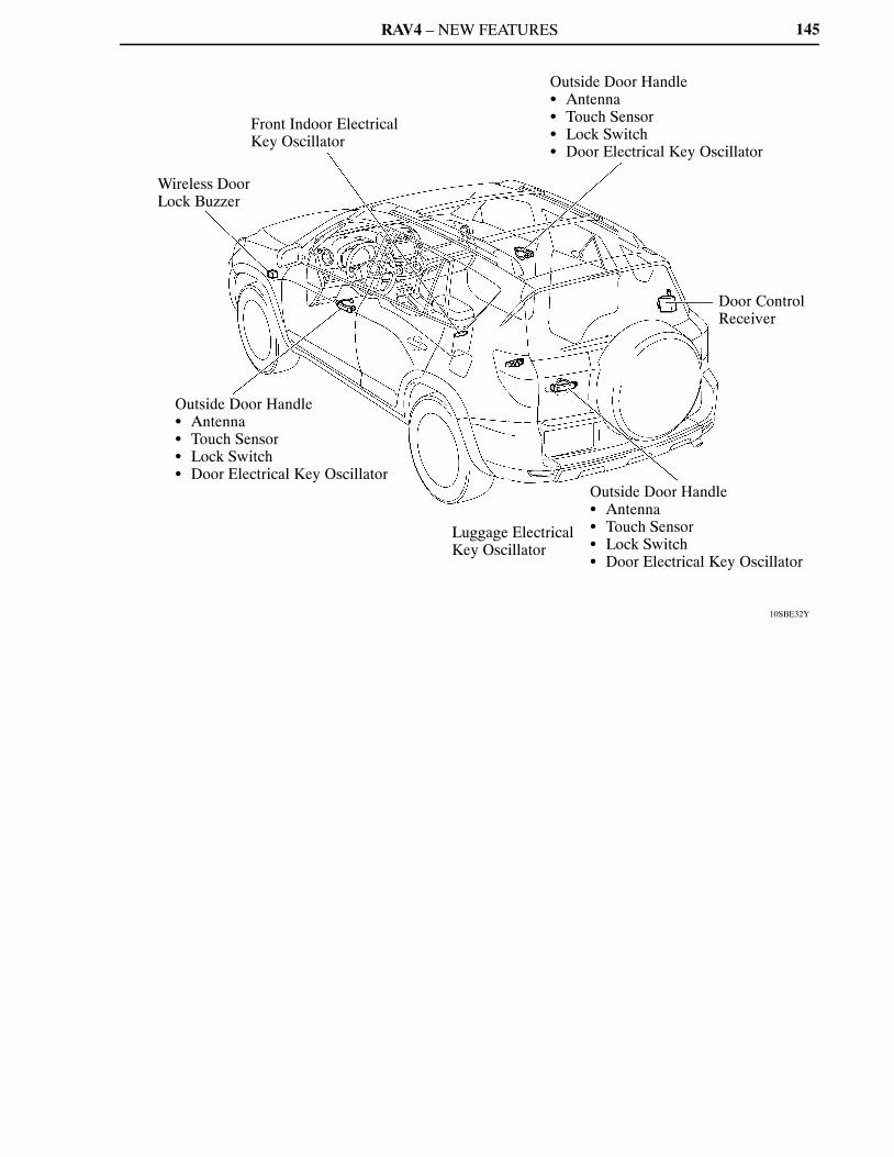
RAV4 – NEW FEATURES
10SBE32Y
Front Indoor Electrical Key Oscillator
Wireless Door Lock Buzzer
Outside Door Handle� Antenna� Touch Sensor� Lock Switch� Door Electrical Key Oscillator
Outside Door Handle� Antenna� Touch Sensor� Lock Switch� Door Electrical Key Oscillator
Door Control Receiver
Outside Door Handle� Antenna� Touch Sensor� Lock Switch� Door Electrical Key Oscillator
Luggage Electrical Key Oscillator
145

RAV4 – NEW FEATURES146
Function of Main Components
Component Function
Key
� Outputs information such as the key ID and vehicle ID when therequest signals that are output by the front indoor/luggageelectrical key oscillators and door electrical key oscillators havebeen received.
� Outputs the request signal when the driver pushes the lock orunlock button on the key.
� Outputs information such as the key ID and vehicle ID when theradio wave that is output by the transponder key amplifier in theengine switch has been received.
� Integrates the mechanical key in order to unlock the doors when thekey battery is low.
Certification ECU
Controls the smart access system with push-button start in accordancewith the signals from each oscillator, various switches, ECUs and thekey.� Judges and certifies the ID code from the door control receiver.� Transmits the engine immobilizer deactivation signal to the
immobilizer code ECU.� Transmits steering unlock signals to the steering lock ECU.
Main Body ECU
Controls the push button start system in accordance with the signalsfrom the various switches, ECUs and combination meter.� Transmits the key certification request signal to the certification
ECU in accordance with the engine switch signal, and turns therelays on and off.
� Receives the request signal from the certification ECU and actuatesthe door lock motor to lock or unlock all the doors and back door.
� Transmits each door condition to the certification ECU.
Immobilizer Code ECUReceives the steering unlock or engine immobilizer unset requestsignals from the certification ECU, certifies them, and transmits eachsignal to the steering lock ECU or ECM.
OutsideDoorHandle
Antenna Transmits the request signals.
Touch Sensor Transmits the door unlock request signal to the certification ECU.
Lock Switch Transmits the door lock request signal to the certification ECU.
Door ElectricalKey Oscillator
Receives the request signal from the certification ECU, and forms theactuation area around each door.
Front Indoor/LuggageElectrical Key Oscillator
Receives the request signal from the certification ECU, and forms theactuation area in the cabin and luggage compartment.
Door Control ReceiverReceives the ID code from the key in the actuation area and transmitsit to the certification ECU.
Stop Light Switch Outputs the state of the brake pedal to the main body ECU.
Wireless Door Lock BuzzerWhen the certification ECU detects human error, it warns the driverby sounding the wireless door lock buzzer, illuminating the smart keysystem warning light and sounding the buzzer in the combinationmeter in accordance with the request signal from the ECU.
CombinationMeter
Smart KeySystemWarning Light
Buzzer
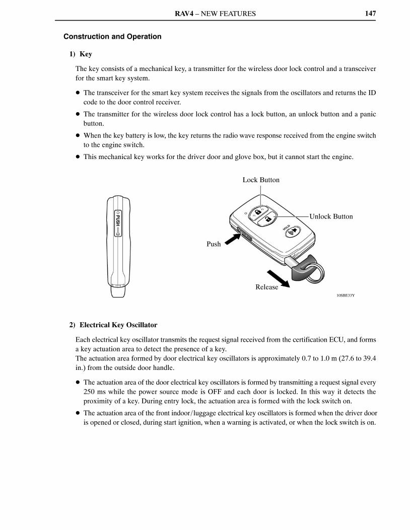
RAV4 – NEW FEATURES
10SBE33Y
Lock Button
Unlock Button
Push
Release
147
Construction and Operation
1) Key
The key consists of a mechanical key, a transmitter for the wireless door lock control and a transceiverfor the smart key system.
� The transceiver for the smart key system receives the signals from the oscillators and returns the IDcode to the door control receiver.
� The transmitter for the wireless door lock control has a lock button, an unlock button and a panicbutton.
� When the key battery is low, the key returns the radio wave response received from the engine switchto the engine switch.
� This mechanical key works for the driver door and glove box, but it cannot start the engine.
2) Electrical Key Oscillator
Each electrical key oscillator transmits the request signal received from the certification ECU, and formsa key actuation area to detect the presence of a key.The actuation area formed by door electrical key oscillators is approximately 0.7 to 1.0 m (27.6 to 39.4in.) from the outside door handle.
� The actuation area of the door electrical key oscillators is formed by transmitting a request signal every250 ms while the power source mode is OFF and each door is locked. In this way it detects theproximity of a key. During entry lock, the actuation area is formed with the lock switch on.
� The actuation area of the front indoor/luggage electrical key oscillators is formed when the driver dooris opened or closed, during start ignition, when a warning is activated, or when the lock switch is on.
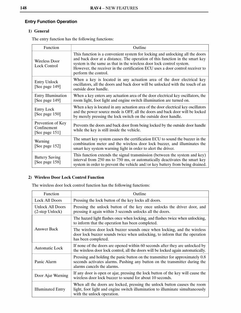
RAV4 – NEW FEATURES148
Entry Function Operation
1) General
The entry function has the following functions:
Function Outline
Wireless DoorLock Control
This function is a convenient system for locking and unlocking all the doorsand back door at a distance. The operation of this function in the smart keysystem is the same as that in the wireless door lock control system.However, the receiver in the certification ECU uses a door control receiver toperform the control.
Entry Unlock[See page 149]
When a key is located in any actuation area of the door electrical keyoscillators, all the doors and back door will be unlocked with the touch of anoutside door handle.
Entry Illumination[See page 149]
When a key enters any actuation area of the door electrical key oscillators, theroom light, foot light and engine switch illumination are turned on.
Entry Lock[See page 150]
When a key is located in any actuation area of the door electrical key oscillatorsand the power source mode is OFF, all the doors and back door will be lockedby merely pressing the lock switch on the outside door handle.
Prevention of KeyConfinement[See page 151]
Prevents the doors and back door from being locked by the outside door handlewhile the key is still inside the vehicle.
Warning[See page 152]
The smart key system causes the certification ECU to sound the buzzer in thecombination meter and the wireless door lock buzzer, and illuminates thesmart key system warning light in order to alert the driver.
Battery Saving[See page 158]
This function extends the signal transmission (between the system and key)interval from 250 ms to 750 ms, or automatically deactivates the smart keysystem in order to prevent the vehicle and/or key battery from being drained.
2) Wireless Door Lock Control Function
The wireless door lock control function has the following functions:
Function Outline
Lock All Doors Pressing the lock button of the key locks all doors.
Unlock All Doors(2-step Unlock)
Pressing the unlock button of the key once unlocks the driver door, andpressing it again within 3 seconds unlocks all the doors.
Answer Back
The hazard light flashes once when locking, and flashes twice when unlocking,to inform that the operation has been completed.
The wireless door lock buzzer sounds once when locking, and the wirelessdoor lock buzzer sounds twice when unlocking, to inform that the operationhas been completed.
Automatic LockIf none of the doors are opened within 60 seconds after they are unlocked bythe wireless door lock control, all the doors will be locked again automatically.
Panic AlarmPressing and holding the panic button on the transmitter for approximately 0.8seconds activates alarms. Pushing any button on the transmitter during thealarms cancels the alarms.
Door Ajar WarningIf any door is open or ajar, pressing the lock button of the key will cause thewireless door lock buzzer to sound for about 10 seconds.
Illuminated EntryWhen all the doors are locked, pressing the unlock button causes the roomlight, foot light and engine switch illumination to illuminate simultaneouslywith the unlock operation.
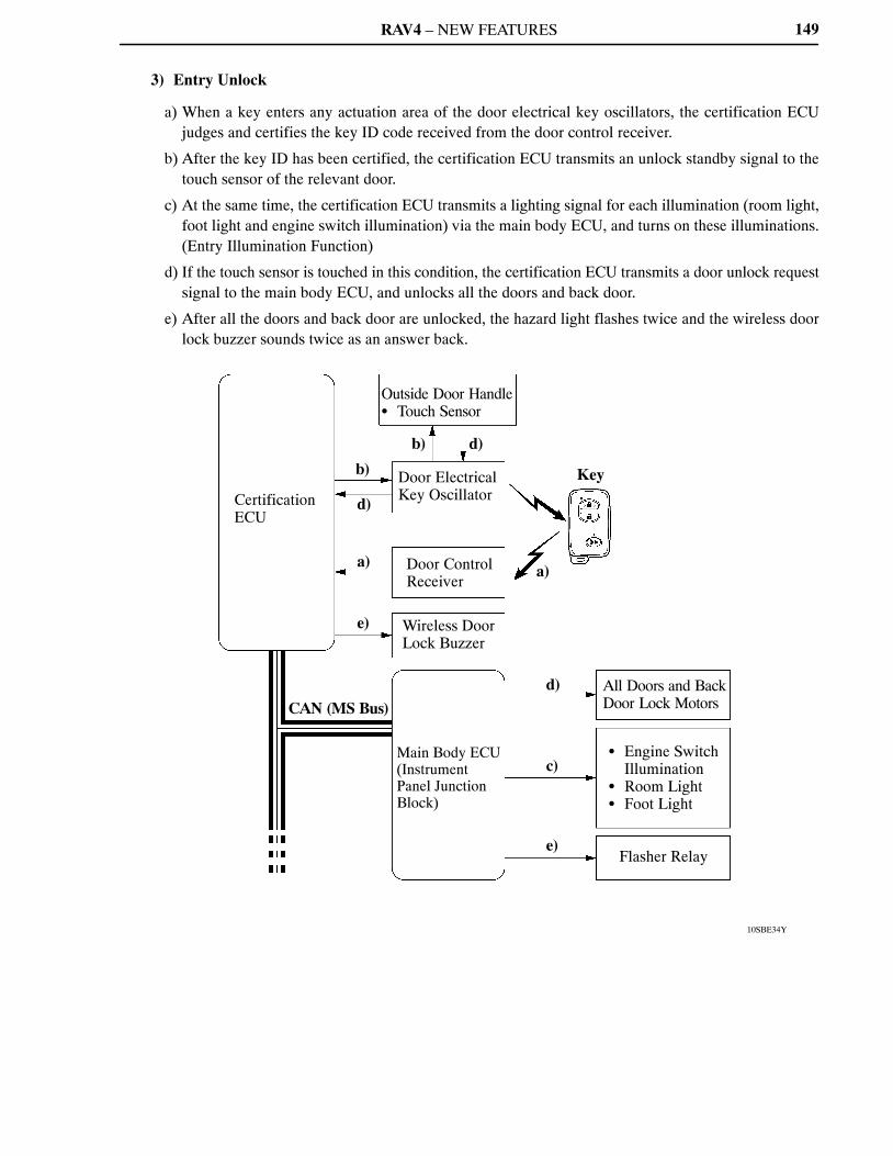
RAV4 – NEW FEATURES
c)
10SBE34Y
Certification ECU
b)
d)
a)
e)
Outside Door Handle� Touch Sensor
b) d)
CAN (MS Bus)
Door ElectricalKey Oscillator
Door Control Receiver
Wireless Door Lock Buzzer
Main Body ECU(Instrument Panel Junction Block)
Key
a)
d)
e)
All Doors and Back Door Lock Motors
� Engine Switch Illumination
� Room Light� Foot Light
Flasher Relay
149
3) Entry Unlock
a) When a key enters any actuation area of the door electrical key oscillators, the certification ECUjudges and certifies the key ID code received from the door control receiver.
b) After the key ID has been certified, the certification ECU transmits an unlock standby signal to thetouch sensor of the relevant door.
c) At the same time, the certification ECU transmits a lighting signal for each illumination (room light,foot light and engine switch illumination) via the main body ECU, and turns on these illuminations.(Entry Illumination Function)
d) If the touch sensor is touched in this condition, the certification ECU transmits a door unlock requestsignal to the main body ECU, and unlocks all the doors and back door.
e) After all the doors and back door are unlocked, the hazard light flashes twice and the wireless doorlock buzzer sounds twice as an answer back.

RAV4 – NEW FEATURES
10SBE35Y
b)
Front Indoor/Luggage Electrical Key Oscillators
b)
All Doors and Back DoorCourtesy Switches
Certification ECU
d)
d) Main Body ECU(Instrument Panel Junction Block)
CAN (MS Bus)
a)
b)
d)
g)
Outside Door Handle� Lock Switch
Door ElectricalKey Oscillator
Door Control Receiver
Wireless Door Lock Buzzer
All Doors and Back DoorLock Motors
Flasher Relay
Keyb)
c)
150
4) Entry Lock
a) The lock signal is transmitted to the certification ECU when the driver exits the vehicle with the keycarried in the driver’s possession and presses the lock switch.
b) The certification ECU transmits a request signal for the door electrical key oscillators and the frontindoor/luggage electrical key oscillators to form actuation areas.
c) The key transmits the ID code to the door control receiver.
d) The certification ECU judges and certifies the ID code from the door control receiver. It then checksthe location of the key, and when all the doors and back door are closed, the ECU transmits a door lockrequest signal to the main body ECU.
e) The main body ECU actuates the door lock motors to lock all the doors and back door.
f) After all the doors and back door are locked, the hazard light flashes once and the wireless door lockbuzzer sounds once as an answer back.
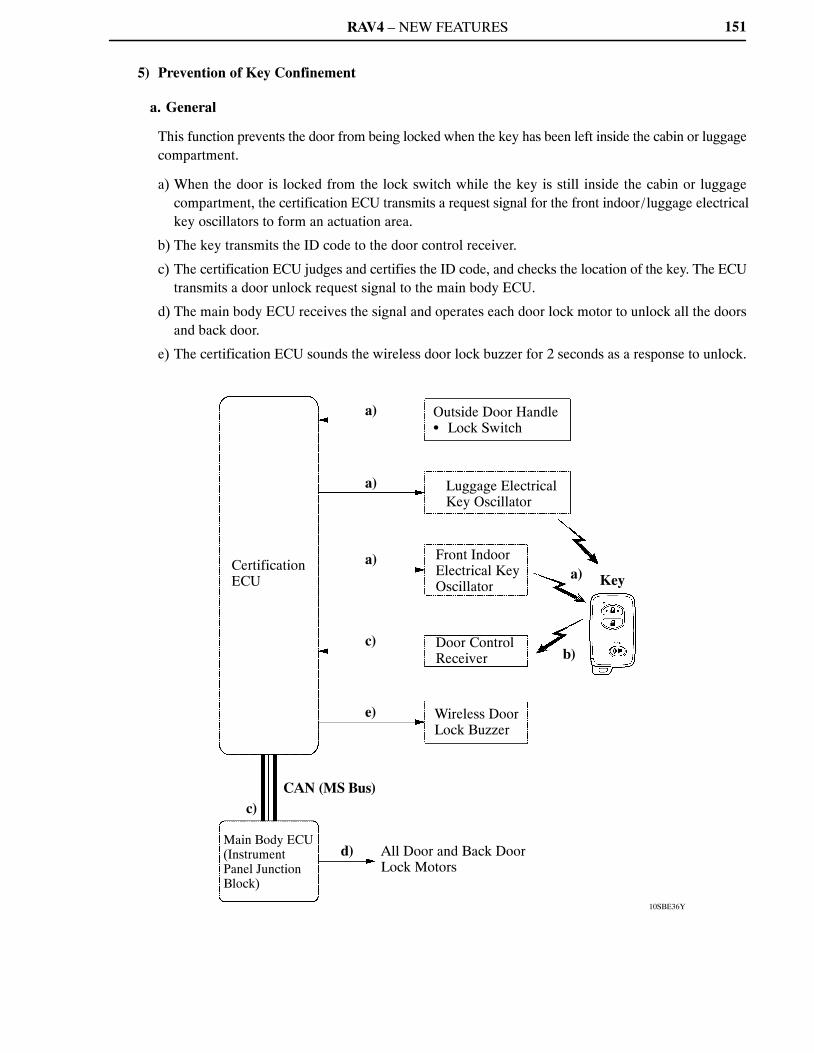
RAV4 – NEW FEATURES
10SBE36Y
Certification ECU
CAN (MS Bus)c)
Main Body ECU(Instrument Panel Junction Block)
a)
a)
a)
c)
e)
d) All Door and Back Door Lock Motors
Outside Door Handle� Lock Switch
Luggage Electrical Key Oscillator
Front Indoor Electrical Key Oscillator
Door Control Receiver
Wireless Door Lock Buzzer
a) Key
b)
151
5) Prevention of Key Confinement
a. General
This function prevents the door from being locked when the key has been left inside the cabin or luggagecompartment.
a) When the door is locked from the lock switch while the key is still inside the cabin or luggagecompartment, the certification ECU transmits a request signal for the front indoor/luggage electricalkey oscillators to form an actuation area.
b) The key transmits the ID code to the door control receiver.
c) The certification ECU judges and certifies the ID code, and checks the location of the key. The ECUtransmits a door unlock request signal to the main body ECU.
d) The main body ECU receives the signal and operates each door lock motor to unlock all the doorsand back door.
e) The certification ECU sounds the wireless door lock buzzer for 2 seconds as a response to unlock.
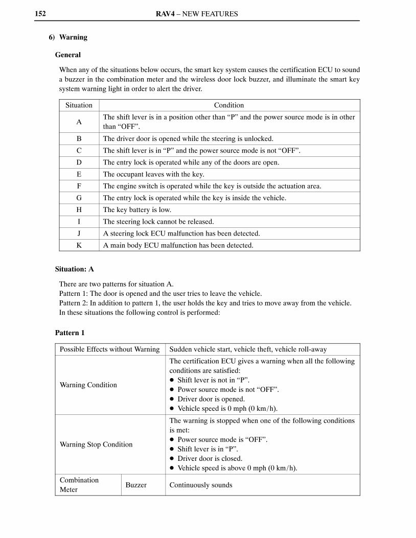
RAV4 – NEW FEATURES152
6) Warning
General
When any of the situations below occurs, the smart key system causes the certification ECU to sounda buzzer in the combination meter and the wireless door lock buzzer, and illuminate the smart keysystem warning light in order to alert the driver.
Situation Condition
AThe shift lever is in a position other than “P” and the power source mode is in otherthan “OFF”.
B The driver door is opened while the steering is unlocked.
C The shift lever is in “P” and the power source mode is not “OFF”.
D The entry lock is operated while any of the doors are open.
E The occupant leaves with the key.
F The engine switch is operated while the key is outside the actuation area.
G The entry lock is operated while the key is inside the vehicle.
H The key battery is low.
I The steering lock cannot be released.
J A steering lock ECU malfunction has been detected.
K A main body ECU malfunction has been detected.
Situation: A
There are two patterns for situation A.Pattern 1: The door is opened and the user tries to leave the vehicle.Pattern 2: In addition to pattern 1, the user holds the key and tries to move away from the vehicle.In these situations the following control is performed:
Pattern 1
Possible Effects without Warning Sudden vehicle start, vehicle theft, vehicle roll-away
Warning Condition
The certification ECU gives a warning when all the followingconditions are satisfied:� Shift lever is not in “P”.� Power source mode is not “OFF”.� Driver door is opened.� Vehicle speed is 0 mph (0 km/h).
Warning Stop Condition
The warning is stopped when one of the following conditionsis met:� Power source mode is “OFF”.� Shift lever is in “P”.� Driver door is closed.� Vehicle speed is above 0 mph (0 km/h).
CombinationMeter
Buzzer Continuously sounds
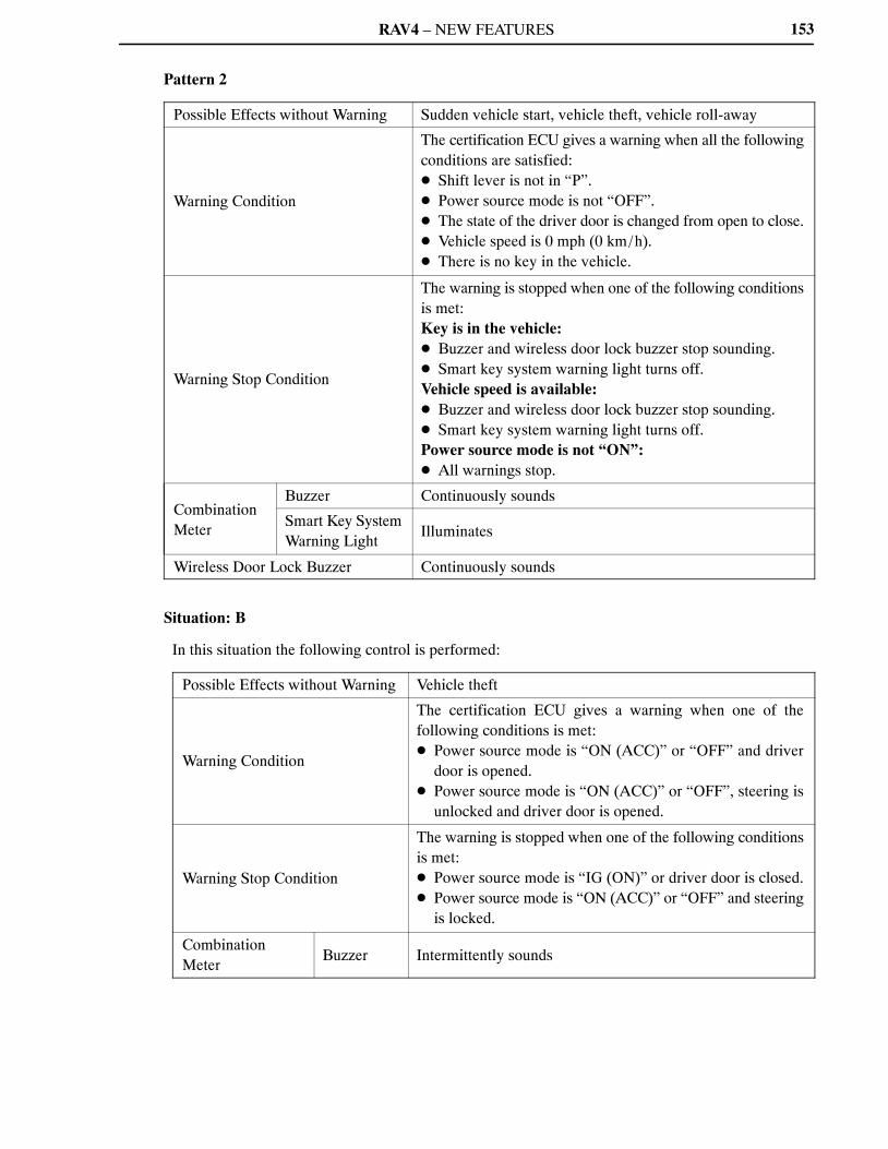
RAV4 – NEW FEATURES 153
Pattern 2
Possible Effects without Warning Sudden vehicle start, vehicle theft, vehicle roll-away
Warning Condition
The certification ECU gives a warning when all the followingconditions are satisfied:� Shift lever is not in “P”.� Power source mode is not “OFF”.� The state of the driver door is changed from open to close.� Vehicle speed is 0 mph (0 km/h).� There is no key in the vehicle.
Warning Stop Condition
The warning is stopped when one of the following conditionsis met:Key is in the vehicle:� Buzzer and wireless door lock buzzer stop sounding.� Smart key system warning light turns off.Vehicle speed is available:� Buzzer and wireless door lock buzzer stop sounding.� Smart key system warning light turns off.Power source mode is not “ON”:� All warnings stop.
CombinationMeter
Buzzer Continuously sounds
Smart Key SystemWarning Light
Illuminates
Wireless Door Lock Buzzer Continuously sounds
Situation: B
In this situation the following control is performed:
Possible Effects without Warning Vehicle theft
Warning Condition
The certification ECU gives a warning when one of thefollowing conditions is met:� Power source mode is “ON (ACC)” or “OFF” and driver
door is opened.� Power source mode is “ON (ACC)” or “OFF”, steering is
unlocked and driver door is opened.
Warning Stop Condition
The warning is stopped when one of the following conditionsis met:� Power source mode is “IG (ON)” or driver door is closed.� Power source mode is “ON (ACC)” or “OFF” and steering
is locked.
CombinationMeter
Buzzer Intermittently sounds
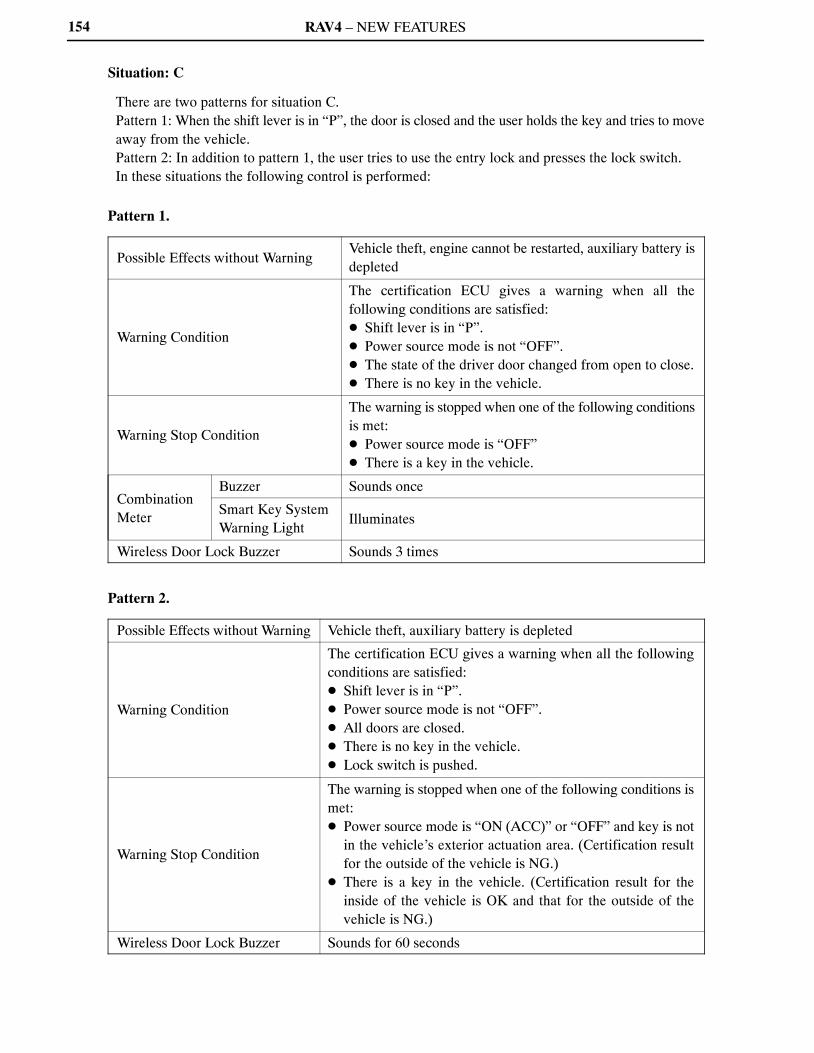
RAV4 – NEW FEATURES154
Situation: C
There are two patterns for situation C.Pattern 1: When the shift lever is in “P”, the door is closed and the user holds the key and tries to moveaway from the vehicle.Pattern 2: In addition to pattern 1, the user tries to use the entry lock and presses the lock switch.In these situations the following control is performed:
Pattern 1.
Possible Effects without WarningVehicle theft, engine cannot be restarted, auxiliary battery isdepleted
Warning Condition
The certification ECU gives a warning when all thefollowing conditions are satisfied:� Shift lever is in “P”.� Power source mode is not “OFF”.� The state of the driver door changed from open to close.� There is no key in the vehicle.
Warning Stop Condition
The warning is stopped when one of the following conditionsis met:� Power source mode is “OFF”� There is a key in the vehicle.
CombinationMeter
Buzzer Sounds once
Smart Key SystemWarning Light
Illuminates
Wireless Door Lock Buzzer Sounds 3 times
Pattern 2.
Possible Effects without Warning Vehicle theft, auxiliary battery is depleted
Warning Condition
The certification ECU gives a warning when all the followingconditions are satisfied:� Shift lever is in “P”.� Power source mode is not “OFF”.� All doors are closed.� There is no key in the vehicle.� Lock switch is pushed.
Warning Stop Condition
The warning is stopped when one of the following conditions ismet:� Power source mode is “ON (ACC)” or “OFF” and key is not
in the vehicle’s exterior actuation area. (Certification resultfor the outside of the vehicle is NG.)
� There is a key in the vehicle. (Certification result for theinside of the vehicle is OK and that for the outside of thevehicle is NG.)
Wireless Door Lock Buzzer Sounds for 60 seconds
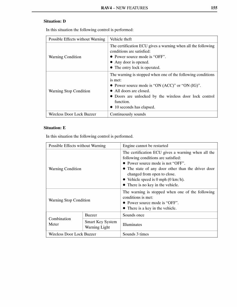
RAV4 – NEW FEATURES 155
Situation: D
In this situation the following control is performed:
Possible Effects without Warning Vehicle theft
Warning Condition
The certification ECU gives a warning when all the followingconditions are satisfied:� Power source mode is “OFF”.� Any door is opened.� The entry lock is operated.
Warning Stop Condition
The warning is stopped when one of the following conditionsis met:� Power source mode is “ON (ACC)” or “ON (IG)”.� All doors are closed.� Doors are unlocked by the wireless door lock control
function.� 10 seconds has elapsed.
Wireless Door Lock Buzzer Continuously sounds
Situation: E
In this situation the following control is performed.
Possible Effects without Warning Engine cannot be restarted
Warning Condition
The certification ECU gives a warning when all thefollowing conditions are satisfied:� Power source mode is not “OFF”.� The state of any door other than the driver door
changed from open to close.� Vehicle speed is 0 mph (0 km/h).� There is no key in the vehicle.
Warning Stop Condition
The warning is stopped when one of the followingconditions is met:� Power source mode is “OFF”.� There is a key in the vehicle.
CombinationMeter
Buzzer Sounds once
Smart Key SystemWarning Light
Illuminates
Wireless Door Lock Buzzer Sounds 3 times

RAV4 – NEW FEATURES156
Situation: F
In this situation the following control is performed:
Possible Effects without Warning Confuses the driver
Warning Condition
The certification ECU gives a warning when all thefollowing conditions are satisfied:� Engine switch is pushed.� There is no key in the vehicle.
CombinationMeter
Buzzer Sounds once
Smart Key SystemWarning Light
Illuminates for 8 seconds
Situation: G
In this situation the following control is performed:
Possible Effects without Warning Vehicle theft
Warning Condition
The certification ECU gives a warning when all the followingconditions are satisfied:� Power source mode is “OFF”.� All doors are closed.� Lock switch is pushed.� There is a key in the vehicle.
Wireless Door Lock Buzzer Sounds for 2 seconds
Situation: H
In this situation the following control is performed:
Possible Effects without Warning Smart key system does not function
Warning Condition
The certification ECU gives a warning when all the followingconditions are satisfied:� Power source mode is switched to “OFF” after being left in
“ON (IG)” for over 20 minutes.� Key battery voltage is low.� There is a key in the vehicle.
CombinationMeter
Buzzer Sounds once
Situation: I
In this situation the following control is performed:
Possible Effects without Warning Smart key system does not function
Warning ConditionThe steering lock does not release when performing therelease operation, preventing the engine from starting.
Engine Switch Indicator LightGreen color blinks in 1-second cycles.(Stops blinking after 15 seconds have elapsed.)

RAV4 – NEW FEATURES 157
Situation: J
In this situation the following control is performed:
Possible Effects without Warning Engine cannot be started
Warning ConditionAn internal malfunction in the steering lock ECU has beendetected.
Warning Stop ConditionThe internal malfunction in the steering lock ECU has beencleared.
Engine Switch Indicator Light Amber light blinks in 2-second cycles.
Situation: K
In this situation the following control is performed:
Possible Effects without Warning Engine cannot be started
Warning ConditionAn internal malfunction in the main body ECU has beendetected.
Warning Stop ConditionThe internal malfunction in the main body ECU has beencleared.
Engine Switch Indicator Light Amber light blinks in 2-second cycles.
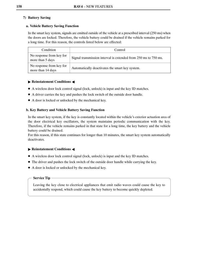
RAV4 – NEW FEATURES
Service Tip
Leaving the key close to electrical appliances that emit radio waves could cause the key toaccidentally respond, which could cause the key battery to become quickly depleted.
158
7) Battery Saving
a. Vehicle Battery Saving Function
In the smart key system, signals are emitted outside of the vehicle at a prescribed interval (250 ms) whenthe doors are locked. Therefore, the vehicle battery could be drained if the vehicle remains parked fora long time. For this reason, the controls listed below are effected:
Condition Control
No response from key formore than 5 days
Signal transmission interval is extended from 250 ms to 750 ms.
No response from key formore than 14 days
Automatically deactivates the smart key system.
� Reinstatement Conditions �
� A wireless door lock control signal (lock, unlock) is input and the key ID matches.
� A driver carries the key and pushes the lock switch of the outside door handle.
� A door is locked or unlocked by the mechanical key.
b. Key Battery and Vehicle Battery Saving Function
In the smart key system, if the key is constantly located within the vehicle’s exterior actuation area ofthe door electrical key oscillators, the system maintains periodic communication with the key.Therefore, if the vehicle remains parked in that state for a long time, the key battery and the vehiclebattery could be drained.For this reason, if this state continues for longer than 10 minutes, the smart key system automaticallydeactivates.
� Reinstatement Conditions �
� A wireless door lock control signal (lock, unlock) is input and the key ID matches.
� The driver and pushes the lock switch of the outside door handle while carrying the key.
� A door is locked or unlocked by the mechanical key.
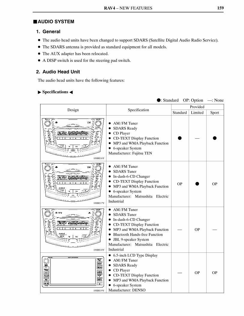
RAV4 – NEW FEATURES
10SBE16Y
10SBE17Y
10SBE18Y
10SBE19Y
159
�AUDIO SYSTEM
1. General
� The audio head units have been changed to support SDARS (Satellite Digital Audio Radio Service).
� The SDARS antenna is provided as standard equipment for all models.
� The AUX adapter has been relocated.
� A DISP switch is used for the steering pad switch.
2. Audio Head Unit
The audio head units have the following features:
� Specifications �
�: Standard OP: Option —: None
Design SpecificationProvided
Standard Limited Sport
� AM/FM Tuner� SDARS Ready� CD Player� CD-TEXT Display Function� MP3 and WMA Playback Function� 6-speaker SystemManufacturer: Fujitsu TEN
� — �
� AM/FM Tuner� SDARS Tuner� In-dash-6-CD Changer� CD-TEXT Display Function� MP3 and WMA Playback Function� 6-speaker SystemManufacturer: Matsushita ElectricIndustrial
OP � OP
� AM/FM Tuner� SDARS Tuner� In-dash-6-CD Changer� CD-TEXT Display Function� MP3 and WMA Playback Function� Bluetooth Hands-free Function� JBL 9-speaker SystemManufacturer: Matsushita ElectricIndustrial
— OP —
� 6.5-inch LCD Type Display� AM/FM Tuner� SDARS Ready� CD Player� CD-TEXT Display Function� MP3 and WMA Playback Function� 6-speaker SystemManufacturer: DENSO
— OP OP
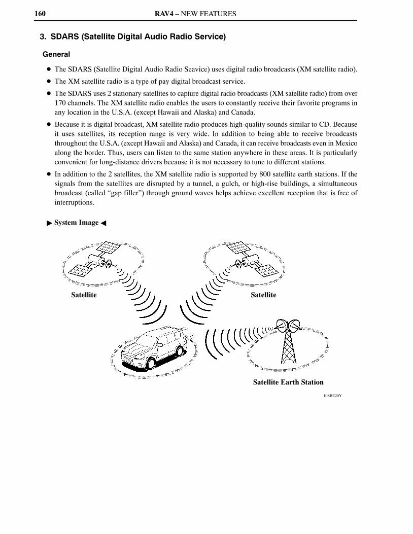
RAV4 – NEW FEATURES
10SBE20Y
Satellite Satellite
Satellite Earth Station
160
3. SDARS (Satellite Digital Audio Radio Service)
General
� The SDARS (Satellite Digital Audio Radio Seavice) uses digital radio broadcasts (XM satellite radio).
� The XM satellite radio is a type of pay digital broadcast service.
� The SDARS uses 2 stationary satellites to capture digital radio broadcasts (XM satellite radio) from over170 channels. The XM satellite radio enables the users to constantly receive their favorite programs inany location in the U.S.A. (except Hawaii and Alaska) and Canada.
� Because it is digital broadcast, XM satellite radio produces high-quality sounds similar to CD. Becauseit uses satellites, its reception range is very wide. In addition to being able to receive broadcaststhroughout the U.S.A. (except Hawaii and Alaska) and Canada, it can receive broadcasts even in Mexicoalong the border. Thus, users can listen to the same station anywhere in these areas. It is particularlyconvenient for long-distance drivers because it is not necessary to tune to different stations.
� In addition to the 2 satellites, the XM satellite radio is supported by 800 satellite earth stations. If thesignals from the satellites are disrupted by a tunnel, a gulch, or high-rise buildings, a simultaneousbroadcast (called “gap filler”) through ground waves helps achieve excellent reception that is free ofinterruptions.
� System Image �

RAV4 – NEW FEATURES
10SBE21Y
Audio Head Unit� SDARS Tuner SDARS Antenna
161
Layout of Main Components

RAV4 – NEW FEATURES
10SBE39Y
AUX Adapter
162
4. AUX Adapter
The AUX adapter has been relocated to the console.
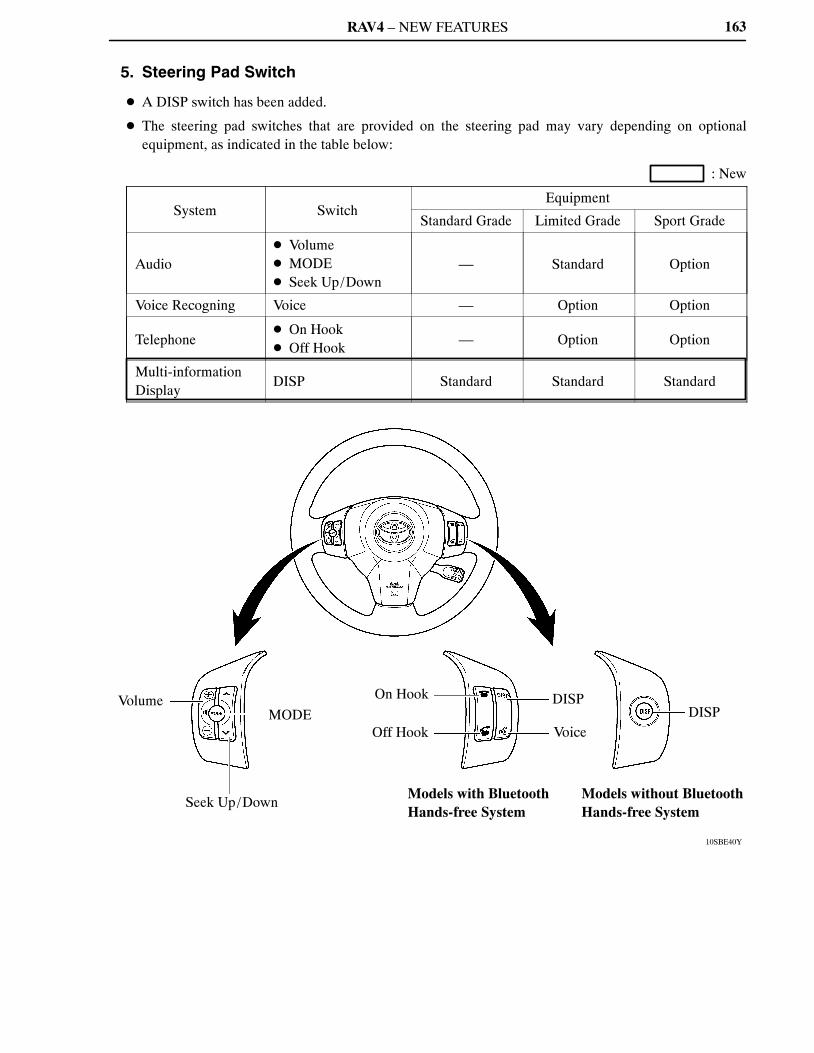
RAV4 – NEW FEATURES
10SBE40Y
Volume
Seek Up/Down
MODE
On Hook
Off Hook
Models with Bluetooth Hands-free System
DISP
VoiceDISP
Models without Bluetooth Hands-free System
163
5. Steering Pad Switch
� A DISP switch has been added.
� The steering pad switches that are provided on the steering pad may vary depending on optionalequipment, as indicated in the table below:
: New
System SwitchEquipment
Standard Grade Limited Grade Sport Grade
Audio� Volume� MODE� Seek Up/Down
— Standard Option
Voice Recogning Voice — Option Option
Telephone� On Hook� Off Hook
— Option Option
Multi-informationDisplay
DISP Standard Standard Standard
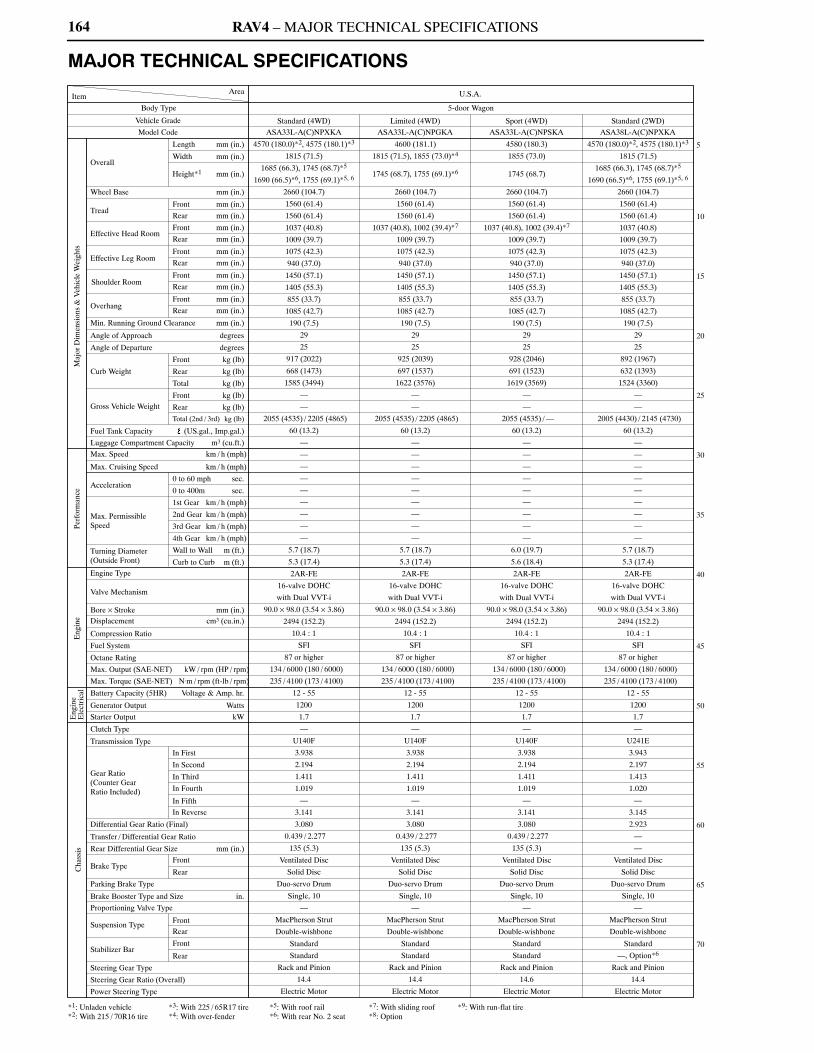
RAV4 – MAJOR TECHNICAL SPECIFICATIONS
Standard (4WD)
U.S.A.
5-door Wagon
Model Code
Vehicle Grade
Body Type
Rear mm (in.)
Front mm (in.)
Wheel Base mm (in.)
Height*1 mm (in.)
Width mm (in.)
Length mm (in.)
ItemArea
Overall
Tread
Effective Head RoomFront mm (in.)
Rear mm (in.)
Front mm (in.)
Rear mm (in.)
Front mm (in.)
Rear mm (in.)
Front mm (in.)
Rear mm (in.)
Effective Leg Room
Shoulder Room
Overhang
Min. Running Ground Clearance mm (in.)
Angle of Approach degrees
Angle of Departure degrees
Curb Weight
Gross Vehicle Weight
Front kg (lb)
Rear kg (lb)
Total kg (lb)
Front kg (lb)
Rear kg (lb)
Total (2nd / 3rd) kg (lb)
Fuel Tank Capacity (US.gal., Imp.gal.)
Luggage Compartment Capacity m3 (cu.ft.)
Max. Speed km / h (mph)
Max. Cruising Speed km / h (mph)
Acceleration
Turning Diameter(Outside Front)
0 to 60 mph sec.
0 to 400m sec.
3rd Gear km / h (mph)
4th Gear km / h (mph)
Wall to Wall m (ft.)
Curb to Curb m (ft.)Engine Type
Valve Mechanism
Bore × Stroke mm (in.)Displacement cm3 (cu.in.)
Compression Ratio
Fuel System
Octane Rating
Max. Output (SAE-NET) kW / rpm (HP / rpm)
Max. Torque (SAE-NET) N.m / rpm (ft-lb / rpm)
Battery Capacity (5HR) Voltage & Amp. hr.
Generator Output Watts
Starter Output kW
Clutch Type
Transmission Type
Gear Ratio(Counter GearRatio Included)
Differential Gear Ratio (Final)
Transfer / Differential Gear Ratio
Brake Type
Parking Brake Type
Brake Booster Type and Size in.
Proportioning Valve Type
Suspension Type
Stabilizer Bar
Steering Gear Type
Steering Gear Ratio (Overall)
Power Steering Type
In First
In Second
In Third
In Fourth
In Fifth
In Reverse
Front
Rear
FrontRear
Front
Rear
5
10
15
20
25
30
35
40
45
50
55
60
65
70
Maj
or D
imen
sion
s &
Veh
icle
Wei
ghts
Perf
orm
ance
Eng
ine
Eng
ine
Cha
ssis
Ele
ctri
cal
Limited (4WD) Sport (4WD) Standard (2WD)
Rear Differential Gear Size mm (in.)
1st Gear km / h (mph)
2nd Gear km / h (mph)Max. PermissibleSpeed
1745 (68.7), 1755 (69.1)*6 1745 (68.7)
164
MAJOR TECHNICAL SPECIFICATIONS
ASA33L-A(C)NPXKA ASA33L-A(C)NPGKA ASA33L-A(C)NPSKA ASA38L-A(C)NPXKA
4570 (180.0)*2, 4575 (180.1)*3 4600 (181.1) 4580 (180.3) 4570 (180.0)*2, 4575 (180.1)*3
1815 (71.5) 1815 (71.5), 1855 (73.0)*4 1855 (73.0) 1815 (71.5)
1685 (66.3), 1745 (68.7)*5 1685 (66.3), 1745 (68.7)*5
1690 (66.5)*6, 1755 (69.1)*5, 6 1690 (66.5)*6, 1755 (69.1)*5, 6
2660 (104.7) 2660 (104.7) 2660 (104.7) 2660 (104.7)
1560 (61.4) 1560 (61.4) 1560 (61.4) 1560 (61.4)
1560 (61.4) 1560 (61.4) 1560 (61.4) 1560 (61.4)
1037 (40.8) 1037 (40.8), 1002 (39.4)*7 1037 (40.8), 1002 (39.4)*7 1037 (40.8)
1009 (39.7) 1009 (39.7) 1009 (39.7) 1009 (39.7)
1075 (42.3) 1075 (42.3) 1075 (42.3) 1075 (42.3)
940 (37.0) 940 (37.0) 940 (37.0) 940 (37.0)
1450 (57.1) 1450 (57.1) 1450 (57.1) 1450 (57.1)
1405 (55.3) 1405 (55.3) 1405 (55.3) 1405 (55.3)
855 (33.7) 855 (33.7) 855 (33.7) 855 (33.7)
1085 (42.7) 1085 (42.7) 1085 (42.7) 1085 (42.7)
190 (7.5) 190 (7.5) 190 (7.5) 190 (7.5)
29 29 29 29
25 25 25 25
917 (2022) 925 (2039) 928 (2046) 892 (1967)
668 (1473) 697 (1537) 691 (1523) 632 (1393)
1585 (3494) 1622 (3576) 1619 (3569) 1524 (3360)
— — — —
— — — —
2055 (4535) / 2205 (4865) 2055 (4535) / 2205 (4865) 2055 (4535) / — 2005 (4430) / 2145 (4730)
60 (13.2) 60 (13.2) 60 (13.2) 60 (13.2)
— — — —
— — — —
— — — —
— — — —
— — — —
— — — —
— — — —
— — — —
— — — —
5.7 (18.7) 5.7 (18.7) 6.0 (19.7) 5.7 (18.7)
5.3 (17.4) 5.3 (17.4) 5.6 (18.4) 5.3 (17.4)
2AR-FE 2AR-FE 2AR-FE 2AR-FE
16-valve DOHC 16-valve DOHC 16-valve DOHC 16-valve DOHC
with Dual VVT-i with Dual VVT-i with Dual VVT-i with Dual VVT-i
90.0 × 98.0 (3.54 × 3.86) 90.0 × 98.0 (3.54 × 3.86) 90.0 × 98.0 (3.54 × 3.86) 90.0 × 98.0 (3.54 × 3.86)
2494 (152.2) 2494 (152.2) 2494 (152.2) 2494 (152.2)
10.4 : 1 10.4 : 1 10.4 : 1 10.4 : 1
SFI SFI SFI SFI
87 or higher 87 or higher 87 or higher 87 or higher
134 / 6000 (180 / 6000) 134 / 6000 (180 / 6000) 134 / 6000 (180 / 6000) 134 / 6000 (180 / 6000)
235 / 4100 (173 / 4100) 235 / 4100 (173 / 4100) 235 / 4100 (173 / 4100) 235 / 4100 (173 / 4100)
12 - 55 12 - 55 12 - 55 12 - 55
1200 1200 1200 1200
1.7 1.7 1.7 1.7
— — — —
U140F U140F U140F U241E
3.938 3.938 3.938 3.943
2.194 2.194 2.194 2.197
1.411 1.411 1.411 1.413
1.019 1.019 1.019 1.020
— — — —
3.141 3.141 3.141 3.145
3.080 3.080 3.080 2.923
0.439 / 2.277 0.439 / 2.277 0.439 / 2.277 —
135 (5.3) 135 (5.3) 135 (5.3) —
Ventilated Disc Ventilated Disc Ventilated Disc Ventilated Disc
Solid Disc Solid Disc Solid Disc Solid Disc
Duo-servo Drum Duo-servo Drum Duo-servo Drum Duo-servo Drum
Single, 10 Single, 10 Single, 10 Single, 10
— — — —
MacPherson Strut MacPherson Strut MacPherson Strut MacPherson Strut
Double-wishbone Double-wishbone Double-wishbone Double-wishbone
Standard Standard Standard Standard
Standard Standard Standard —, Option*6
Rack and Pinion Rack and Pinion Rack and Pinion Rack and Pinion
14.4 14.4 14.6 14.4
Electric Motor Electric Motor Electric Motor Electric Motor
*1: Unladen vehicle *3: With 225 / 65R17 tire *5: With roof rail *7: With sliding roof *9: With run-flat tire*2: With 215 / 70R16 tire *4: With over-fender *6: With rear No. 2 seat *8: Option

RAV4 – MAJOR TECHNICAL SPECIFICATIONS
5
10
15
20
25
30
35
40
45
50
55
60
65
70
U.S.A.
5-door Wagon
Limited (2WD) Sport (2WD) Standard (4WD) Limited (4WD) Sport (4WD) Standard (2WD)
1745 (68.7) 1745 (68.7), 1755 (69.1)*6 1745 (68.7)
24-valve, DOHC 24-valve, DOHC24-valve, DOHC 24-valve, DOHC
1745 (68.7), 1755 (69.1)*6
165
ASA38L-A(C)NPGKA ASA38L-A(C)NPSKA GSA33L-A(C)NAXKA GSA33L-A(C)NAGKA GSA33L-A(C)NASKA GSA38L-A(C)NAXKA
4600 (181.1) 4580 (180.3) 4570 (180.0)*2, 4575 (180.1)*3 4600 (181.1) 4580 (180.3), 4500 (177.2)*9 4570 (180.0)*2, 4575 (180.1)*3
1815 (71.5), 1855 (73.0)*4 1855 (73.0) 1815 (71.5) 1815 (71.5), 1855 (73.0)*4 1855 (73.0) 1815 (71.5)
1685 (66.3), 1745 (68.7)*5 1685 (66.3), 1745 (68.7)*5
1690 (66.5)*6, 1755 (69.1)*5, 6 1690 (66.5)*6, 1755 (69.1)*5, 6
2660 (104.7) 2660 (104.7) 2660 (104.7) 2660 (104.7) 2660 (104.7) 2660 (104.7)
1560 (61.4) 1560 (61.4) 1560 (61.4) 1560 (61.4) 1560 (61.4) 1560 (61.4)
1560 (61.4) 1560 (61.4) 1560 (61.4) 1560 (61.4) 1560 (61.4) 1560 (61.4)
1037 (40.8), 1002 (39.4)*7 1037 (40.8), 1002 (39.4)*7 1037 (40.8) 1037 (40.8), 1002 (39.4)*7 1037 (40.8), 1002 (39.4)*7 1037 (40.8)
1009 (39.7) 1009 (39.7) 1009 (39.7) 1009 (39.7) 1009 (39.7) 1009 (39.7)
1075 (42.3) 1075 (42.3) 1075 (42.3) 1075 (42.3) 1075 (42.3) 1075 (42.3)
940 (37.0) 940 (37.0) 940 (37.0) 940 (37.0) 940 (37.0) 940 (37.0)
1450 (57.1) 1450 (57.1) 1450 (57.1) 1450 (57.1) 1450 (57.1) 1450 (57.1)
1405 (55.3) 1405 (55.3) 1405 (55.3) 1405 (55.3) 1405 (55.3) 1405 (55.3)
855 (33.7) 855 (33.7) 855 (33.7) 855 (33.7) 855 (33.7) 855 (33.7)
1085 (42.7) 1085 (42.7) 1085 (42.7) 1085 (42.7) 1085 (42.7) 1085 (42.7)
190 (7.5) 190 (7.5) 190 (7.5) 190 (7.5) 190 (7.5) 190 (7.5)
29 29 29 29 29 29
25 25 25 25 25 25
900 (1984) 903 (1991) 975 (2150) 975 (2150) 979 (2158) 950 (2094)
660 (1455) 655 (1444) 690 (1521) 703 (1550) 699 (1541) 651 (1435)
1560 (3439) 1558 (3435) 1665 (3671) 1678 (3699) 1678 (3699) 1601 (3530)
— — — — — —
— — — — — —
2005 (4430) / 2145 (4730) 2005 (4430) / — 2140 (4720) / 2270 (5015) 2140 (4720) / 2270 (5015) 2140 (4720) / — 2085 (4600) / 2220 (4895)
60 (13.2) 60 (13.2) 60 (13.2) 60 (13.2) 60 (13.2) 60 (13.2)
— — — — — —
— — — — — —
— — — — — —
— — — — — —
— — — — — —
— — — — — —
— — — — — —
— — — — — —
— — — — — —
5.7 (18.7) 6.0 (19.7) 6.0 (19.7) 6.0 (19.7) 6.0 (19.7) 6.0 (19.7)
5.3 (17.4) 5.6 (18.4) 5.6 (18.4) 5.6 (18.4) 5.6 (18.4) 5.6 (18.4)
2AR-FE 2AR-FE 2GR-FE 2GR-FE 2GR-FE 2GR-FE
16-valve DOHC 16-valve DOHC
with Dual VVT-i with Dual VVT-i
90.0 × 98.0 (3.54 × 3.86) 90.0 × 98.0 (3.54 × 3.86) 94.0 × 83.0 (3.70 × 3.27) 94.0 × 83.0 (3.70 × 3.27) 94.0 × 83.0 (3.70 × 3.27) 94.0 × 83.0 (3.70 × 3.27)
2494 (152.2) 2494 (152.2) 3456 (210.9) 3456 (210.9) 3456 (210.9) 3456 (210.9)
10.4 : 1 10.4 : 1 10.8 : 1 10.8 : 1 10.8 : 1 10.8 : 1
SFI SFI SFI SFI SFI SFI
87 or higher 87 or higher 91 or higher 91 or higher 91 or higher 91 or higher
134 / 6000 (180 / 6000) 134 / 6000 (180 / 6000) 200 / 6200 (268 / 6200) 200 / 6200 (268 / 6200) 200 / 6200 (268 / 6200) 200 / 6200 (268 / 6200)
235 / 4100 (173 / 4100) 235 / 4100 (173 / 4100) 336 / 4700 (248 / 4700) 336 / 4700 (248 / 4700) 336 / 4700 (248 / 4700) 336 / 4700 (248 / 4700)
12 - 55 12 - 55 12 - 55 12 - 55 12 - 55 12 - 55
1200 1200 1200, 1800*8 1200, 1800*8 1200, 1800*8 1200, 1800*8
1.7 1.7 1.7 1.7 1.7 1.7
— — — — — —
U241E U241E U151F U151F U151F U151E
3.943 3.943 4.235 4.235 4.235 4.235
2.197 2.197 2.360 2.360 2.360 2.360
1.413 1.413 1.517 1.517 1.517 1.517
1.020 1.020 1.047 1.047 1.047 1.047
— — 0.756 0.756 0.756 0.756
3.145 3.145 3.378 3.378 3.378 3.378
2.923 2.923 3.080 3.080 3.080 3.080
— — 0.439 / 2.277 0.439 / 2.277 0.439 / 2.277 —
— — 135 (5.3) 135 (5.3) 135 (5.3) —
Ventilated Disc Ventilated Disc Ventilated Disc Ventilated Disc Ventilated Disc Ventilated Disc
Solid Disc Solid Disc Solid Disc Solid Disc Solid Disc Solid Disc
Duo-servo Drum Duo-servo Drum Duo-servo Drum Duo-servo Drum Duo-servo Drum Duo-servo Drum
Single, 10 Single, 10 Single, 10 Single, 10 Single, 10 Single, 10
— — — — — —
MacPherson Strut MacPherson Strut MacPherson Strut MacPherson Strut MacPherson Strut MacPherson Strut
Double-wishbone Double-wishbone Double-wishbone Double-wishbone Double-wishbone Double-wishbone
Standard Standard Standard Standard Standard Standard
—, Option*6 — Standard Standard Standard Standard
Rack and Pinion Rack and Pinion Rack and Pinion Rack and Pinion Rack and Pinion Rack and Pinion
14.4 14.6 14.4 14.4 14.6 14.4
Electric Motor Electric Motor Electric Motor Electric Motor Electric Motor Electric Motor
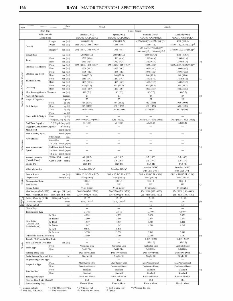
RAV4 – MAJOR TECHNICAL SPECIFICATIONS
Limited (2WD)
U.S.A.
5-door Wagon
Model Code
Vehicle Grade
Body Type
Rear mm (in.)
Front mm (in.)
Wheel Base mm (in.)
Height*1 mm (in.)
Width mm (in.)
Length mm (in.)
ItemArea
Overall
Tread
Effective Head RoomFront mm (in.)
Rear mm (in.)
Front mm (in.)
Rear mm (in.)
Front mm (in.)
Rear mm (in.)
Front mm (in.)
Rear mm (in.)
Effective Leg Room
Shoulder Room
Overhang
Min. Running Ground Clearance mm (in.)
Angle of Approach degrees
Angle of Departure degrees
Curb Weight
Gross Vehicle Weight
Front kg (lb)
Rear kg (lb)
Total kg (lb)
Front kg (lb)
Rear kg (lb)
Total (2nd / 3rd) kg (lb)
Fuel Tank Capacity (US.gal., Imp.gal.)
Luggage Compartment Capacity m3 (cu.ft.)
Max. Speed km / h (mph)
Max. Cruising Speed km / h (mph)
Acceleration
Turning Diameter(Outside Front)
0 to 60 mph sec.
0 to 400m sec.
3rd Gear km / h (mph)
4th Gear km / h (mph)
Wall to Wall m (ft.)
Curb to Curb m (ft.)Engine Type
Valve Mechanism
Bore × Stroke mm (in.)Displacement cm3 (cu.in.)
Compression Ratio
Fuel System
Octane Rating
Max. Output (SAE-NET) kW / rpm (HP / rpm)
Max. Torque (SAE-NET) N.m / rpm (ft-lb / rpm)
Battery Capacity (5HR) Voltage & Amp. hr.
Generator Output Watts
Starter Output kW
Clutch Type
Transmission Type
Gear Ratio(Counter GearRatio Included)
Differential Gear Ratio (Final)
Transfer / Differential Gear Ratio
Brake Type
Parking Brake Type
Brake Booster Type and Size in.
Proportioning Valve Type
Suspension Type
Stabilizer Bar
Steering Gear Type
Steering Gear Ratio (Overall)
Power Steering Type
In First
In Second
In Third
In Fourth
In Fifth
In Reverse
Front
Rear
FrontRear
Front
Rear
5
10
15
20
25
30
35
40
45
50
55
60
65
70
Maj
or D
imen
sion
s &
Veh
icle
Wei
ghts
Perf
orm
ance
Eng
ine
Eng
ine
Cha
ssis
Ele
ctri
cal
Sport (2WD) Standard (4WD) Limited (4WD)
Rear Differential Gear Size mm (in.)
1st Gear km / h (mph)
2nd Gear km / h (mph)Max. PermissibleSpeed
Canada
1745 (68.7), 1755 (69.1)*6 1745 (68.7) 1745 (68.7), 1755 (69.1)*6
24-valve, DOHC 24-valve, DOHC
166
GSA38L-A(C)NAGKA GSA38L-A(C)NASKA ASA33L-A(C)NPXKK ASA33L-A(C)NPGKK
4600 (181.1) 4580 (180.3) 4570 (180.0)*2, 4575 (180.1)*3 4600 (181.1)
1815 (71.5), 1855 (73.0)*4 1855 (73.0) 1815 (71.5) 1815 (71.5), 1855 (73.0)*4
1685 (66.3), 1745 (68.7)*5
1690 (66.5)*6, 1755 (69.1)*5, 6
2660 (104.7) 2660 (104.7) 2660 (104.7) 2660 (104.7)
1560 (61.4) 1560 (61.4) 1560 (61.4) 1560 (61.4)
1560 (61.4) 1560 (61.4) 1560 (61.4) 1560 (61.4)
1037 (40.8), 1002 (39.4)*7 1037 (40.8), 1002 (39.4)*7 1037 (40.8) 1037 (40.8), 1002 (39.4)*7
1009 (39.7) 1009 (39.7) 1009 (39.7) 1009 (39.7)
1075 (42.3) 1075 (42.3) 1075 (42.3) 1075 (42.3)
940 (37.0) 940 (37.0) 940 (37.0) 940 (37.0)
1450 (57.1) 1450 (57.1) 1450 (57.1) 1450 (57.1)
1405 (55.3) 1405 (55.3) 1405 (55.3) 1405 (55.3)
855 (33.7) 855 (33.7) 855 (33.7) 855 (33.7)
1085 (42.7) 1085 (42.7) 1085 (42.7) 1085 (42.7)
190 (7.5) 190 (7.5) 190 (7.5) 190 (7.5)
29 29 29 29
25 25 25 25
950 (2094) 954 (2103) 912 (2011) 923 (2035)
665 (1466) 661 (1457) 667 (1470) 692 (1526)
1615 (3560) 1615 (3560) 1579 (3481) 1615 (3560)
— — — —
— — — —
2085 (4600) / 2220 (4895) 2085 (4600) / — 2055 (4535) / 2205 (4865) 2055 (4535) / 2205 (4865)
60 (13.2) 60 (13.2) 60 (13.2) 60 (13.2)
— — — —
— — — —
— — — —
— — — —
— — — —
— — — —
— — — —
— — — —
— — — —
6.0 (19.7) 6.0 (19.7) 5.7 (18.7) 5.7 (18.7)
5.6 (18.4) 5.6 (18.4) 5.3 (17.4) 5.3 (17.4)
2GR-FE 2GR-FE 2AR-FE 2AR-FE
16-valve DOHC 16-valve DOHC
with Dual VVT-i with Dual VVT-i
94.0 × 83.0 (3.70 × 3.27) 94.0 × 83.0 (3.70 × 3.27) 90.0 × 98.0 (3.54 × 3.86) 90.0 × 98.0 (3.54 × 3.86)
3456 (210.9) 3456 (210.9) 2494 (152.2) 2494 (152.2)
10.8 : 1 10.8 : 1 10.4 : 1 10.4 : 1
SFI SFI SFI SFI
91 or higher 91 or higher 87 or higher 87 or higher
200 / 6200 (268 / 6200) 200 / 6200 (268 / 6200) 134 / 6000 (180 / 6000) 134 / 6000 (180 / 6000)
336 / 4700 (248 / 4700) 336 / 4700 (248 / 4700) 235 / 4100 (173 / 4100) 235 / 4100 (173 / 4100)
12 - 55 12 - 55 12 - 55 12 - 55
1200, 1800*8 1200, 1800*8 1200 1200
1.7 1.7 1.7 1.7
— — — —
U151E U151E U140F U140F
4.235 4.235 3.938 3.938
2.360 2.360 2.194 2.194
1.517 1.517 1.411 1.411
1.047 1.047 1.019 1.019
0.576 0.576 — —
3.378 3.378 3.141 3.141
3.080 3.080 3.080 3.080
— — 0.439 / 2.227 0.439 / 2.227
— — 135 (5.3) 135 (5.3)
Ventilated Disc Ventilated Disc Ventilated Disc Ventilated Disc
Solid Disc Solid Disc Solid Disc Solid Disc
Duo-servo Drum Duo-servo Drum Duo-servo Drum Duo-servo Drum
Single, 10 Single, 10 Single, 10 Single, 10
— — — —
MacPherson Strut MacPherson Strut MacPherson Strut MacPherson Strut
Double-wishbone Double-wishbone Double-wishbone Double-wishbone
Standard Standard Standard Standard
Standard Standard Standard Standard
Rack and Pinion Rack and Pinion Rack and Pinion Rack and Pinion
14.4 14.6 14.4 14.4
Electric Motor Electric Motor Electric Motor Electric Motor
*1: Unladen vehicle *3: With 225 / 65R17 tire *5: With roof rail *7: With sliding roof *9: With run-flat tire*2: With 215 / 70R16 tire *4: With over-fender *6: With rear No. 2 seat *8: Option

RAV4 – MAJOR TECHNICAL SPECIFICATIONS
5
10
15
20
25
30
35
40
45
50
55
60
65
70
Canada
5-door Wagon
Sport (4WD) Standard (4WD) Limited (4WD) Sport (4WD)
1745 (68.7)1745 (68.7), 1755 (69.1)*6
24-valve, DOHC24-valve, DOHC24-valve, DOHC
1745 (68.7)
167
ASA33L-A(C)NPSKK GSA33L-A(C)NAXKK GSA33L-A(C)NAGKK GSA33L-A(C)NASKK
4580 (180.3) 4570 (180.0)*2, 4575 (180.1)*3 4600 (181.1) 4580 (180.3), 4500 (177.2)*9
1855 (73.0) 1815 (71.5) 1815 (71.5), 1855 (73.0)*4 1855 (73.0)
1685 (66.3), 1745 (68.7)*5
1690 (66.5)*6, 1755 (69.1)*5, 6
2660 (104.7) 2660 (104.7) 2660 (104.7) 2660 (104.7)
1560 (61.4) 1560 (61.4) 1560 (61.4) 1560 (61.4)
1560 (61.4) 1560 (61.4) 1560 (61.4) 1560 (61.4)
1037 (40.8), 1002 (39.4)*7 1037 (40.8) 1037 (40.8), 1002 (39.4)*7 1037 (40.8), 1002 (39.4)*7
1009 (39.7) 1009 (39.7) 1009 (39.7) 1009 (39.7)
1075 (42.3) 1075 (42.3) 1075 (42.3) 1075 (42.3)
940 (37.0) 940 (37.0) 940 (37.0) 940 (37.0)
1450 (57.1) 1450 (57.1) 1450 (57.1) 1450 (57.1)
1405 (55.3) 1405 (55.3) 1405 (55.3) 1405 (55.3)
855 (33.7) 855 (33.7) 855 (33.7) 855 (33.7)
1085 (42.7) 1085 (42.7) 1085 (42.7) 1085 (42.7)
190 (7.5) 190 (7.5) 190 (7.5) 190 (7.5)
29 29 29 29
25 25 25 25
923 (2035) 971 (2141) 973 (2145) 975 (2150)
690 (1521) 687 (1515) 699 (1541) 697 (1537)
1613 (3556) 1658 (3655) 1672 (3686) 1672 (3686)
— — — —
— — — —
2055 (4535) / — 2140 (4720) / 2270 (5015) 2140 (4720) / 2270 (5015) 2140 (4720) / —
60 (13.2) 60 (13.2) 60 (13.2) 60 (13.2)
— — — —
— — — —
— — — —
— — — —
— — — —
— — — —
— — — —
— — — —
— — — —
6.0 (19.7) 6.0 (19.7) 6.0 (19.7) 6.0 (19.7)
5.6 (18.4) 5.6 (18.4) 5.6 (18.4) 5.6 (18.4)
2AR-FE 2GR-FE 2GR-FE 2GR-FE
16-valve DOHC
with Dual VVT-i
90.0 × 98.0 (3.54 × 3.86) 94.0 × 83.0 (3.70 × 3.27) 94.0 × 83.0 (3.70 × 3.27) 94.0 × 83.0 (3.70 × 3.27)
2494 (152.2) 3456 (210.9) 3456 (210.9) 3456 (210.9)
10.4 : 1 10.8 : 1 10.8 : 1 10.8 : 1
SFI SFI SFI SFI
87 or higher 91 or higher 91 or higher 91 or higher
134 / 6000 (180 / 6000) 200 / 6200 (268 / 6200) 200 / 6200 (268 / 6200) 200 / 6200 (268 / 6200)
235 / 4100 (173 / 4100) 336 / 4700 (248 / 4700) 336 / 4700 (248 / 4700) 336 / 4700 (248 / 4700)
12 - 55 12 - 55 12 - 55 12 - 55
1200 1200, 1800*8 1200, 1800*8 1200, 1800*8
1.7 1.7 1.7 1.7
— — — —
U140F U151F U151F U151F
3.938 4.235 4.235 4.235
2.194 2.360 2.360 2.360
1.411 1.517 1.517 1.517
1.019 1.047 1.047 1.047
— 0.576 0.576 0.576
3.141 3.378 3.378 3.378
3.080 3.080 3.080 3.080
0.439 / 2.227 0.439 / 2.227 0.439 / 2.227 0.439 / 2.227
135 (5.3) 135 (5.3) 135 (5.3) 135 (5.3)
Ventilated Disc Ventilated Disc Ventilated Disc Ventilated Disc
Solid Disc Solid Disc Solid Disc Solid Disc
Duo-servo Drum Duo-servo Drum Duo-servo Drum Duo-servo Drum
Single, 10 Single, 10 Single, 10 Single, 10
— — — —
MacPherson Strut MacPherson Strut MacPherson Strut MacPherson Strut
Double-wishbone Double-wishbone Double-wishbone Double-wishbone
Standard Standard Standard Standard
Standard Standard Standard Standard
Rack and Pinion Rack and Pinion Rack and Pinion Rack and Pinion
14.6 14.4 14.4 14.6
Electric Motor Electric Motor Electric Motor Electric Motor

168
– MEMO –