Embed Size (px)
Citation preview

1
Link Layer
11/18/2009

Admin
Next exam?
2

3
Recap: Internet Routing
Intradomain routing and interdomain routing
Intradomain routes are aggregated and announced to interdomain routing CIDR to allow flexibility in aggregation of
destination addresses
Longest prefix matching to determine the next hop to a destination

4
Example 1 (same network): A->B
Look up dest address find dest is on same net link layer will send the
datagram directly inside a link-layer frame
miscfields223.1.1.1223.1.1.3data
223.1.1.1
223.1.1.2
223.1.1.3
223.1.1.4 223.1.2.9
223.1.2.2
223.1.2.1
223.1.3.2223.1.3.1
223.1.3.27
A
B
Dest. Net. next router Nhops
223.1.1/24 1223.1.2/24 223.1.1.4 2223.1.3/24 223.1.1.4 2
forwarding table in A
0.0.0.0/0 223.1.1.4 -
223.1.4.1
To Internet
src dst

5
Example 2 (Different Networks): A-> E
look up dest address in forwarding table
routing table: next hop router to dest is 223.1.1.4
link layer sends datagram to router 223.1.1.4 inside a link-layer frame the dest. of the link layer
frame is 223.1.1.4
miscfields223.1.1.1223.1.2.3 data
223.1.1.1
223.1.1.2
223.1.1.3
223.1.1.4 223.1.2.9
223.1.2.3
223.1.2.1
223.1.3.2223.1.3.1
223.1.3.27
A
BE
Dest. Net. next router Nhops
223.1.1/24 1223.1.2/24 223.1.1.4 2223.1.3/24 223.1.1.4 2
forwarding table in A
0.0.0.0/0 223.1.1.4 -
223.1.4.1
To Internet

6
Example 2 (Different Networks): A-> E
Arriving at 223.1.1.4, destined for 223.1.2.2
look up dest address in router’s forwarding table
E on same network as router’s interface 223.1.2.9 router, E directly
attached link layer sends datagram
to 223.1.2.2 inside link-layer frame via interface 223.1.2.9
datagram arrives at 223.1.2.2!! (hooray!)
miscfields223.1.1.1223.1.2.3 data Dest. Net router Nhops interface
223.1.1/24 - 1 223.1.1.4 223.1.2/24 - 1 223.1.2.9
223.1.3/24 - 1 223.1.3.27
223.1.1.1
223.1.1.2
223.1.1.3
223.1.1.4 223.1.2.9
223.1.2.3
223.1.2.1
223.1.3.2223.1.3.1
223.1.3.27
A
BE
forwarding table in router
0.0.0.0/0 - - 223.1.4.1
223.1.4.1
To Internet

7
What A Router Looks Like: Outside

8
Look Inside a Router
Two key router functions: run routing algorithms/protocol (RIP, OSPF, BGP) switching datagrams from incoming to outgoing ports

9
Input Port Functions
physical layer:bit-level reception
data link layer:e.g., Ethernet network layer:
lookup output port using forwarding
table

10
Switching: Low End

11
Overcome bus bandwidth limitations fragmenting datagram into fixed length
cells, switch cells through the fabric. Crossbar, Banyan networks, and others
Cisco 12416: switches 320 Gbps (upgradeable to 1.28 Tbps) with 16 slots (each 10G full-duplex) through the crossbar interconnection network
Switching Via An Interconnection Network

12
New Potential Bottleneck: Output Ports
Due to output port contention and head-of-the-Line (HOL) blocking (i.e., queued datagram at front of queue prevents others in queue from moving forward)

13
Head-of-Line Blocking Limits Thrput
Due to output-port contention and HOL blocking, the stable throughput is only around 2 - sqrt(2) = 0.586 of line speed !

14
Avoiding Port Contention and HOB
Virtual output queueing
Input/output ports matching algorithm Switch fabric speedup, e.g., two cells to
one output port
For more details: http://www.cisco.com/warp/public/63/arch12000-swfabric.html
15
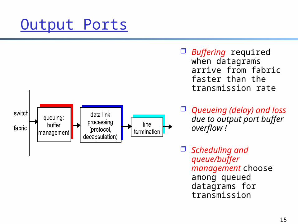
Output Ports
Buffering required when datagrams arrive from fabric faster than the transmission rate
Queueing (delay) and loss due to output port buffer overflow !
Scheduling and queue/buffer management choose among queued datagrams for transmission

Summary
We have covered the basics of the network layer routing and forwarding
There are multiple other topics that we did not cover Multicast/anycast routing QoS slides linked on the schedule page just in case
you want to take a quick look
16

17
Recap: The Hourglass Architecture of the Internet
IP
Ethernet FDDIWireless
TCP UDP
Telnet Email FTP WWW

18
Link Layer: Introduction
Some terminology: hosts and routers are nodes (bridges and switches too)
communication channels that connect adjacent nodes along a communication path are links wired, wireless dedicated, shared
2-PDU is a frame, encapsulates datagram
“link”

19
Link layer: Context
Data-link layer has responsibility of transferring datagram from one node to another node over a link
Datagram transferred by different link protocols over different links, e.g., Ethernet on first link, frame relay on
intermediate links 802.11 on last link
transportation analogy
trip from New Haven to San Francisco taxi: home to union
station train: union station
to JFK plane: JFK to San
Francisco airport shuttle: airport to
hotel

20
Link Layer Services Framing
o encapsulate datagram into frame, adding header, trailer and error detection/correction
Multiplexing/demultiplexingo frame headers to identify src, dest
• different from IP address ! Flow control Link access (interference and quality of service
control) Reliable delivery between adjacent nodes
o we learned how to do this already !o seldom used on low bit error link (fiber, some twisted
pair)o common for wireless links: high error rates

21
Adaptors Communicating
link layer implemented in “adaptor” (aka NIC) Ethernet card,
modem, 802.11 card
adapter is semi-autonomous, implementing link & physical layers
sending side: encapsulates datagram
in a frame adds error checking bits,
rdt, flow control, etc.
receiving side looks for errors, rdt, flow
control, etc extracts datagram,
passes to receiving node
sendingnode
frame
receivingnode
datagram
frame
adapter adapter
link layer protocol

22
LAN/MAC/Physical Address
Each adapter has a unique link layer address (also called MAC address)
• used as address in datalink frames to identify the interface
• 48 bit MAC address (for most types of LANs) burned in the adapter ROM
• MAC address allocation administered by IEEE;manufacturer buys portion of MAC address space (to assure uniqueness)

23
Recall Earlier Routing Discussion
Starting at A, given IP datagram addressed to E:
look up net. address of E, find C
link layer sends datagram to C inside link-layer frame; the dest. address should be C’s MAC address
C’s MACaddr
A’s MACaddr
A’s IPaddr
E’s IPaddr
IP payload
datagramframe
frame source,dest address
datagram source,dest address
223.1.1.1
223.1.1.2
223.1.1.3
223.1.1.4 223.1.2.9
223.1.2.2
223.1.2.1
223.1.3.2223.1.3.1
223.1.3.27
A
BE
C
Question: how to determine MAC address of C knowing C’s IP address?

24
ARP: Address Resolution Protocol
Each IP node (Host, Router) on LAN has ARP table
ARP Table: IP/MAC address mappings for some LAN nodes
< IP address; MAC address; TTL> TTL (Time To Live): time
after which address mapping will be forgotten (typically 20 min)
[yry3@cicada yry3]$ /sbin/arpAddress HWtype HWaddress Flags Mask Ifacezoo-gatew.cs.yale.edu ether AA:00:04:00:20:D4 C eth0artemis.zoo.cs.yale.edu ether 00:06:5B:3F:6E:21 C eth0lab.zoo.cs.yale.edu ether 00:B0:D0:F3:C7:A5 C eth0

25
ARP Protocol
ARP is “plug-and-play”: nodes create their ARP tables without
intervention from net administrator
A broadcast protocol: Source broadcasts query frame, containing
queried IP address • all machines on LAN receive ARP query
destination D receives ARP frame, replies• frame sent to A’s MAC address (unicast)

26
Comparison of IP address and MAC Address
IP address is hierarchical for routing scalability
IP address needs to be globally unique (if no NAT)
IP address depends on IP network to which an interface is attached NOT portable
MAC address is flat
MAC address does not need to be globally unique, but the current assignment ensures uniqueness
MAC address is assigned to a device portable

Outline
Admin Link layer overview Error detection
27

28
Error Detection
D = Data protected by error checking, may include header fieldsED = Error Detection bits (redundancy)
• Error detection not 100% reliable!• a good error detector may miss some errors, but rarely• larger ED field generally yields better detection
‘

29
Cyclic Redundancy Check: Background Widely used in practice, e.g.,
Ethernet, DOCSIS (Cable Modem), FDDI, PKZIP, WinZip, PNG
For a given data D, consider it as a polynomial D(x) consider the string of 0 and 1 as the
coefficients of a polynomial• e.g. consider string 10011 as x4+x+1
addition and subtraction are modular 2, thus the same as xor
Choose generator polynomial G(x) with r+1 bits, where r is called the degree of G(x)

30
Cyclic Redundancy Check: Encode Given data G(x) and D(x), choose R(x)
with r bits, such that D(x)xr+R(x) is exactly divisible by G(x)
The bits correspond to D(x)xr+R(x) are sent to the receiver
+x

31
Cyclic Redundancy Check: Decode
Since G(x) is global, when the receiver receives the transmission T’(x), it divides T’(x) by G(x) if non-zero remainder: error detected! if zero remainder, assumes no error
Encode:CRC(G)
DT = D(x)xr+R(x) T’
check

32
CRC: Steps and an Example
Suppose the degree of G(x) is r
Append r zero to D(x), i.e. consider D(x)xr
Divide D(x)xr by G(x). Let R(x) denote the reminder
Send <D, R> to the receiver

33
The Power of CRC Let T(x) denote D(x)xr+R(x), and E(x) the polynomial of the
error bits the received signal is T’(x) = T(x)+E(x)
Since T(x) is divisible by G(x), we only need to consider if E(x) is divisible by G(x)
Encode:CRC(G)
DT = D(x)xr+R(x) T’
check

34
The Power of CRC
Detect a single-bit error: E(x) = xi
if G(x) contains two or more terms, E(x) is not divisible by G(x)
Detect an odd number of errors: E(x) has an odd number of terms: lemma: if E(x) has an odd number of terms, E(x) cannot
be divisible by (x+1)• suppose E(x) = (x+1)F(x), let x=1, the left hand will be 1, while
the right hand will be 0 thus if G(x) contains x+1 as a factor, E(x) will not be
divided by G(x)
Many more errors can be detected by designing the right G(x)

35
Example G(x)
16 bits CRC: CRC-16: x16+x15+x2+1,
CRC-CCITT: x16+x12+x5+1 both can catch
• all single or double bit errors• all odd number of bit errors• all burst errors of length 16
or less• >99.99% of the 17 or 18 bits
burst errors
CRC-16 hardware implementationUsing shift and XOR registers
http://en.wikipedia.org/wiki/CRC-32#Implementation

36
Example G(x) 32 bits CRC:
CRC32: x32 + x26 + x23 + x22 + x16 + x12 + x11 + x10 + x8 + x7 + x5 + x4 + x2 + x + 1
used by Ethernet, FDDI, PKZIP, WinZip, and PNG GSM phones
For more details see the link below and further links it contains: http://en.wikipedia.org/wiki/Cyclic_redundancy_check
.

Outline
Admin Link layer overview Error detection Link access
37

38
Multiple Access Links and Protocols
Two types of “links”: point-to-point
e.g., a leased dedicated line, PPP for dial-up access
broadcast (shared wire or medium) traditional Ethernet 802.11 wireless LAN satellite

39
Multiple Access Protocols Single shared broadcast channel
thus, if two or more simultaneous transmissions by nodes, due to interference, only one node can send successfully at a time (see CDMA later for an exception)
multiple access protocol Protocol that determines how nodes share
channel, i.e., determines when nodes can transmit Communication about channel sharing must use
channel itself !
Discussion: properties of an ideal multiple access protocol.

40
Ideal Mulitple Access Protocol
Broadcast channel of rate R bps- Efficiency: when one node wants to transmit, it
can send at rate R
- Fairness: when N nodes want to transmit, each can send at average rate R/N
- Decentralized: no special node to coordinate transmissions no synchronization of clocks
- Simple

41
MAC Protocols: a Taxonomy
Goals efficient, fair, decentralized, simple
Three broad classes: channel partitioning
divide channel into smaller “pieces” (time slot, frequency, code)
Non-partitioning random access
• allow collisions “taking-turns”
• a token coordinates shared access to avoid collisions

42
Outline
Admin. and recap Link layer overview Error detection and correction Media access control (MAC) protocols
channel partitioning

43
Channel Partitioning: TDMA
TDMA: time division multiple access Access to channel in "rounds" Each station gets fixed length slot (length =
pkt trans time) in each round Unused slots go idle Example: 6-station LAN, 1,3,4 have pkt, slots
2,5,6 idle

44
Channel Partitioning: FDMA
FDMA: frequency division multiple access Channel spectrum divided into frequency bands Each station assigned fixed frequency band Unused transmission time in frequency bands go
idle Example: 6-station LAN, 1,3,4 have pkt,
frequency bands 2,5,6 idle
frequ
ency
bands time
5
1
4
3
2
6

45
1 2 3 4 5 6 7 8
935-960 MHz124 channels (200 kHz)downlink
890-915 MHz124 channels (200 kHz)uplink
frequ
ency
time
GSM TDMA frame
GSM time-slot (normal burst)
4.615 ms
546.5 µs577 µs
tail user data TrainingSguardspace S user data tail
guardspace
3 bits 57 bits 26 bits 57 bits1 1 3
GSM - TDMA/FDMA
S: indicates data or control

46
Channel Partitioning: CDMA
CDMA (Code Division Multiple Access) Used mostly in wireless broadcast channels
(cellular, satellite, etc) A spread-spectrum technique
Example: Sprint , Verizon 3G802.11
History: http://people.seas.harvard.edu/~jones/cscie129/nu_lectures/lecture7/hedy/lemarr.htm

47
CDMA: Encoding
All users share same frequency, but each user m has its own unique “chipping” sequence (i.e., code) cm to encode data, i.e., code set partitioning e.g. cm = 1 1 1 -1 1 -1 -1 -1
Assume original data are represented by 1 and -1
Encoded signal = (original data) modulated by (chipping sequence) assume cm = 1 1 1 -1 1 -1 -1 -1
if data is d, send d cm, • if data d is 1, send cm
• if data d is -1 send -cm

CDMA: Encoding
48
user data d(t)
chipping sequence c(t)
resultingsignal
1 -1
-1 1 1 -1 1 -1 1 -11 -1 -1 1 11
X
=
tb
tc
tb: bit periodtc: chip period
-1 1 1 -1 -1 1 -1 11 -1 1 -1 -11

49
CDMA: Decoding
Inner-product (summation of bit-by-bit product) of encoded signal and chipping sequence if inner-product > 0, the data is 1; else -1

50
CDMA Encode/Decode
Code of user m cm: 1 1 1 -1 1 -1 -1 -1
- The number of bitsof each chipping sequence is M
Encode
Decode

51
CDMA: Deal with Multiple-User Interference
Two codes Ci and Cj are orthogonal, if , where we use “.” to denote inner
product, e.g.
If codes are orthogonal, multiple users can “coexist” and transmit simultaneously with minimal interference:
iiij
jj cdccd )(
0 ij cc
C1: 1 1 1 -1 1 -1 -1 -1 C2: 1 -1 1 1 1 -1 1 1-----------------------------------------C1 . C2 = 1 +(-1) + 1 + (-1) +1 + 1+ (-1)+(-1)=0
Analogy: Speak in different languages!

52
CDMA: Two-Sender Interference
Code 1: 1 1 1 -1 1 -1 -1 -1Code 2: 1 -1 1 1 1 -1 1 1

Discussions
Advantages of channel partitioning
Problems of channel partitioning
53

Backup Slides
54

55
Backup: IP Multicast

56
IP Fragmentation & Reassembly Network links have MTU
(max.transfer size) - largest possible link-level frame. different link types,
different MTUs, e.g. Ethernet MTU is 1500 bytes
Large IP datagram divided (“fragmented”) one datagram
becomes several datagrams
“reassembled” only at final destination
IP header bits used to identify, order related fragments
fragmentation: in: one large datagramout: 3 smaller datagrams
reassembly

57
IP Fragmentation and Reassembly
ID=x
offset=0
fragflag=0
length=4000
ID=x
offset=0
fragflag=1
length=1500
ID=x
offset=1480
fragflag=1
length=1500
ID=x
offset=2960
fragflag=0
length=1040
One large datagram becomesseveral smaller datagrams
Example 4000 byte
datagram MTU = 1500
bytes

58
IP Multicast: Service Model
Multicast group concept: use of indirection A group is identified by a location-independent
logical address (class D IP address: prefix 1110) Open group model
Anyone can send packets to the “logical” group address Anyone can join a group and receive packets
Normal, best-effort delivery semantics of IP
128.119.40.186
128.59.16.12
128.34.108.63
128.34.108.60
multicast group
226.17.30.197
Needed: infrastructure to deliver mcast-addressed datagrams to all hosts that have joined that multicast group

59
Multicast Across LANs
shared tree source-based trees
Goal: find a tree (or trees) connecting routers having local mcast group members source-based: different tree from sender to each receiver
– Distance-vector multicast routing protocol (DVMRP)– Protocol-independent multicast-dense mode (PIM-DM)
shared-tree: same tree used by all group members– Core-Based Tree (CBT)– Protocol-independent multicast-sparse mode (PIM-SM)

60
Source Tree: Reverse Path Flooding (RPF)
A router x forwards a packet from source (S) iff it arrives via neighbor y, and y is on the shortest path from x back to S
A packet is replicated to all but the incoming interface
xxyy
tt
SS
a
zz
1
1
1
1
1

61
Reverse Path Forwarding: Improvement Basic idea: forward a packet from S only
on child links for S A child link of router x for source S
a link that has x as parent on the shortest path from thelink to S
a child x notifies its parent y(through the routing protocol)that it has selected y as itsparent
xxyy
tt
SS
a
zz

62
Reverse Path Forwarding: Pruning No need to forward datagrams down
subtree with no mcast group members
“prune” msgs sent upstream by router with no downstream group members
R1
R2
R3
R4
R5
R6 R7
router with attachedgroup member
router with no attachedgroup member
prune message
LEGENDS: source
links with multicastforwarding
P
P
P

63
Pruning
Prune (Source, Group) at a leaf router if no members send No-Membership Report (NMR) up tree
If all children of router R prune (S,G) propagate prune for (S,G) to its parent
What do you do when a member of a group (re)joins? send a Graft message to upstream parent
How to deal with failures? prune dropped flow is reinstated down stream routers re-prune
Note: again a soft-state approach

64
Implementation of Source Trees in the Internet
Multicast OSFP (MOSFP) Membership is part of the link state distribution;
calculate source specific, pre-pruned trees
Reverse Path Forwarding Distance Vector Multicast Routing Protocol (DVMRP) Protocol Independent Multicast – Dense Mode (PIM-DM)
• very similar to DVMRP
Difference: PIM uses any unicast routing algorithm to determine the path from a router to the source; DVMRP uses distance vector
Question: the state requirement of Reverse Path Forwarding

65
Building a Shared Tree
Steiner Tree: minimum cost tree connecting all routerswith attached group members
A Steiner tree is not a spanning tree because you do not need to connect all nodes in the network
Problem is NP-hard Excellent heuristics exists Not used in practice:
computational complexity information about entire network needed monolithic: rerun whenever a router needs to join/leave

66
Center (Core) based Shared Tree
Single delivery tree shared by all One router identified as “center” of tree Tree construction is receiver-based
edge router sends unicast join-msg addressed to center router
join-msg “processed” by intermediate routers and forwarded towards center
join-msg either hits existing tree branch for this center, or arrives at center
path taken by join-msg becomes new branch of tree for this router
A sender unicasts a packet to center The packet is distributed on the tree when it hits the
tree

67
Example: M3 Joins
Group members: M1, M2
core
M1
M2 M3
shared tree
S1join message
Discussion: what is property of the constructed tree?

68
Example: M1 Sends Data Group members: M1, M2, M3 M1 sends data
core
M1
M2 M3
control (join) messagesdata S1

69
Shared Tree Protocols in the Internet
Core Based Tree Protocol Independent Multicast (PIM)
Sparse mode The catch: how do you know the center?
session announcement

70
Mbone: Tunneling
Q: How to connect “islands” of multicast routers in a “sea” of unicast routers?
mcast datagram encapsulated inside “normal” (non-multicast-addressed) datagram
normal IP datagram sent thru “tunnel” via regular IP unicast to receiving mcast router
receiving mcast router unencapsulates to get mcast datagram
physical topology logical topology