Embed Size (px)
Citation preview

1
1. Introduction
The common features of the EX-9033/33P,EX-9036/36P,
EX-9015/15-M, and EX-9033-M/33P-M,EX-9036-M/36P-M
modules are as follows: 1. 3000V DC inter-module isolation
2. 24-bit sigma-delta ADC to provide excellent accuracy
3. Direct RTD (resistance temperature detector) connection
4. Off-set value setting by Utility of EX-9000 for individual
channel
5. Support 2/3/4 wire(see wire connection on CD of EX9000
series or topsccc.com)
6. Break line detection
7. Modbus function
The EX-9033/33-M is a 3-channel RTD input module.
The EX-9033P/33P-M is a 3-channel RTD input module
with individual channel configuration.
The EX-9036/36-M is a 6-channel RTD input module.
The EX-9036P/36P-M is a 6-channel RTD input module.
with individual channel configuration.
EX-9015/15-M is a 6-channel RTD input module.
with individual channel configuration.
Supported RTD types are as follows: 1. Platinum, 100 Ohms at 0°C, α= 0.00385 2. Platinum, 100 Ohms at 0°C, α= 0.003916 3. Platinum, 1000 Ohms at 0°C, α= 0.00385 4.Nickel, 120 Ohms at 0°C, α= 0.00672 5. Copper, 100 Ohms at 0°C, α= 0.00421 6. Copper, 1000 Ohms at 0°C, α= 0.00421 7. Copper, 100 Ohms at 25°C, α= 0.00427 8. Copper, 50 Ohms at 0°C 9. Nickel, 100 Ohms at 0°C

2

3
4
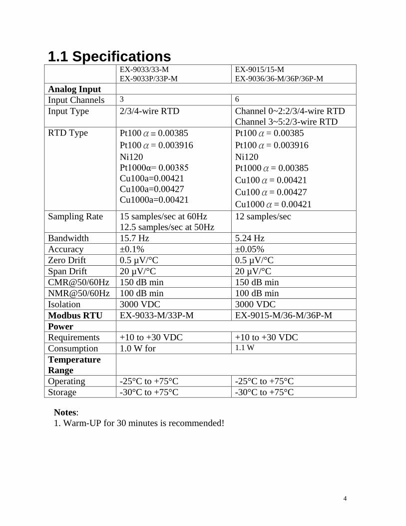
1.1 Specifications
EX-9033/33-M
EX-9033P/33P-M
EX-9015/15-M
EX-9036/36-M/36P/36P-M
Analog Input
Input Channels 3 6
Input Type 2/3/4-wire RTD Channel 0~2:2/3/4-wire RTD
Channel 3~5:2/3-wire RTD
RTD Type Pt100α= 0.00385
Pt100α= 0.003916
Ni120
Pt1000α= 0.00385
Cu100a=0.00421
Cu100a=0.00427
Cu1000a=0.00421
Pt100α= 0.00385
Pt100α= 0.003916
Ni120
Pt1000α= 0.00385
Cu100α= 0.00421
Cu100α= 0.00427
Cu1000α= 0.00421
Sampling Rate 15 samples/sec at 60Hz
12.5 samples/sec at 50Hz
12 samples/sec
Bandwidth 15.7 Hz 5.24 Hz
Accuracy ±0.1% ±0.05%
Zero Drift 0.5 µV/°C 0.5 µV/°C
Span Drift 20 µV/°C 20 µV/°C
CMR@50/60Hz 150 dB min 150 dB min
NMR@50/60Hz 100 dB min 100 dB min
Isolation 3000 VDC 3000 VDC
Modbus RTU EX-9033-M/33P-M EX-9015-M/36-M/36P-M
Power
Requirements +10 to +30 VDC +10 to +30 VDC
Consumption 1.0 W for 1.1 W
Temperature
Range
Operating -25°C to +75°C -25°C to +75°C
Storage -30°C to +75°C -30°C to +75°C
Notes:
1. Warm-UP for 30 minutes is recommended!

5
1.2 Wire connection
1.2.1 Block Diagrams
Led
Display
EEPROM
Single
Controller
RS485
Interface
Power
Supply
+5V
RTD1+
A.GND
EX9015/33/36
Data+ Data-
+Vs GND
Photo-Isolation
ADC
COM
RTD5-
RTD1-
COM
RTD5+
MUX
6
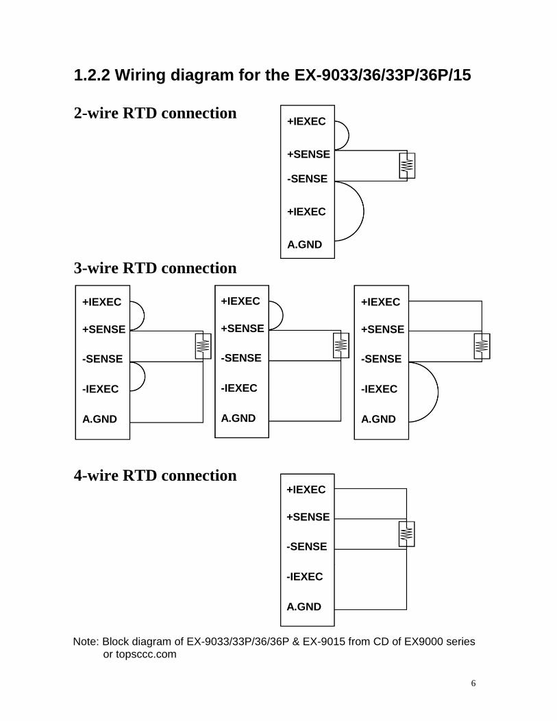
1.2.2 Wiring diagram for the EX-9033/36/33P/36P/15
2-wire RTD connection
3-wire RTD connection
4-wire RTD connection
Note: Block diagram of EX-9033/33P/36/36P & EX-9015 from CD of EX9000 series
or topsccc.com
+IEXEC
+SENSE
-SENSE
+IEXEC
A.GND
+IEXEC
+SENSE
-SENSE
-IEXEC
A.GND
+IEXEC
+SENSE
-SENSE
-IEXEC
A.GND
+IEXEC
+SENSE
-SENSE
-IEXEC
A.GND
+IEXEC
+SENSE
-SENSE
-IEXEC
A.GND

7
1.2.3 Wiring Recommendations
1.For the EX-9033/36 and EX-9033P/36P,the wires of a
channel should be shielded and the shielding should
be connected to the A.GND terminal of the channel.
2.For the EX-9015, it is recommended to
use shielded wire and connect the shielding to the
IEXEC+ terminal of the channel.
3.For RS-485, use insulated and twisted pair 24 AWG wire,
e.g. Belden 9841.
4.Use 26-12 AWG wire for signal connections.

8
1.3 Default Settings Default settings for the EX-9033/33P/36/36P & EX9015
modules are as follows:
. Module Address: 01
. RTD Type: Type 20, Pt100, -100°C to 100°C
. Baud Rate: 9600 bps
. Checksum disabled
. Engineering unit format
. Filter set at 60Hz rejection
Default settings for the EX-9033-M/33P-M/36-M/36P-M &
EX9015-M modules are as follows:
. Protocol: Modbus RTU
. Module Address: 01
. RTD Type: Type 20, Pt100, -100°C to 100°C
. Baud Rate: 9600 bps
. Filter set at 60Hz rejection

9
1.4 Calibration(Warning: Pls don't calibrate before you
really understand.)
Calibration sequence:
1. Install zero calibration resistor.
2. Warm up the module for at least 30 minutes.
3. Set the type code to the type you wish to calibrate.
4. Enable calibration.
5. Perform zero calibration command.
6. Install span calibration resistor.
7. Perform span calibration command.
8. Repeat steps 4 to 7 three times.
Notes: 1. Use the 2-wire RTD connection to connect the calibration
resistor.
2. For the EX-9033/36,connect the calibration resistor to channel 0.
3. For the EX-9015, EX-9033P/36P each channel should be
calibrated separately and only the channel being calibrated should
be enabled during calibration.
4. Calibration resistors are shown on the follows.
5. The EX-9000 series modules must be switched to the Normal
protocol mode before calibrating.
10
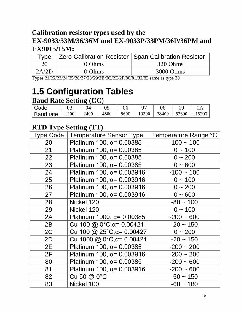
Calibration resistor types used by the
EX-9033/33M/36/36M and EX-9033P/33PM/36P/36PM and
EX9015/15M: Type Zero Calibration Resistor Span Calibration Resistor
20 0 Ohms 320 Ohms
2A/2D 0 Ohms 3000 Ohms
Types 21/22/23/24/25/26/27/28/29/2B/2C/2E/2F/80/81/82/83 same as type 20
1.5 Configuration Tables Baud Rate Setting (CC)
Code 03 04 05 06 07 08 09 0A
Baud rate 1200 2400 4800 9600 19200 38400 57600 115200
RTD Type Setting (TT)
Type Code Temperature Sensor Type Temperature Range °C
20 Platinum 100, α= 0.00385 -100 ~ 100
21 Platinum 100, α= 0.00385 0 ~ 100
22 Platinum 100, α= 0.00385 0 ~ 200
23 Platinum 100, α= 0.00385 0 ~ 600
24 Platinum 100, α= 0.003916 -100 ~ 100
25 Platinum 100, α= 0.003916 0 ~ 100
26 Platinum 100, α= 0.003916 0 ~ 200
27 Platinum 100, α= 0.003916 0 ~ 600
28 Nickel 120 -80 ~ 100
29 Nickel 120 0 ~ 100
2A Platinum 1000, α= 0.00385 -200 ~ 600
2B Cu 100 @ 0°C,α= 0.00421 -20 ~ 150
2C Cu 100 @ 25°C,α= 0.00427 0 ~ 200
2D Cu 1000 @ 0°C,α= 0.00421 -20 ~ 150
2E Platinum 100, α= 0.00385 -200 ~ 200
2F Platinum 100, α= 0.003916 -200 ~ 200
80 Platinum 100, α= 0.00385 -200 ~ 600
81 Platinum 100, α= 0.003916 -200 ~ 600
82 Cu 50 @ 0°C -50 ~ 150
83 Nickel 100 -60 ~ 180

11
Data Format Setting (FF)
7 6 5 4 3 2 1 0
FS CS reserved DF
Key Description
DF Data format
00: Engineering unit
01: % of FSR (full scale range)
10: 2’s complement hexadecimal
11: Ohms
CS Checksum setting
0: Disabled
1: Enabled
FS Filter setting
0: 60Hz rejection
1: 50Hz rejection
Note: The reserved bits should be zero.
.
12
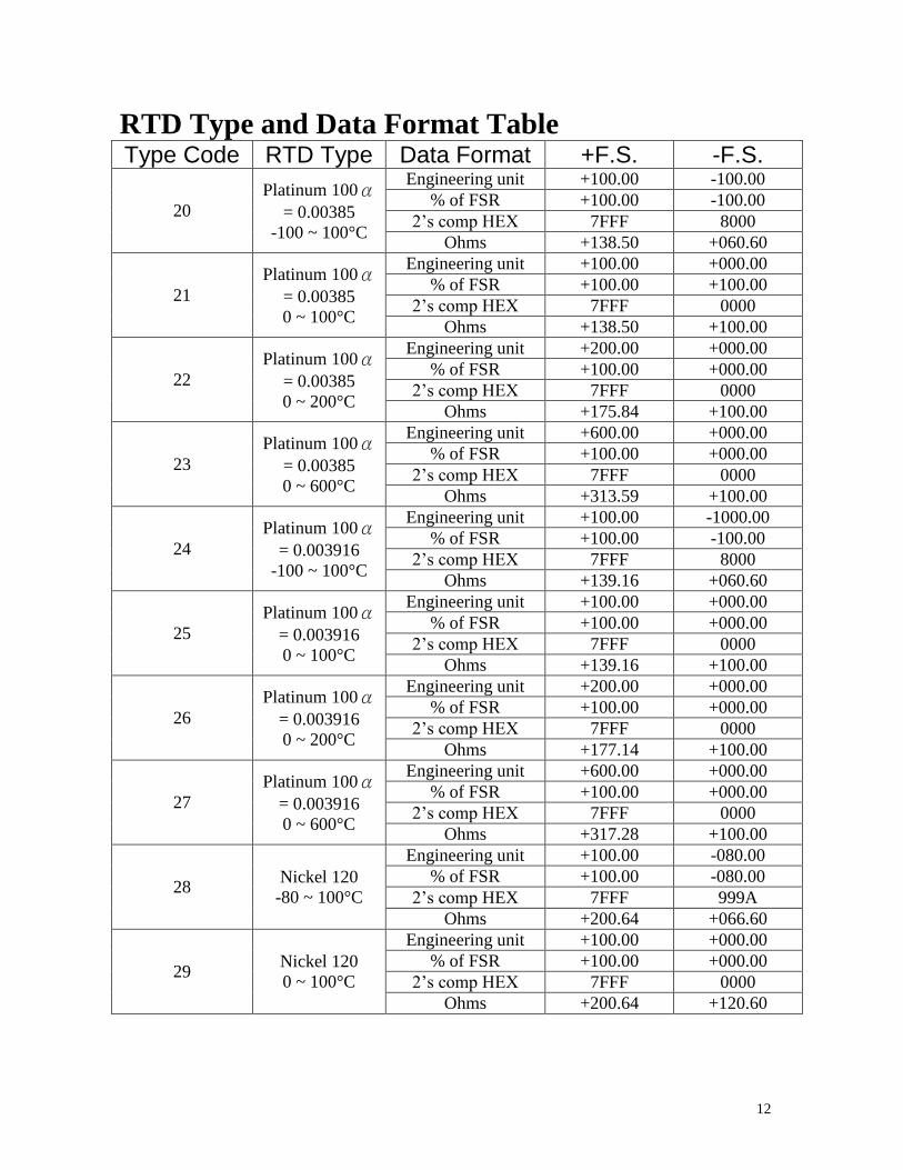
RTD Type and Data Format Table
Type Code RTD Type Data Format +F.S. -F.S.
20
Platinum 100α= 0.00385
-100 ~ 100°C
Engineering unit +100.00 -100.00
% of FSR +100.00 -100.00
2’s comp HEX 7FFF 8000
Ohms +138.50 +060.60
21
Platinum 100α= 0.00385
0 ~ 100°C
Engineering unit +100.00 +000.00
% of FSR +100.00 +100.00
2’s comp HEX 7FFF 0000
Ohms +138.50 +100.00
22
Platinum 100α= 0.00385
0 ~ 200°C
Engineering unit +200.00 +000.00
% of FSR +100.00 +000.00
2’s comp HEX 7FFF 0000
Ohms +175.84 +100.00
23
Platinum 100α= 0.00385
0 ~ 600°C
Engineering unit +600.00 +000.00
% of FSR +100.00 +000.00
2’s comp HEX 7FFF 0000
Ohms +313.59 +100.00
24
Platinum 100α= 0.003916
-100 ~ 100°C
Engineering unit +100.00 -1000.00
% of FSR +100.00 -100.00
2’s comp HEX 7FFF 8000
Ohms +139.16 +060.60
25
Platinum 100α= 0.003916
0 ~ 100°C
Engineering unit +100.00 +000.00
% of FSR +100.00 +000.00
2’s comp HEX 7FFF 0000
Ohms +139.16 +100.00
26
Platinum 100α= 0.003916
0 ~ 200°C
Engineering unit +200.00 +000.00
% of FSR +100.00 +000.00
2’s comp HEX 7FFF 0000
Ohms +177.14 +100.00
27
Platinum 100α= 0.003916
0 ~ 600°C
Engineering unit +600.00 +000.00
% of FSR +100.00 +000.00
2’s comp HEX 7FFF 0000
Ohms +317.28 +100.00
28 Nickel 120
-80 ~ 100°C
Engineering unit +100.00 -080.00
% of FSR +100.00 -080.00
2’s comp HEX 7FFF 999A
Ohms +200.64 +066.60
29 Nickel 120
0 ~ 100°C
Engineering unit +100.00 +000.00
% of FSR +100.00 +000.00
2’s comp HEX 7FFF 0000
Ohms +200.64 +120.60

13
Type Code RTD Type Data Format +F.S. -F.S.
2A
Platinum 1000
α= 0.00385
-200 ~ 600°C
Engineering unit +600.00 -200.00
% of FSR +100.00 -033.33
2’s comp HEX 7FFF D556
Ohms +3137.1 +0185.2
2B
Cu 100
α= 0.00421
-20 ~ 150°C
Engineering unit +150.00 -020.00
% of FSR +100.00 -013.33
2’s comp HEX 7FFF EEEF
Ohms +163.17 +091.56
2C
Cu 100
α= 0.00427
0 ~ 200°C
Engineering unit +200.00 +000.00
% of FSR +100.00 +000.00
2’s comp HEX 7FFF 0000
Ohms +167.75 +090.34
2D
Cu 100
α= 0.00421
-20 ~ 150°C
Engineering unit +150.00 -020.00
% of FSR +100.00 -013.33
2’s comp HEX 7FFF EEEF
Ohms +1631.7 +0915.6
2E
Platinum 100α= 0.00385
-200 ~ 200°C
Engineering unit +200.00 -200.00
% of FSR +100.00 -100.00
2’s comp HEX 7FFF 8000
Ohms +175.84 +018.49
2F
Platinum 100α
= 0.003916
-200 ~ 200°C
Engineering unit +200.00 -200.00
% of FSR +100.00 -100.00
2’s comp HEX 7FFF 8000
Ohms +177.14 +017.14
80
Platinum 100
α= 0.00385
-200 ~ 600°C
Engineering unit +600.00 -200.00
% of FSR +100.00 -033.33
2’s comp HEX 7FFF D556
Ohms +313.59 +018.49
81
Platinum 100
α= 0.003916
-200 ~ 600°C
Engineering unit +600.00 -200.00
% of FSR +100.00 -033.33
2’s comp HEX 7FFF D556
Ohms +317.28 +017.14
82 Cu 50
-50 ~ 150°C
Engineering unit +150.00 -050.00
% of FSR +100.00 -033.33
2’s comp HEX 7FFF D556
Ohms +082.13 +039.24
83 Nickel 100
-60 ~ 180°C
Engineering unit +180.00 -060.00
% of FSR +100.00 -033.33
2’s comp HEX 7FFF D556
Ohms +223.10 +069.50

14
RTD Over Range/Under Range Reading
Over Range Under Range
Engineering Unit +9999.9 -9999.9
% of FSR +999.99 -999.99
2’s Complement HEX 7FFF 8000
RTD Over Range/Under Range Reading for the
EX-9015M and EX-9033M/33PM/36M with Modbus
RTU Protocol
Over Range Under Range
7FFFh 8000h

15
2.1 %AANNTTCCFF
Description: Set Module Configuration of an analog input
Module.
Syntax: %AANNTTCCFF[CHK](cr)
%
AA
NN
TT
CC
FF
Response: Valid Command: !AA
Invalid Command: ?AA
Example:
Command :%0102240600 Receive:!02
Set module address 01 to 02, return Success.
a delimiter character
address of setting/response module(00 to FF)
new address for setting/response module(00 to FF)
new type code for EX9033/33M/36/36M
parity type of EX9015/15M
EX9033P/33PM/36P/36PM fix to 00
EX9033P/33PM/36P/36PM/15/15M are use the
$AA7CiRrr to set the type of each channel.(P28)
baud rate code, The INIT* terminal must be connected
to GND terminal in order to change Baud Rates.(P10)
used to set the data format, checksum, and filter
settings. The INIT* terminal must be connected to GND
terminal in order to change the checksum setting. (P11)
00 No parity
10 Even parity
11 Odd parity

16
2.2 #**
Description: Synchronized Sampling
Syntax: #**[CHK](cr)
# delimiter character
** synchronized sampling command
Response: No response
Example:
Command: #** No response
Send synchronized sampling command to all modules.
Command: $014 Receive:
>011+051.23+041.53+072.34
Read synchronized data from address 01, return S=1, first
read and data is +051.23+041.53+072.34
Command: $014 Receive:
>010+051.23+041.53+072.34
Read synchronized data from address 02, return S=0, have
readed and data is +051.23+041.53+072.34
17
2.3 #AA
Description: Read Analog Input
Syntax:#AA[CHK](cr)
# delimiter character
AA address of reading/response module(00 to FF)
Response: Valid Command: >(Data)
(Data) analog input value for its format while use #AA
command to EX9033/36/15, the data is the
combination for each channel respectively.
Example : Command: #04
Receive:>+051.23+041.53+072.34-023.56+100.00-
051.33
The module address 04 is EX9036/15. Read address 04 for
getting data of all 6 channels.

18
2.4 #AAN
Description : Read Analog Input from channel N
Syntax : #AAN[CHK](cr)
# delimiter character
AA address of reading/response module(00 to FF)
N channel to read, from 0 to 3/6
Response: Valid Command: >(Data)
Invalid Command: ?AA
(Data) analog input value for its format
Example : Command : #032 Receive : >+025.13
Read address 03 channel 2, get data successfully.
Command : #029 Receive : ?02
Read address 02 channel 9, return error channel number.

19
2.5 $AA0 (For EX9033/33M/36/36M)
Description: Perform Zero Calibration Syntax: $AA0[CHK](cr)
$ delimiter character
AA address of setting/response module (00 to FF)
0 command for performing zero calibration
Response: Valid Command: !AA
Invalid Command: ?AA
Example : Command : $010 Receive : !01
Perform address 01 zero calibration on channel 0, return
success.
Command : $020 Receive : ?02
Perform address 02 zero calibration on channel 2 , return not
enable calibration before perform calibration command.
Warning: Pls don't calibrate before you really understand.

20
2.6 $AA1 (For EX9033/33M/36/36M)
Description: Perform Span Calibration
Syntax: $AA1[CHK](cr)
$ delimiter character
AA address of setting/response module (00 to FF)
1 command for performing span calibration
Response: Valid Command: !AA Invalid Command: ?AA
Example: Command: $011 Receive: !01
Perform address 01 span calibration on channel 0, return
success.
Command: $021 Receive: ?02
Perform address 02 span calibration on channel 2, return not
enable calibration before perform calibration command.
Warning: Pls don't calibrate before you really understand.

21
2.7 $AA0Ci (For EX9033P/33PM/15/15M/36P/36PM)
Description: Perform zero calibration on the specified
channel.
Syntax:$AA0Ci[CHK](cr)
$ delimiter character
AA address of setting/response module (00 to FF)
0 command for the zero calibration
Ci specifies the channel to be calibrated
(EX9033P/33PM: i=0~2, EX9036P/15/15M: i=0~5)
Response: Valid Command: !AA
Invalid Command: ?AA
Example: Command :$010C0 Receive : !01
Perform address 01 zero calibration on channel 0, return
success.
Command : $020C2 Receive : ?02
Perform address 02 zero calibration on channel 2, return not
enable calibration before perform calibration command.
Note: This command must be sent before the “span
calibration” command, $AA1Ci, is used.

22
2.8 $AA1Ci (For EX9033P/33PM/15/15M/36P/36PM)
Description: Perform span calibration on the specified
channel.
Syntax:$AA1Ci[CHK](cr)
$ delimiter character
AA address of setting/response module (00 to FF)
1 command for performing span calibration
Ci specifies the channel to be calibrated
(EX9033P/33PM: i=0~2, EX9036P/15/15M: i=0~5)
Response: Valid Command: !AA
Invalid Command: ?AA
Example: Command: $011C0 Receive: !01
Perform address 01 span calibration on channel 0, return
success.
Command: $021C2 Receive: ?02
Perform address 02 span calibration on channel 2, return not
enable calibration before perform calibration command.
23
2.9 $AA2
Description: Read configuration. Syntax:$AA2[CHK](cr)
$ delimiter character
AA address of reading/response module(00 to FF)
2 command for read configuration
Response: Valid Command: !AATTCCFF
Invalid Command: ?AA
TT
CC
FF
Example: Command: $012 Receive: !01200600
Read the configuration of module 01.
Note: check configuration Tables
type code of the module
baud Rate code of the module
data format, checksum settings and filter
settings of the module

24
2.10 $AA4
Description: Reads the synchronized data
Syntax:$AA4[CHK](cr)
$ delimiter character
AA address of reading/response module(00 to FF)
4 command to read the synchronized data
Response: Valid Command: >AAS(Data)
Invalid Command: ?AA
S status of synchronized data, 1=first read, 0=been
readed
(Data) synchronized value
Example: Command: $014 Receive: ?01
Read address 01 synchronized data, return no data available.
Command: #** Receive: no response
Send synchronized sampling to all modules.
Command: $014
Receive:>011+051.23+041.53+072.34
Read address 01 synchronized data, return S=1, first read,
and synchronized data +025.56

25
2.11 $AA5
Description: Read Reset Status
Syntax:$AA5[CHK](cr)
$ delimiter character
AA address of reading/response module(00 to FF)
5 command for read reset status
Response: Valid Command: !AAS
Invalid Command: ?AA
S reset status, 1=the module is been reset, 0=the module
is not been rested
Example: Command: $ 015 Receive: !011
Read address 01 reset status, return module is been reset
Command: $ 015 Receive: !010
Read address 01 reset status, return no reset occurred.

26
2.12 $AA5VV
Description: Set Channel Enable
Syntax:$AA5VV[CHK](cr)
$ delimiter character
AA address of setting/response module (00 to FF)
5 command for set channel enable
VV channel enable/disable, 00 is all disabled and FF is all
enabled.
Response: Valid Command: !AA
Invalid Command: ?AA
Example: Command :$0152A Receive : !01
Set address 01 to enable channel 1,3,5 and disable channel
0,2,5 return success.
Command : $016 Receive : !012A
Read address 01 channel status, return channel 1,3,5 are
enabled and channel 0,2,4 are disabled.
27
2.13 $AA6
Description: Read Channel Status
Syntax: $AA6[CHK](cr) $ delimiter character
AA address of reading/response module (00 to FF)
6 command for read channel status
Response: Valid Command: !AAVV
Invalid Command: ?AA
VV channel enable/disable, 00 is all disabled and FF is all
enabled.
Example: Command :$0152A Receive : !01
Set address 01 to enable channel 1,3,5 and disable channel
0,2,4 return success.
Command : $016 Receive : !012A
Reads Read address 01 channel status, return channel 1,3,5
are enabled and channel 0,2,4 are disabled.
28
2.14 $AA7CiRrr (For EX9033P/33PM/15/15M/36P/36PM)
Description: Sets the type code of a channel.
Syntax:$AA7CiRrr[CHK](cr)
$ delimiter character
AA address of setting/response module(00 to FF)
7 set the channel range code
Ci i specifies the input channel to be set
(EX9033P/33PM: i=0~2, EX9036P/15/15M: i=0~5)
Rrr rr represents the type code of the channel to be
set.
Response: Valid comma nd: !AA
Invalid command: ?AA
Example: Command: $017C0R20 Receive: !01
Sets the type code for channel 0 of module 01 to be
20 (PT100, -100 ~ +100°C) and the module returns a
valid response.
Command: $027C5R28 Receive: !02
Sets the type code for channel 5 of module 02 to be
28 (Ni120, -80 ~ +100°C) and the module returns a
valid response.
Command: $037C1R40 Receive: ?03
Sets the type code for channel 1 of module 03 to be
40. The module returns an invalid response because
the type code is invalid.
29
2.15 $AA8Ci (ForEX9033P/33PM/15/15M/36P/36PM)
Description:Reads the type code information of a channel.
Syntax:$AA8Ci[CHK](cr)
$ delimiter character
AA address of reading/response module(00 to FF)
8 read the type code of a channel
Ci specifies which channel to be access for the type
code
(EX9033P/33PM: i=0~2, EX9036PM/15/15M: i=0~5)
Response: Valid command: !AACiRrr
Invalid command: ?AA
Ci specifies which channel to be access for the type
code
(EX9033P/33PM: i=0~2, EX9036P/15/15M: i=0~5)
Rrr rr repesents the type code of the channel to be read
Example: Command: $018C0 Receive: !01C0R20
Reads the type(input range) of channel 0 of module 01 to be
20 (PT100, -100 ~ +100°C).

30
2.16 $AAB
Description: Diagnoses the analog inputs for over-range,
under-range,and wire opening conditions.
Syntax:$AAB[CHK](cr)
$ delimiter character
AA address of reading/response module (00 to FF)
B diagnose the analog inputs
Response: Valid command: !AANN
Invalid command: ?AA
NN represents the diagnostic results of all the
analog input channels (00 to FF) where bit 0
relat to channel 0, bit 1 relat to channel 1,
etc. When the bit is 1 and the channel is enabled
and it is in either overrange,under-range or wire
opening condition. If the bit is 0 and the channel is
disabled or normal.
Example: Command: $01B Receive: !0101
Diagnoses the analog inputs of module 01. The module
returns a valid response that channel 0 is in either
over-range, under-range or wire opening condition.
31
2.17 $AAF
Description: Read Firmware Version
Syntax:$AAF[CHK](cr)
$ delimiter character
AA address of reading/response module(00 to FF)
F command for read firmware version
Response: Valid command: !AA(Data)
Invalid command: ?AA
(Data) Firmware version of module
Example: Command : $01F Receive : !01P1.1
Read address 01 firmware version, return version P1.1.
Command : $01F Receive : !01M1.1
Read address 01 firmware version, return version M1.1

32
2.18 $AAM
Description:Read Module Name
Syntax:$AAM[CHK](cr)
$ delimiter character
AA address of reading/response module(00 to FF)
M command for read module name
Response: Valid command: !AA(Data)
Invalid command: ?AA
(Data) Name of module
Example: Command : $01M Receive : !019033
Read address 01 module name, return name 9033.
Command : $03M Receive : !039036
Read address 03 module name, return name 9036

33
2.19 $AAP (For EX9033M/33PM/15M/36M/36PM)
Description:Read protocol information of Module
Syntax:$AAP[CHK](cr)
$ delimiter character
AA address of reading/response module(00 to FF)
P command for read protocol information of module
Response: Valid command: !AAS
Invalid command: ?AA
S The protocol supported by the module
10: the protocol set in EEPROM is Normal mode
11: the protocol set in EEPROM is ModbusRTU mode
Example: Command: $01P Response: !0110
Reads the communication protocol of module 01 and
returns a response of 10 meaning the protocol that will be
used at the next power on reset is normal mode.
Command: $01P1 Response: !01
Sets the communication protocol of module 01 to
Modbus RTU and returns a valid response. And the next
power on reset is in ModbusRTU mode.

34
2.20 $AAPN (For EX9033M/33PM/15M/36M/36PM)
Description:Set the protocol information of Module
Syntax:$AAPN[CHK](cr)
$ delimiter character
AA address of reading/response module(00 to FF)
P command for read protocol information of module
N The protocol supported by the module
0: the protocol set in EEPROM is Normal mode
1: the protocol set in EEPROM is ModbusRTU mode
Response: Valid command: !AA
Invalid command: ?AA
Example: Command: $01P1 Response: !01
Sets the communication protocol of module 01 to
Modbus RTU and returns a valid response. And the next
power on reset is in ModbusRTU mode.

35
2.21 $AAS0 (For EX9015/15M)
Description:Perform an internal calibration
Syntax:$AAS0[CHK](cr)
$ delimiter character
AA address of setting/response module(00 to FF)
S0 perform the internal calibration
Response: Valid command: !AA
Invalid command: ?AA
Example: Command: $01S0 Receive: !01
Perform an internal calibration on module 01 and returns a
valid response.

36
2.22 $AAS1 (For EX9015/15M)
Description:Reload the factory default calibration
parameters,including the internal calibration parameters.
Syntax:$AAS1[CHK](cr)
$ delimiter character
AA address of setting/response module(00 to FF)
S1 reload the factory default and internal calibration
parameters
Response: Valid command: !AA
Invalid command: ?AA
Example: Command: $01S1 Receive: !01
Reload the factory default calibration parameters for module
01 and returns a valid response.

37
2.23 ~AAEV
Description: Enable/Disable Calibration
Syntax:~AAEV[CHK](CR)
~ delimiter character
AA address of setting/response module (00 to FF)
E command for enable/disable calibration
V 1=Enable/0=Disable calibration
Response: Valid Command: !AA
Invalid Command: ?AA
Example: Command : $010 Receive: ?01
Perform address 01 span calibration, return the command is
invalid before enable calibration.
Command : ~01E1 Receive: !01
Set address 01 to enable calibration, return success.
Command: $010 Receive: !01
Preform address 01 span calibration, return success.
Warning: Pls don't calibrate before you really understand.
38
2.24 ~AAO(Data)
Description:Set Module Name
Syntax:~AAO(Data)[CHK](cr)
~ delimiter character
AA address of setting/response module(00 to FF)
O command for set module name
(Data) new name for module, max 6 characters
Response: Valid command: !AA
Invalid command: ?AA
Example: Command:~01O9033 Receive :!01
Set address 01 module name 9033, return success.
Command : $01M Receive : !019033
Read address 01 module name, return name 9033.

39
2.25 ~**
Description: Host OK.
Host send this command to all modules for send the
information "Host OK"
Syntax:~**[CHK](cr)
~ delimiter character
** command for all modules
Response: No response.
Example: Command: ~** No response
40
2.26 ~AA0
Description: Read Module Host Watchdog Status.
Syntax:~AA0[CHK](cr)
~ delimiter character
AA address of reading/response module(00 to FF)
0 command for read module status
Response: Valid command: !AASS
Invalid command: ?AA
SS module status, 00=host watchdog timeout status is
clear,04=host watchdog timeout status is set that based
on host watchdog is disabled if SS is 10 or 14 that
based on host watchdog is enabled. The status will
store into EEPROM and only may reset by the
command~AA1.

41
2.27 ~AA1
Description: Reset Module Host Watchdog Status.
Syntax:~AA1[CHK](cr)
~ delimiter character
AA address of setting/response module(00 to FF)
1 command for reset module status
Response: Valid command: !AA
Invalid command: ?AA

42
2.28 ~AA2
Description: Read Host Watchdog Timeout Value
Syntax:~AA2[CHK](cr)
~ delimiter character
AA address of reading/response module(00 to FF)
2 command for read host watchdog timeout value
Response: Valid command : !AAEVV
Invalid command: ?AA
E host watchdog enable status, 1=Enable, 0=Disable
VV timeout value in HEX format, each count is 0.1 second
01=0.1 second and FF=25.5 seconds

43
2.29 ~AA3EVV
Description: Set Host Watchdog Timeout Value Syntax:~AA3EVV[CHK](cr)
~ delimiter character
AA address of setting/response module(00 to FF)
3 command for set host watchdog timeout value
E 1=Enable/0=Disable host watchdog
VV timeout value, from 01 to FF, each for 0.1 second
Response: Valid command: !AA
Invalid command: ?AA
Example: Command : ~010 Receive : !0100
Read address 01 modules status, return host watchdog
timeout status is clear.
Command : ~013164 Receive : !01
Set address 01 host watchdog timeout value 10.0 seconds
and enable host watchdog, return success.
Command : ~012 Receive : !01164
Read address 01 host watchdog timeout value, return that
host watchdog is enabled, and time interval is 10.0 seconds.
Command : ~** No response
Reset the host watchdog timer.
Wait for about 10 seconds and don't send command~**, the
LED of module will go to flash. The flash LED indicates the
host watchdog timeout status is set.
Command : ~010 Receive : !0104
Read address 01 module status, return host watchdog
timeout status is set.
Command : ~012 Receive : !01064
Read address 01 host watchdog timeout value, return that
host watchdog is disabled, and time interval is 10.0 seconds.

44
Command : ~011 Receive : !01
Reset address 01 host watchdog timeout status, return
success And the LED of this module stop flash.
Command : ~010 Receive : !0100
Read address 01 module status, return host watchdog
timeout status is clear.

45
EX9033M/33PM/36M/36PM/15M Quick Start
1. The default setting is MODBUS mode after Power On .
2. Using INIT pin to contact with GND pin then Power On will enter Normal mode.
3. Command: $00P0 is set EX9036-M to Normal mode after Repower On.
On normal mode, user can set other setting like address, Baudrate, …..
(Please check the EX9000 user manual).
4. Command: $AAP1 is set to MODBUS mode after Repower On .
5. Under Normal mode that Command: $AAP can check which mode it is after Repower On . response: !AA10 = Normal !AA11 = MODBUS
6. 04(0x4) READ INPUT CHANNELS

46
This function code is used to read from 1 to 3(EX9033M/33PM), 1 to
6(EX9015M/36M/36PM) continuous analog input channels.
Request
00 Address 1Byte 1 to 247
01 Function code 1Byete 0x04
02-03 Starting channel 2 Bytes
0 to 2 for reading analog inputs (EX9033M/33PM)
0 to 5 for reading analog inputs (EX9015M/36M/36PM)
04-05 Number of input
Channels(N)
2Bytes 1 to 6;(Starting channel+N)<=3 (EX9033M/33PM)
1 to 6;(Starting channel+N)<=6 (EX9015M/36M/36PM)
for reading analog inputs Response 00 Address 1Byte 1 to 247
01 Function code 1Byete 0x04
02 Byte count 1 Byte 2 x N
03~ Data of input
channels
2 x N
Bytes
Error Response 00 Address 1Byte 1 to 247
01 Function code 1Byete 0x84
Exception code 1 Byte 02:starting channel out of range
03:( starting channel+number of input channels) out
of range,incorrect mumber of bytes receuved


![MANUAL - Garmin · General settings and Training settings General settings In the menu left click on [Settings]. The General settings are for the general display. Language The standard](https://img.dokumen.tips/doc/110x75/5f9ad8bee7f94767a440344e/manual-garmin-general-settings-and-training-settings-general-settings-in-the-menu.jpg)