Embed Size (px)
Citation preview
1
Interfacing
Input/Output mechanisms

2
What does interfacing mean?
Interfacing is the process of connecting devices together so that they can exchange information
An interface consists of: physical connections and circuits (hardware) a set of rules and procedures (protocol)
The software routines responsible to send information from one device to another are called software or device drivers
A driver translates a “high-level” command into detailed hardware signals that drives the device

3
Interface Standards
An interface standard is a document that dictates some interface details
The purpose and benefits of a standard are to ensure that equipment from one manufacturer can communicate with that of another
Standards are issued by technical associations made up of representatives from government, universities and different companies in industry
IEEE, ANSI , ISO, … Sometimes an interface developed by one
manufacturer becomes so popular that a technical association decide to adopt it as a de facto standard.
4
input/output (I/O)
The process of reading input signals and sending output signals is called I/O
The I/O “direction” is defined with respect to the microprocessor
input = read = receive output = write = transmit Generally, the memory interface is not classified as
I/O since memory is considered to be an integral part of the system.

5
Memory or input/output mapping
There are two ways to identify and select an external device:memory mappingI/O mapping
In memory mapped I/O, each device has an address just like a memory location.
The 68HC11 uses memory mapped I/O.

6
I/O built-in “subsystems”

7
The 68HC11 subsystems
Parallel I/O system Serial systems
Synchronous serial I/O subsystemAsynchronous serial I/O subsystem
Programmable Timer I/O subsystem Analog to Digital I/O subsystem
8
I/O ports
Each subsystem has chip pins for the I/O associated with it
An I/O port is a collection of pins used to input or output data
Each port has an associated data register An I/O data register holds the most recently read data
from an input port. And for an output port the data register stores the next
data to be sent out to the port

9
I/O Subsystem Registers
• The I/O subsystems have three types of registers:
• Control registers, • Status registers,• Data registers

10
Generic I/O Subsystem Registers

11
Port Replacement Unit (PRU)
For expanded multiplexed mode, ports B and C are used for interfacing memory (addresses and data bus).
As a consequence when the 68HC11 operates in expanded multiplexed mode, it loses the I/O port functions for port B and C
By using a special chip called a PRU the microcontroller recovers the use of ports B and C for I/O.
The MC68HC24 PRU integrated circuit was specifically designed for the 68HC11 operating in expanded mode

12
There are two ways of handling the I/O of data among devices: Polling or Interrupts.
Although the two approaches are quite different the steps followed are similar
Interfacing using Polling or Interrupts
• Configuration• Request• Polling• Servicing
• Configuration• Request• Interrupt• Servicing

13
Polling Description (1)
Polling is the process of periodically checking a peripheral device to determine whether or not it has requested servicing.
When it finds that a peripheral has requested service, the microcontroller performs the data transfer operation (either read or write).
14
Configuration & Request (2)
Configuration: Configuration refers to the step to set up a subsystem initially. Each subsystem has its own control register. A bit in the control register selects polled I/O mode, usually by masking a specific
interrupt. Another control bit may determine how the subsystem recognizes a request. Some subsystems may require additional control bit settings to specify further
variations.
Request: An external peripheral may request service by pulsing an I/O request line. The
request may be for either a read or a write operation. Either a low-to-high (rising edge) transition or a high-to-low (falling edge) transition
on the I/O request line causes a bit called the REQUEST flag in the status register to set (or reset).
It may be possible to program one of the control register bits to determine whether a rising or falling edge causes the action. This would have been done during the configuration stage.

15
Polling and Servicing (3)
Polling: To determine whether or not a peripheral actually requires service, the
MCU reads (polls) a status register periodically to check the corresponding REQUEST flag.
If it indicates that an I/O request occurred, the MCU clears (or sets) the bit. This rearms the status register to detect the next request.
Servicing: The MCU executes an I/O service routine to service a peripheral device. For an input or read operation, the peripheral sent data to the I/O port.
This data is passed on to the data register. When an output or write request occurred, the MCU will eventually write
data to the data register. The data register contents are then sent to the I/O port.

16
Interrupt Description (1)
When a peripheral device requests service, an interrupt is generated.
The MCU suspends current processing to service the interrupt. The current state of the CPU is stored on the stack.
The interrupt service routine handles the required I/O processing.
Upon completion of the service routine, the MCU resumes the suspended task after restoring the state of the CPU.

17
Configuration and Request (2)
Configuration A control register bit selects the interrupt I/O mode. This is
usually done by enabling a specific interrupt. Another bit may specify whether a falling or rising edge triggers
the interrupt (request). Other subsystems may require other control bit settings to be
specified due to other operations.
Request Like polling, an active transition on the request line sets the
REQUEST flag. It also asserts an interrupt.

18
Interrupt and Servicing
Interrupt: The MCU stacks the CPU registers. The I bit is set in the condition code register (CCR). If required, it resolves any interrupt priorities between multiple interrupts
and fetches the vector for the highest-priority interrupt. Typically, each peripheral may have an associated interrupt vector.
Servicing: The MCU executes the service routine addressed by the vector. If more than one device could cause the same interrupt, the MCU will poll
other status bits to determine which device caused the interrupt. The MCU clears the REQUEST flag. It then completes the I/O operation, depending on the requirements. After completion, the MCU executes the return from interrupt (RTI)
instruction, and returns to the interrupted program.
19
Interfacing using Polling or Interrupts
When an I/O peripheral device requests service, sets a bit called a flag, in a status register.
If the subsystem was configured for interrupts, an interrupt is generated automatically each time the flag sets.
If it is configured for polling, the software must read the status register periodically (poll it) to find out whether or not the flag has set
Although interrupt-driven I/O and polling detect a request differently, they both handle the request the same way
When a request is detected, the service routine access the data register and clears the flag by writing to the status register. It reads the data register for an input operation or writes the data register for an output operation. The writing of the flag can be done before or after accessing the data register.

20
Parallel I/O (1)
Parallel I/O refers to capability of sending or receiving multiple data bits simultaneously
Typically, eight bits (one byte) of data, are sent or received at the same time
The 68HC11 has five parallel ports: A through E.
Some ports are permanently configured as either input or output, while others can be configured by the programmer.
Each port has a data register associated with it. (e.g. PORTA: $1000, PORTB: $1004, PORTC: $1003 registers).

21
Parallel I/O (2)

22
Serial System
Serial I/O refers to the use of a single line to transmit or receive data one bit at a time.
The use of serial I/O reduces the number of lines required to transfer data, but it also reduces the rate of data transfer.
Serial I/O is most often used when transferring data over relatively long distances, such as over phone lines or a network.
There are two basic types of serial systems: synchronous asynchronous
Serial I/O systems have three possible modes of operation: full-duplex – data is received and transmitted at the same time half-duplex – data is received and transmitted but not at the same time simplex – data can only be transmitted or received but not both

23
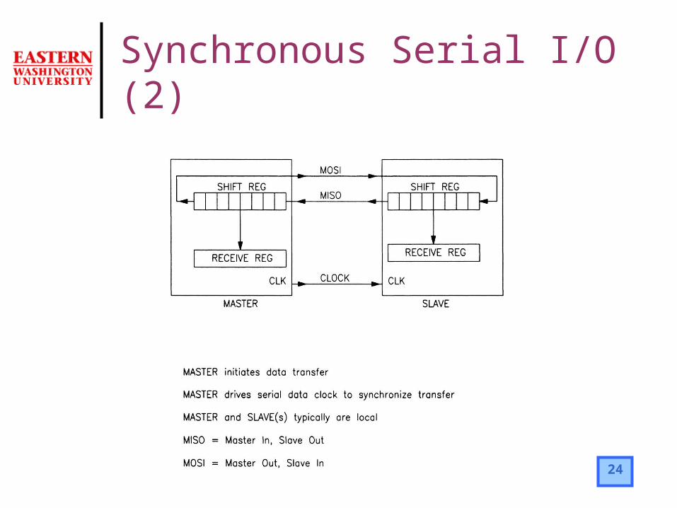
A synchronous serial I/O subsystem is one in which all devices use the same clock.
Synchronous serial systems are typically used when all devices are local, such as on the same circuit board or the same machine.
One device called master controls the data transfer. The other devices are called slaves.
Synchronous Serial I/O (1)
24
Synchronous Serial I/O (2)

25
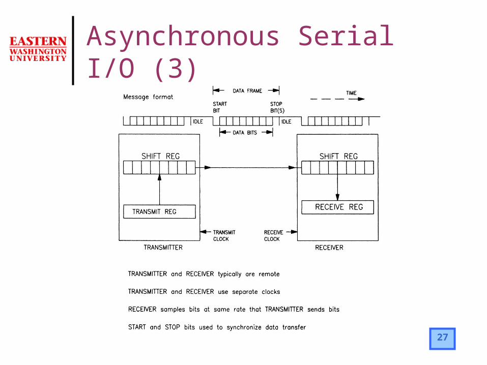
In an asynchronous serial I/O subsystem, each device has its own clock.
Asynchronous serial I/O is typically used when the devices are remote. Although the transmitter and receiver use separate clocks, they must run
at the same rate. The rate of bit transfer is known as the baud rate. For each byte of data sent, the transmitter adds two extra bits:
start bit stop bit
The data together with the start and stop bits is called a frame. By convention, the data line is high when idle. The start bit, being a 0,
brings the data line low, signaling the start of transmission. Eight data bits are then sent, followed by the stop bit. The stop bit is a 1, which leaves the data line high, ready to receive the next byte.
In some cases, a parity bit is transmitted along with the eight data bits. The parity bit is used for error checking of the data byte.
Asynchronous Serial I/O (1)
26
Prior to transmitting any data, the sender and receiver must agree on a specific serial protocol.
A serial protocol needs to specify the following parameters: baud rate number of data bits start and stop bits parity bit
There are many standards for serial protocols. One of the most common is the RS-232 interface.
Typical applications include computer communication to peripherals such as mice, instruments, printers, or other computers
Asynchronous Serial I/O (2)
27
Asynchronous Serial I/O (3)

28
Timer I/O Subsystem (1)
By using a timer the CPU does not have to execute software time-delay loops keep track of time
This also allows to measure time more accurately because interrupts will have no effect
The timer subsystem can generate a stream of pulses at different frequencies and pulse widths. It can also generate single pulses.
The system can act as an internal timer without an output to start and stop a task at set times.
The timer inputs are used to measure period (or frequency) and the pulse width of signals.
Another application is to control the speed of a DC motor using a technique called PWM

29
Timer I/O Subsystem (2)
30
A signal that can be of any value between some maximum and minimum levels is called an analog signal.
Many applications of microcontrollers involve measuring or generating analog signals.
For a microcontroller to use an analog signal, the signal must be converted into digital form.
The 68HC11 has eight built-in A/D, but it does not have a built-in D/A An analog-to-digital converter (A/D) reads an analog voltage or current
and converts it to a binary number to represent its value in volts. Despite the fact that conversions take time, the software that control A/D
converters is usually quite simple
A/D applications: read analog sensors used to measure pressure, temperature, light, battery voltage, etc.
Analog/Digital I/O Subsystem

31
Analog/Digital I/O Subsystem
32
Manipulating I/O mapped registers
I/O interfacing is usually done using bit-manipulation instructions. However these instructions use only direct or indexed addressing. A common example is to use an index register to point to memory mapped registers
Example:…
BIT0 EQU $01 ;bit 0BIT6 EQU $40 ;bit 6REGBAS EQU $1000 ;start address of register blockPORTC EQU $03 ;port C offsetPORTA EQU $04 ;port A offset
LDX #REGBAS ;point to register blockBRCLR PORTC,X BIT0 NO_LEFTBSET PORTB,X BIT6
…