Embed Size (px)
Citation preview
1
Implications for development of effective drilling and completion technologies
Julia F. W. Gale
Stephen E. Laubach
Bureau of Economic Geology, Jackson School of Geosciences,
The University of Texas at Austin, USA
Natural Fracture Study

2
Objective
• Field-verified methodology to identify areas of high productivity in the New Albany Shale
• Focus on thermogenic part of play
• Well experiments
>Natural fractures key for drilling and completion─ Reactivation during hydraulic fracture treatment─ Possible permeability enhancement
>Methods for natural fracture characterization and prediction needed
3
Outline
• Core and outcrop studies SW Indiana• Fracture types and properties• Fracture spatial organization
• Well experiment, W Kentucky• Core and image log data, pilot hole• Prediction of hydraulic fracture treatment
• Input data for modeling of interaction of hydraulic fractures with natural fractures
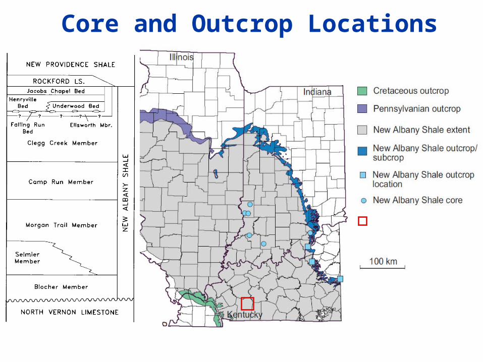
Core and Outcrop Locations
2 southerly outcrops described in Schieber and Lazar (2004 Field Guide)
Kentucky data set and well experiment
After Hasenmueller and Leininger, 1987

Subsurface Fractures
Steeply Dipping, Sealed
Dominant trend NW-SE
Secondary trend E-W
Orientation data from 3 cored wells (Hamilton-Smith et al., 2000)
4 in diameter core
Diversified OperatingMcAtee S26-IV, 2788 ft
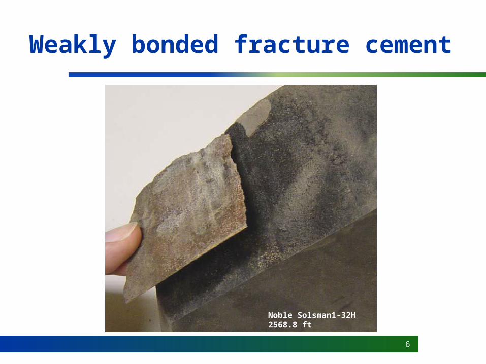
6
Weakly bonded fracture cement
Noble Solsman1-32H2568.8 ft

7
Predicting fracture attributes
IntensitySpatial distribution
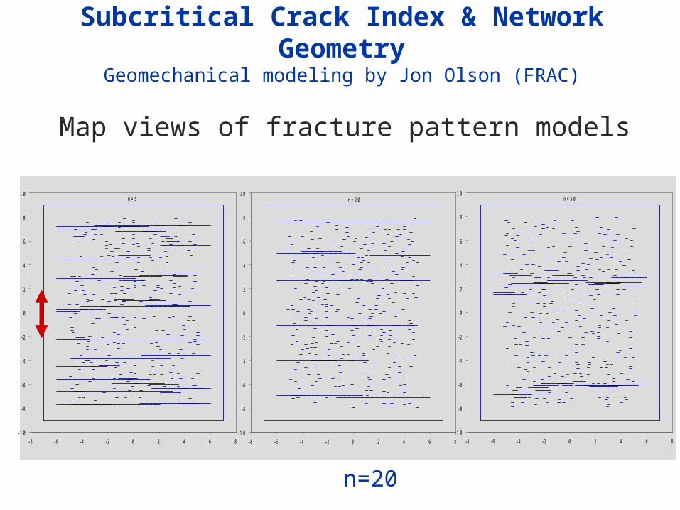
Subcritical Crack Index & Network GeometryGeomechanical modeling by Jon Olson (FRAC)
- 1 0
- 8
- 6
- 4
- 2
0
2
4
6
8
1 0
- 8 - 6 - 4 - 2 0 2 4 6 8
n = 5
- 1 0
- 8
- 6
- 4
- 2
0
2
4
6
8
1 0
- 8 - 6 - 4 - 2 0 2 4 6 8
n = 2 0
- 1 0
- 8
- 6
- 4
- 2
0
2
4
6
8
1 0
- 8 - 6 - 4 - 2 0 2 4 6 8
n = 8 0
n=5 n=20 n=80
Map views of fracture pattern models

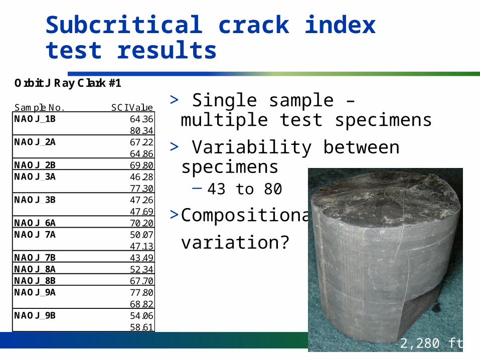
Subcritical Crack Index Testing
Fractures in Noble Solsman 1-32H core
2540
2560
2580
2600
2620
2640
2660
0.01 0.1 1
kinematic aperture, mm
dep
th,
ft
Apparent concentration of fractures
37
66
Mean subcritical indices4 tests for upper unit10 tests for lower unit
High SCI
Mod SCI
Variable subcritical index
10
> Single sample – multiple test specimens
> Variability between specimens─ 43 to 80
>Compositional
variation?
Subcritical crack index test results
Orbit J Ray Clark #1
Sample No. SCI ValueNAOJ_1B 64.36
80.34NAOJ_2A 67.22
64.86NAOJ_2B 69.80NAOJ_3A 46.28
77.30NAOJ_3B 47.26
47.69NAOJ_6A 70.20NAOJ_7A 50.07
47.13NAOJ_7B 43.49NAOJ_8A 52.34NAOJ_8B 67.70NAOJ_9A 77.80
68.82NAOJ_9B 54.06
58.61
2,280 ft
11
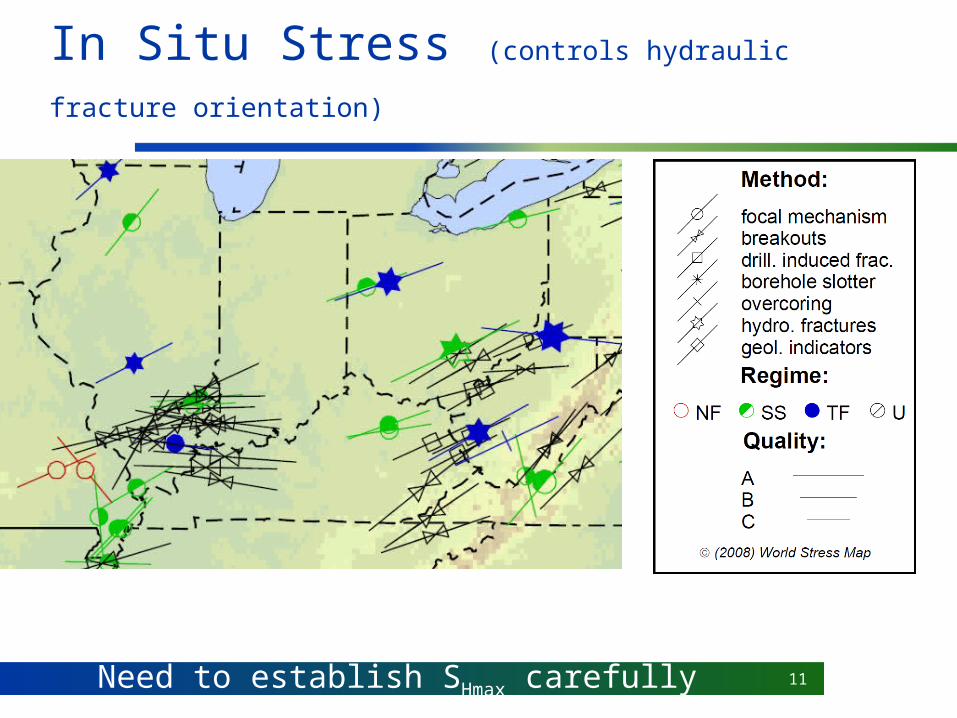
In Situ Stress (controls hydraulic fracture orientation)
Mid-Plate Compression Province, but local variationNeed to establish SHmax carefully
Dom
inant natural
fracture clusters NW
-SE
N
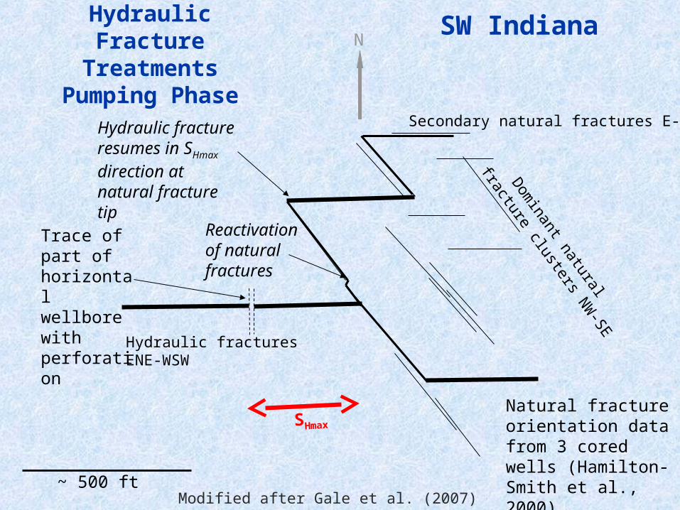
Hydraulic fracture resumes in SHmax direction at natural fracture tip
Trace of part of horizontal wellbore with perforation
Hydraulic Fracture Treatments
Pumping Phase
~ 500 ftModified after Gale et al. (2007)
Hydraulic fractures ENE-WSW
SHmax
Secondary natural fractures E-W
Reactivation of natural fractures
Natural fracture orientation data from 3 cored wells (Hamilton-Smith et al., 2000)
SW Indiana

Well Experiment
McBride and Nelson (1999)Slide: Doug Walser, Pinnacle
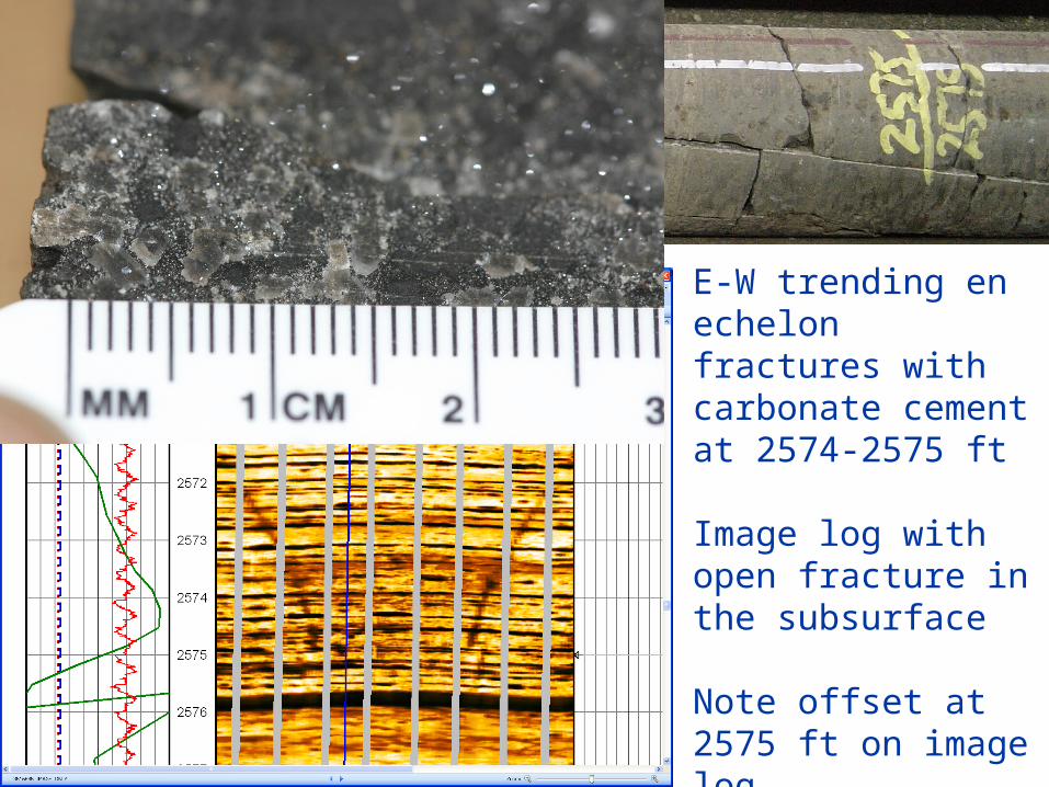
E-W trending en echelon fractures with carbonate cement at 2574-2575 ft
Image log with open fracture in the subsurface
Note offset at 2575 ft on image log.
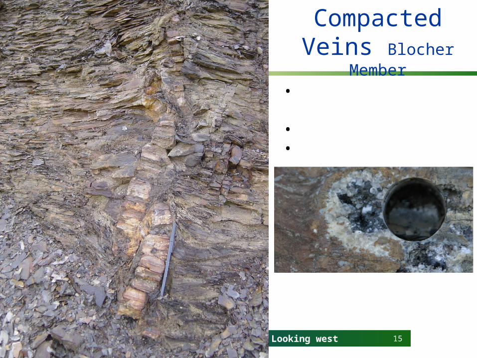
15Looking west
Compacted Veins Blocher Member
• Present in subsurface• Mostly dolomite• Contain porosity

16
In Situ Stress (controls hydraulic fracture orientation)
Mid-Plate Compression Province, but local variationNeed to establish SHmax carefully

NWell ExperimentPrediction
~ 500 ft
Dominant natural fracture cluster E-W
Horizontal wellbore
SHmax
Natural Fractures parallel to SHmax

18
Natural Fracture Input Data for Hydraulic Fracture Modeling
Daugherty Petroleum Inc. (DPI) 2485-21 Christian Co.
>Orientation of SHmax : E - W
>Orientation of opening-mode fractures: E - W dip N or S
>Orientation of faults: Surface faults E - W dip 60° N or S
>Kinematic aperture: 0.05 to 2 mm
>Hydraulic aperture: not known, likely 0 to 2 mm
>Strength of fracture planes: Weak but no test data. Will use data
from Barnett (fractures 1/2 as strong as host shale)
>Height of opening mode fractures 1 m for fractures < 1 mm wide; 10 m for fractures > 1 mm wide
>Spacing of opening mode fractures: 1 to 10 m as base cases

19
Impact of Natural Fractures: Assessment Workflow
> Measure SHmax and natural fracture orientation in subsurface. Core, image logs, dipole sonic logs. Do not rely on surface data.
> Determine composition of host rock and fracture fill
> Measure subcritical crack index
> Determine fracture timing and establish mechanical layering at the time of fracturing

20
Impact of Natural Fractures: Assessment Workflow
> Use geomechanical models and fracture scaling theory to predict intensity and spatial organization
> Verify with microseismic monitoring and core/image logs
> Use to predict likely interaction of hydraulic fractures with natural fractures
> Use production data to verify> Iterate to improve prediction capability
21
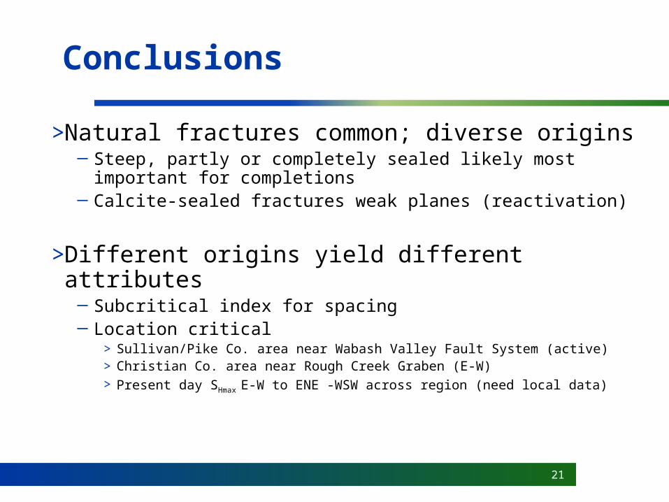
Conclusions
>Natural fractures common; diverse origins─ Steep, partly or completely sealed likely most important
for completions─ Calcite-sealed fractures weak planes (reactivation)
>Different origins yield different attributes─ Subcritical index for spacing─ Location critical
> Sullivan/Pike Co. area near Wabash Valley Fault System (active)> Christian Co. area near Rough Creek Graben (E-W)> Present day SHmax E-W to ENE -WSW across region (need local data)

22
Acknowledgments
>Fracture Research and Application Consortium (FRAC), University of Texas at Austin
>RPSEA – funding for this project
>GTI
>Noble Energy Inc.
>NGas
>ResTech and Pinnacle
>Indiana Geological Survey
>Kentucky Geological Survey
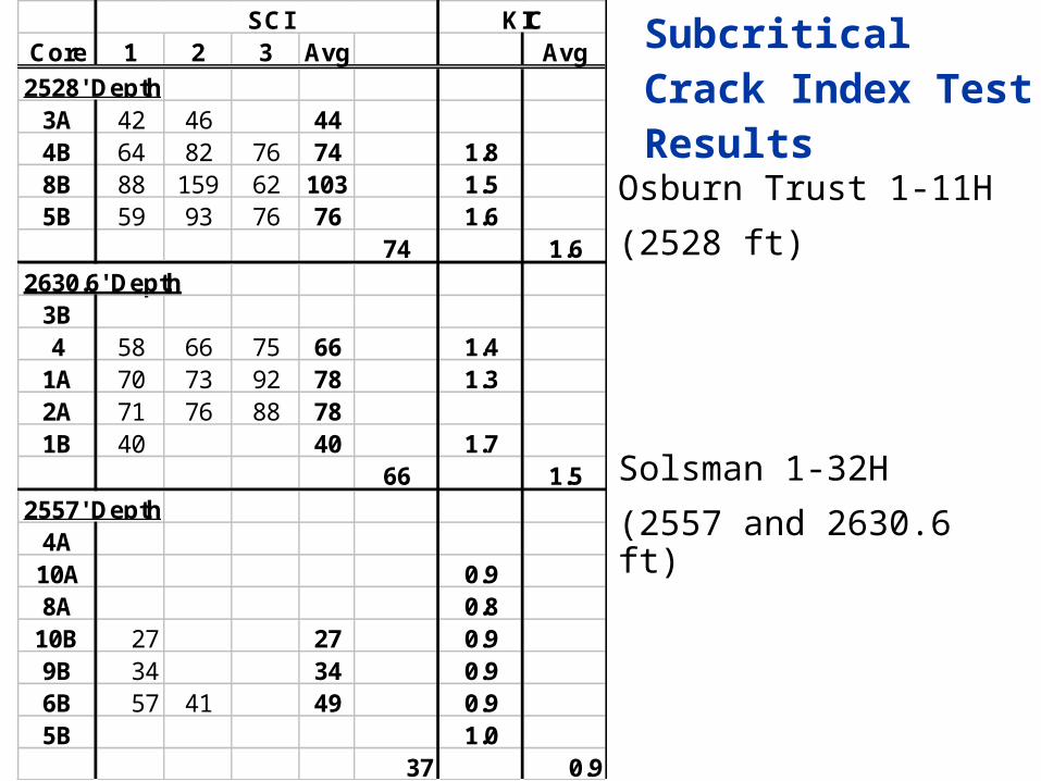
Core 1 2 3 Avg Avg
2528' Depth3A 42 46 444B 64 82 76 74 1.88B 88 159 62 103 1.55B 59 93 76 76 1.6
74 1.62630.6' Depth
3B4 58 66 75 66 1.4
1A 70 73 92 78 1.32A 71 76 88 781B 40 40 1.7
66 1.52557' Depth
4A10A 0.98A 0.8
10B 27 27 0.99B 34 34 0.96B 57 41 49 0.95B 1.0
37 0.9
SCI KIC
Subcritical Crack Index Test Results
Osburn Trust 1-11H
(2528 ft)
Solsman 1-32H
(2557 and 2630.6 ft)
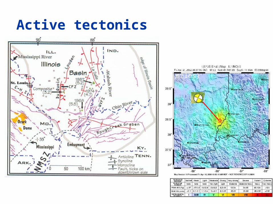
Active tectonics
McBride and Nelson (1999)
Earthquakes Wabash Valley Fault System (normal faults) 18th April 2008 Magnitude 5.2 Strike slip, right lateralDepth 18 km (~ 11 miles)
25
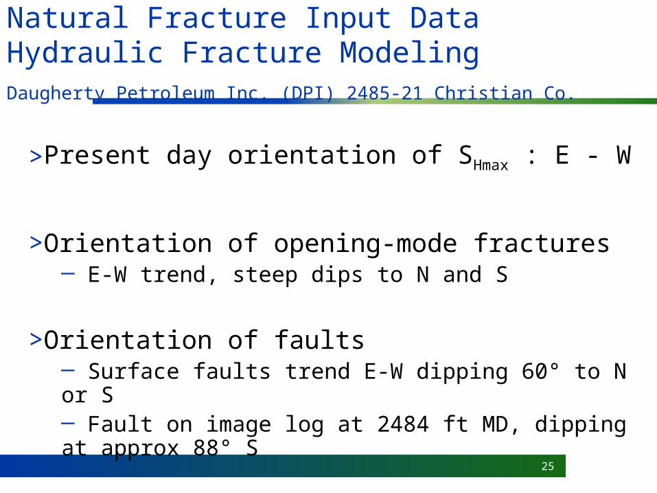
Natural Fracture Input Data Hydraulic Fracture Modeling
Daugherty Petroleum Inc. (DPI) 2485-21 Christian Co.
>Present day orientation of SHmax : E - W
>Orientation of opening-mode fractures─ E-W trend, steep dips to N and S
>Orientation of faults─ Surface faults trend E-W dipping 60° to N or S─ Fault on image log at 2484 ft MD, dipping at approx 88° S

26
Natural Fracture Input Data Hydraulic Fracture Modeling
Daugherty Petroleum Inc. (DPI) 2485-21 Christian Co.
>Natural fracture apertures─ Partly open in image log
>Natural state; popped open by drilling; calcite cement abraded during air drilling
─ Calcite cement in core, breaking within cement ─ Euhedral calcite crystals on fracture surfaces ( 2 mm): pore space of > 2 mm needed to grow─ Narrowest sealed fractures 0.05 mm wide
>Kinematic aperture is of the order of 0.05 to 2 mm
>Hydraulic aperture is not known. Likely 0 to 2 mm.

27
Natural Fracture Input Data Hydraulic Fracture Modeling
Daugherty Petroleum Inc. (DPI) 2485-21 Christian Co.
>Strength of fracture planes─ Weak, but no tensile strength measurements─ Will use data from Barnett tests (fractures half as strong as host shale)
>Height of opening mode fractures─ 1 m for fractures < 1 mm wide ─ 10 m for fractures > 1 mm wide
>Spacing of opening mode fractures─ Will be modeled using subcritical index and mechanical layer thickness─ will use 1 to 10 m as base cases
28
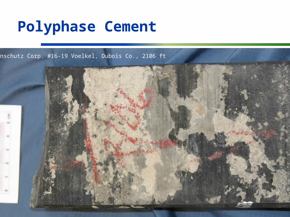
Polyphase Cement
Anschutz Corp. #16-19 Voelkel, Dubois Co., 2106 ft
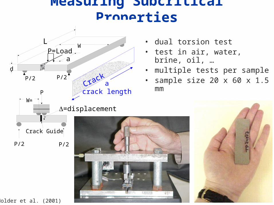
Measuring Subcritical Properties
• dual torsion test• test in air, water, brine, oil, …• multiple tests per sample• sample size 20 x 60 x 1.5 mmd
P/2
P=Load
P/2 P/2
PWm
P/2
Crack Guide
=displacement
LW
a
acrack length
Crack
Holder et al. (2001)
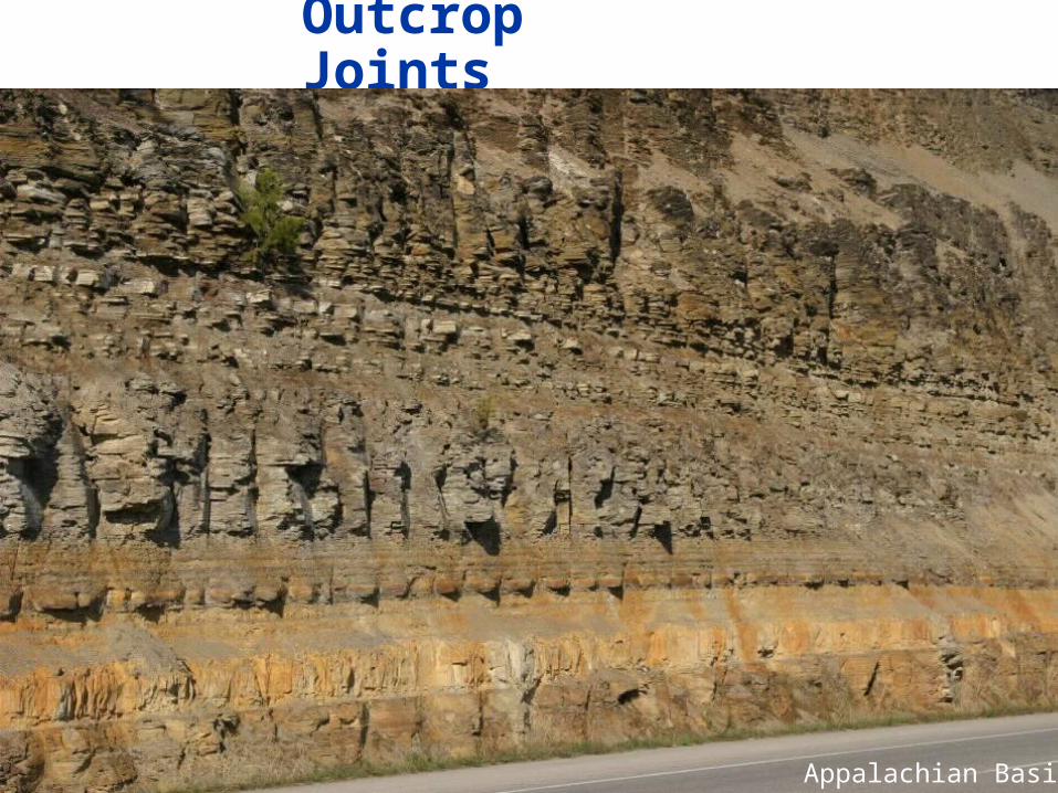
Outcrop Joints
Appalachian Basin