Embed Size (px)
Citation preview

1
IE 243MANUFACTURING PROCESSES
Material Removal Processes
2
Definition of Material Removal Processes
• Material removal processes are shaping operations. The common feature is removal of material from a starting workpart so the remaining part has the desired shape.
• Variety of work materials can be machined. Most frequently applied to metals.
• Variety of part shapes and special geometry features possible, such as: Screw threads, accurate round holes, very straight edges and surfaces.
• Good dimensional accuracy and surface finish is possible.
• However material removal processes are time consuming and wasteful of material.

3
Definition of Material Removal Processes
• There are three categories:
– Machining – Abrasive operations– Nontraditional operations

4
Material Removal ProcessesClassification
• Machining: – Material removed from the surface of the workpart by
means of sharp cutting tools.• Examples are turning, milling, drilling, etc.
turning milling
drilling
5
Material Removal ProcessesClassification
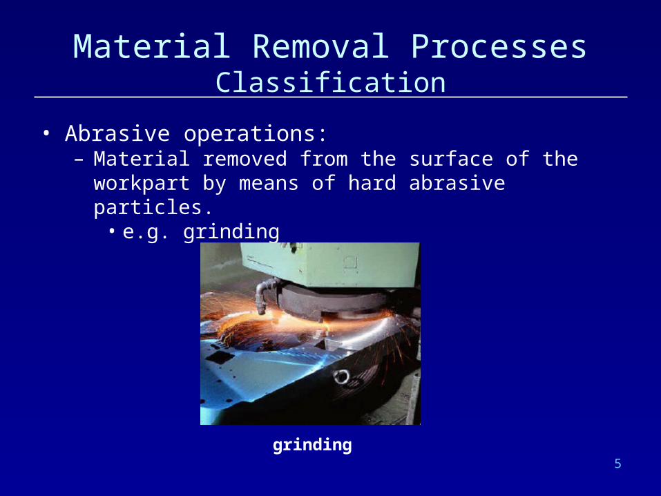
• Abrasive operations: – Material removed from the surface of the workpart by
means of hard abrasive particles.• e.g. grinding
grinding

6
Material Removal ProcessesClassification
• Nontraditional operations: – Various energy forms other than sharp cutting tool to
remove material• e.g. electro-discharge machining, water jet cutting etc.
Electro-discharge machining

7
Material Removal ProcessesMachining
• Relative motion between the cutting tool and the workpiece develops a cutting action.
• Cutting action involves shear deformation of work material to form a chip.
• As chip is removed, a new surface is exposed.

8
Material Removal ProcessesMachining
• Chip formation due to shear

9
Material Removal ProcessesMachining
• Some terms and definitions in machining– There is relative motion between the workpiece and
the cutting tool.• Primary motion: Cutting motion (defined by cutting
speed)• Secondary motion: Feed motion (defined by the feed
rate)• Depth of cut (defines the amount of plunging of the tool
into the workpiece)
Any machining operation involves these quantities.

10
Material Removal ProcessesMachining
• Most important machining operations are– Turning– Milling– Drilling
• Other machining operations are– Shaping and planing– Broaching– Sawing
11
Material Removal ProcessesMachining
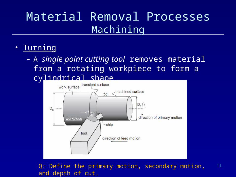
• Turning– A single point cutting tool removes material from a
rotating workpiece to form a cylindrical shape.
Q: Define the primary motion, secondary motion, and depth of cut.

12
Material Removal ProcessesMachining
• Drilling– Used to create a round hole, usually by means of a
rotating tool (drill bit) that has two cutting edges.
Q: Define the primary motion, secondary motion, and depth of cut.

13
Material Removal ProcessesMachining
• Milling– Rotating multiple-cutting-edge tool is moved slowly
relative to work to generate plane or straight surface.– There are two forms of milling;
• Peripheral milling
• Face milling
Q: Define the primary motion, secondary motion, and depth of cut.

14
Material Removal ProcessesMachining
• Classification of the cutting tools– Single-Point Tools:
• One cutting edge
• Turning uses single point tools
• Point is usually rounded to form a nose radius
– Multiple Cutting Edge Tools:
• More than one cutting edge
• Motion relative to work usually achieved by rotating
• Drilling and milling use rotating multiple cutting edge tools.

15
Material Removal ProcessesMachining
• Classification of the cutting tools– Single-Point Tools:
• One cutting edge • Turning uses single point tools • Point is usually rounded to form a nose radius
– Multiple Cutting Edge Tools: • More than one cutting edge • Motion relative to work usually achieved by rotating
• Drilling and milling use rotating multiple cutting edge tools.

16
Material Removal ProcessesMachining
• Analysis – We know that shear is involved for formation of the chips.– In order to analyze the physics orthogonal cutting model
will be used. – Orthogonal cutting model is a simplified 2D model of the
machining operations. Oblique cutting
(more realistic)
Orthogonal cutting

17
Material Removal ProcessesMachining
• Analysis – Basic terms:
• Chip thickness ratio:
0
c
trt
Chip thickness ratio is always greater than 1.
Rake angle may be positive or negative!
18
Material Removal ProcessesMachining
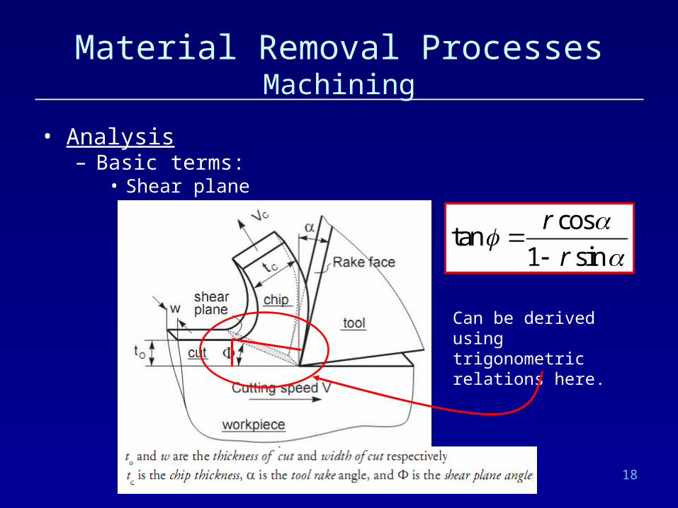
• Analysis – Basic terms:
• Shear plane angle:
Can be derived using trigonometric relations here.
costan
1 sin
r
r

19
Material Removal ProcessesMachining
• Analysis – Forces in cutting:
• Forces acting on the chip:
: Friction force on tool chip interface
(friction coefficient is )
: Normal force to friction
: Shear force
: Normal force to shear
: Resultant of the forces and
: Resultant of the forces
s
n
s
F
N
F
F
R F N
R F
and nF
These forces cannot be measured directly!
Note that F N
20
Material Removal ProcessesMachining
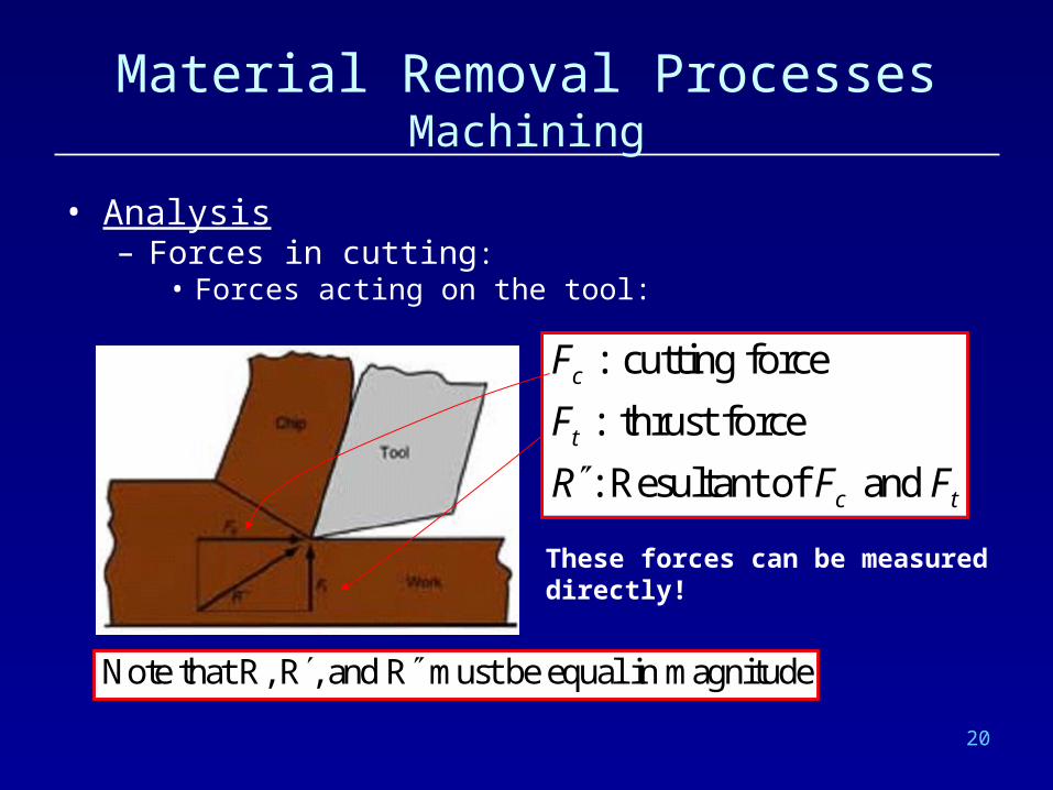
• Analysis – Forces in cutting:
• Forces acting on the tool:
: cutting force
: thrust force
: Resultant of and
c
t
c t
F
F
R F F
These forces can be measured directly!
Note that R, R , and R must be equal in magnitude

21
Material Removal ProcessesMachining
• Analysis – Forces in cutting:
• Force circle:The circle whose diameter is the resultant R, and thrust and cutting forces are the vertical and horizontal components of the resultant R.
Cutting tool

22
Material Removal ProcessesMachining
• Analysis – Forces in cutting:
• Using this force circle one can derive:
sin cos
cos sin
cos sin
sin cos
c t
c t
s c t
n c t
F F F
N F F
F F F
F F F
Cutting tool
Φ
α

23
Material Removal ProcessesMachining
• Analysis – Power and Energy Relations:
• Power required to perform a machining operation
where Fc is the cutting force, v is the cutting speed.
• Power is traditionally expressed in kW or HP (horsepower)– 1 HP = 0.746 kW
c cP F v

24
Material Removal ProcessesMachining
• Analysis – Power and Energy Relations:
• The efficiency of the machine tool (the machine used for the machining operation) may not be 100 %, thus not all of the the power it takes is utilized for the machining. Therefore the gross power required is:
where e is the efficiency of the machine tool.
cg
PP
e
25
Material Removal ProcessesMachining
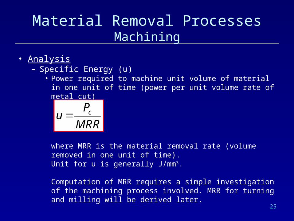
• Analysis – Specific Energy (u)
• Power required to machine unit volume of material in one unit of time (power per unit volume rate of metal cut)
where MRR is the material removal rate (volume removed in one unit of time).Unit for u is generally J/mm3.
Computation of MRR requires a simple investigation of the machining process involved. MRR for turning and milling will be derived later.
cPuMRR

26
Material Removal ProcessesMachining
• Analysis – General Conclusions:
• Increasing the rake angle increases the shear plane angle.
• Increase in shear plane angle means smaller shear plane and thus smaller shear force.
High shear angle Small shear angle
27
Material Removal ProcessesMachining
• Analysis – General Conclusions:
• However increasing the rake angle decreases the tool strength. If strong tool are required, negative rake angles may be preferred.
• Specific energy for a work material under specific cutting conditions is defined. That is if MRR is known, power requirement can be inferred directly.
• Approximately 98% of the energy in machining is converted into heat. This can cause temperatures to be very high at the tool-chip interface.

28
References
K. Tur, Manufacturing Processes Lecture Notes, 2004
E. Kılıç, Manufacturing Technologies, Lecture Notes, 2005
E. Kılıç, Manufacturing Engineering, Lecture Notes, 2005
and
http://www.diamond-mold.com/edm.php