Embed Size (px)
Citation preview
2
Grading criteria for electric strikes andlocksets include:
• Cycle testing - electric strike is cycled with compatible hardware at a rate not to exceed 30 cycles per minute(See figure1.3)
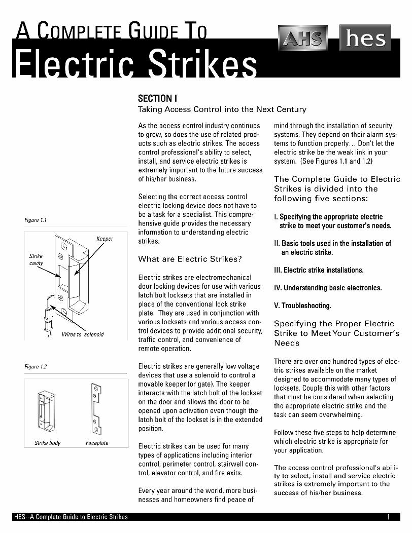
• Static strength testing - with the electric strike in the locked position,continuous force is applied to a specified point on a door at a rate not slower than 10 pounds-force (44N) nor faster than 20 pounds-force (90 N) per second until the rated static strength is reached and held for 1 minute prior to separation (See figure 1.4)
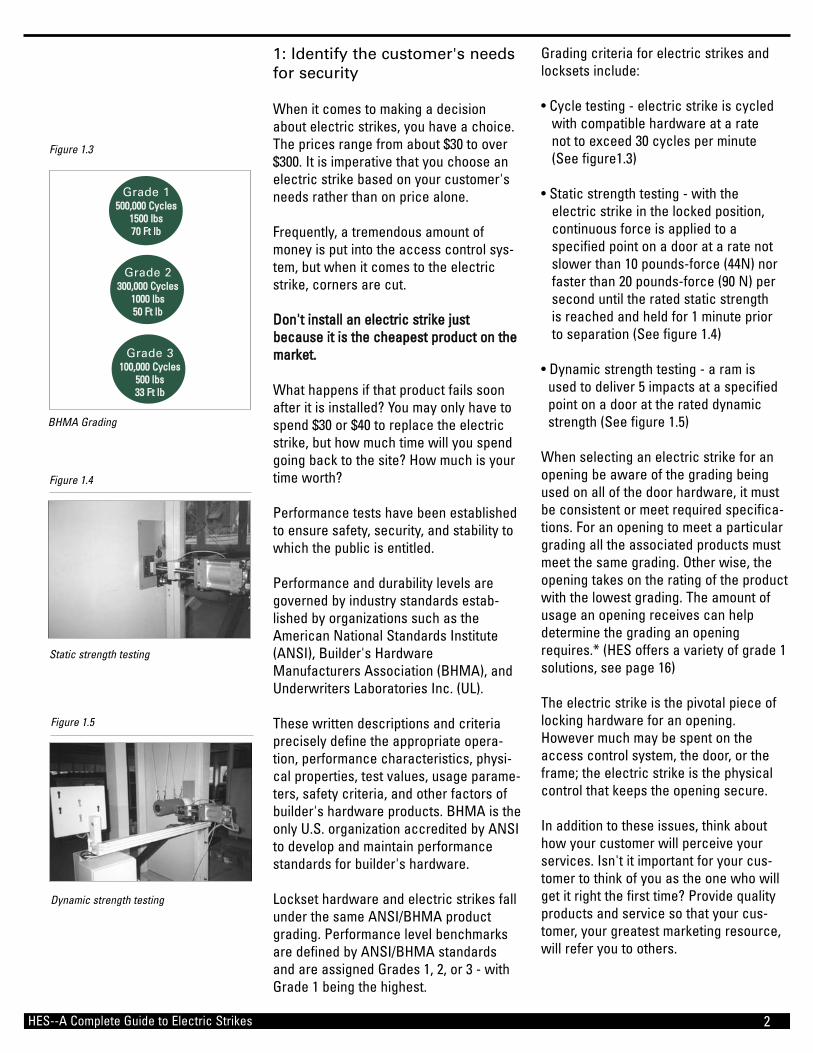
• Dynamic strength testing - a ram is used to deliver 5 impacts at a specified point on a door at the rated dynamic strength (See figure 1.5)
When selecting an electric strike for anopening be aware of the grading beingused on all of the door hardware, it mustbe consistent or meet required specifica-tions. For an opening to meet a particulargrading all the associated products mustmeet the same grading. Other wise, theopening takes on the rating of the productwith the lowest grading. The amount ofusage an opening receives can helpdetermine the grading an openingrequires.* (HES offers a variety of grade 1solutions, see page 16)
The electric strike is the pivotal piece oflocking hardware for an opening.However much may be spent on theaccess control system, the door, or theframe; the electric strike is the physicalcontrol that keeps the opening secure.
In addition to these issues, think abouthow your customer will perceive yourservices. Isn't it important for your cus-tomer to think of you as the one who willget it right the first time? Provide qualityproducts and service so that your cus-tomer, your greatest marketing resource,will refer you to others.
1: Identify the customer's needs for security
When it comes to making a decisionabout electric strikes, you have a choice.The prices range from about $30 to over$300. It is imperative that you choose anelectric strike based on your customer'sneeds rather than on price alone.
Frequently, a tremendous amount ofmoney is put into the access control sys-tem, but when it comes to the electricstrike, corners are cut.
DDoonn''tt iinnssttaallll aann eelleeccttrriicc ssttrriikkee jjuussttbbeeccaauussee iitt iiss tthhee cchheeaappeesstt pprroodduucctt oonn tthheemmaarrkkeett..
What happens if that product fails soonafter it is installed? You may only have tospend $30 or $40 to replace the electricstrike, but how much time will you spendgoing back to the site? How much is yourtime worth?
Performance tests have been establishedto ensure safety, security, and stability towhich the public is entitled.
Performance and durability levels aregoverned by industry standards estab-lished by organizations such as theAmerican National Standards Institute(ANSI), Builder's HardwareManufacturers Association (BHMA), andUnderwriters Laboratories Inc. (UL).
These written descriptions and criteriaprecisely define the appropriate opera-tion, performance characteristics, physi-cal properties, test values, usage parame-ters, safety criteria, and other factors ofbuilder's hardware products. BHMA is theonly U.S. organization accredited by ANSIto develop and maintain performancestandards for builder's hardware.
Lockset hardware and electric strikes fallunder the same ANSI/BHMA productgrading. Performance level benchmarksare defined by ANSI/BHMA standardsand are assigned Grades 1, 2, or 3 - withGrade 1 being the highest.
HES--A Complete Guide to Electric Strikes
Static strength testing
Figure 1.4
BHMA Grading
Figure 1.3
Dynamic strength testing
Figure 1.5
Grade 1550000,,000000 CCyycclleess
11550000 llbbss 7700 FFtt llbb
Grade 3110000,,000000 CCyycclleess
550000 llbbss3333 FFtt llbb
Grade 2330000,,000000 CCyycclleess
11000000 llbbss5500 FFtt llbb
3
When you are dealing with existing doorhardware, you should choose an electricstrike that will perform the same functionas the strike plate supplied with the lock.(After all an electric strike without elec-tricity is nothing more than an expensivestrike plate). To properly match the two,you only need to know five basic principles.
11)) UUnnddeerrssttaanndd tthhee ttyyppee ooff bboolltt oorr bboollttss oonntthhee lloocckk..
There are as many as three componentsto some locksets, the latch bolt, deadlatchand deadbolt. Remember, the electricstrike will need to provide the same func-tion as the strike plate provided with thelockset. Therefore, a basic understandingof the lock is an important requirementwhen choosing an electric strike.
• A llaattcchh bboolltt is a spring loaded bolt that is ramped on the closing side to enable it to be depressed upon the closing of the door. The bolt then will spring outward when positioned over the strike cavity to secure the door.
• A ddeeaaddbboolltt is a bolt that must be manually extended into the strike cavity to secure and lock a door. The deadbolt must similarly be manually retracted from the strike cavity to unlock a door.
• A ddeeaaddllaattcchh is designed to work in conjunction with the latch bolt. When the deadlatch is depressed, it locks the latch bolt in the extended position. If the deadlatch is not depressed, the latch bolt can be retracted with a credit card.
ANSI specifications dictate the dimen-sions for the body of a mortise lock andits components, but they don't state howthe latch bolt, deadlatch and deadbolt areto be arranged on the lock. Therefore,most of the manufacturers design theirmortise locks in slightly different configu-rations. This makes it important to knowwhich lockset manufacturer you are usingwhen choosing an electric strike toaccommodate these locks.
2: Determine the type of locksetthat the electric strike will inter-act with: Cylindrical, Mortise, orExit Device?
An understanding of the basic relation-ship between the lockset and electricstrike is the next essential step in deter-mining what type of electric strike to use.
There are three main types of locksets:cylindrical, mortise, and exit devices.Knowing what type of lockset is beingused is important when selecting an elec-tric strike.
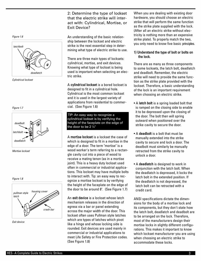
A ccyylliinnddrriiccaall lloocckksseett is a bored lockset isdesigned to fit in a cylindrical hole.Cylindrical is the most common locksetand it is used in the largest variety ofapplications from residential to commer-cial. (See Figure 1.6)
A mmoorrttiissee lloocckksseett is a lockset the case ofwhich is designed to fit in a mortise in theedge of a door. The term "mortise" is awood worker's term referring to a rectan-gle cavity cut into a piece of wood toreceive a mating tenon (as in a mortisejoint). This is a heavy duty lockset usedoften in commercial or industrial applica-tions. This lockset may have multiple boltsto interact with. Tip: an easy way to rec-ognize a mortise lockset is by verifyingthe height of the faceplate on the edge ofthe door to be around 8". (See Figure 1.7)
An eexxiitt ddeevviiccee is a lockset whose latchmechanism releases in the direction ofegress via a bar or panel extendingacross the major width of the door. Thislockset often uses Pullman style latcheswhich are types of latches which pivotlike a hinge and whose locking side isrounded. Exit devices are used mainly incommercial or industrial applications tomeet Life Safety or Fire Protection codes.(See Figure 1.8)
HES--A Complete Guide to Electric Strikes
Cylindrical lockset
Figure 1.6
Mortise lockset
Figure 1.7
Exit device
Figure 1.8
crash bar
housing coverpullman stylelatch
latchbolt
deadbolt
deadlatch
deadlatch
TIP: An easy way to recognize a cylindrical lockset is by verifying theheight of the faceplate on the edge ofthe door to be 2 ¼"
latchbolt

4
below the center line of the electricstrike. Some electric strikes require theproper handing to line up properly, butmany now are non-handed.
Figures 1.10 and 1.11 show the differencein the placement of a cylindrical lock vs. amortise lock with an electric strike.
55)) AAlliiggnn tthhee eelleeccttrriicc ssttrriikkee ttoo pprrooppeerrllyy ddeepprreessss tthhee ddeeaaddllaattcchh..
Many locksets also have deadlatches. Adeadlatch is a latch in which the latchbolt is positively held in the projectedposition by an auxiliary mechanism. Thislatch functions as an "anti-pick" device toprevent tampering. Accommodating alockset with a latch bolt and a deadlatch,the electric strike must be designed toproperly depress the deadlatch. Failure todo so will compromise the security of thelockset.
3: Determine the type of framethe electric strike will beinstalled into: Hollow-metal,Aluminum, or Wood
There are basically three types of framesthat will be encountered in the field - hol-low metal (steel), aluminum, and wood.
HHoollllooww mmeettaall ffrraammeess are the most com-mon type of frame. If the electric strike isbeing installed into a hollow-metal frame,almost any electric strike will work.However, there is an old adage about"hollow-metal" frames and that is: "hollow-metal rarely is." What this means is, "hol-low-metal" door frames are usually nothollow - they are often filled with con-crete or other materials. This is requiredto stabilize the door frame.
Have you ever tried to install an electricstrike with a solenoid protruding from it?It is not difficult to do if the door frame istruly "hollow." It becomes very difficult ifthe frame is not "hollow." Many electricstrikes today have an internal solenoidmaking them easy to install. In manyapplications, building codes prevent theinstallation of an electric strike designed
HES--A Complete Guide to Electric Strikes
Door jamb description
Figure 1.9
ELECTRICSTRIKEC L
LOCK
C L
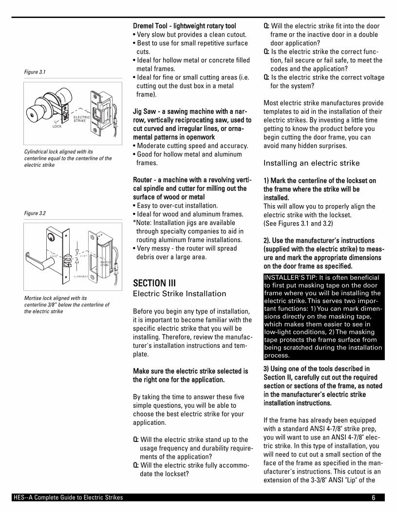
Cylindrical lock aligned with its centerline equal to the centerline of theelectric strike
Figure 1.10
LOCK
ELECTRICSTRIKE
3/8"C L
C L
3/8" OFFSET
Mortise lock aligned with its centerline 3/8” below the centerline ofthe electric strike
Figure 1.11
Door rabbet
Strike lip
Door stop
FaceANSI Dust box
22)) WWhheetthheerr ttoo uussee aa mmoorrttiisseedd eelleeccttrriicc ssttrriikkee oorr aa ssuurrffaaccee mmoouunntteedd eelleeccttrriicc ssttrriikkee sshhoouulldd bbee bbaasseedd oonn tthhee ttyyppee ooff hhaarrddwwaarree oonn tthhee ddoooorr..
The term "mortise lock" stems from therectangle shape of the lock body and therectangle cavity required in the edge ofthe door for installation.
Similarly, when an electric strike isinstalled in a door frame so that the faceplate is "flush" with the rabbet of theframe, it is referred to as a mortise instal-lation. Mortise electric strikes are used toaccommodate most types of locksets,including mortise locks, cylindrical locks,cylindrical deadbolts and unit locks.
A "surface mounted" electric strike ismounted on the surface or soffit of thedoor frame. These electric strikes areused to accommodate "rim" (or surface)mounted exit devices and surface mount-ed latch bolts and deadbolts. Oftentimesthese electric strikes are not completelysurface mounted. The faceplate will besurface mounted, but the body of theelectric strike will still need to be mor-tised into the frame. (See Figure 1.9)
33)) TThhee eelleeccttrriicc ssttrriikkee mmuusstt hhaavvee ccoorrrreecctt ccaavviittyy ddeepptthh ttoo aaccccoommmmooddaattee tthhee lloocckk..
Latch bolts have various lengths (or pro-jections) so it is important to choose anelectric strike with the correct cavitydepth to accommodate the latch bolt. Anyelectric strike selected should have thecavity positioned to match up with thebolt of the lockset.
44)) TThhee cceenntteerr lliinneess ooff tthhee lloocckk aanndd eelleeccttrriicc ssttrriikkee sshhoouulldd lliinnee uupp pprrooppeerrllyy bbaasseedd oonn tthhee ttyyppee ooff lloocckk..
It is important to evaluate whether or notthe type of lockset used is on center withthe electric strike cavity. For example, thecenter line of a cylindrical lock shouldmatch up with the center line of the elec-tric strike cavity, whereas the center lineof the mortise lock is positioned 3/8"

5
Fail safe is when the power fails, theunlocked opening is safe to enter andexit, the electric strike requires power tolock.
Different applications will require eitherfail secure or fail safe electric strikes. Ifthe door is "fire fated," a fail secure elec-tric strike is necessary. This type of dooris a barrier door. If the door is classifiedas a "life safety" door, the operation of theelectric strike must be fail safe to allowfree egress.
If ADA (Americans with Disabilities Act)laws apply to the door, an audible (buzzer)or visual (LED) indication of the door sta-tus may also be necessary. AAllwwaayyss vveerriiffyyllooccaall ccooddeess aanndd rreegguullaattiioonnss tthhaatt mmuusstt bbeemmeett wwhheenn sseelleeccttiinngg aann eelleeccttrriicc ssttrriikkee..
SSEECCTTIIOONN IIIIBasic Tools Used in ElectricStrike Installation
Various tools are used in the installationof an electric strike. Your choice of toolswill depend on your personal preferenceand the type of installation you are doing.
The following is a list of the most com-monly used tools and some points ofinterest about them. All of these toolsrequire varying degrees of skill or prac-tice and can be used with a variety of toolbits depending on the application and kindof cut. Always wear a protective shield orglasses when using these tools.
RReecciipprrooccaattiinngg SSaaww ((SSaawwzzaallll)) -- aa ppoorrttaabblleeppoowweerr ssaaww wwiitthh aa rreecciipprrooccaattiinngg bbllaaddee,, (ablade that moves alternately backwardand forward)• Moderate cutting speed and accuracy.• Good for hollow metal and aluminum
frame.
DDiiee GGrriinnddeerr -- hheeaavvyy dduuttyy rroottaarryy ttooooll• Ideal for hollow metal and concrete
filled metal frames.• Easy to over-cut installation.• Leaves a slight burn mark around the
cutout (approximately 1/16" to 1/8").
with an external solenoid, when theinstallation penetrates the drywall.AAlluummiinnuumm ffrraammeess usually encase glass,both in the door itself and in the adjoiningwalls. Many times the glass is encasedwithin 1-1/4" of the surface of the frame,making the overall depth of the electricstrike important. Selecting an electricstrike that is compact enough to beinstalled in these frames without cuttinginto the glass can save you money andtime in the field.
WWoooodd ffrraammee installations present many ofthe same concerns as you might find withconcrete filled metal frames. Using anelectric strike that is compact or has aninternal solenoid can help with the easeof installation.
4: Assess the voltage requirements
Electric strikes come in a variety of volt-ages with 12 and 24 being the most com-mon. If no system is present, you canchoose the voltage and design your sys-tem around it.
Many people choose 12 volts because ofthe easy access to batteries to back-upthe system. A good reason to choose 24volts is due to a lower current draw toallow multiple strikes with one powersource. (See Section IV, UnderstandingBasic Electronics.)
5: Identify the codes andrequirements for the place ofinstallation
Local building codes and requirementsare always an important considerationwhen specifying an electric strike.
Codes regarding Life Safety or FireProtection will dictate how the electricstrike must function, such as fail secureor fail safe.
Fail secure means when the power failsthe opening remains secure. In otherwords, the electric strike requires powerto unlock.
HES--A Complete Guide to Electric Strikes
Internal vs. external solenoid
Figure 1.12
internal solenoid
external solenoid
6
QQ:: Will the electric strike fit into the door frame or the inactive door in a double door application?
QQ:: Is the electric strike the correct func-tion, fail secure or fail safe, to meet the codes and the application?
QQ:: Is the electric strike the correct voltage for the system?
Most electric strike manufactures providetemplates to aid in the installation of theirelectric strikes. By investing a little timegetting to know the product before youbegin cutting the door frame, you canavoid many hidden surprises.
Installing an electric strike
11)) MMaarrkk tthhee cceenntteerrlliinnee ooff tthhee lloocckksseett oonntthhee ffrraammee wwhheerree tthhee ssttrriikkee wwiillll bbeeiinnssttaalllleedd..This will allow you to properly align theelectric strike with the lockset. (See Figures 3.1 and 3.2)
22)).. UUssee tthhee mmaannuuffaaccttuurreerr''ss iinnssttrruuccttiioonnss((ssuupppplliieedd wwiitthh tthhee eelleeccttrriicc ssttrriikkee)) ttoo mmeeaass--uurree aanndd mmaarrkk tthhee aapppprroopprriiaattee ddiimmeennssiioonnssoonn tthhee ddoooorr ffrraammee aass ssppeecciiffiieedd..
33)) UUssiinngg oonnee ooff tthhee ttoooollss ddeessccrriibbeedd iinnSSeeccttiioonn IIII,, ccaarreeffuullllyy ccuutt oouutt tthhee rreeqquuiirreeddsseeccttiioonn oorr sseeccttiioonnss ooff tthhee ffrraammee,, aass nnootteeddiinn tthhee mmaannuuffaaccttuurreerr''ss eelleeccttrriicc ssttrriikkeeiinnssttaallllaattiioonn iinnssttrruuccttiioonnss..
If the frame has already been equippedwith a standard ANSI 4-7/8" strike prep,you will want to use an ANSI 4-7/8" elec-tric strike. In this type of installation, youwill need to cut out a small section of theface of the frame as specified in the man-ufacturer's instructions. This cutout is anextension of the 3-3/8" ANSI "Lip" of the
DDrreemmeell TTooooll -- lliigghhttwweeiigghhtt rroottaarryy ttooooll• Very slow but provides a clean cutout.• Best to use for small repetitive surface
cuts.• Ideal for hollow metal or concrete filled
metal frames.• Ideal for fine or small cutting areas (i.e.
cutting out the dust box in a metal frame).
JJiigg SSaaww -- aa ssaawwiinngg mmaacchhiinnee wwiitthh aa nnaarr--rrooww,, vveerrttiiccaallllyy rreecciipprrooccaattiinngg ssaaww,, uusseedd ttooccuutt ccuurrvveedd aanndd iirrrreegguullaarr lliinneess,, oorr oorrnnaa--mmeennttaall ppaatttteerrnnss iinn ooppeennwwoorrkk• Moderate cutting speed and accuracy.• Good for hollow metal and aluminum
frames.
RRoouutteerr -- aa mmaacchhiinnee wwiitthh aa rreevvoollvviinngg vveerrttii--ccaall ssppiinnddllee aanndd ccuutttteerr ffoorr mmiilllliinngg oouutt tthheessuurrffaaccee ooff wwoooodd oorr mmeettaall• Easy to over-cut installation.• Ideal for wood and aluminum frames. *Note: Installation jigs are available
through specialty companies to aid in routing aluminum frame installations.
• Very messy - the router will spread debris over a large area.
SSEECCTTIIOONN IIIIIIElectric Strike Installation
Before you begin any type of installation,it is important to become familiar with thespecific electric strike that you will beinstalling. Therefore, review the manufac-turer's installation instructions and tem-plate.
MMaakkee ssuurree tthhee eelleeccttrriicc ssttrriikkee sseelleecctteedd iisstthhee rriigghhtt oonnee ffoorr tthhee aapppplliiccaattiioonn..
By taking the time to answer these fivesimple questions, you will be able tochoose the best electric strike for yourapplication.
QQ:: Will the electric strike stand up to the usage frequency and durability require- ments of the application?
QQ:: Will the electric strike fully accommo- date the lockset?
HES--A Complete Guide to Electric Strikes
ELECTRICSTRIKEC L
LOCK
C L
Cylindrical lock aligned with its centerline equal to the centerline of theelectric strike
Figure 3.1
LOCK
ELECTRICSTRIKE
3/8"C L
C L
3/8" OFFSET
Mortise lock aligned with its centerline 3/8” below the centerline ofthe electric strike
Figure 3.2
INSTALLER'S TIP: It is often beneficialto first put masking tape on the doorframe where you will be installing theelectric strike. This serves two impor-tant functions: 1) You can mark dimen-sions directly on the masking tape,which makes them easier to see inlow-light conditions, 2) The maskingtape protects the frame surface frombeing scratched during the installationprocess.

7
The electric strike chosen for a woodframe installation will only be as strong asits ability to be secured to the wood.Therefore, you may want to select anelectric strike with a longer face plate.This will allow you to place the mountingscrews further away from the electricstrike cutout, where they can be bettersecured into the wood. (See Figure 3.5)
Aluminum frames are made in many dif-ferent styles. The electric strike may bepositioned close to the edge (the face) ofthe frame, similar to that of a metal frameinstallation. Or, the electric strike may bepositioned a distance away from the edgeof the frame, similar to that of a woodframe. These installations will also requirethat an extended lip be added to the frontof the electric strike to accommodate thelonger reveal. (See Figure 3.6)
IInnssttaalllliinngg aa ssuurrffaaccee mmoouunntteedd eelleeccttrriiccssttrriikkee ttoo aaccccoommmmooddaattee aa ssuurrffaaccee mmoouunntteeddeexxiitt ddeevviiccee
When trying to accommodate a surfacemounted exit device, the electric strikemust replace the existing strike plate toperform the same function. Be aware ofthe clearance between the housing coverof the exit device and the frame; thesedimensions may vary between 7/8" (steelframe) and 5/8" (aluminum frame) depend-
frame, onto the frame face, which will becut from 5/8" to 2-1/2", depending on theelectric strike selected. (See Figure 3.3)
In most metal frame applications, a sec-tion of the ANSI dust box will also need tobe removed to allow enough room (depth)for the electric strike to be installed. It is important to remove only the bottom sec-tion of the dust box, so that the weldedmounting tab sections remain in place. Ifthe metal frame was not equipped with anANSI frame preparation or if the ANSIdust box is completely removed, then youwill need to install mounting tabs in theframe for the electric strike.If the frame is hollow, then the electricstrike should be easy to insert into theframe preparation. However, if the frameis wood or has been filled with concreteor other materials, you will need to createa cavity large enough to install the elec-tric strike. This can be accomplished witha hammer and chisel by simply chippingaway the material. In more difficult casesyou may find hardened concrete filling theframe. This type of installation mayrequire the use of a "hammer drill" orother devices to remove the requiredmaterial.
In both of these situations it is easy tounderstand why you should select anelectric strike with an internally mountedsolenoid. An electric strike with a protrud-ing solenoid would be very difficult toinstall in these frames.
An important difference between a metalframe and a wood frame is the reveal ofthe frame. This refers to the distance theelectric strike is set back into the frameaway from the frame face. Many woodframe installations require the addition ofan extended lip to the front of the electricstrike to accommodate the longer reveal.Additionally, many wood frames have adecorative wood trim, which extends theactual reveal even further.
HES--A Complete Guide to Electric Strikes
3/4[19.05]
3-3/8[85.73]
4-7/8 [123.83]
3-1/2[88.9]
3/8[9.53]
3/8[9.53]
4-1/8[104.77]
12-24 UNCTHREADS
STRIKE
VERTICALCENTERLINE
5/8 [15.88]1-1/4
[31.8]
STRIKE PLATE
Standard ANSI 4-7/8” strike preparation
Figure 3.3
3-3/8[85.72]
10[254.00]
1-1/2[38.10]
1-1/16[26.99]
11/16[17.46] 1-3/8
[34.92]
3/32[2.38]
Typical Wood Frame Installation: A sectionof a wood door frame with a typical electricstrike preparation
Figure 3.5
Typical Aluminum Frame Installation: Asection of an aluminum frame with atypical electric strike preparation
Figure 3.6
INSTALLER TIP: To obtain the bestresults when preparing a wood framefor an electric strike installation; cut a1/4" area around the inside of the tem-plate dimensions first with a woodchisel or router for a clean finishededge. The bulk of the material canthen be removed quickly, using apower drill and auger bit. It can thenbe finished with a wood chisel.
INSTALLER TIP: To obtain the bestresults, always cut well inside thelines and use a metal file to finish offthe cutout.
INSTALLER TIP: Cutting a aluminumframe with a router or a jigsaw can bevery messy and noisy. Spread out adrop cloth in front of your work areato capture the aluminum chips andbring a vacuum to clean up after yourinstallation. Wear eye and ear protec-tion when performing this installation.
Reveal

8
electronic layout of an access controlsystem can remove the complexity of allthe components involved.
It may often seem as if one needs to bean electrical engineer when faced with allof the electrical terminology associatedwith access control systems; but with alittle electrical background and a basicunderstanding of an electric circuit theelectronic side of access control canbecome simple.
In any type of electrical or electronicequipment or circuitry there are three pri-mary and basic electrical quantities:VVoollttaaggee,, CCuurrrreenntt,, and RReessiissttaannccee.Without going into all of the physics andatomic history behind these quantitiesthey can be explained simply.
VVoollttaaggee is the amount of energy availableto move a certain number of electrons(negatively charged subatomic particlesin everything) from one point to another inan electric circuit. Simply, voltage is thedriving force in electric circuits and iswhat establishes current. The unit of volt-age is the vvoolltt,, symbolized by VV or mathe-matically symbolized by E for electromo-tive force.
CCuurrrreenntt is the flow of electrons throughan electrical conductor. In all conductiveor semiconductive materials there arefree electrons available that will flow if avoltage is placed across the material. Themovement of the free electrons from thenegative end of the material to the posi-tive end is the electrical current.Essentially, voltage causes current. Theunit of current is the aammppeerree (or amp forshort), symbolized by AA or mathematicallysymbolized by I for intesity of current.
RReessiissttaannccee is the opposition to current(the flow of electrons). Simply, resistanceis the property of a material that restrictsthe flow of electrons. The unit of resist-ance is the oohhmm,, symbolized by the Greekletter omega ( ) or mathematically sym-bolized by R for resistance.
ing upon the backset of the exit device.Surface mounted electric strikes canaccommodate the clearance with ¾"(steel frame) and/or ½" (aluminum frame)face plates. (See Figure 3.7)
IInnssttaalllliinngg aann eelleeccttrriicc ssttrriikkee iinn tthhee iinnaaccttiivveeddoooorr ooff aa ddoouubbllee ddoooorr aapppplliiccaattiioonn
Installing an electric strike in the inactivedoor of a pair of doors is very similar toinstalling the unit in a metal or woodframe. Typically the door thickness shouldbe 1 3/4”. Whether your door is metal orwood, the electric strike will be positionedthe same. It will be installed in the edge ofthe door in a similar fashion to how itappears in an ANSI metal frame. This typeof installation does require a little extraattention. There will only be about 1/8"remaining between the electric strikecutout and the outside of the door.However, this is a very typical electricstrike installation and can be masteredwith a little practice. (See Figure 3.8)
An electric strike installation in an inac-tive door requires the installer to bring thepower to the electric strike. This isaccomplished by installing a power trans-fer, such as an electrified hinge or apower cord, from the frame to the door.The installer must then drill a hole throughthe door (horizontally) and install powerleads inside the door up to the electricstrike cutout. NNoottee:: IIff tthhee ddoooorr iiss aa ffiirreerraatteedd ddoooorr,, tthheenn yyoouu sshhoouulldd cchheecckk wwiitthhyyoouurr llooccaall ffiirree mmaarrsshhaall bbeeffoorree yyoouu bbeeggiinniinnssttaalllliinngg tthhee eelleeccttrriicc ssttrriikkee.. Otherwise,you might void the door's rating and vio-late the building codes.
SSEECCTTIIOONN IIVVUnderstanding Basic Electronics
Every year, the access control industrybrings a host of new electronic productsto the marketplace. Electric strikes areone product in an array of electronicdevices. Trying to keep up with the latestpower supply, proximity reader, or biomet-rics systems can be very intimidating orconfusing, but understanding the basic
HES--A Complete Guide to Electric Strikes
1-3/16"[30.18]
5/8[15.88]
1-1/4"�[31.75]
4-7/8"[123.82]
5/32"[3.96]
3-3/8"[85.72]
Feed throughfor wires
Typical Double Door Installation: An electricstrike preparation in a standard 1 3/4”inactive door with a double door application
Figure 3.8
Exit device
Figure 3.7
housing cover
pullman style

9
The LLoocckkiinngg DDeevviiccee is the pivotal electri-cal component in the access control cir-cuit, which can be a variety of itemsincluding electrified locksets, magneticlocks or electric strikes. An importantelectrical factor when considering thelocking device is that every electric lock-ing device is designed to operate at aspecific voltage while drawing a specificcurrent.
The PPoowweerr SSoouurrccee for an access controlsystem can be a simple plug in the walltransformer to complex regulated powersupplies with built-in logic circuitry. Whenchoosing a power source for an accesscontrol system it is important to selectone that can provide the correct type ofvoltage and amount of current at a specif-ic voltage needed to operate any electri-cal devices being powered.
The CCoonnttrrooll for an access control system,like the power source, can range from thesimple to the complex. You might find asimple switch, like a doorbell button, acomplex biometrics system, like a retinalscanner with built-in timer functions, orsomething in between. Essentially, thecontrol is a device that manipulates orcontrols the flow of electricity through thecircuit. The important factor when choos-ing the control system in relation to anelectric strike will be whether it is rated to handle the maximum voltage and cur-rent requirements of all the devices beingcontrolled.
The CCoonndduuccttoorr for an access control sys-tem is the wiring that interconnects all ofthe components together to complete thecircuit. There are various types of wiresand cables, but the essential factor toconsider is whether it can carry sufficientvoltage and current from the powersource over the distance required to all ofthe electrical components in the circuit.NNoottee:: AAllwwaayyss cchheecckk wwiitthh llooccaall ccooddeerreeqquuiirreemmeennttss rreeggaarrddiinngg wwiirree ssppeecciiffiiccaattiioonnss..
LLoocckkiinngg ddeevviicceess will have a variety ofvoltage or current requirements. Mostlocking devices are considered low volt-
One of the most important and fundamen-tal laws in the fields of electricity is thebasic relationship between voltage, cur-rent, and resistance which can beexpressed mathematically in Ohm's law.(See Figure 4.1)
Voltage is often referred to in respect tothe type of current it causes. If the elec-trons move around a circuit in the samedirection at all times, the current is said tobe DDiirreecctt CCuurrrreenntt ((DDCC)). DC voltage is asteady and constant voltage. Batteriesare the most common example of DC volt-age power sources. If the electrons arecontinually changing direction frommoment to moment from one way andthen the opposite way, the voltage isalternating its polarity from negative topositive, the current is said to beAAlltteerrnnaattiinngg CCuurrrreenntt ((AACC)). AC voltage is not a constant voltage as it continuouslyincreases and decreases continuouslychanging its polarity from positive to negative thereby affecting the resultingcurrent.
A cycle of AC voltage is the combinedpositive and negative alternation. Cyclesare measured per second with the unitHertz, symbolized by Hz. Typically AC volt-age power sources are 50/60 Hz (cyclesper second). Generators or power gener-ating plants are the most common exam-ple of AC voltage power sources. Thus,every electrical wall outlet is AC voltage.(See Figure 4.2)
A basic electric circuit is an arrangementof components that use voltage, currentand resistance to perform some function.An electric circuit can be represented bya schematic, a diagram that representsthe interconnection of components.
The basic access control circuit is com-posed of the Locking Device, the PowerSource, the Control, and the Conductorthat interconnects all of the components.No matter how complex an access con-trol system is, it can be broken down intothese main components for simplification.(See Figure 4.3)
HES--A Complete Guide to Electric Strikes
timeVoltage
+
-
timeVoltage
+
-
timeVoltage
+
-
AC/DC voltage
Figure 4.2
PowerSource
Locking
Device
Control
Conductor
Basic access control circuit
Figure 4.3
Diagram of Ohm’s Law
Figure 4.1
ER
WE
ER
WI
EI
WI
2EW
22
IR
EI
I R2
WR
WR
E(VOLTS)
I(AMPS)
R(OHMS)
W(WATTS)
AC Voltage rectified to DC Voltage waveform
AC Voltage waveform
DC Voltage waveform
10
trol may be, there will always be a switch,or relay, that is the control point for any ofthe electrical devices it controls.
The relay will have a normally open ornormally closed contact, or it may haveboth with which to connect the electricaldevices to. The function of the electricstrike will determine which contact isused. If the electric strike is fail secure, itis usually connected with a normally openswitch. Since the electric strike is lockedwithout power, once the circuit is closed,the electric strike will unlock. This is themost common configuration for electricstrikes.
The fail safe electric strike is usually con-nected with a normally closed switch.Since the electric strike is unlocked with-out power, the strike is energized con-stantly to stay locked, and once the cir-cuit is opened, the electric strike isunlocked. This is not a common applica-tion, but it is used where life safety codesmust be followed and free egress isrequired.
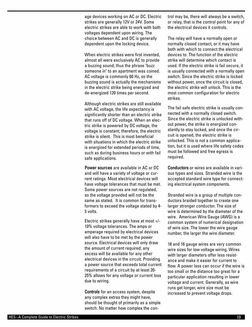
CCoonndduuccttoorrss or wires are available in vari-ous types and sizes. Stranded wire is theaccepted standard wire type for connect-ing electrical system components.
Stranded wire is a group of multiple con-ductors braided together to create onelarger stronger conductor. The size ofwire is determined by the diameter of thewire. American Wire Gauge (AWG) is acommon system of numerical designationof wire size. The lower the wire gaugenumber, the larger the wire diameter.
18 and 16 gauge wires are very commonwire sizes for low voltage wiring. Wireswith larger diameters offer less resist-ance and make it easier for current toflow. A power loss can occur if the wire istoo small or the distance too great for aparticular application resulting in lowervoltage and current. Generally, as wireruns get longer, wire size must beincreased to prevent voltage drops.
age devices working on AC or DC. Electricstrikes are generally 12V or 24V. Someelectric strikes are able to work with bothvoltages dependent upon wiring. Thechoice between AC and DC is generallydependent upon the locking device.
When electric strikes were first invented,almost all were exclusively AC to providea buzzing sound; thus the phrase "buzzsomeone in" to an apartment was coined.AC voltage is commonly 60 Hz, so thebuzzing sound is actually the mechanismsin the electric strike being energized andde-energized 120 times per second.
Although electric strikes are still availablewith AC voltage, the life expectancy issignificantly shorter than an electric strikethat runs off of DC voltage. When an elec-tric strike is powered by DC voltage, thevoltage is constant; therefore, the electricstrike is silent. This is most beneficialwith situations in which the electric strikeis energized for extended periods of time,such as during business hours or with failsafe applications.
PPoowweerr ssoouurrcceess are available in AC or DCand will have a variety of voltage or cur-rent ratings. Most electrical devices willhave voltage tolerances that must be met.Some power sources are not regulated,so the voltage provided will not be thesame as stated. It is common for trans-formers to exceed the voltage stated by 4-5 volts.
Electric strikes generally have at most +/-10% voltage tolerances. The amps oramperage required by electrical deviceswill also have to be met by the powersource. Electrical devices will only drawthe amount of current required; anyexcess will be available for any otherelectrical devices in the circuit. Providinga power source that exceeds total currentrequirements of a circuit by at least 20-25% allows for any voltage or current lossdue to wiring.
CCoonnttrroollss for an access system, despiteany complex extras they might have,should be thought of primarily as a simpleswitch. No matter how complex the con-
HES--A Complete Guide to Electric Strikes

11
bb.. Verify that the power source can handle the current draw of all electrical components in line with the power source
cc.. Verify that the power wires leading to the electric strike are of a large enough gauge to handle the current require-ments. Note: Recall that some voltage may be lost when using smaller gauge wires over long distances.
dd.. Using a multimeter, verify that the input voltage is within the recommended limits (+-10%).
ee.. Confirm that the input voltage at the installation site is DC or properly recti-fied AC.
ff.. Verify that all peripheral devices such as bridge rectifiers, SMART-Pacs, buzzers, L.E.D.s etc... are properly connected.
gg.. Check that the switch, key pad, etc., meet the voltage requirements for thesystem.
IIff yyoouu hhaavvee aannyy qquueessttiioonnss aafftteerrrreeaaddiinngg tthhiiss gguuiiddee,, ccaallll tthhee HHEESStteecchhnniiccaall sseerrvviiccee lliinnee:: 11--880000--662266--77559900
There are various electrical accessoriesthat can be used for access control sys-tems. The following are some commonlyused accessories:
• Rectifier - converts AC voltage to DC• Buzzer - provides audible indication• LED - provides visual indication• Surge Suppressor - protects electrical
devices from power surges
SSEECCTTIIOONN VVTrouble Shooting Guide
PPrroobblleemm:: IIff tthhee eelleeccttrriicc ssttrriikkee ddooeess nnoottooppeerraattee pprrooppeerrllyy
If the electric strike does not operateproperly, open the door and re-energizethe electric strike. If the electric strikeoperates properly with the door heldopen, the lockset may be pre-loading orbinding the keeper of the electric strike.
SSoolluuttiioonn:: ""PPrree--llooaadd"" iiss aannyy pprreessssuurreeaapppplliieedd ttoo tthhee kkeeeeppeerr ooff tthhee eelleeccttrriicc ssttrriikkeetthhaatt ccaauusseess iitt ttoo bbiinndd.. The horizontal rela-tionship between the lockset and theelectric strike will have to be adjusted toeliminate the binding between the bolt ofthe lock and the electric strike keeper.
PPrroobblleemm:: IIff tthhee eelleeccttrriicc ssttrriikkee ddooeess nnoottooppeerraattee wwiitthh tthhee ddoooorr ooppeenn
If the electric strike does not operate withthe door open, remove the electric strikefrom the frame, leaving the wiring con-nected, and re-energize the electricstrike. If the electric strike operates prop-erly outside of the frame, then the prob-lem may be from a tight-fitting framecutout pinching the sides of the electricstrike together.
SSoolluuttiioonn:: TThhee eelleeccttrriicc ssttrriikkee ccuuttoouutt iinn tthheeddoooorr ffrraammee nneeeeddss ttoo bbee sslliigghhttllyy eennllaarrggeedd..
OOtthheerr SSoolluuttiioonnss:: If all mechanical prob-lems have been eliminated without suc-cessful electric strike operation, checkthe following electrical problems:
aa.. Examine the power supply or trans-former to verify that the output voltage is at the listed rating.
HES--A Complete Guide to Electric Strikes
INSTALLER TIP: To quickly determinewhether an electric strike is defective,install it in a site where an electricstrike was previously installed andworked properly. Use an alternativepower source to test the electrickstrike such as a DC battery pack.
INSTALLER TIP: If the voltage is too lowto operate the electric strike, a 35 volt,220 micro-farad capacitor may beinstalled across the bridge rectifier(positive to positive, negative to nega-tive) to provide an initial boost ofpower to the unit. This is also helpful toovercome slight preloading conditions.
12HES--A Complete Guide to Electric Strikes
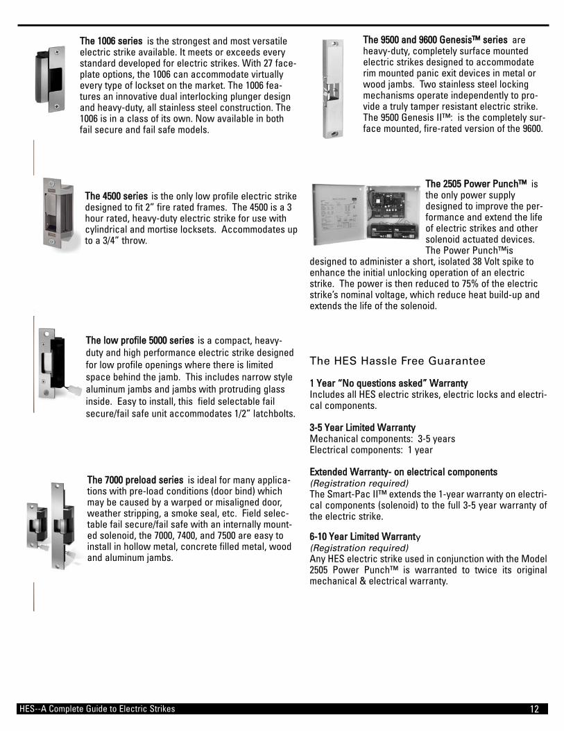
TThhee 11000066 sseerriieess is the strongest and most versatileelectric strike available. It meets or exceeds everystandard developed for electric strikes. With 27 face-plate options, the 1006 can accommodate virtuallyevery type of lockset on the market. The 1006 fea-tures an innovative dual interlocking plunger designand heavy-duty, all stainless steel construction. The1006 is in a class of its own. Now available in bothfail secure and fail safe models.
TThhee 44550000 sseerriieess is the only low profile electric strikedesigned to fit 2” fire rated frames. The 4500 is a 3hour rated, heavy-duty electric strike for use withcylindrical and mortise locksets. Accommodates upto a 3/4” throw.
TThhee llooww pprrooffiillee 55000000 sseerriieess is a compact, heavy-duty and high performance electric strike designedfor low profile openings where there is limitedspace behind the jamb. This includes narrow stylealuminum jambs and jambs with protruding glassinside. Easy to install, this field selectable failsecure/fail safe unit accommodates 1/2” latchbolts.
TThhee 77000000 pprreellooaadd sseerriieess is ideal for many applica-tions with pre-load conditions (door bind) whichmay be caused by a warped or misaligned door,weather stripping, a smoke seal, etc. Field selec-table fail secure/fail safe with an internally mount-ed solenoid, the 7000, 7400, and 7500 are easy toinstall in hollow metal, concrete filled metal, woodand aluminum jambs.
TThhee 99550000 aanndd 99660000 GGeenneessiiss™™ sseerriieess areheavy-duty, completely surface mountedelectric strikes designed to accommodaterim mounted panic exit devices in metal orwood jambs. Two stainless steel lockingmechanisms operate independently to pro-vide a truly tamper resistant electric strike.The 9500 Genesis II™: is the completely sur-face mounted, fire-rated version of the 9600.
TThhee 22550055 PPoowweerr PPuunncchh™™ isthe only power supplydesigned to improve the per-formance and extend the lifeof electric strikes and othersolenoid actuated devices.The Power Punch™is
designed to administer a short, isolated 38 Volt spike toenhance the initial unlocking operation of an electricstrike. The power is then reduced to 75% of the electricstrike’s nominal voltage, which reduce heat build-up andextends the life of the solenoid.
The HES Hassle Free Guarantee
11 YYeeaarr ““NNoo qquueessttiioonnss aasskkeedd”” WWaarrrraannttyyIncludes all HES electric strikes, electric locks and electri-cal components.
33--55 YYeeaarr LLiimmiitteedd WWaarrrraannttyyMechanical components: 3-5 yearsElectrical components: 1 year
EExxtteennddeedd WWaarrrraannttyy-- oonn eelleeccttrriiccaall ccoommppoonneennttss(Registration required)The Smart-Pac II™ extends the 1-year warranty on electri-cal components (solenoid) to the full 3-5 year warranty ofthe electric strike.
66--1100 YYeeaarr LLiimmiitteedd WWaarrrraanntty(Registration required)Any HES electric strike used in conjunction with the Model2505 Power Punch™ is warranted to twice its originalmechanical & electrical warranty.

• Use this chart to
identify ANSI locks
and to select which
HES electric strike
will provide the cor-
rect alignment to
release each lock,
(in both new and
retrofit ANSI 4-7/8”
jamb preparations).
• Use this chart to
determine which
HES electric strike
matches a specific
manufacturer’s lock.
HES electric strikes are all non-handed and designed forinstallation in hollowmetal, concrete filledmetal, aluminum and wood jambs.
Cylindrical locksets.
All locks with centerlined latchbolts.
All manufacturers.
1006J- Up to 1” throw45005000 - Up to 1/2” throw5700 - Up to 1/2” throw7001, 7002, 7501, 7505Up to 5/8” throw
Accurate, Arrow,Baldwin, Falcon (1991&earlier) Marks, Omnia,PDQ
1006K4500
Best 1006KM4500
Sargent (7700 & 8100series), Schlage, Yale 1006KD
Mortise lockset with adeadlatch positionedbelow the latchbolt.
Almet, Corbin/Russwin,Falcon (1992 “M”Series), Sargent (7800,8200, & 9200)
1006KM4500
Accurate, Arrow,Baldwin, Best, Corbin,Falcon, Marks, Omnia,PDQ, Russwin
1006N1006A1006H
Sargent (7700 & 8100series), Schlage, Yale
1006ND1006AD1006HD
Baldwin, PDQ 1006T1006HTD
SargentSchlageYale
1006TD
Mortise lockset with a1” deadbolt and a dead-latch positioned belowlatchbolt.
Accurate, Almet, Arrow,Baldwin, Best, Corbin,Falcon, Marks, Omnia,PDQ, Russin, Sargent(7800, 8200 & 9200series)
1006NM1006AM1006HM
Rim mounted exitdevice with up to a 3/4” throw.
Adams Rite, AmericanDevice, Arrow, JacksonDormatic, Monarch,Precision, Sargent, VonDuprin, Yale
7000-83, 7000-786,7000-78995009600
HES electric strikes aredesigned to be installed inaccordance with theANSI/BHMA A156.5 4-7/8”jam preparation. Whenaccommodating a cylindri-cal lock, the electric strikeis to be installed centerlineto centerline. When acco-modating a mortiselock,the centerline of theelectric strike is to beinstalled 3/8” above thecenterline of the mortiselock.
NOTE: This chart is offeredas a convenience only.HES assumes no liabilityfor the differencesbetween items compared.When compatitibility is aconcern, contact HES forapplication assistance.
Mortise locksets witha deadlatch positionedabove the latchbolt.
Mortise lockset with a1” deadbolt without adeadlatch.
Mortise lockset with a1” deadbolt and a center positioned deadlatch.
10/2003
ANSI LOCK DESCRIPTION MANUFACTURERHES
ELECTRIC STRIKES
HES--A Complete Guide to Electric Strikes 13
EElleeccttrriicc SSttrriikkee//LLoocckk CCrroossss RReeffeerreennccee CChhaarrtt