Embed Size (px)
Citation preview

High Head Hydropower Components
1. HIGH HEAD HYDROPOWER DEVELOPMENTS In high head hydropower development three main types can be distinguished: 1. Diversion canal type (run-of-river operation) 2. Diversion tunnel type plant (storage project, less frequently run-of-river operation) 3. Dam station development The main parts of the high head diversion canal type plant are: • weir and appurtenant structures • canal intake • headrace and appurtenant structures or free-flow tunnel • headpond with spillway and gate or valve chamber • penstock or a pressure shaft • powerhouse or underground station • tailrace • switchyard or underground switchgear equipment The water of the canal is diverted by a low weir, a high weir cannot be utilized to increase the operating head. The intake must be located at the elevation of the riverbed to ensure water inflow into the canal. This kind of high head development is used in run-of-river operation, in special cases a pondage can be achieved to some extent by capacity of the pond. The head is created by utilizing the difference between the gradient of the river valley and the power canal, so that in mountainous area the power canal may sometimes become very long. The general layout of a diversion canal development can be seen in the following figure:
Fig. 1.1: High head diversion canal development [1]
1

High Head Hydropower Components
The second type of high head developments are plants fed by a pressure tunnel (Fig 1-2). This type is generally used for the utilization of very high heads. Following are the main parts: • dam or weir • intake or headwork • pressure tunnel • surge tank • penstock (with valve chamber) or pressure shaft • external powerhouse or underground station • tailrace or tailwater tunnel • switchyard or underground switchgear equipment This type of high head development shall be considered at favourable dam sites with long bends downstream, where a shortcut can be established by drilling a tunnel. Geological conditions will be prevailing for this.
Fig. 1.2: Pressure tunnel development [1]
2

High Head Hydropower Components
If the powerhouse is located close to or even within a high dam structure as shown in Fig 1.3, the development is called plant with concentrated fall or dam station development. The maximum head for the power station approaches the height of the dam. For this reason, this type of development covers smaller available heads than the aforementioned types. This kind of development consists of the following main parts: • water intake, on the upstream face of the dam • pressure conduit, transversing the dam body or bypassing the dam through rock • powerhouse • switchyard
Fig. 1.3: Concentrated fall development [19] Regarding the generated power it has to be mentioned, that the diversion canal type plant is governed by the available water in the river. Therefore this type can be called a high head run-of-river plant. However, the two latter types have storage capacities and may be referred to reservoir power plants. A more detailed discussion of different power development layouts can be found in the part “Layout and Sizing”, where possibilities will be explained with the help of several examples. 2. CIVIL COMPONENTS 2.1 HEADWORK AND APPURTENANT STRUCTURES 2.1.1 HEADWORK Headwork of high-head hydropower project, in this manual, is defined as term for the main structures which are located at the river or stream for the diversion of water or to control water to be used for the specific need of project. This may include either weirs or dams and all associated appurtenant structures relevant to these structures; such as spillway, energy dissipaters, aprons, grouting, gates, etc. Headwork is rather a general constructional term used for all structures that are built across the river from where the water is diverted to produce energy.
3

High Head Hydropower Components
Selection of an appropriate location for the headwork is one of the major parts in the planning of high-head hydropower. Despite the constraints by different factors, there have been, fortunately, numerous solutions to the selection of headwork structures. This section provides an overview of the characteristics of the individual structures which may guide to consider structures appropriate for the particular location. The selection of structures of the headwork depends on the main types of high-head development. According to E. Mosonyi, there are three main types of high-head hydropower development [1]: 1. Diversion Canal Development 2. Diversion Tunnel Development 3. Concentrated Fall Development The description of the major components of above mentioned development alternatives has been dealt briefly. In this module appropriate structures prevalent to different components of the hydropower are described in the following: 2.1.2 HEADWORK FOR DIVERSION CANAL DEVELOPMENT 2.1.2.1 GENERAL Headwork for diversion canal development in high-head hydropower is essentially provided by the low weir. A weir is a low-level water retaining structure which is usually constructed across a river or a stream for the purpose to divert part of water into the waterway. The waterway may be free flow channel, low pressure or high pressure tunnel etc. The use of high weir in this case may not be justified because the head created by storing water behind it cannot be utilized to increase the operating head [1]. The difference in elevation between the water level in the canal and the retention level will be lost. Being small in size, there are no constraints regarding topographical or geological conditions for the selection of the low weir. Environmentally, this option is less detrimental. However, wherever the topography and prevailing geology is favourable for high weir or dam installation, the diversion canal development with low-weir may be discarded for economic reason [1]. Since the output of diversion canal development option is mainly governed by the discharge available in the river, it is mainly referred to the run-of-river (ROR) plant. It may also have some daily peaking capacity with small storage. 2.1.2.2 STRUCTURES Fixed Crest Gravity Weir It generally consists of three parts [2]: • body of weir with overflow and bottom outlet • stilling basin • upstream/downstream graded filter to prevent seepage
4

High Head Hydropower Components
Fig. 2.1: Fixed crest gravity weir This weir (Fig. 2.1) may be constructed on permeable, semi-permeable and impervious layer of the river stretch. In case of permeable layer, all three parts of the weir should be considered. For semi-permeable, only stilling basin and the body of weir should be considered. In case of pervious layer, only the body of weir is considered and consequently the quantity estimate is done. The advantage of this weir is that it does not require mechanical parts to control flood and hence, it is relatively cheap in construction. Gravity weir with movable crest This weir (Fig 2.1) is also called a barrage. This weir consists of the same appurtenant structures as the fixed crest gravity weir. In addition to this the body of weir is equipped with a movable crest e.g., flap gates to control the flow. The lateral walls at the river shores and a gate operating house also have to be considered for the layout. In some cases, for reasons of weir inspection or access, a bridge over the weir also has to be considered. Similar to the fixed crest weir, this type of weir is suitable for any prevailing geological site condition and the appropriate parts of the layout of weir should be considered for the quantity estimate. The advantage of this weir is that additional storage is possible during normal operating conditions and provides some economy in power generation [2]
Fig. 2.2: Gravity weir with movable crest [19] Tyrolean Weir This weir is most convenient for high gradient and heavy gravel laden mountainous river or stream (Fig. 2.3). It is constructed directly on the bottom of the channel. It is particularly suitable for a narrow channel where the space for overflow and intake is not sufficient. It has mainly two parts.
5

High Head Hydropower Components
• bottom intake with bottom rack • fixed crest weir The first part consist of • the body of the Tyrolean weir with a collecting canal • the bottom rack sheltering the canal from gravel intrusion • stilling basin depending on the geological condition of riverbed. The second part of the Tyrolean weir is similar to the fixed crest weir as mentioned above.
Fig. 2.3: Tyrolean weir 2.1.2.3 CONSTRUCTION MATERIALS The construction materials for the above mentioned weirs vary greatly depending on the prevailing local conditions (e.g., labor, local materials, transportation etc.). The weir may be constructed from: • concrete or reinforced concrete • stone or brick masonry • stone or boulder filled gabion structure • Timber or steel cribs, filled with cock in combination with steel or concrete to minimize
seepage • inflatable rubber or synthetic fabric dams • earth or rockfill • rollcrete (roller compacted concrete) • locally available low cost materials such as timber with planks joined together, bamboo,
bundle of bushes, haystack or straw-bale, sand bags etc. These materials are usually cheaper but constructed for temporary purpose which requires periodic maintenance and can be handled by local people. This type of material is generally used for small scale hydropower plants.
In some cases, a fish passage or ladder may also be necessary to meet the environmental requirement. 2.1.3 HEADWORK FOR DIVERSION TUNNEL DEVELOPMENT 2.1.3.1 GENERAL The headwork for diversion tunnel or plant fed by pressure tunnel is usually arranged with the high weirs or dams. The reason is that the high water retention level is a main condition for the
6

High Head Hydropower Components
choice of pressure tunnel. The tunnel intake invert level should be located at the lowest possible level of the reservoir to ensure the greatest useful storage. This arrangement should be in accordance with the sediment flow and possibility of delta formation behind the dam which may block the intake and allow sediments to enter into the tunnel and which is highly undesirable in case of high-head hydropower development where the velocity of flow is very high. 2.1.3.2 LOW PRESSURE TUNNEL It may some times be preferable to build a low pressure tunnel under certain topographical and geological conditions which is favourable only for low weir or dams (e.g., tunnel storage alternative). In this case, the tunnel may be operated under free flow condition and should, therefore, be regarded as diversion canal type development [1]. 2.1.3.3 CONSIDERATION OF GEOLOGICAL FAULT AND SEISMISITY As this arrangement is most likely for storage type plant (SP), the site for headwork should be located in such a way that ensures adequate natural storage volume behind it. In such cases the entire reservoir area must be adequately watertight to avoid undue leakage [4]. For this reason the sites prevailing to geological faults and seismic zone should be avoided as far as possible for safety and cost reason. 2.1.3.4 STRUCTURES Structurally, the fixed crest and movable crest gravity weirs are also applicable for high weir. Since the function of the high weir is to create a high retention basin, these weirs should be founded on the bed rock and be stable enough to resist all imposed load to it. The Tyrolean weirs are functionally not suitable for this type of development. Dams suitable for diversion tunnel type of development are similar to the third type of development i.e., the dams for reservoir and are dealt separately. Design of such structures is dealt in the chapter Engineering Design of this manual. 2.1.3.5 CONSTRUCTIONAL MATERIALS Except the constructional materials considered for the low cost temporary structures, all construction materials mentioned above are suitable for this type of headwork. However, appropriate safety should be taken into consideration while selecting the construction materials. 2.1.4 HEADWORK FOR CONCENTRATED FALL TYPE DEVELOPMENT 2.1.4.1 GENERAL This type of development is essentially arranged with a high dam installation with powerhouse closely located to the dam or within it. This arrangement is principally similar to low-head hydropower plant. In this case the maximum head is mainly created by the height of the dam. The diversion tunnel type and the concentrated fall type developments are, in economic term, referred as storage type power plants (SP). In such cases the fluctuation of river flow has no or negligible influence on the power generation. In this respect the tunnel development with large reservoir and high head is most valuable option [1]. Most decisive criteria for the selection of the last two types lie on the energy economy of the system, as well as the topographical situation where natural head, to some extent, is to be augmented by means of artificial head. Hydrological and geological factors are decisive for the choice of the dam structures, which is dealt here subsequently. 2.1.4.2 DAMS According to the used construction materials there are two types of dams: 1. Concrete Dam (CD) 2. Embankment Dam (ED)
7

High Head Hydropower Components
Concrete Dams (CD) These are rigid structures designed to carry imposed loads into the foundation by compression. Therefore, they are generally constructed on rock foundation. Small concrete dams are also suitable for gravel foundation. The tensile stress is reduced or eliminated by careful shaping of the concrete structure. Bi-pass of river during construction may be possible through the openings in the dam or the dam could be constructed in stages so that the river diversion is possible via river channel. This will reduce the necessity to construct expensive river diversion tunnel. Spillway and fish passage are also possible to incorporate in this type of dam. There are various types of concrete dams which could be used to tailor the prevailing specific site conditions: Concrete Gravity Dam (CGD): It is basically two dimensional concrete structure capable of resisting imposed loads through sliding friction due to its weight acting on the foundation. It is the most often used structure for making impoundment and may be located in a moderately wide section of river. It should be founded on bedrock or on the foundation with special geotechnical treatment as shown in the Fig. 2.4.
Fig. 2.4: Concrete Gravity Dam and its layout • Curved Concrete Gravity Dam (CCGD): This is same as above but structurally curved to fit
into relatively narrow dam site (Fig. 2.5). In this case the abutments also take some load imposed to the dam by arch action. It is therefore sometimes known as concrete arch gravity dam (CAGD).
8

High Head Hydropower Components
Fig. 2.5: Curved concrete gravity dam • Arch Dam (AD): Arch dam is useful to construct at very narrow and steep valley of the river.
The length of the arch to dam height ratio which is about 4 to 6 should be considered as practicable. It is a three dimensional structure and thus transfers the imposed load to abutments through arch action (Fig. 2.6). It has also possibility to transfer some of load to the bottom foundation through cantilever action. Thus it reduces the volume of the dam considerably as compared to concrete gravity dam (CGD) of same height and width. It is cheaper and safer than CGD and may be built on U-shape valley.
9

High Head Hydropower Components
Fig. 2.6: Arch Dam, Cross - Section
Fig. 2.7: Arch Dam, Plan • Buttress Dams (BD): Buttress dams are the retaining structures which are capable to
transfer the imposed load on its upstream inclined membrane to the bottom foundation via buttresses supporting the membrane (Fig. 2.8). The main idea behind the evolution of this type of structure is to: • reduce the uplift pressure to a practical minimum ( the main disadvantage of CGD or
AD) • exploit hydrostatic pressure on upstream face • utilize the strength of materials.
10

High Head Hydropower Components
Fig. 2.8: Buttress Dam [19] These dams may be used in very broad valleys and may be used for narrow sites. A gently sloping regular valley offers greater scope for economy by adoption of constant mean spacing of buttresses. The most common buttresses are shown in Fig.2.9. • T-head • Doppel T-head • Diamond-head • Round-head
Fig. 2.9: Various types of Buttress dams Despite its usefulness, buttress dams have some major problems in design and
construction. Therefore their choice should be done with care. These dams are selected only in the case where the sites are not economically suitable for other types of dams. For example, if grouting is difficult in rock foundation then buttress dam may be used.
Embankment Dams These dams are some how a replication of natural dams. With some engineering treatment, they are very useful to be constructed as retaining structure on fairly permeable foundation. Embankment dams should be heavy enough to resist applied loading. The materials for impervious core and the body are selected so that it reduces the hydraulic gradients within the embankment foundation. The main advantage of embankment dams is the use of local construction materials, which requires less sophisticated technology. Hence these dams are cheaper in construction and maintenance. Being cheaper, they are in use in very wide sections of river course where other structures are not suitable for cost reason.
11

High Head Hydropower Components
Foundation requirements in embankment dams are less than in concrete dams. Raising an embankment dam height is also easier and cheaper than concrete alternatives. Embankment dams are exceptionally suitable for the construction of coffer dams. Special care should be taken for the construction of embankment dam in the zone of high rainfall and seismicity. According to materials used and construction techniques, there are two types of Embankment dams: • Rockfill dams:
This dam type is usually suitable for small dams, however with some innovation in constructional methods (such as placing large rocks with rise instead of dumping), high rockfill dam may also be possible. Rockfill dams are founded on the gravel bed, but are not suitable for fine sand and clay foundation. These dams are exceptionally suitable for wide valley and areas, therefore, competitive with other alternatives. Rockfill dam is classified into two categories:
• Impervious facing Rockfill dam: the impervious facing of concrete or asphalt is placed on the upstream slope (Fig. 2.10). In this case the impervious face directs the water pressure downwards. This method is useful in exploiting the friction between the rockfill and the bedrock to resist sliding. The design of flexible facing is the main difficulty in this type of dam.
Fig. 2.10: Rockfill Dam with impervious face upstream and with central core • Central core rockfill dam: This type of dam is similar to the central-core earthfill dam. It is
less subject to the temperature stresses during drawdown period. However, it is difficult for inspection and repair due to lack of access [6].
• Earthfill dams: As the name suggests these dams are constructed with the soils excavated from banks of inundated zone (if suitable for fill) or from borrow areas. These dams are easy to construct and may be suitable for permeable foundation. Cut-off is an important element of embankment dams in case of deep strata of pervious foundation to reduce the seepage loss. Special care must be taken to select embankment dams in seismic zone. Slope protection, material selection for impervious core and its design are the major concern of this type of dam. The earthfill dams should be prevented from the internal erosion and piping of underlying materials due to leakage by a properly designed drainage system. Rapid draw down of reservoir is not permissible in earthfill dams. Bi-passing of river during construction requires tunnels or culverts which are regarded as the disadvantage of this type of dam. Sometimes the shaft spillway may be incorporated with the bi-pass tunnels or culverts. However, the size of these aqueducts may not be sufficient to pass the high flood discharge. Since overtopping is not allowed for the earthfill dams, necessary freeboard is to be provided.
12

High Head Hydropower Components
Lack of spillway may cause the complete failure of earthfill dams. The arrangement of spillway for the dams has been discussed in the section “Spillway”. If foundations are suitable and if adequate crest length can be provided, a concrete spillway may be provided. Alternatively, a sidelong spillway and spillway channel may be provided. Spillway should be founded on the bedrock and an approach channel to the spillway should also be provided. The earthfill dams are broadly classified into four categories: • Homogeneous-fill dams: Still in use in the absence of sufficient free-draining fill. Fig.2.11
shows various types of homogeneous-fill dams.
Fig. 2.11: Types of homogenous-fill dams
• Zoned-fill Dams: The purpose of zoned-fill dams is to eliminate the voids and fissures which form the main seepage paths in uncompacted clay fill. Fig. 2.12 shows various forms of the zoned-fill dams [4]:
Fig. 2.12: Various forms of zoned-fill dams
13

High Head Hydropower Components
• Dams with a Partial Cut-off: These types of dams are used when due to geological condition, the positive cut-off is not viable economically. Fig. 2-13 shows some forms of partial cut-off dams.
Fig. 2.13: Dams with partial cut-off • Hydraulic-fill dams: It is a special type of zoned-fill dams which is constructed by
pumping fill materials from borrow pits with stream of water and spreading it over the dam site. Due to difficulty in design, it is seldom used.
2.1.5 RESERVOIR 2.1.5.1 GENERAL High-head hydropower relies on the naturally available head. However, in most cases, high-head hydropower projects are located in the areas where rivers, streams are characterized by low flow during dry period and high flow during wet period. Hydroelectric project drawing water directly form a stream may not be able to satisfy the demands of its consumers during low flows. In this case, it may sometimes be necessary to provide water storage by impounding behind a dam or a weir on such rivers or streams. The main purpose of storage is to stabilize the flow of water in the stream and to provide dependable min. flow in low flow period to meet the demand. It also increases hydrogenation by improving plant’s hydraulic head and machine efficiency. There are mainly two types of reservoirs: 1. Mainstream reservoir: reservoir which is directly located along the river upstream of dam. 2. Offstream reservoir: reservoir which is located outside of the river by means of excavating a
large portion of land (e.g., reservoir for municipal water supply).
In this manual, we mainly deal with the planning and design of mainstream reservoir for hydropower storage purpose. The mainstream reservoir has the advantage of releasing stored water at any time of need. Hydrologically, large hydro reservoirs are designed for long period storage to carry over from wet to dry years. Small storage impounded by weir or pumped storage reservoirs need only daily or weekly flow regulation. Pure run-of-river have no or very little storage. Structurally the following important factors must be considered in a reservoir planning: • size, sitting, rim stability, seepage, seismicity, bank storage, evaporation, sedimentation,
and other associated structural works (i.e., recreational and service facilities). • storage capacity and reservoir operation is an important factor in design. • environmental impacts (upstream inundation and downstream water right problems,
migration of fish etc.) • trade-off among engineering, environmental impacts and economics must be made.
14

High Head Hydropower Components
2.1.5.2 ELEMENTS OF RESERVOIR Following are the main elements of a reservoir (Fig. 2.4):
Fig. 2.14: Elements of reservoir Minimum pool level (MPL) is the lowest elevation to which the useful storage may be drawn down under normal conditions. This level is usually fixed by the lowest outlet in the dam. For example it is the level which determines the inlet level of an intake and thereby the conditions of operational efficiency for the turbines. Water held below minimum pool level is called dead storage. Normal pool level (NPL) is the normal operating level of the reservoir determined by the service need. The storage volume between the minimum and normal pool levels is called the useful or service storage. Normal pool level (flood) is the maximum elevation to which the reservoir surface will rise during ordinary operating conditions. For most cases, it is determined by the elevation of the spillway crest or the top of the spillway gates. Design flood level (DFL) is the level which is determined by the requirement of flood control. The storage between this level and the normal pool level (regular flood storage) is called surcharge storage. It exists only for short duration and cannot be held for later use. Free board level is the highest level of a dam required to protect from the overtopping by water. It is determined by summing up the height due to wave run-up and wind setup above the pool level during design flood (surcharge). An additional safety factor is also added depending upon the class of the dam. Normal storage is the storage within the normal pool level (regular flood storage) and the lowest level of the reservoir. Total storage is the storage between the pool level during design flood (surcharge) and the lowest level of the reservoir. Reservoir volume is the maximum storage capacity or the reservoir at the freeboard level. Due to the permeability of the riverbanks, some amount of water is “stored” in the banks and is called bank storage. This storage increases the capacity, however it is not relevant to the hydropower. Therefore, it is not dealt here.
15

High Head Hydropower Components
2.1.5.3 STORAGE CAPACITY The storage capacity of a reservoir for hydropower is its most important physical characteristic. The capacity of a reservoir of regular shape can be calculated with the formulas for volumes of solid [Linsley and Franzini, 1979]. Capacity of reservoir in natural streams and rivers must usually be determined from an area capacity curve based on topographic maps or field surveys (Fig.2.15).
Fig. 2.15: Area-Elevation curve
Surface Area (m²)
Storage (m³)
Storage Area
El. (m)
Design of storage capacity depends on the amount and variation of natural stream flow and fluctuating energy demands. Therefore, the main aim of the design of storage capacity for hydropower is to adapt the fluctuating stream flows to variation in functional demands (i.e., electric load etc.). The estimate of electric energy demand is based on the future population growth and the economic activities of the load center. Following are the characteristics of demand that should be considered during the design of storage capacity: • firm energy demands • secondary energy demands • peaking energy demands • reserve capacity demands Apart form the water retention function during high flow and release during drought, storage capacity also has the function of high flood control to avoid the risk of dam break and downstream hazard (e.g., PMF or GLOF events). This includes the consideration of design of surcharge flood storage to determine the total reservoir capacity, dam height, length of spillway, capacity of reservoir outlets etc. The amount of storage needed to supply demand can be determined form a mass curve, a flow hydrograph, and/or a duration curve which can be obtained from the study of river hydrology of the given river and streams. Following are the list of storage capacity design for nonhydro purposes. The detailed description of these purposes is out of scope of present manual, hence will not be dealt further. • flood control • irrigation requirements • Municipal and Industrial uses of water • navigational requirements • recreational requirements (boating, fishing, swimming) • fish and wildlife requirements
16

High Head Hydropower Components
2.1.5.4 RESERVOIR YIELD The most important aspect of storage reservoir is an analysis of the relation between yield and capacity. Yield is the amount of water which can be supplied from the reservoir in a specified interval of time. Yield is dependent upon inflow and will vary from year to year. The safe, or firm, yield is the maximum quantity of water which can be guaranteed during a critical dry period. The critical period is the period of lowest natural flow on record for the stream. Since firm yield can never be determined with certainty, it is better to treat yield in probabilistic terms. The maximum possible yield equals the mean inflow minus evaporation and seepage losses. As variability of the flow increases, the required reservoir capacity increases. The selection of reservoir capacity is dependent on the acceptable risk that the yield will not always be realized. Water available in excess of safe yield during periods of high flow is called secondary yield. It has an economic value in hydropower development. Hydroelectric energy from secondary yield may be supplied to large industries on a “when available” basis. Energy commitments to domestic users must be on a firm basis and should not exceed the energy which can be produced with the firm yield unless thermal energy is available to support the hydroelectric energy. The decision is an economic factor based on costs and benefits for various stages of design. Another important aspect of the reservoir design is the computation of the water surface profile throughout the length of the reservoir. This information is useful in order to know the land requirements and calculation of compensation of property damages. The shape of water surface profile can be determined using methods for non-uniform flow (see [7]). 2.1.6 POWER INTAKE 2.1.6.1 GENERAL A power intake is the structure from where desirable water is taken into the waterways for the power generation. Proper location of power intake structures is important in the view of low cost and smooth operation of the power plant. The intake may be incorporated within the body of a concrete dam (concentrated fall scheme) or weir (Tyrolean type) or may be located separately outside of the dam (usually, in case of embankment dams). Besides the water supply, one of the major functions of the power intake is to minimise the amount of debris and sediments carried by the incoming water. It also controls the flow of water which is admitted under all stream flow conditions. For this purpose, several kinds of gates may be used. If the water flow is not controlled at the intake, excess water may damage the power canal or forebay and can be disastrous for other components of the project (viz., penstock, powerhouse etc.). Therefore, proper design of the intake is essential for trouble-free operation of the whole system of waterways. However, proper location of intake along the stream reduces the burden placed on the intake itself [1]. An adequate initial planning is necessary to place the intake where it will be protected form excess water and debris which might otherwise be funneled into it during flood period. As said earlier, an intake may be located separately or may be incorporated in the dam or weir body. In the latter case the over all rule for the selection of the location of weir or a dam is applicable to an intake. However there are some functional differences between them as follows: • an intake must have entrance with minimum head losses, • it should prevent bedload and flowing debris intrusion into the canal or tunnel, • it should allow to deflect and flush bedload accumulated in front of the weir and inlet, • it should protect canal or tunnel from floating debris. Owing to some particular differences, mainly hydraulic requirements, in this section also we will mainly deal with the selections of intake structure according to the type of hydropower development.
17

High Head Hydropower Components
2.1.6.2 INTAKE FOR DIVERSION CANAL TYPE DEVELOPMENT This layout requires an intake integrated in a weir body or placed laterally. The essential design feature and structural arrangement of an intake structure for high head is also governed by the principles applicable for intake of low-head hydropower [1]. However, the difference among them is that the settling space available between the inlet section and the intake gate at low-head intakes is insufficient for high-head developments. Unlike the low-head hydropower development where the velocity in the river is low the high-head hydropower development essentially requires settling basins or sand traps to get rid of high sediment load of mountainous rivers. 2.1.6.2.1 LATERAL INTAKE Depending upon the site conditions, the main features of a lateral intake for the diversion canal type developments are: 1. the inlet section with sill, coarse trashrack and sometimes with skimmers or floating booms 2. the inlet gate with gate house and the transition section 3. the spillways 4. the settling basin with fine screen and the sand-flushing canal. Gates and spillways are meant to control the quantity of inflow whereas the trashracks, skimmer or floating booms and settling basins are used to control the quality of water entering into the canal. Although a stream can be tapped virtually anywhere along its length, careful sitting of the intake is necessary to avoid future problems. Following factors should be taken into consideration while sitting an intake [8]: • the nature of the streambed: this factor is required to establish the elevation of the intake. If
an intake is selected without a permanent dam or weir across a stream (in case of micro or mini hydro project), erosion might lower the elevation of the streambed and eventually prevent the water entering into the intake. To avoid this risk, the intake should be located at a point along the stream where the river bed is relatively permanent, for example:
• a spring with small catchment having constant year round flow. • a stream with bedrock at the bottom, • stream stretch with smaller gradient.
• bends along the stream: E. Mosonyi suggests that on mountain rivers carrying heavy
sediment load the ideal site for an intake would be on the concave side (b) of the river even if this side is otherwise less favourable [1]. In such case the inlet should be inclined approximately 30o to the flow to avoid the vortex formation at the inlet. However, care must be taken to protect the structure during high flood for the reason that this side is highly prone to erosion.
18
River Bed Water Surface

High Head Hydropower Components
a) in bends, b) on straight stretches, c) spiraling flow
Fig. 2.16: Typical layouts for intake (after R. Müller in [1]) Fig. 2.6a shows some examples of locating an intake site with respect to the configuration of river bends whereas Fig. 2.6b refers to straight stretches. The main idea behind these solutions is to produce by means of suitable structures a spiraling flow (Fig. 2.6c) and to locate the intake works at the concave side thereof [1]
19

High Head Hydropower Components
• natural features along the stream: In small hydropower projects it is sometimes possible to protect the intake from flood waters by the natural features found along the stream such as intake located behind the big boulder on the stream or natural branching of the main river etc. Fig. 2.7(a) shows the intake placed under the boulder which may protect from the flood waters and also prevent the debris intrusion into the canal. Similarly Fig. 2.7(b) shows another possibility of the use of the natural feature along a stream where naturally placed boulder restricts flow into branch off mainstream protecting from high flow.
Inlet to Power Canal Under Boulders
Island
Power Canal
Several Stones Serving as a
Diversion Weir
Naturally Placed Boulders Diverting Flow into Branch of
Main Stream
(a) Intake under the boulder (b) Intake at branch off main stream
Fig. 2.17: Natural features along the stream (after Inversin) • competing uses for water: In some countries the primary use of water is for drinking,
irrigation and fisheries, etc. (e.g. in Pakistan). In this case the downstream water use should be kept in mind while siting an intake to a hydropower scheme where sizeable portion of water is to be taken. If the flow required for power generation might affect irrigation, several options as described by Inversin (1986) are available to accommodate both uses:
• parallel operation of irrigation and power plant when both need a major portion of water
and power generation in times when water is not needed for irrigation. • storing excess water than used for irrigation and using it for power generation. • avoiding any interference with the irrigation canals of an area by siting a hydropower
scheme between two consecutive irrigation intakes along a river as shown in Fig. 2.18 by incorporating a power scheme in series with an irrigation system so that power can be generated without having an adverse impact on irrigation. This option is mostly applicable for the low-head micro hydropower scheme or may be applicable in the case of high gradient mountainous rivers for high head.
20

High Head Hydropower Components
21
Fig. 2.18: Sitting a hydropower scheme between two consecutive irrigation intakes (after Inversin) • ease of accessibility: While sitting an intake to hydropower scheme, it is always necessary
to keep in mind the accessibility to the site for construction and later maintenance purposes. 2.1.6.2.2 VERTICAL DIVERSION TYPE INTAKE The vertical diversion type structures are widely used in the small mountain brooks and rills either to directly feed power stations or to collect water for reservoirs from neighbouring drainage basins where other types of intake structures are unacceptable on economic reason. Because of its relatively easy design and construction, the operation and maintenance of this type of intake is also easy. Fig. 2.19 shows a special design of one of the various variants of a vertical-diversion intake, the so called Tyrolean Weir, developed by the Tyroler Wasserkraftwerke AG (TIWAG), Austria. In Fig. 2-20 and Fig. 2-21 similar structures can be seen. The water flowing over the racks of fixed weir drops into a cross-flume which conveys flow through a bend into the settling basin. The racks usually trap gravel and cobbles.

High Head Hydropower Components
rolean weir in Austria [22]
Fig. 2.19: General layout of a vertical-diversion type intake (After H. Drobir in [1]) [20]
Fig. 2.20: Ganeu Alpe Tyrolean weir, Austria [21]
Fig. 2.21: Ty2.1.6.3 INTAKE FOR DIVERSION TUNNEL AND CONCENTRATED FALL DEVELOPMENT 2.1.6.3.1 GENERAL Since the diversion tunnel or concentrated fall development involve a storage reservoir, the level of the intake opening is governed by the maximum drawdown of the reservoir. The intake requires to be arranged so that it is sufficiently far below the minimum reservoir level to ensure that it is adequately submerged under such conditions to prevent air being drawn into the tunnel by vortex formation. The low-level intake has the advantage that it is less likely to be affected by floating trash and thick ice slab. However, as this requirement is provided, the intake should be located as high as possible for the economy of construction and maintenance [9]. 2.1.6.3.2 FORMS OF INTAKE FOR DIVERSION TUNNELL
22

High Head Hydropower Components
According to E. Mosonyi [1] there are the following basic forms of intake structures for diversion tunnel type or concentrated fall development: Shaft headwork: Fig.2.22 shows the general arrangement of shaft headwork where the flow into the pressure tunnel is controlled from a shaft intersecting the tunnel. The entrance of the shaft is located above the highest storage level. Since there is no water inside the shaft during operation, this is also called a dry type intake. The cross-sectional areas of the intake should be gradually reduced from a maximum at the entrance down to the area of the tunnel so that the velocity of the water entering it is gradually accelerated. The screen is installed at the entrance of the gradually enlarging tunnel-shaped intake.
Fig. 2.22: Shaft headwork of a pressure tunnel development [1] The shaft may be omitted if the range of water level fluctuations is small. (Fig. 2-23)
23

High Head Hydropower Components
Fig. 2.23: Intake of a pressure tunnel development without shaft To cope with the particular topography of the very narrow valley stretch of the Kabul River in Pakistan, a sharply curved funnel-shaped intake is adapted for the medium-head Warsak plant (Fig. 2.24)
Fig. 2.24: The fan-type intake of the Warsak dam-station project. Intake tower: Intake tower is used in case of great discharges because of the favourable hydraulic conditions attainable by the properly shaped inflow mantle [1]. Flow into the tower is generally controlled by a number of small gates or by a cylindrical valve.(Fig. 2.25)
Fig. 2.25: Intake tower Subsidiary Intakes:
24

High Head Hydropower Components
These types of intakes are used to augment flow to the main reservoir by tapping adjacent streams at high level and leading the water by open channels or closed culverts to the reservoir. The design of this type of intakes is similar to those already mentioned above. Alternatively, if the topography allows, it may be possible to feed single power plant from different reservoirs and brooks with the help of subsidiary intakes. In such case, various vertical shafts are required to connect the tunnel (Fig. 2.26).
Fig. 2.26: Intakes from several reservoirs and brooks [19] 2.1.6.4 SIZING OF INTAKE STRUCTURE Sizing of intake structures and the choice of the site should be done depending on the minimum discharge Qo capable of inducing bedload movement. The design should be in such a way that less sediment intrusion is possible. The ratio of the plant discharge capacity Qp and of the limit discharge Qo is one of the factors governing the design of the intake. In case of pressure tunnel headrace, care must be taken to determine the minimum operating level to avoid the vortex formation in the inlet 2.1.6.5 INTAKE EQUIPMENT 2.1.6.5.1 INTAKE TRASH SCREENS Screens are necessary to provide in all intakes which intercept the debris. In many instances, it is also necessary to intercept the fish and smols to pass through the intake. Coarse screen function as the interception of debris and fish and is known as Trash screen. For the smols, a separate fine screen (smolt screen) has to be provided behind the coarse screen. Except for some occasional design, the Trash screens are fixed in place. Smolt screens, on the other hand, need only to be in operation during the months when the smols travel downstream. During rest of the time, they are removed, cleaned, painted and stored in safe place. Screens are to be strongly constructed, because they are subjected to the water pressure difference and also from the floating debris and ice load. The screen bars are usually prefabricated from mild-steel flats suitably spaced for particular purposes. In cold regions and in glacial areas of high mountains, ice problems near the intake may arise and block the proper functioning of the intake. Some heating arrangements should be provided on the trash screen to protect it from icing. Since the heating of large area is relatively
25

High Head Hydropower Components
expensive, the alternate solution may be to provide compressed air from the bottom of the trash screen which may blow away the floating ice and also eliminate the icing around it. 2.1.6.5.2 INTAKE TRASH RAKES Trash rakes are provided to remove the trash accumulated at the intake screen. In small installation the trash can be removed by simple hand tools. However, in medium and large scale hydropower installations mechanically operated trash removers are commonly used (Fig. 2.27). Most rakes work in a satisfactory way when the screen bars are inclined at a slope of one horizontal to three vertical [9].
Langweid Power Station following Container
Fig. 2.27: Mechanically operated trash rakes. [24] A number of different forms of mechanical rakes have been devised but they all depend on the principle of dislodging on the downward, travel the trash attached to the screen, then engaging the dislodged trash and raising it on the upward travel. The amount of trash to be intercepted will depend on the nature of the vegetation of the catchment area. Forest areas produce large quantities of logs and branches, particularly during flood periods. Large branches are often difficult to remove by raking. In the areas where there are no trees, drifting grass may cause considerable clogging of the screen and it is frequently difficult to rake grass off the bars as it tends to wrap round them. A rake-hoisting mechanism is necessary to arrange on the operating floor. Depending upon the size of the trash screens, which ultimately depend on the turbine discharge and the amount of drawdown of the reservoir, fixed or movable types of hoisting mechanism is used. 2.1.7 SPILLWAY A spillway is an essential component of the headwork capable to release the excess water downstream safely. Excess inflows defined in ASCE are those that:
26
High Head Hydropower Components
• exceeds the combined capacity of outlet work (if provided) and powerhouse generating units (if operable)
• cannot be stored in the reservoir without surcharging the maximum permissible flood storage level and possibly overtopping the crest of the dam.
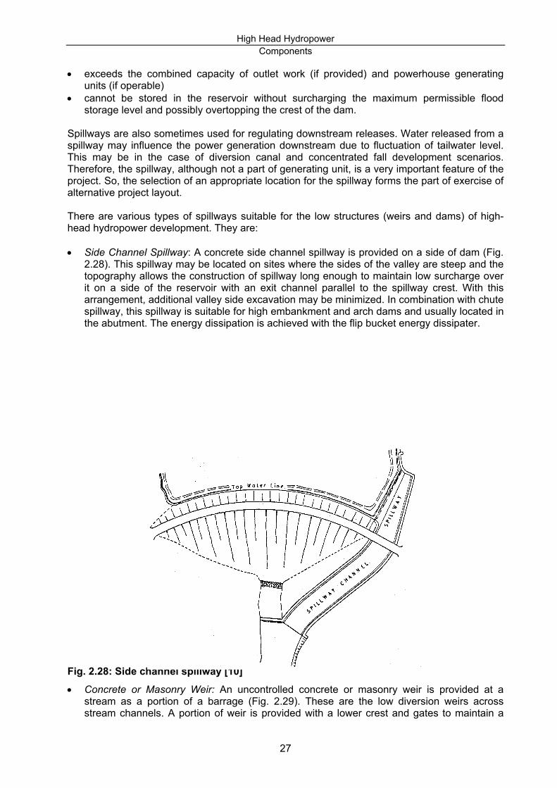
Spillways are also sometimes used for regulating downstream releases. Water released from a spillway may influence the power generation downstream due to fluctuation of tailwater level. This may be in the case of diversion canal and concentrated fall development scenarios. Therefore, the spillway, although not a part of generating unit, is a very important feature of the project. So, the selection of an appropriate location for the spillway forms the part of exercise of alternative project layout. There are various types of spillways suitable for the low structures (weirs and dams) of high-head hydropower development. They are: • Side Channel Spillway: A concrete side channel spillway is provided on a side of dam (Fig.
2.28). This spillway may be located on sites where the sides of the valley are steep and the topography allows the construction of spillway long enough to maintain low surcharge over it on a side of the reservoir with an exit channel parallel to the spillway crest. With this arrangement, additional valley side excavation may be minimized. In combination with chute spillway, this spillway is suitable for high embankment and arch dams and usually located in the abutment. The energy dissipation is achieved with the flip bucket energy dissipater.
Fig. 2.28: Side channel spillway [10] • Concrete or Masonry Weir: An uncontrolled concrete or masonry weir is provided at a
stream as a portion of a barrage (Fig. 2.29). These are the low diversion weirs across stream channels. A portion of weir is provided with a lower crest and gates to maintain a
27

High Head Hydropower Components
deep pond of water on one side of the stream where an Intake may be located. Excess water and debris can be spilled from this crest. In case of high flood, the sluice gate may be operated for passing the flood as well as the sediments deposited near the intake. This arrangement is suitable for concrete gravity or arch dams. The location of overflow spillway and the sluice is dictated by width of the dam crest and powerhouse location, if it is in the case of concentrated fall or diversion canal development. In case of arch dams, the overfall spillway is located at the center of the dam.
Fig. 2.29: Ungated diversion weir spillway • Morning Glory with tunnel: An uncontrolled morning glory with tunnel is suitable in narrow
valleys where space for wide-crest structures along the axis of the dam is limited (Fig. 2.30). It is especially suitable for the concrete gravity dams or arch dams. Energy dissipation is achieved with the provision of circular-invert deflector buckets. This type of spillway needs flow aeration arrangement.
28

High Head Hydropower Components
ay In arrangement of chute spillway, several alternatives should be considered such as the location of the spillway on the left or the right bank, or two symmetrical spillways on either side
Fig. 2.30: Morning Glory with tunnel spillway • Overflow spillway: This type of spillway, usually controlled by tainter gates, is used for
concrete gravity dams or arch dams. It is also useful as tunnel spillway and may be used as an alternative to this (Fig.2.31). They can be designed as free over flow or as overflow with spillway chute.
Fig. 2.31: Gated overflow spillway • Chute spillway: This type of spillway, as shown Fig. 2.32 is useful especially for the high
embankment dam because of its inherent readjustments of shape caused by time-related settlements [4].
Fig. 2.32: Chute spillw
of the bank. The conditions listed below should be considered in spillway layout work: • straight approach flow condition • minimum approach channel excavation depth • safe release of water into the river by aligning the chute in the direction of river channel and
making provision of energy dissipation.
29

High Head Hydropower Components
In some cases, the spillway may not be part of the dam structure and located somewhere else where topography and geology permits to do so (Fig. 2.33)
Fig. 2.33: Separately located spillway [10] Determination of preliminary size of the spillway is necessarily based on the high flood discharge (PMF) depending upon the size of the dam structure and safety requirement. The spillway size has to be adjusted to arrive at acceptable freeboard for the determination of crest level of the dam. These matters have been dealt in the chapter “engineering design”. Following are some important remarks on the arrangement of chute spillway. Although this already falls into design requirement, the information may be useful in the selection of proper chute alternatives. For details it is recommended to refer USBR, ASCE etc. Weir Control Structures: For controlled water release to downstream, spillways need some control structures. An ogee shaped weir with piers makes up the weir control structure. Ogee should be set adequately high above the approach channel floor to obtain optimum flow condition over the crest [10]. Depending upon the approach channel depth and the foundation requirement the ogee shape may vary. Piers: Piers are necessary to support the hydrostatic pressure on gates and piers themselves. This may also serve as bridge piers for service or roadway bridges. Depending on the selected chute width and configuration the piers may be arranged either parallel to the axis of the chute or radially inclined to it. If there are no constraints for the width of the chute, the straight alignment of piers is preferred. It is necessary to avoid the vortices which may be formed at the piers by gradually expanding the openings between piers. Stoplog slots: These are necessary to provide in the piers, usually upstream of the service gates to allow the maintenance of gates. Service Bridges are required to facilitate the operation and maintenance of the gate and also to provide an access to the gate hoists.
30

High Head Hydropower Components
basically four types of stilling basins according to the Froude number [11].
If chute spillways have more than one openings, it is better, for the maintenance purpose, to provide divide wall to contain the flow in separate channels. The chute floor, except the transition from ogee section to the chute, should be of uniform thickness throughout its length. Flip Buckets: These are the predominant type of energy dissipaters for the chute spillways, where stilling basins would not be economical to provide. It is described in the following section. Flow Aeration Provision: Flow aeration is an important aspect to save the spillways from the erosion due to cavitation, especially tunnel, shaft or chute spillways. This is achieved by making provision of air ramps and slots in the chute spillway floor. Provision of this may also reduce the cost of the spillway. 2.1.8 ENERGY DISSIPATERS The water in its natural states dissipates its energy throughout the way to sea. However, water retained behind the dam stores energy, which, when released down stream may cause serious problem of bed and bank erosion. Hence it is utmost important to provide energy dissipaters just below the spillway or within the spillway floor, if the geological condition downstream is not favourable. Following paragraph describes the various types of energy dissipaters which may be suitable for the one or other types of spillway described above. • Stilling basins with or without end sills and or baffle blocks: They are applicable for all low or
intermediate spillways which have relatively low head. For high velocity discharge, e.g., from chute spillway of high dam, stilling basins are extremely long and therefore not recommendable. The main principle of this basin is to still or reduce the velocity and the related energy of the flow by forming hydraulic jump within the short length of stilling basin as far as possible (Fig. 2.34). The USBR provides detailed description and design of
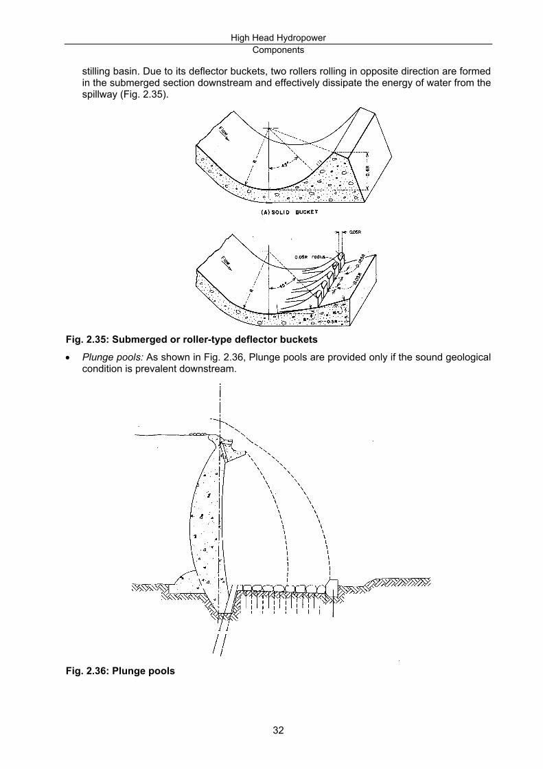
Fig. 2.34:Typical stilling basins. • Submerged or roller-type deflector buckets, solid or slotted: These are useful in combination
with overfall spillways of high gravity dams when the tailwater level is too high to develop a
31
High Head Hydropower Components
stilling basin. Due to its deflector buckets, two rollers rolling in opposite direction are formed in the submerged section downstream and effectively dissipate the energy of water from the spillway (Fig. 2.35).
Fig. 2.35: Submerged or roller-type deflector buckets • Plunge pools: As shown in Fig. 2.36, Plunge pools are provided only if the sound geological
condition is prevalent downstream.
Fig. 2.36: Plunge pools
32

High Head Hydropower Components
2.1.9 SEDIMENT HANDLING STRUCTURES 2.1.9.1 GENERAL For most of the reservoir/storage type projects the sediment handling structures such as sand trap, gravel traps are generally not provided. The capacity of reservoir is determined when taking into consideration the sediments inflow. On the other hand, a sediment trap with flushing structures is a must in the sediment laden mountainous rivers for the run-of-river (ROR) type or run-of-river (PROR) with small peaking. Depending upon topography, geology and quantity and characteristics of sediments, these structures may be located underground or on surface and may vary in size and shapes. Experiences show that the reservoir may fill up quickly after a few years of operation due to inaccuracy in estimation of sediment flow and the precipitation. For example: about 66 % of the dead storage (12 Mm3) of the 114 m rockfill type Kulekhani reservoir in Nepal was filled within 13 years of its operation after the abrupt cloud burst in 1993 [12]. The 148 m high and 2750 m long Tarbela Dam constructed in 1977 on Indus river in Pakistan had a reservoir live storage capacity of 11.5 km3. By 1991, siltation had reduced the live storage to 10.6 km3. Similarly, the 115 m high and 2560 m long Mangla dam constructed in 1967 in Pakistan had a reservoir live storage capacity of 6.6 km3. Due to siltation the capacity has been reduced to 6.4 km3 by 1988. Since the reservoir has silted up completely, except for a small headpond for daily storage, Warsak power plant of Pakistan constructed in 1960 is now running as a run-of- river plant. The siltation problem had caused serious wear on its rotating parts. The above mentioned examples suggest that a sediment handling structure (silt trapping and flushing arrangement) is extremely necessary to provide. Alternatively, some flexibility in the design and layout should be considered so that in the future any change in the structure could be possible. While dealing with the reservoir sedimentation, the location of the delta deposit is significant to locate the dam axis so that land upstream does not experience rising flood levels and the reservoir life is longer than the economic recovery time for the project. 2.1.9.2 SILL, BEDLOAD-DEFLECTING APRON AND SKIMMER The purpose of a sill is to retain the bedload. It should be used at the beginning of an inlet. A bedload-deflecting apron is also applied to deflect the bedload retained by the sill during the periodical flushing. Therefore, a flushing sluice always has to be located near the inlet. Similarly a skimmer prevents some of the floating debris from getting caught up in the trashrack. It should be inclined towards the spillway to encourage the stream gradually to sweep this debris downstream. The skimmer also prevents trashrack from floating ice (Fig. 2.37).
Fig. 2.37: Sill, bedload-deflecting apron and the skimmer
33
High Head Hydropower Components
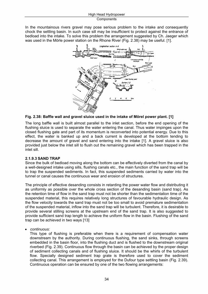
In the mountainous rivers gravel may pose serious problem to the intake and consequently chock the settling basin. In such case sill may be insufficient to protect against the entrance of bedload into the intake. To solve this problem the arrangement suggested by Ch. Jaeger which was used in the Mörle power station on the Rhone River (Fig. 2.38) may be useful. [1].
Fig. 2.38: Baffle wall and gravel sluice used in the intake of Mörel power plant. [1] The long baffle wall is built almost parallel to the inlet section, before the end opening of the flushing sluice is used to separate the water entering the canal. Thus water impinges upon the closed flushing gate and part of its momentum is reconverted into potential energy. Due to this effect, the water is banked up and a back current is developed at the bottom tending to decrease the amount of gravel and sand entering into the intake [1]. A gravel sluice is also provided just below the inlet sill to flush out the remaining gravel which has been trapped in the inlet sill. 2.1.9.3 SAND TRAP Since the bulk of bedload moving along the bottom can be effectively diverted from the canal by a well-designed intake using sills, flushing canals etc., the main function of the sand trap will be to trap the suspended sediments. In fact, this suspended sediments carried by water into the tunnel or canal causes the continuous wear and erosion of structures. The principle of effective desanding consists in retarding the power water flow and distributing it as uniformly as possible over the whole cross section of the desanding basin (sand trap). As the retention time of flow in the sand trap must not be shorter than the sedimentation time of the suspended material, this requires relatively long structures of favourable hydraulic design. As the flow velocity towards the sand trap must not be too small to avoid premature sedimentation of the suspended material, inflow into the sand trap will be turbulent. Therefore, it is desirable to provide several stilling screens at the upstream end of the sand trap. It is also suggested to provide sufficient sand trap length to achieve the uniform flow in the basin. Flushing of the sand trap can be achieved in two ways [13] • continuous:
This type of flushing is preferable when there is a requirement of compensation water downstream by the authority. During continuous flushing, the sand sinks, through screens embedded in the basin floor, into the flushing duct and is flushed to the downstream original riverbed (Fig. 2.39). Continuous flow through the basin can be achieved by the proper design of sediment collecting canals and of flushing sluice. It should be the whirls of the turbulent flow. Specially designed sediment trap grate is therefore used to cover the sediment collecting canal. This arrangement is employed for the Dufour type settling basin (Fig. 2.39). Continuous operation can be ensured by one of the two flowing arrangements:
34

High Head Hydropower Components
waste. This is also called an automatic settling basin.
Fig. 2.39: Sand trap with continuous flushing
a) Series of basins: In this arrangement some of the basins can be flushed while others are
operating. b) Permanent operation of basins: The continuous flushing of settled sediments can be
achieved by increasing the water demand by about 10 per cent. In this way sediments accumulating at the bottom can be flushed continuously by discharging the excess water to
• intermittent: In intermittent flushing major amounts of sand first settle in the basin and are then removed by a flushing process; either by manual or by automatic operation (Fig. 2.40).
35

High Head Hydropower Components
Fig. 2.40: Sand trap with intermittent flushing [13] 2.1.9.4 FLUSHING SLUICE Functionally, it is always better to locate a flushing sluice in between inlet structure and spillway. Structurally a flushing sluice located in the body of the dam is nothing but a barrage without sill. Its bottom level concedes with the bed level. A flushing sluice is also necessary to provide at the end of the settling basin to flush out the silt. This arrangement may be called bottom outlet which may be equipped with a flushing valve. Bottom outlet located in the dam body is primarily for the releasing compensation water downstream. This arrangement may also be incorporated with flushing of sediments in some cases. 2.1.9.5 BOTTOM OUTLETS In some dams bottom outlets are provided to release water during flood period. If designed properly, the bottom outlets are useful devices to flush the gravel accumulated behind the dam. 2.1.9.6 DIVERSION TUNNELS Diversion tunnels are primarily meant for diverting river during the construction period of dam. After construction these tunnels are usually plugged with concrete and have no further use. With some special design arrangement, these structures may be used for flushing sediments and compensation discharge downstream. 2.2 WATERWAYS 2.2.1 POWER CONDUIT SYSTEMS The power conduit systems of high head hydropower project consist of headrace conduit, surge bay/tank, pressure shaft or penstock and tailrace conduit. 2.2.1.1 POWER CONDUIT FOR FREE FLOW DEVELOPMENT • Power Canal
Power canals and free flow tunnels are used as power conduits for free flow development. Topographical and geological factors are the major aspects to be considered during the planning and implementation stages of a canal. On steep mountain sides the tracing of the canal should closely follow the contour lines of the terrain. Canals may be designed with cross-sections through cut, over fills and in cut-and-fills (Fig. 2.41).
Fig. 2.41: Cross-sections of earthen canals and concrete flumes [1].
36

High Head Hydropower Components
On the other hand, it may not always be possible to follow the irregular contour lines of rugged mountainous area. In such situation, the deep valleys are to be crossed with the help of aqueducts (such as elevated flumes, canal/pipe bridges) and high ridges by free flow tunnels as shown in Fig. 2.42.
Fig. 2.42: Location of a pipe bridge over rugged terrain [1] An access road along any canal should be provided so that points of incipient leakage or failure are readily accessible. The provision of a road will govern the top and bottom width in many cases. Adequate freeboard must be provided above the normal water surface to avoid the over topping of roads during flood. Similarly, suitable drainage should be provided to avoid the storm water running along the power canal [14]. In long canal it may be desirable to provide spillways at suitable places to prevent the over topping of the canal banks during abnormal floods. The alignment and cross-section of canal should be based on the reliable information on the geologic formation, the dip of layers, the quality of rock (degree of fissuring, permeability, strength, frost resistance, tendency to weathering, etc.). On sloping terrain embankments should be constructed with staggered foundations having horizontal contacting surfaces. The foundation should extend sufficiently deep through weathered soil and contact with sound rock. According to E. Mosonyi, the construction of open power canals may meet difficulties if
• the mountain slope is not stable, • the mountain slope is too steep, • the mountain slope above the canal is likely to produce much rubble, • snow avalanches are to be expected, or • in extremely severe and long winter periods the water freezes in the canal.
In the above mentioned conditions, the following solutions may be used [1]: Special design and/or remedial measures have to be adopted in such cases.
Covered canals are generally constructed in the canal alignment crossing settlements to provide protection against pollution and to meet safety requirements. • Headpond:
37
High Head Hydropower Components
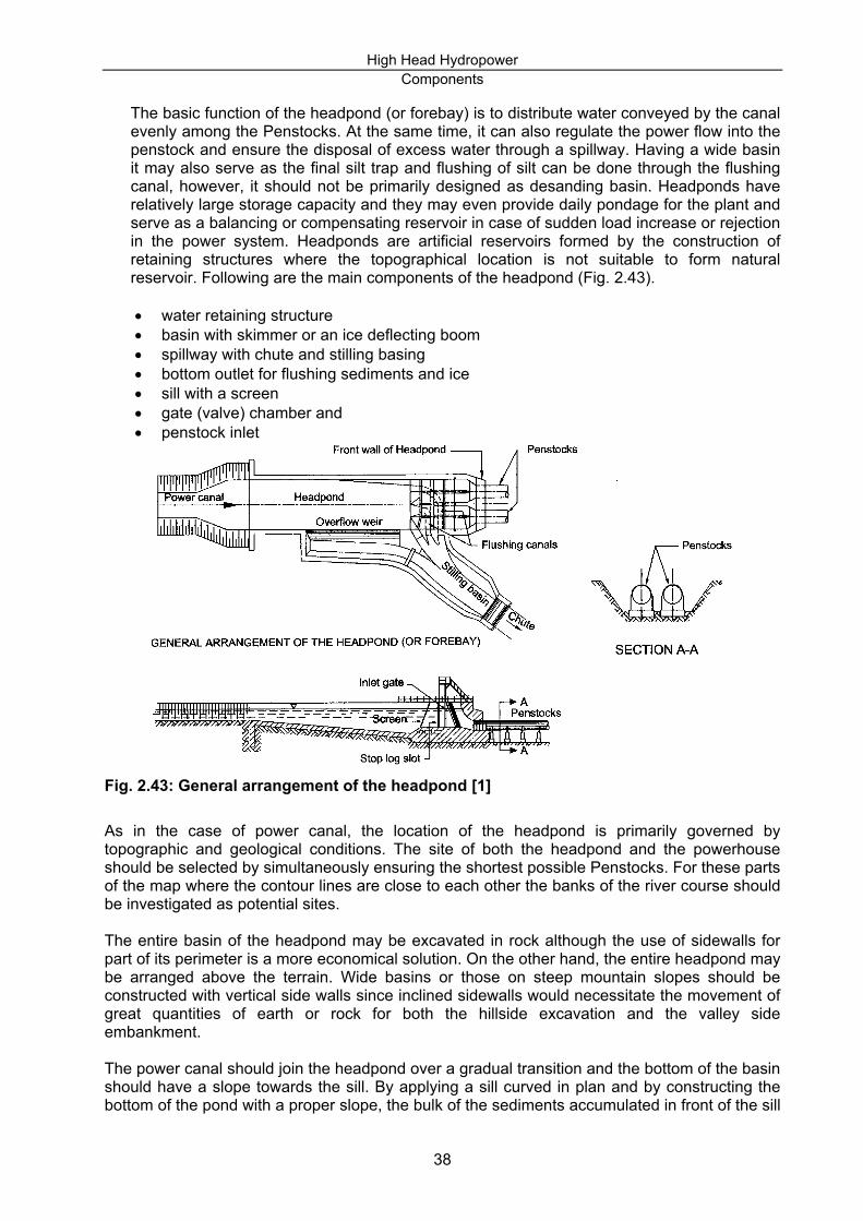
The basic function of the headpond (or forebay) is to distribute water conveyed by the canal evenly among the Penstocks. At the same time, it can also regulate the power flow into the penstock and ensure the disposal of excess water through a spillway. Having a wide basin it may also serve as the final silt trap and flushing of silt can be done through the flushing canal, however, it should not be primarily designed as desanding basin. Headponds have relatively large storage capacity and they may even provide daily pondage for the plant and serve as a balancing or compensating reservoir in case of sudden load increase or rejection in the power system. Headponds are artificial reservoirs formed by the construction of retaining structures where the topographical location is not suitable to form natural reservoir. Following are the main components of the headpond (Fig. 2.43). • water retaining structure • basin with skimmer or an ice deflecting boom • spillway with chute and stilling basing • bottom outlet for flushing sediments and ice • sill with a screen • gate (valve) chamber and • penstock inlet
Fig. 2.43: General arrangement of the headpond [1] As in the case of power canal, the location of the headpond is primarily governed by topographic and geological conditions. The site of both the headpond and the powerhouse should be selected by simultaneously ensuring the shortest possible Penstocks. For these parts of the map where the contour lines are close to each other the banks of the river course should be investigated as potential sites. The entire basin of the headpond may be excavated in rock although the use of sidewalls for part of its perimeter is a more economical solution. On the other hand, the entire headpond may be arranged above the terrain. Wide basins or those on steep mountain slopes should be constructed with vertical side walls since inclined sidewalls would necessitate the movement of great quantities of earth or rock for both the hillside excavation and the valley side embankment.
The power canal should join the headpond over a gradual transition and the bottom of the basin should have a slope towards the sill. By applying a sill curved in plan and by constructing the bottom of the pond with a proper slope, the bulk of the sediments accumulated in front of the sill
38

High Head Hydropower Components
penstock arrangements :
Fig. 2.44: Some examples of headpond and power inlet arrangements [1]
may be flushed with water under pressure through the bottom outlet. In the case of wide Headponds baffle piers are usually constructed at the inlet in order to ensure the even distribution of flow.
The spillway or wasteway is usually an ogee type weir located in the valley side, a retaining wall of the basin with a sufficient length to discharge the entire full-load water supply with a small increase in the basin level. If the spill discharge is small, it may be possible to combine it with the bottom outlet by applying suitable structural arrangements. In case the prevailing topography does not permit to place a long weir and the discharge to be handled is great then a siphon spillway may be provided. The wasteway and the bottom outlet should be connected immediately at the foot of the basin and the wastewater may be either diverted into a suitable riverbed in a near-by side valley, or conveyed by a special chute. The overfall spillway is automatic and without the control gate whereas the bottom outlet, in most cases, must be controlled by a vertical-lift gate. Sediments accumulating before the sill can also be flushed through the bottom outlet. If the flushing arrangement does not function properly and sediments remaining in the headpond are significant, this may be removed by mechanical means (dredging).
The inlet of penstock is to be protected from sediment intrusion by means of a sill, which is followed by the screen. Provision should be made for cleaning the screen. Flow to the pressure conduits is controlled by either vertical-lift or Tainter gates located in the gate chamber. An emergency closure of the stop-log type should also be provided. A gate house should be constructed to encompass all gate operating equipment. Gates are operated by electric remote control from the switch room of the powerhouse and also directly from the gate house. An automatic gate closing system should be installed in case of turbine runaway or penstock failure. An open air shaft or automatic air vent should always be provided behind the gate to prevent the occurrence of vacuum.
Following figures (Fig. 2.44) demonstrate some of the solutions for the headpond from sill to
2.2.1.2 POWER CONDUIT FOR DIVERSION TUNNEL DEVELOPMENT Power conduit for diversion tunnel type hydropower projects is generally a pressure tunnel. This paragraph is more devoted to the description of the pressure tunnel. However, it is to be noted
39

High Head Hydropower Components
that there are three other types of tunnels used in hydropower projects which are also briefly described here. • Free-flow tunnel: Free-flow tunnels are basically used in diversion canal type development,
because hydraulically the design of this type of tunnel is similar to open channel. Design of lining and stress analysis concerning the external forces to be resisted are similar to the principles established for conventional, so called; ‘dry tunnels’ such as: highway tunnel, railway tunnels and mining cuts [1]. However in contrast to ‘dry tunnels’ the water load in the free-flow tunnel may influence the designing and the selection of the type of lining (Fig. 2.45).
Fig. 2.45: Free-flow tunnel. • Service Tunnel: The design principles of service tunnels are also similar to ‘dry tunnels’.
They are used for the casing of steel pipeline or Penstocks connecting reservoir to powerhouse in high-head installation. In the service tunnels one or more Penstocks may be supported on cradles. Therefore, dimensions and shaping of their cross-section depend on the requirements about measures and placing of the pipes. Fig. 2.46 shows some examples of service tunnels.
Fig. 2.46: Service tunnels • Adit and access tunnels respectively are used for the close examination of rock formation
and provide access to the main tunnels ( viz., pressure tunnels, surge tank, underground powerhouse, etc.) for construction and maintenance purposes. The layout and sizing of these tunnels are also necessary to establish the appropriate alternatives for the hydropower project. The design of these tunnels also falls in the category of ‘dry tunnels’ and hence they are not dealt here.
• Pressure tunnels: According to E. Mosonyi, pressure tunnels may be classified as follows: a) low-pressure tunnel H< 5 m b) medium-pressure tunnel 5<H<100 m c) high-pressure tunnel H>100 m Where H is the head above the soffit of the tunnel (Fig. 2.47).
40

High Head Hydropower Components
Fig. 2.47: Head over the pressure tunnel To address the internal roughness of the tunnel, they are also classified into two types: a) unlined tunnel: excavated in good rock condition. b) lined tunnel with cement, steel or concrete materials; either for structural reason or for sealing purpose. Following aspects should be kept in mind while aligning the pressure tunnel: • As far as possible, the tunnel should be aligned in the shortest line on the topography.
The tunnel should be kept under an adequate top and lateral cover of sound rock. To achieve this, great care should be taken in the selection of portal site, which should, if possible, be at points where there is little overburden and where the ground is steeply sloping. Suitable portal or intake sites are to be found in small ravines and watercourses. However, a great care should be taken to select these sites because a watercourse, in taking the line of least resistance, may follow the line of a fault or other zone of natural weakness [15]. Geological fault should be avoided as far as possible. In doing so, it may be necessary for the tunnel to deviate from a straight line. It may also be possible to align the tunnel perpendicular to the fault.
• Gradient is another important aspect to be considered in tunneling. For free-flowing
tunnels the gradient will be controlled by the hydraulic considerations to drive the water by gravity. However, in pressure tunnels the hydraulic gradient is controlled by the upstream and downstream water level. Therefore, the geometric gradient does not play a significant role. For the sake to simplify drainage and promote economy in spoil handling, it is sometimes preferable to drive the tunnel uphill. It may be sometimes necessary to break the gradient to allow intermediate Adit from lower level, so that the Adit could be used as natural drainage.
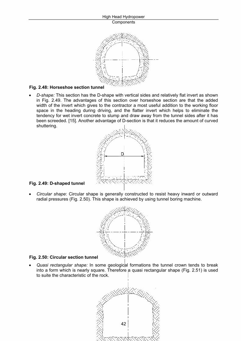
Shape of Tunnels: There are various cross-sections which have already been adopted for hydraulic tunnels. The selection of an appropriate cross-section depends partly upon the hydraulic conditions, partly on practical considerations, and partly on the nature of the rock through which the tunnel is to be driven. These cross-sections are as follows: • Horseshoe form (Fig. 2.48): This section has two advantages. Possessing an equivalent
circular section, in one hand, the calculation of discharges, friction losses, etc., is slightly simplified. On the other hand, it is strong in its resistance to external pressure.
41
High Head Hydropower Components
42
form which is nearly square. Therefore a quasi rectangular shape (Fig. 2.51) is used
Fig. 2.48: Horseshoe section tunnel • D-shape: This section has the D-shape with vertical sides and relatively flat invert as shown
in Fig. 2.49. The advantages of this section over horseshoe section are that the added width of the invert which gives to the contractor a most useful addition to the working floor space in the heading during driving, and the flatter invert which helps to eliminate the tendency for wet invert concrete to slump and draw away from the tunnel sides after it has been screeded. [15]. Another advantage of D-section is that it reduces the amount of curved shuttering.
Fig. 2.49: D-shaped tunnel • Circular shape: Circular shape is generally constructed to resist heavy inward or outward
radial pressures (Fig. 2.50). This shape is achieved by using tunnel boring machine.
Fig. 2.50: Circular section tunnel • Quasi rectangular shape: In some geological formations the tunnel crown tends to break
into a to suite the characteristic of the rock.

High Head Hydropower Components
Fig. 2.51: Quasi-rectangular section Like in headrace canal, in rugged mountainous area where irregular topographical contour lines are prevalent, it is sometimes necessary to align the tunnel over a rivulet or beneath it. In such cases the tunnel has to be joined with the pipe bridge or inverted siphon as shown in Fig. 2.52.
Fig. 2.52. Crossing of a river by pipe bridge [16] The following formulas derived by F. Fahlbush may be used to determine the preliminary dimensions of the tunnel [1]. However, it is suggested to optimize the diameter before preliminary cost estimation.
For concrete lined conditions (2.1) 48.062.0 QD =
For steel-lined conduits 12.0
45.0
12.1HQD = (2.2)
2.2.2 PENSTOCKS
43
Penstocks are the most important components of the waterway for the hydropower installation (Fig. 2.53). Unlike the penstock for the low-head hydropower installation, Penstocks for high-head hydropower installation bear much greater internal pressures and are always laid on and towards the slope. Therefore, great care should be paid to the geological conditions of the slope and the installation condition of the penstock. The layout of the penstock for high-head installation should be accomplished together with the layout of forebay or surge tank and the powerhouse.

High Head Hydropower Components
Fig. 2.53: A view of Penstock The alternative to such a pipeline is to arrange the tunnel at a low level so that it connects directly to the turbine. Whether a pipeline or a low-level tunnel is adopted is largely governed by the overall costs, and many factors have to be taken into consideration, e.g. the nature of the ground, whether composed of sound rock or deposited material; the amount of rock cover above the tunnel; the most desirable position for the portal with regard to the most suitable slope of the tunnel for construction, drainage, ventilation, access, and the variation in water pressures likely to occur in the system; the effect of the pipeline on the amenities of the district; and vulnerability to attack in wartime [9]. 2.2.2.1 LAYOUT OF THE PENSTOCKS There are mainly two layout schemes for the penstock [17]: 1. a separate layout, i.e. each unit has one penstock and 2. a common penstock with branching pipes at its lower end (manifolds) For high-head projects with relatively smaller discharges, several units are usually connected to a single penstock. Arguing on the selection of single penstock as most economical solution, E. Mosonyi suggests that the number of penstock should not be greater than one unless some manufacturing difficulties are justified [1]. Mathematically, E. Mosonyi has demonstrated that the amount of steel required for several penstocks may be significantly high as compared to the single penstock option [1]. According to his observation, the alternative based on identical head loss should be considered for the economic comparison. On the other hand, more than one penstock is desirable for the safety of operation. This leads to the optimization of the penstock number. As a rule of thumb, it is suggested to use a separate layout when plant head is less than 40-60 m and the discharge is high to supply large turbines. Due to the large discharge, the size of the penstock would be tremendously big. Therefore, in such case it is necessary to feed the turbine with separate Penstocks. Whereas, when the plant head is greater than 80 m, a common penstock with branching pipe is more feasible [17]. Penstocks are generally made of steel and used only in the case of unsuitable geological conditions of the powerhouse sites. In some cases, reinforced concrete or wooden Penstocks are also in use for high-head installation. For small installation plastic pipes are also in use. Description of which is given in the subsequent paragraphs. With respect to the location of the penstock and the method of support, two essentially different solutions may be observed [1]: Buried Penstocks which are supported continuously on the soil at the bottom of a trench backfilled after placing the pipe. The minimum thickness of the cover over the pipe should be about 1.0 to 1.2 meters.
44

High Head Hydropower Components
• Advantage: • Buried Penstocks are less vulnerable to the effect of temperature variations; • conveyed water is less affected from freezing; • support aesthetics of the surrounding; • protection against damage caused by violence; • owing to the continuity of support, it is structurally preferable.
• Disadvantages: • less accessible for inspection and therefore also difficult for the maintenance and
repair; • installation is expensive in case of large diameter or/and of rocky terrain; • tendency to slide in case of low frictional coefficient of the soil.
Exposed Penstocks which are installed above the surface of the terrain and supported on piers (supports or saddles). It has no continuous support.
• Advantages: • easy access for inspection and hence the maintenance and repair operations can be
carried out easily; • installation is less expensive in case of large diameter or/and of rocky terrain; • safety against sliding may be ensured by properly designed anchorage;
• Disadvantages:
• Full exposure to external variations in temperature; • conveyed water is prone to freeze in severe climatic condition; • owing to the spacing of supports and anchorage significant longitudinal stresses may
develop especially in pipes of large diameter designed for low internal pressures. Buried pipes are used only on mildly sloping terrain where the top layers do not consist of rock. While the exposed arrangement is more frequently used in steep terrain. To avoid the unfavourable geological condition of the site, in some cases the large-diameter pipes have been located in a service tunnel in spite of the considerable expenditure required for the construction of the latter. For this reason, partly buried and partly exposed type Penstocks are also in use [1]. The penstock in plan is generally aligned, as far as possible, straight. However, changes in direction are sometimes unavoidable. The profile of the penstock alignment on the terrain is shown in (Fig. 2.54)
45

High Head Hydropower Components
46
Fig. 2.54: Penstock profile [19] There are mainly two types of connection layouts for Penstocks with powerhouse: 1. Direct connection arrangements:
Fig. 2.55: Various solutions for the direct connection of the Penstocks to the powerhouse Direct connection arrangements (Fig. 2.55) are popular, now-a-days, due to the following advantages:
• no distributing pipe system is necessary • the end anchorage block may be arranged immediately in front of the power house and
consequently the rigidly fixed pipe section may be very short (Fig. 2.55) • lowest anchor block may be omitted entirely or united with the machine foundation of the
powerhouse substructure, if the latter alone is capable of resisting the thrust transmitted from the Penstocks
• exclusion of bends and bifurcation diminishes hydraulic losses. 2. Lateral penstock arrangements: To safe-guard the powerhouse against flooding in case of
occasional penstock bursts, one of the following lateral arrangements shown in Fig. 2.56 may be applied:

High Head Hydropower Components
47
Fig. 2.56: Lateral penstock arrangements Even though the direct connection is preferable regarding its various advantages, site conditions may decide in favour of the lateral arrangement. The method of connecting the penstock to the units is ultimately dictated by the condition whether it is possible to locate the powerhouse at right angles to the line of fall and thus to the horizontal projection of the penstock, or whether it is more expedient to set the powerhouse with its longitudinal axis parallel to the conduit. The former situation calls obviously for a direct connection, while the latter for a lateral arrangement
A direct solution preferred for the aforementioned structural as well as hydraulic considerations may prove impractical, if other conditions call for an arrangement parallel to the penstock. For example: the orientation of the machine hall may be governed by the availability of space required for the transformers and switchyard or the alignment of the tailwater tunnel to carry the wheel discharge away from the powerhouse may sometimes change the entire station layout. This calls for the careful studies of the topography, geology and other considerations.
It should also be noted that the selection of direct connection to the powerhouse does not contradict the principle to apply as few Penstocks as possible for economic reason (eventually one). By choosing high-capacity generating units the number of unit Penstocks can be reduced, and a favourable bifurcation can be obtained by direct connection as well (Fig. 2.57)

High Head Hydropower Components
Fig. 2.57: Unit Penstocks branching off at the lower end of the penstock 2.2.2.2 TYPES OF PENSTOCKS In selecting the type of penstock pipe for a specific site, the following factors should be considered [8]: • required operating pressure and diameter; • method of coupling; • weight and ease in handling and accessibility of site; • local availability of pipe; • maintenance requirements and expected life; • nature of terrain to be traversed and • effect on pipe of water quality, climate, soil, and possible tampering. The corresponding movements of the penstock pipes and the longitudinal stresses in the pipe due to temperature variations are the main aspects to be taken care of. To avoid these problems the rigid joints between pipe sections should in some places be substituted by elastic ones. According to the structural behavior of the conduit three different types of pipeline may be classified [1]: 1. Rigid type: The pipe sections may be rigidly connected to each other and to both uphill and
downhill structures, restricting the pipe movement completely. In such case, significant longitudinal stress may develop in the pipe. Rigid pipelines can be installed if no great changes in temperature are to be expected. Buried pipes may be constructed as rigid type.
2. Semi-rigid type: To prevent from the longitudinal movements the penstock is frequently
divided into relatively long tangents connected by expansion joints or flexible couplings. If several elbow sections permitting small movements are installed, long pipelines of relatively small diameter with rigid joints throughout may also be considered as semi rigid.
3. Loose-coupled type: Penstocks may be constructed with expansion joints between each
adjacent section either continuously supported or fixed at a single point. Due to the loose coupling, the longitudinal movements of each section are completely unrestricted and therefore, no axial forces may develop in such pipelines. Loose-coupled pipelines have usually smaller dimensions and are buried. Large diameter pipes operating under high pressures should never be of loose-coupled type.
According to the construction materials, the Penstocks may be classified as explained in the following paragraphs. 2.2.2.2.1 STEEL PENSTOCKS Steel Penstocks are widely used in all kinds of hydropower construction. A thorough description of steel pipes, their design and selection can be found in publications and manuals [Mosonyi, Inversin, Creager and Justin, Bonnyman, etc.]. Only few remarks on the steel Penstocks are given here for ready reference:
48

High Head Hydropower Components
49
• Seamless rolled or seamless drawn pipe: The length of rolled or drawn pipe sections generally does not exceed 6 to 8 meters. In exceptional case 12 m long sections have also been manufactured [1]. It is used for smaller diameters ranging from 300 mm up to 600 mm.
• Shop-welded or shop-riveted (d<3 m): Usually made of plate steel with longitudinal joints for
welding or riveting. Considering the transportability of the pipe, the maximum diameter of the pipe is 3 m. The length of individual penstock sections should not exceed the range of 4 to 8 m. The maximum weight should not exceed 25 tons for shipping purpose [1]. The ends of each section are prepared and shaped at the workshop according to the type of field joints, i.e. welded, riveted or flange-bolted. Because of the following advantages, the welded pipes are installed most frequently:
• lower weight • lower hydraulic resistance and • faster in-situ erection.
• Shop-welded or shop-riveted (d>3 m): Penstocks are also same as foregoing, but owing to limitations imposed by transport facilities usually delivered to the site as half or third cylinders
Riveted joints were used in the past. Welded joints are frequently used at the present time. However, the flanged joint is still required where a special piece or a device which may need reassembling is coupled to the penstock (e.g. valve). Flexible couplings to be used with pipelines are shown in Fig. 2.58.
Fig. 2.58: Flexible joint 2.2.2.2.2 OTHER TYPES OF STEEL PENSTOCKS • Banded Penstocks : Banding consists essentially of inducing pre-stress in the smooth pipe
of relatively thin wall by means of forged steel hoops. Consequently banded steel pipes are significantly pre-stressed, as a result of which high operating pressures can be carried by thin-walled pipes (Fig 2.59). Wire-rope banded or cable-hopped pressure pipes are applied mainly at covered or protected (service tunnel) installations.

High Head Hydropower Components
Fig. 2.59: Banded steel pipe 2.2.2.2.3 PROTECTION AGAINST CORROSION Steel Penstocks must be protected against corrosion. Steel pipe may be protected by applying protective coating inside and outside of the pipe in case of exposed pipe. Buried pipes may be protected on the outside by a layer of vibrated concrete or tarred layers of jute cloth, hot enameling, protective metal coats, etc. [1]. Formerly, zinc coating was used, but at present coating with an adhesive plastic layer is used. In some cases a modern procedure for cathodic and stray-current protection is also adopted. The rate and extent of corrosion is influenced by various factors as mentioned below: • the chemical composition of water • atmospheric effects • precipitation • electrolytic effects of stray currents • the composition of soil and groundwater 2.2.2.2.4 REINFORCED CONCRETE PENSTOCKS: With the considerable development in the design and manufacturing of the reinforced concrete pipes, they are permissible to be used in high pressure conduits of power stations. Penstocks of reinforced concrete are less expensive and can offer considerable savings in steel. Reinforced-concrete Penstocks may be either exposed or buried. Smaller pipes having diameter less than 1 m are always prefabricated, while the larger ones are sometimes cast in place. Two main types of prefabricated reinforced-concrete pressure pipes may be distinguished: 1. slack reinforcement and 2. pre-stressed pipes Reinforced-concrete pressure pipes may be constructed by manual compacting, spinning, and vibration. Pre-stressed reinforced concrete pipes are manufactured by tension wrapping a steel wire of high tensile strength on the outside of a conventional reinforced-concrete pipe (see detail in [1]). Prefabricated reinforced-concrete pipes are generally used for operating pressures of up to 5 to 15 kg/cm² although special pipes of this type have been manufactured for even higher loads [1]. Prefabricated pipes are usually manufactured with diameters between 300 and 3000 mm, and common lengths between 3 and 7 m. Wall thickness from 8 to 25 cm is common for prefabricated pressure pipes, whereas for pre-stressed pipes it sometimes reduces to 6 cm (4 cm core pipe + 2 cm protective coating). Because of lower heat conductivity of concrete, reinforced-concrete pressure pipes are superior to steel pipes as far as freezing is concerned. For low capacity power station also prefabricated asbestos cement pipes were used. They have high tensile capacity (up to 300 kg/cm²) and can be manufactured up to 12 m long without difficulty. They are light and can be easily installed at the site. However, the wide use of asbestos has been restricted in several countries due to environmental objections. Prefabricated pipe sections are placed on a bed of lean concrete. Cast-in-site reinforced-concrete pipes should, whenever possible, be buried to reduce variations in temperature. 2.2.2.2.5 POLYVINYL CHLORIDE (PVC) AND GLASSFIBRE-REINFORCED PLASTIC (GRP) PENSTOCKS
50

High Head Hydropower Components
High density PVC pipes used for water supply can also be used for Penstocks in small hydropower installation. They are light, easy to install by local skill and can be produced locally. However they should be buried in ditches or wrapped or coated to protect them from sunlight. High-strength glassfibre-reinforced plastic (polymer) pipes (GRP pipes) which were developed in 1960 are now widely applied in the small hydropower installations in Norway, Japan and Malaysia [17]. provides some comparison between two types of GRP pipes produced by Jutum group of manufacturer in Norway and Electric Power Development Co. Ltd in Japan. The Jutum type GRP pipes were specially developed for the use in other type of water engineering, but they may also be used for small hydropower installation with a head of up to 120 m. However, the Japanese GRP pipes were specially developed for small hydropower Penstocks. The unit cost of the GRP pipes produced in developed countries is less than that produced in developing countries. However, with the development of the polymer industry in developing countries, GRP pipes have future prospects in small hydropower development [17].
Table 2.1: Difference between two types of GRP pipes [17] Items Japanese
Pipes Jutum Group
Pipes Notes
Linear thermal expansion Coefficient (l/oC) Design pressure range (Mpa) Diameter range (mm) Ratio of hoop tensile strength to axial tensile strength Wall thickness (mm) Specific weight Maximum HD
1.1 x 10⁻⁶ 0.25-2.25 200-3000 2.2 12-60 2 200
30 x 10-5 0.25-1.6 400-2000 2-9 5-24 1.7-1.8 120
The smaller the better the higher. The better Japanese pipes are better for penstocks Japanese pipes have greater rigidity Japanese pipes are a little heavier
2.2.2.3 PRESSURE SHAFTS As alternative to the Penstocks, pressure conduits may be created vertical or inclined shafts excavated in the mountain and provided with a steel lining. This arrangement is applied only in the case of good rock conditions (high strength and free of fracturing). There is no essential difference from the structural point of view between slightly inclined pressure tunnel and the sharply inclined or even vertical pressure shafts. Therefore, the criteria for the selection of this type of pressure conduit are also similar to that of pressure tunnels. Pressure shafts are exceptionally used for underground powerhouse (see underground powerhouse layout). The evolution of various types of penstocks and steel-lined pressure shafts can be characterized by diverse extreme measures and combined parameters. From the table, it is evident that neither the head nor the diameter can alone characterize the capacity of the penstock/shaft. According to E. Mosonyi, two complex parameters are to be introduced (for detail see [1]): a) the bearing capacity of the pipe or strength parameter
51

High Head Hydropower Components
b) the power capacity or the capacity parameter
Table 2.2: High power Penstocks (source: Müller and Mussnig in [1])
Plant Country Year of
inauguration
Design pressure head H
(m)
Diameter at bottom
d (cm)
Hoopforce at bottom
Hd/10 (kg/cm)
Discharge Q
(m3/sec)
Penstock type
Reisseck Salanfe Huinco Roseland Malta Mauvoisin Mont-cenis Collegio Kaunertal Mantaro Lamoux Kemano Cubatao Cimego Kurobe Murray I
Austria Switzerland Peru France Austria Switzerland France Columbia Austria Peru France Canada Brazil Italy Japan Australia
1956 1950 1963 1959 1974 1954 1967 1965 1963 1985 1960 1954 1953 1955 1959 1964
1960 1620 1420 1380 1350 1110 1020 1080 985 975 880 870 845 820 680 580
95 110 210 300 260 150 300 190 285 260 190 330 320 280 300 343
18,600 17,800 29,800 41,400 35,100 16,700 30,600 20,500 28,100 25,400 16,700 28,700 27,000 23,400 20,400 19,900
4.5 7.0 25.0 50.0 42.0 13.5 51.0 20.0 48.0 33.0 13.0 62.0 72.0 34.0 54.0 74.0
B ET S S S E ET E S E E S S E ET E
Notations : E=exposed, ET=exposed in service tunnel, B=buried, S=steel lining in shaft 2.2.2.4 SIZING PENSTOCK PIPES When sizing a penstock pipe, two parameters must be specified: • its diameter, which should be selected to reduce frictional and therefore energy losses within
the penstock to a acceptable level, and • the thickness of its walls, which should be selected to accommodate the pressures
encountered during plant operation. For determining the economic diameter the graph proposed by G. Gerrand as shown in Fig.2.60 may be used for the preliminary sizing.
52

High Head Hydropower Components
Fig. 2.60: The mean value of economical penstock diameter plotted against discharge and head. This graph provides information as to the mean diameter. After the penstock diameter has been determined, some larger and smaller diameters are assumed. Then, estimation of their hydraulic loss and the cost of pipes for each diameter are computed. Finally, the alternatives with the incremental cost versus the increased energy revenue will be compared and an optimal economic pipe is selected. There are also several formulas prescribed by various authors to calculate the approximate size of economic diameter of the Penstocks ( [1], [17], etc.). 2.2.3 SURGE TANK Any hydroelectric station is sensitive to load variation. In hydroelectric projects, especially in high-head installations, where the water is diverted from the intake and brought to the turbine by a long pressure conduit, a considerable inertia effect due to the movement of mass of water column is observed [1]. Due to this inertia a high pressure is developed in the conduit system during rapid opening and closing of the valve and guide-vane of the turbine. This effect is called water hammer effect which can be regulated with the help of pressure release valves effectively on closure of turbine guide-vane. However, they cannot assist in accelerating the water column on increase of load, i.e. on opening of the guide-vane [18]. In such situations, a surge tank or a surge chamber is generally provided at the suitable location to avail the water hammer effect by shortening the length between reservoir and the machines. 2.2.3.1 TYPES OF SURGE TANK 2.2.3.1.1 ACCORDING TO THE HYDRAULIC DESIGN: Different types of surge tanks are shown in Fig. 2.61:
53

High Head Hydropower Components
nstream surge tank [6]
Fig. 2.61: Different types of surge tanks • Simple surge tanks consist of a vertical standpipe as shaft or as basin connected to the
penstock with an opening large enough so that there is no appreciable loss in head as the water enters the surge tank. These type of tanks are hydraulically unstable [19]. They may be sometimes provided with over-fall.
• Chamber surge tanks: Surge tanks with expansion chambers with or without over-fall
• Restricted orifice surge tank: This type of tank does not supply or accept excess penstock flow due to restricted opening between the tank and the penstock. However, this is hydraulically more stable
• Differential surge tank: This is a combination of a simple tank and a restricted-orifice tank. The inner tank responds with a minimum of head loss while the outer tank offers resistance to rapid flow into the tank.
2.2.3.1.2 ACCORDING TO THEIR LOCATION RELATIVE TO THE POWERHOUSE: • Upstream surge tank: This surge tank is located near the junction point of a long headrace
tunnel and the penstock (Fig. 2.62)
Fig. 2.62: Upstream surge tank [6] • Downstream surge tank: This is located immediately downstream of draft tube to prevent the
damage of turbine with the water hammer effect in the long tailrace tunnel (Fig.2.63). The application of a downstream surge chamber is justified by the following reasons [1]: • to prevent the separation of the water column in the draft tube, and/or in the tailwater
tunnel, in the case of rapid closure. • to prevent excessive pressures in the draft tube, and/or in the tailwater tunnel, in the case
of rapid opening.
Fig. 2.63: Dow2.2.3.1.3 ACCORDING TO THEIR LOCATION RELATIVE TO THE TERRAIN
54

High Head Hydropower Components
Fig. 2.66: Air-cushion surge chamber
• Recessed (fully or partially excavated in the earth) Type (Fig. 2.64):
Fig. 2.64: Recessed type surge tank [1] • Free-standing (exposed) Type (Fig. 2.65):
Fig. 2.65. Free-standing type surge tank [1] Finally, the above mentioned types of surge tanks are collectively called open-air or atmospheric surge tank/shaft [1]. Moreover air-cushion surge chambers are also in use in the high head installations. The air-cushion is achieved in a cavern-type chamber where the atmosphere is completely sealed off and an adequate high pressure below the roof of the chamber is created and maintained.
The structural arrangements of the foregoing surge tanks have been dealt in detail by E. Mosonyi [1]. Therefore, it has not been repeated here. In the following paragraphs we mainly deal with the advantages and function of surge tank.
55

High Head Hydropower Components
2.2.3.2 LOCATION CRITERIA AND FUNCTION OF SURGE TANKS To avoid the undue problem of water hammer effect in the pressure conduit, the uncontrolled pressure conduit between turbine and the first reservoir should not exceed approximately five times the head [18]. Other authors suggest to take three times the head [19]. If the topography does not allow to provide a short uncontrolled pressure conduit, a surge chamber is introduced in between the reservoir and the turbine. An introduction of surge tanks has the following four advantages [1]: • it intercepts and radically reduces the pressure surges due to water hammer and exempts
thereby the pressure tunnel form excessive internal loads, • by interrupting the closed system of the penstock and the pressure tunnel the surge tank
reduces the water hammer pressure upon the penstock, • the surge tank serves the improvement of regulation in various ways:
• firstly, it provides higher degree of stability to the system by reducing the water hammer pressure fluctuations because the response of the turbine governor is in proportion to the pressure variation.
• secondly, by diminishing the distance between the turbine and the next free water surface the speed control can be substantially improved which is a very important objective with plants participating in network frequency control.
• thirdly, for achieving governing stability, the conduit acceleration time has to be limited. To limit this time long waterways have to be interrupted by a free surface, i.e., by a surge tank. (refer [1] for detailed mathematical treatment)
• the surge tank provides water supply to the turbines in the case of starting up. Due to the fact that the acceleration of water mass in almost horizontal pressure tunnel is significantly low, the flow around the elbow would become discontinuous if no surge tank is introduced.
Provision of surge tank is a costly item. However, even if synchronous bypass relief valve is installed as an alternative means of protection against excessive water hammer, it will protect only in the case of sudden load rejection. Moreover, the penstock may be dimensioned to resist over pressure, but it would be uneconomical to design very long tunnel for over pressure. Therefore, in such case, the incorporation of surge tank is necessary. To avoid the negative pressure built at the elbow, the pressure conduit should always be located below the lowest possible hydraulic gradient throughout its entire length that could result from surge and water hammer as shown in Fig. 2.67.
Fig. 2.67: Ruling hydraulic gradient [6]
56

High Head Hydropower Components
While locating the surge tank in the pressure conduit system it is always desirable to reduce the pipeline length and thus to reduce the pressure variation. The arrangement of the pressure conduit should be discussed at the earliest possible moment with the turbine designers, particularly if site conditions make it difficult to restrict the unregulated length. 2.3 POWERHOUSE 2.3.1 POWERHOUSE TYPES The function of the powerhouse is to support and house the generating unit and its accessories as well as the water passage through the powerhouse. The purpose of the powerhouse is to provide good operating performance of the plants, cost saving and easy inspection and maintenance. Although powerhouse is an important component of hydropower scheme having its own independent characteristics its general arrangement should be in correspondence to the layout of the Penstocks and other components of waterways as well as to the setting of the mechanical equipment. In the foregoing chapter we have briefly discussed the arrangement of powerhouse relative to the Penstocks. In this chapter, we will investigate the various possible methods of introducing the pipelines into the powerhouse as well as types of powerhouses with advantages and disadvantages and also the general methods for sizing the powerhouses. A very comprehensive survey on general arrangements and dimensioning of the powerhouse is given by Keefe (1984), Mosonyi (1991) etc. Additional information can also be obtained from literature ([19]; [17]; etc.) The layout of the entire powerhouse is fundamentally based on the type of turbine and its shaft arrangement envisaged for the units. According to the mechanical equipment used, high-head powerhouses may be classified into following four groups [1]: 1. horizontal-shaft Francis turbines, 2. horizontal-shaft Pelton wheels, 3. vertical-shaft Francis turbines, 4. vertical-shaft Pelton wheels. According to the location of the whole powerhouse unit on the topography, they are: 1. surface or external type 2. semi-surface or slope type 3. underground type
57

High Head Hydropower Components
1. Turbine 4. Generator 2 Valve 5. Pump 3. Bifurcation 6. Coupling
Fig. 2.68: Types of powerhouse with respect to turbines 2.3.2 ARRANGEMENT OF RUNNERS The horizontal-shaft Francis turbines are very popular in small and mini hydropower installation [17] because of (1) less excavation; (2) simple substructure ; (3) smaller height of the powerhouse; (4) use of a conical draft tube; (5) easy inspection; (6) ease of installing fly-wheels to improve speed regulation; (7) easy for installation. However, this layout for higher capacity installation (large Francis turbine) is now very rare because of the following reasons: • horizontal-shaft machines require higher settings to reduce the cost of sealing the
generators and auxiliary electrical equipment against water • the floor space occupied by horizontal-shaft units is in general greater than for the vertical-
shaft setting. On the other hand horizontal shaft arrangement is adopted in most cases for Pelton wheels for the following two reasons: • the use of multiple-runner units • hydraulic conditions are not less favourable than with vertical-shaft machines. However, Pelton wheels supplied with more than two jets are preferably installed with a vertical shaft to minimize the space for machine hall. The level of the shafts is fixed in order to keep the wheel buckets above maximum tailwater level; machine hall floor level is therefore indirectly related to maximum tailwater level. This principal is same for both horizontal and vertical-shaft Pelton turbines with open- air or underground arrangements. In most cases, the powerhouses incorporating horizontal-shaft turbines are spliced vertically into two sections: 1. draft tube or tailrace chamber section (substructure) 2. turbine, generator and machine hall section (superstructure). Examples of developments featuring horizontal-shaft Francis turbines and Pelton turbines are illustrated in Fig. 2.69 and Fig. 2.70 respectively.
58

High Head Hydropower Components
Fig. 2.69: Example of Francis turbine with horizontal shaft [27]
59

High Head Hydropower Components
Fig. 2.70: Example of Pelton turbine with horizontal shaft [19] The obvious advantages of vertical-shaft settings against horizontal shaft settings once made them popular to be used in large hydropower installations. In these settings the powerhouse may be divided vertically into three sections: 1. draft tubes and the tailwater gallery section 2. penstock extensions and the turbine section 3. generator and machine hall section The first two sections are located in the substructure of the powerhouse whereas the third section is located in the superstructure. Sometimes the generator and machine hall are separately located in different halls. In this case the powerhouse is then resolved into four sections. A vertical cross-section of most frequently used arrangement of different powerhouses equipped with vertical-shaft Francis turbines is shown in Fig. 2.71.
Fig. 2.71: Example of frequently used vertical-shaft Francis turbine arrangement [19] Besides the generator, the machine hall may accommodate the turbine governor and the exciters, the valve control mechanisms. The machine hall may also accommodate the assembly bay to facilitate the assembly, maintenance and repair works on turbine and auxiliary equipment. In all cases the load from the superstructure must be transferred to the concrete substructure using suitable columns and girders combination. The columns and girders are usually of reinforced concrete or of steel profiles embedded in concrete, although steel structures have also been used on some occasions [1]. Proper architectural planning of the interior of powerhouse has to be done to accommodate the facilities such as control room, office rooms, cable distributor, shops, storage to provide pleasant working environment as well as the possibilities to accommodate the switching yard which also forms the part of the powerhouse. The exterior architecture of the powerhouse should be planned in such a way that it blends with the natural surrounding. Typical surface type installations with vertical-shaft Pelton wheels are shown in the Fig. 2.72. In this case also the type, general arrangement, size and number of the generating aggregates (turbines, generators, valves and their accessories) determine the main dimensions of the powerhouse. Its width is relatively large when indoor or semi-outdoor accommodation of any
60

High Head Hydropower Components
other installations are envisaged. Moreover, the space required for the Pelton wheels to accommodate necessary distributor nozzles and valves is generally large as compared to the same capacity of Francis type installation [1]. The setting of vertical-shaft Pelton turbine depends upon the maximum elevation of tailwater level. Consequently the vertical division of the powerhouse also depends on it.
Fig. 2.72: Example of frequently used vertical-shaft Pelton turbine arrangement [20] 2.3.3 UNDERGROUND POWERHOUSE 2.3.3.1 GENERAL As defined by E. Mosonyi, underground stations are those arrangements where the generating aggregates with their appurtenances are accommodated in underground caverns. A detail survey on the characteristics of underground powerhouse is given by Mosony 1991, Jaeger, 1970 etc. In favourable geological and topographical conditions an underground powerhouse render three significant advantages: • it is more economical • it ensures a higher safety against misfortunes and violence • it has negligible impact on landscape and environment. There are mainly four types of underground powerhouses developed so far [1]; [20]: 1. Swedish type characterized by a short pressure shaft and a long tailrace tunnel. In such
case, a downstream surge chamber is provided at the inlet to the tailrace tunnel. This type of arrangement is also called upstream station arrangement. This arrangement is used when the continuously rolling terrain does not enfavour for aligning horizontal pressure tunnel. Moreover, on the sloping terrain the internal pressure in a tunnel due to water hammer would be excessive. Therefore the main advantage of this arrangement is that the headrace exposed to high internal pressure is short, whereas the tailrace is negligibly affected by the
61

High Head Hydropower Components
d) Diagonal tunnel alignment with air-cushion surge tank (Norwegian solution)
internal pressure which can also be reduced by using the surge chamber. On the other hand, the cross-section of the tailrace tunnel would be larger than the pressure shaft. Therefore, on the basis of an economic analysis, it may turn out that the advantages do not outweigh the drawbacks. The head utilized in this arrangement varies generally between 25 and 50 m and may be used in medium head developments.
a) Upstream station arrangement (Swedish type) b) Downstream station arrangement (Swiss type) c) Intermediate location of the station (Italian arrangement)
Fig. 2.73: Characteristic types of underground developments 2. Alpine type (Fig. 2.73b) characterized by a long, almost horizontal pressure tunnel conveying
water close to the point of emergence to the surface, from where a steep pressure shaft continues down to the powerhouse. The tailrace is usually very short. This arrangement is also known as downstream station arrangement. At the junction of the pressure shaft and
62

High Head Hydropower Components
the tunnel a surge tank is usually provided. An underground valve chamber is also provided with proper access. Extremely high heads, exceeding several hundred or even one thousand meters, can be utilized in downstream station type developments by taking advantage of topographical conditions encountered in high mountains.
3. Fig. 2.73(c) shows schematically an intermediate arrangement to cope with the special topographical conditions of the site. This arrangement is characterized by the long headrace and tailrace tunnels. It is obvious that in this case upstream and downstream surge tanks are necessary to be provided.
4. Fig. 2.73(d) shows the essential features of arrangements where, instead of an open-air surge tank/shaft, an air-cushion surge chamber operates under considerable over-pressure. If the geological conditions permit, the shortest and, consequently, most economical tunnel profile can be chosen, i.e. the intake can straight diagonally be connected with the underground powerhouse. The primary condition for this arrangement is that thick rock layers of sufficient strength and impermeability are available in the vicinity of the powerhouse site. Since the overburden above a diagonal profile is very high, under favourable geological conditions, the pressure tunnel can remain unlined, which may be an enormous economic advantage in comparison with other viable alternatives.
Important economic advantages of underground arrangements are : 1. shortest pressure shaft and tailrace tunnel 2. saving in steel by avoiding lining 3. smaller surge tank dimensions due to reduced momentum of the water surface pendulation 4. overall costs of the conduit system are less with increase in the tailrace tunnel 5. reduced thickness of the penstock steel due to short length which tend to result in lower over
pressure due to water hammer effect 6. uninterrupted construction work even under severest winter conditions 7. property to be acquired for underground projects is significantly less. 8. smaller head losses 9. regular maintenance and repair costs are lower 10.periodical or even irregular maintenance and repair is also lower Important economic disadvantages are: 1. increased construction costs of the powerhouse 2. considerable costs of access tunnels 3. the need of separate gallery for the inlet valves 4. the need of special ventilation and air-conditioning 5. tailrace tunnel may require a more elaborate solution 6. higher cost of air-cushion surge chamber or downstream surge tank wherever necessary 7. additional need of transformer and switchgear cavern 8. cost of lighting and ventilation 9. cost of water drainage 10.running cost of air compressor in case of air-cushion surge chamber Considering the other obvious advantages (e.g., conservation of original landscape; air defense, etc.) of underground structures as compared to the surface type powerhouses, it can be concluded that under unfavourable natural conditions the underground powerhouse is the viable option. 2.3.3.2 ARRANGEMENT OF UNDERGROUND POWERHOUSES One important feature of an underground powerhouse (Fig. 2.74) is the smaller width of the machine hall as compared with the surface type. The experience proved that, in most cases, it is more expedient to save in the width of the power cavern than in its height. This requirement gives preference to application of vertical-shaft generating sets. As in surface location, both Pelton and Francis turbines may be employed. The minimum length of the powerhouse is
63
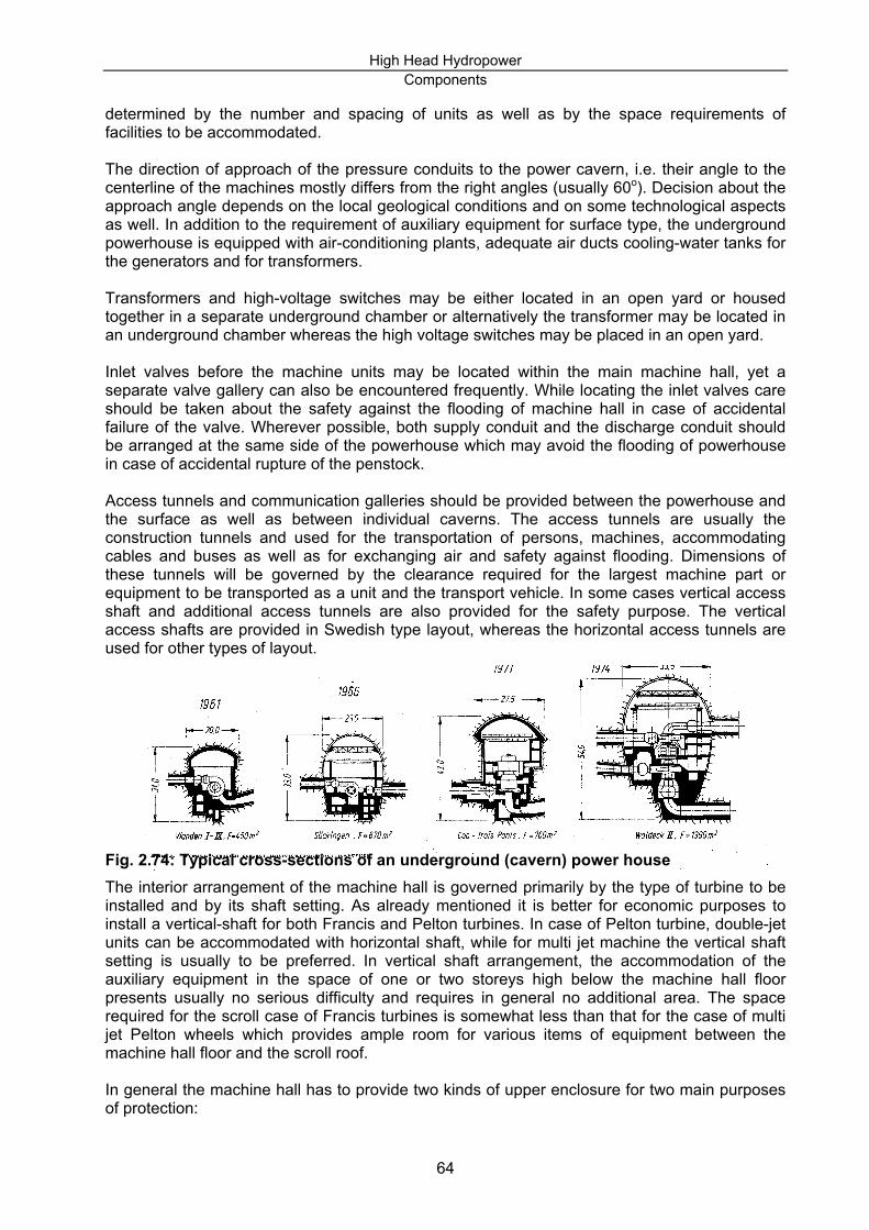
High Head Hydropower Components
determined by the number and spacing of units as well as by the space requirements of facilities to be accommodated. The direction of approach of the pressure conduits to the power cavern, i.e. their angle to the centerline of the machines mostly differs from the right angles (usually 60o). Decision about the approach angle depends on the local geological conditions and on some technological aspects as well. In addition to the requirement of auxiliary equipment for surface type, the underground powerhouse is equipped with air-conditioning plants, adequate air ducts cooling-water tanks for the generators and for transformers. Transformers and high-voltage switches may be either located in an open yard or housed together in a separate underground chamber or alternatively the transformer may be located in an underground chamber whereas the high voltage switches may be placed in an open yard. Inlet valves before the machine units may be located within the main machine hall, yet a separate valve gallery can also be encountered frequently. While locating the inlet valves care should be taken about the safety against the flooding of machine hall in case of accidental failure of the valve. Wherever possible, both supply conduit and the discharge conduit should be arranged at the same side of the powerhouse which may avoid the flooding of powerhouse in case of accidental rupture of the penstock. Access tunnels and communication galleries should be provided between the powerhouse and the surface as well as between individual caverns. The access tunnels are usually the construction tunnels and used for the transportation of persons, machines, accommodating cables and buses as well as for exchanging air and safety against flooding. Dimensions of these tunnels will be governed by the clearance required for the largest machine part or equipment to be transported as a unit and the transport vehicle. In some cases vertical access shaft and additional access tunnels are also provided for the safety purpose. The vertical access shafts are provided in Swedish type layout, whereas the horizontal access tunnels are used for other types of layout.
Fig. 2.74: Typical cross-sections of an underground (cavern) power house The interior arrangement of the machine hall is governed primarily by the type of turbine to be installed and by its shaft setting. As already mentioned it is better for economic purposes to install a vertical-shaft for both Francis and Pelton turbines. In case of Pelton turbine, double-jet units can be accommodated with horizontal shaft, while for multi jet machine the vertical shaft setting is usually to be preferred. In vertical shaft arrangement, the accommodation of the auxiliary equipment in the space of one or two storeys high below the machine hall floor presents usually no serious difficulty and requires in general no additional area. The space required for the scroll case of Francis turbines is somewhat less than that for the case of multi jet Pelton wheels which provides ample room for various items of equipment between the machine hall floor and the scroll roof. In general the machine hall has to provide two kinds of upper enclosure for two main purposes of protection:
64

High Head Hydropower Components
a) The supporting vault is constructed to protect the powerhouse against geological pressure
and to retain large pieces of loose rock. b) The inner roof (false ceiling) is to protect mechanical equipment in the machine hall and
primarily the generators against moisture dripping from the roof. Similarly, side walls are also an important factor to be considered in the design of underground powerhouse. In favourable geological condition, these walls may be left bare. Sometimes it may be required to reinforce them by bolting, shotcreting or supporting by concrete wall. A second layer of wall called ‘inner curtain’ wall is also necessary to be provided, however it has no structural importance. The main purpose of construction of inner walls is to create an air gap between the rock walls and the machine hall, protecting the layer from percolating moisture. Seepage and its drainage arrangement is also one of the most important aspects of the underground powerhouse. Water infiltrating through the rock wall or the exterior concrete wall, or dripping from the lower surface of the roof should be collected by gutters in the passage between the inner and exterior wall, and discharged by means of a drainage gallery into the tailrace. The necessary arrangements for bypassing water are also an important feature in the planning of hydropower installation. Need for bypass facilities will depend on the arrangement and requirements for releasing water differently as through the turbines. Separate sluices or channels or, in case of underground installation, tunnels that operate independently of the penstock may be required. Bypass is especially important to construct in case of cascade development which provide the desilting water to downstream powerhouse. Handling of the large components of hydroplants, including the turbine runner, the shaft of the unit, and the rotor and stator of the generator, requires large cranes to maneuver the equipment during installation and to remove components or entire assemblies for maintenance. However, the height of the machine hall should be as low as possible to reduce the cost. To achieve this special cranes are selected (Fig 2.75)
Fig. 2.75: Necessary height of the machine hall Tailwater pits for Pelton wheels, cross-flow, turgo etc. and draft tubes for Francis or Kaplan turbines are provided and duly lined to protect them from the high erosive velocity of water. Provision should be made for the downstream closure of the tailwater pit or top the draft tube of every individual unit. The downstream closure may be effected by a gate, or by stop logs controlled either from within the machine hall or from a separate gate gallery. With the downstream closure in position, the complete denaturing of the tailwater pit or of draft tube may be accomplished by a pump located in an adequately deep sump. Detailed explanation of the above mentioned arrangement with different examples can be found in [1]. 2.3.3.3 POWERHOUSE SUBSTRUCTURE AND TAILRACE TUNNEL The layout of powerhouse substructures depends greatly on the method adopted for removing the wheel discharge from the powerhouse. E. Mosonyi [1] distinguishes three main alternative arrangements for removing the wheel discharge: 1. Elbow type draft tubes connected to the Francis or Kaplan turbines (Fig. 2.76 a)
65

High Head Hydropower Components
2. Separate tailwater pits and culverts are provided for each unit. The culverts discharge outside the powerhouse into a common tailwater tunnel or covered tailrace (Fig.2.76 b). This is applicable for Pelton or cross-flow type turbines.
3. Tailwater gallery extending below the machine hall floor (Fig. 2.76 c). This arrangement is used in case of smaller discharges.
Fig. 2.76: Conveyance of water discharging from the wheels. In the case of tailwater tunnel developments handling great discharges excessive cross-sectional areas would be necessary for the tunnel. Therefore, the draft tubes, respectively tailwater culverts, of individual units are nowadays not united into a single tunnel. In such case the plant discharge is divided, for economic reasons, between two or more, tailwater tunnels. In selecting the alignment for a long tailrace canal or tailwater tunnel, the same hydraulic, topographic, geologic, settlement, traffic and other conditions should be taken into consideration as in case of the headrace, respectively pressure tunnel. In order to reduce the excavation volume, the tailrace at high-head plants may be designed for considerably higher flow velocities than those at low- head developments. As already mentioned, the tailwater tunnel may be designed from the hydraulic point of view according to one of the following three alternatives: • free-flow conditions • closed-conduit conditions • the tailwater tunnel discharges against counter pressure during flood periods only. The free-flow tunnel option requires large cross-sections. Therefore it is not economical unless the tail water tunnel is short. Moreover, if the level fluctuation of tailwater is very high it is not advisable to use free-flow option for economic reason. The closed-conduit option is better with respect to high amplitude of stage fluctuations in the recipient. It may require a surge chamber in this case. The choice of the free flow or close conduit regime also depends on the type of turbine to be installed. A free surface must be maintained under all operating conditions in the tailwater pit of Pelton wheels, and these pits are mostly connected to free-flow tunnels. However, in certain
66

High Head Hydropower Components
circumstances, the tailwater pit of Pelton wheel is kept as free flow by suppressing the water level in the initial gallery with a duct which discharges under pressure into the recipient.
67

High Head Hydropower Components
TABLE OF CONTENTS
1. High Head Hydropower Developments ............................................................................1 2. Civil Components..............................................................................................................3
2.1 Headwork And Appurtenant Structures .....................................................................3 2.1.1 Headwork ...........................................................................................................3 2.1.2 Headwork For Diversion Canal Development ....................................................4
2.1.2.1 General .......................................................................................................4 2.1.2.2 Structures....................................................................................................4 2.1.2.3 Construction Materials ................................................................................6
2.1.3 Headwork for Diversion Tunnel Development ....................................................6 2.1.3.1 General .......................................................................................................6 2.1.3.2 Low Pressure Tunnel ..................................................................................7 2.1.3.3 Consideration Of Geological Fault And Seismisity......................................7 2.1.3.4 Structures....................................................................................................7 2.1.3.5 Constructional Materials..............................................................................7
2.1.4 Headwork For Concentrated Fall Type Development ........................................7 2.1.4.1 General .......................................................................................................7 2.1.4.2 Dams...........................................................................................................7
2.1.5 Reservoir ..........................................................................................................14 2.1.5.1 General .....................................................................................................14 2.1.5.2 Elements Of Reservoir ..............................................................................15 2.1.5.3 Storage Capacity.......................................................................................16 2.1.5.4 Reservoir Yield..........................................................................................17
2.1.6 Power Intake ....................................................................................................17 2.1.6.1 General .....................................................................................................17 2.1.6.2 Intake For Diversion Canal Type Development.........................................18
2.1.6.2.1 Lateral Intake.........................................................................................18 2.1.6.2.2 Vertical Diversion Type Intake...............................................................21
2.1.6.3 Intake For Diversion Tunnel And Concentrated Fall Development ...........22 2.1.6.3.1 General..................................................................................................22 2.1.6.3.2 Forms Of Intake For Diversion Tunnell..................................................22
2.1.6.4 Sizing Of Intake Structure .........................................................................25 2.1.6.5 Intake Equipment ......................................................................................25
2.1.6.5.1 Intake Trash Screens ............................................................................25 2.1.6.5.2 Intake Trash Rakes ...............................................................................26
2.1.7 Spillway ............................................................................................................26 2.1.8 Energy Dissipaters ...........................................................................................31 2.1.9 Sediment Handling Structures..........................................................................33
2.1.9.1 General .....................................................................................................33 2.1.9.2 Sill, Bedload-Deflecting Apron And Skimmer............................................33 2.1.9.3 Sand Trap .................................................................................................34 2.1.9.4 Flushing Sluice..........................................................................................36 2.1.9.5 Bottom Outlets ..........................................................................................36 2.1.9.6 Diversion Tunnels .....................................................................................36
2.2 Waterways...............................................................................................................36 2.2.1 Power Conduit Systems ...................................................................................36
2.2.1.1 Power Conduit For Free Flow Development .............................................36 2.2.1.2 Power Conduit For Diversion Tunnel Development ..................................39
2.2.2 Penstocks.........................................................................................................43 2.2.2.1 Layout of the Penstocks............................................................................44 2.2.2.2 Types Of Penstocks ..................................................................................48
2.2.2.2.1 Steel Penstocks.....................................................................................48 2.2.2.2.2 Other Types Of Steel Penstocks ...........................................................49 2.2.2.2.3 Protection Against Corrosion.................................................................50
I

High Head Hydropower Components
2.2.2.2.4 Reinforced Concrete Penstocks: ...........................................................50 2.2.2.2.5 Polyvinyl Chloride (PVC) And Glassfibre-Reinforced Plastic (GRP) Penstocks 50
2.2.2.3 Pressure Shafts.........................................................................................51 2.2.2.4 Sizing Penstock Pipes...............................................................................52
2.2.3 Surge Tank.......................................................................................................53 2.2.3.1 Types Of Surge Tank ................................................................................53
2.2.3.1.1 According To The Hydraulic Design: .....................................................53 2.2.3.1.2 According To Their Location Relative To The Powerhouse: .................54 2.2.3.1.3 According To Their Location Relative To The Terrain...........................54
2.2.3.2 Location Criteria And Function Of Surge Tanks........................................56 2.3 Powerhouse.............................................................................................................57
2.3.1 Powerhouse Types...........................................................................................57 2.3.2 Arrangement Of Runners .................................................................................58 2.3.3 Underground Powerhouse ...............................................................................61
2.3.3.1 General .....................................................................................................61 2.3.3.2 Arrangement Of Underground Powerhouses............................................63 2.3.3.3 Powerhouse Substructure And Tailrace Tunnel........................................65
II

High Head Hydropower Components
LIST OF FIGURES
Fig. 1.1: High head diversion canal development [1] ...............................................................1 Fig. 1.2: Pressure tunnel development [1] ...............................................................................2 Fig. 1.3: Concentrated fall development [19] ...........................................................................3 Fig. 2.1: Fixed crest gravity weir ..............................................................................................5 Fig. 2.2: Gravity weir with movable crest [19] ..........................................................................5 Fig. 2.3: Tyrolean weir .............................................................................................................6 Fig. 2.4: Concrete Gravity Dam and its layout .........................................................................8 Fig. 2.5: Curved concrete gravity dam .....................................................................................9 Fig. 2.6: Arch Dam, Cross - Section ......................................................................................10 Fig. 2.7: Arch Dam, Plan........................................................................................................10 Fig. 2.8: Buttress Dam [19] ....................................................................................................11 Fig. 2.9: Various types of Buttress dams ...............................................................................11 Fig. 2.10: Rockfill Dam with impervious face upstream and with central core .......................12 Fig. 2.11: Types of homogenous-fill dams .............................................................................13 Fig. 2.12: Various forms of zoned-fill dams............................................................................13 Fig. 2.13: Dams with partial cut-off ........................................................................................14 Fig. 2.14: Elements of reservoir .............................................................................................15 Fig. 2.15: Area-Elevation curve..............................................................................................16 Fig. 2.16: Typical layouts for intake (after R. Müller in [1]).....................................................19 Fig. 2.17: Natural features along the stream (after Inversin) .................................................20 Fig. 2.18: Sitting a hydropower scheme between two consecutive irrigation intakes (after
Infersin)...........................................................................................................................21 Fig. 2.19: General layout of a vertical-diversion type intake (After H. Drobir in [1]) [20] .......22 Fig. 2.20: Ganeu Alpe Tyrolean weir, Austria [21] .................................................................22 Fig. 2.21: Tyrolean weir in Austria [22] ..................................................................................22 Fig. 2.22: Shaft headwork of a pressure tunnel development [1]...........................................23 Fig. 2.23: Intake of a pressure tunnel development without shaft..........................................24 Fig. 2.24: The fan-type intake of the Warsak dam-station project. ........................................24 Fig. 2.25: Intake tower ...........................................................................................................24 Fig. 2.26: Intakes from several reservoirs and brooks [19] ....................................................25 Fig. 2.27: Mechanically operated trash rakes. [24] ................................................................26 Fig. 2.28: Side channel spillway [10]......................................................................................27 Fig. 2.29: Ungated diversion weir spillway.............................................................................28 Fig. 2.30: Morning Glory with tunnel spillway.........................................................................29 Fig. 2.31: Gated overflow spillway .........................................................................................29 Fig. 2.32: Chute spillway........................................................................................................29 Fig. 2.33: Separately located spillway [10].............................................................................30 Fig. 2.34:Typical stilling basins. .............................................................................................31 Fig. 2.35: Submerged or roller-type deflector buckets ...........................................................32 Fig. 2.36: Plunge pools ..........................................................................................................32 Fig. 2.37: Sill, bedload-deflecting apron and the skimmer .....................................................33 Fig. 2.38: Baffle wall and gravel sluice used in the intake of Mörel power plant. [1]..............34 Fig. 2.39: Sand trap with continuous flushing ........................................................................35 Fig. 2.40: Sand trap with intermittent flushing [13].................................................................36 Fig. 2.41: Cross-sections of earthen canals and concrete flumes [1]. ...................................36 Fig. 2.42: Location of a pipe bridge over rugged terrain [1] ...................................................37 Fig. 2.43: General arrangement of the headpond [1].............................................................38 Fig. 2.44: Some examples of headpond and power inlet arrangements [1]...........................39 Fig. 2.45: Free-flow tunnel. ....................................................................................................40 Fig. 2.46: Service tunnels ......................................................................................................40 Fig. 2.47: Head over the pressure tunnel...............................................................................41 Fig. 2.48: Horseshoe section tunnel ......................................................................................42 Fig. 2.49: D-shaped tunnel.....................................................................................................42
III
High Head Hydropower Components
Fig. 2.50: Circular section tunnel ...........................................................................................42 Fig. 2.51: Quasi-rectangular section ......................................................................................43 Fig. 2.52. Crossing of a river by pipe bridge [16] ...................................................................43 Fig. 2.53: A view of Penstock.................................................................................................44 Fig. 2.54: Penstock profile [19] ..............................................................................................46 Fig. 2.55: Various solution for the direct connection of the Penstocks to the powerhouse....46 Fig. 2.56: Lateral penstock arrangements .............................................................................47 Fig. 2.57: Unit Penstocks branching off at the lower end of the penstock .............................48 Fig. 2.58: Flexible joint ...........................................................................................................49 Fig. 2.59: Banded steel pipe ..................................................................................................50 Fig. 2.60: The mean value of economical penstock diameter plotted against discharge and
head.......................................................................................................................53 Fig. 2.61: Different types of surge tanks ...............................................................................54 Fig. 2.62: Upstream surge tank [6].........................................................................................54 Fig. 2.63: Downstream surge tank [6] ....................................................................................54 Fig. 2.64: Recessed type surge tank [1] ................................................................................55 Fig. 2.65. Free-standing type surge tank [1] ..........................................................................55 Fig. 2.66: Air-cushion surge chamber ....................................................................................55 Fig. 2.67: Ruling hydraulic gradient [6] ..................................................................................56 Fig. 2.68: Type of powerhouse with respect to turbines ........................................................58 Fig. 2.69: Example of Francis turbine with horizontal shaft [27] ...........................................59 Fig. 2.70: Example of Pelton turbine with horizontal shaft [19] ..............................................60 Fig. 2.71: Example of frequently used vertical-shaft Francis turbine arrangement [19].........60 Fig. 2.72: Example of frequently used vertical-shaft Pelton turbine arrangement [20] ..........61 Fig. 2.73: Characteristic types of underground developments...............................................62 Fig. 2.74: Typical cross-sections of an underground (cavern) power house .........................64 Fig. 2.75: Necessary height of the machine hall ....................................................................65 Fig. 2.76: Conveyance of water discharging from the wheels. ..............................................66
IV

High Head Hydropower Components
TABLE OF TABLES
Table 2.1: Difference between two types of GRP pipes [17] .................................................51 Table 2.2: High power Penstocks (source: Müller and Mussnig in [1]) ..................................52
V


![Workshop Hydropower and Fish.pptx [Schreibgeschützt] - Workshop Hydropower and Fish... · Workshop Hydropower and Fish Existing hydropower facilities: ... spawning grounds and shelter](https://img.dokumen.tips/doc/110x75/5a8733247f8b9afc5d8da3c5/workshop-hydropower-and-fishpptx-schreibgeschtzt-workshop-hydropower-and-fishworkshop.jpg)