Embed Size (px)
Citation preview

Go to ‚View‘ menu and click on ‚Slide Master‘ to update this footer. Include DM reference, version number and date 1
Meteosat Third Generation (MTG): Lightning Imager and its products
Jochen Grandell
2
Topics
• Putting Meteosat Third Generation (MTG) into context
• Lightning monitoring from space – how does the concept work
• MTG Lightning Imager • Design and characteristics
• User products
• Proxy data development
• Summary
3
Who am I...
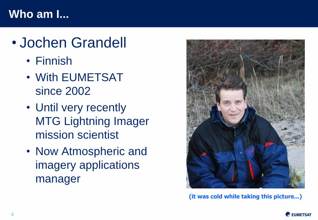
• Jochen Grandell • Finnish
• With EUMETSAT
since 2002
• Until very recently
MTG Lightning Imager
mission scientist
• Now Atmospheric and
imagery applications
manager
(it was cold while taking this picture...)

4
Where am I...
EUMETSAT headquarters in Darmstadt, Germany

5
Where I would like to be...

6
Topics
• Putting Meteosat Third Generation (MTG) into context
• Lightning monitoring from space – how does the concept work
• MTG Lightning Imager • Design and characteristics
• User products
• Proxy data development
• Summary

7
MSG MOP/MTP
Observation mission:
- MVIRI: 3 channels
Spinning satellite
Class 800 kg
Observation missions:
- SEVIRI: 12 channels
- GERB
Spinning satellite
Class 2-ton
1977 2019 and 2021 2002
(*) Ultraviolet Visible Near-infrared spectrometer
(UVN-S4) via GMES Sentinel 4
MTG to Secure Continuity and Evolution of EUMETSAT
Services
MOP/MTP MSG
MTG-I and MTG-S
Observation missions:
- Flex.Comb. Imager: 16 channels
- Infra-Red Sounder
- Lightning Imager
- UVN (*)
3-axis stabilised satellites
(two-satellite configuration)
Slide: 7

8
Topics
• Putting Meteosat Third Generation (MTG) into context
• Lightning monitoring from space – how does the concept work
• MTG Lightning Imager • Design and characteristics
• User products
• Proxy data development
• Summary

9
Lightning Detection from Space – from LEO to GEO
Optical Transient Detector (OTD) 1995-2000
Lightning Imaging Sensor (LIS) 1997-present
Feasibility of lightning detection from space by optical sensors has been proven by NASA instruments since 1995 on low earth orbits (LEO)
Results from LIS/OTD: Global lightning distribution
Annual flash density

10
The LI on MTG measures Total Lightning: Cloud-to-Cloud Lightning (IC) and Cloud-to-Ground Lightning (CG)
Geostationary lightning imaging – objectives and
benefits
Main objectives are to detect, monitor, track and extrapolate in time:
• Development of active convective areas and storm lifecycle
• Lightning climatology
• Chemistry (NOx production)
Main benefit from GEO observations:
homogeneous and continuous observations delivering
information on location and strength of lightning flashes to
the users with a timeliness of 30 seconds

11
Slide: 11
Detection of a Lightning Optical Signal
• Lightning with a background signal (bright clouds) changing with time:
• Lightning is not recognized by its bright radiance alone, but by its
transient short pulse character (also against a bright background)
• Variable adapting threshold has to be used for each pixel which takes
into account the change in the background radiance
Lightning signal
Background
Time
Radiation Energy at 777.4 nm
Night Day
12
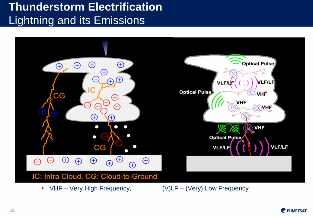
Thunderstorm Electrification
Lightning and its Emissions
• VHF – Very High Frequency, (V)LF – (Very) Low Frequency
13
Topics
• Putting Meteosat Third Generation (MTG) into context
• Lightning monitoring from space – how does the concept work
• MTG Lightning Imager • Design and characteristics
• User products
• Proxy data development
• Summary
14
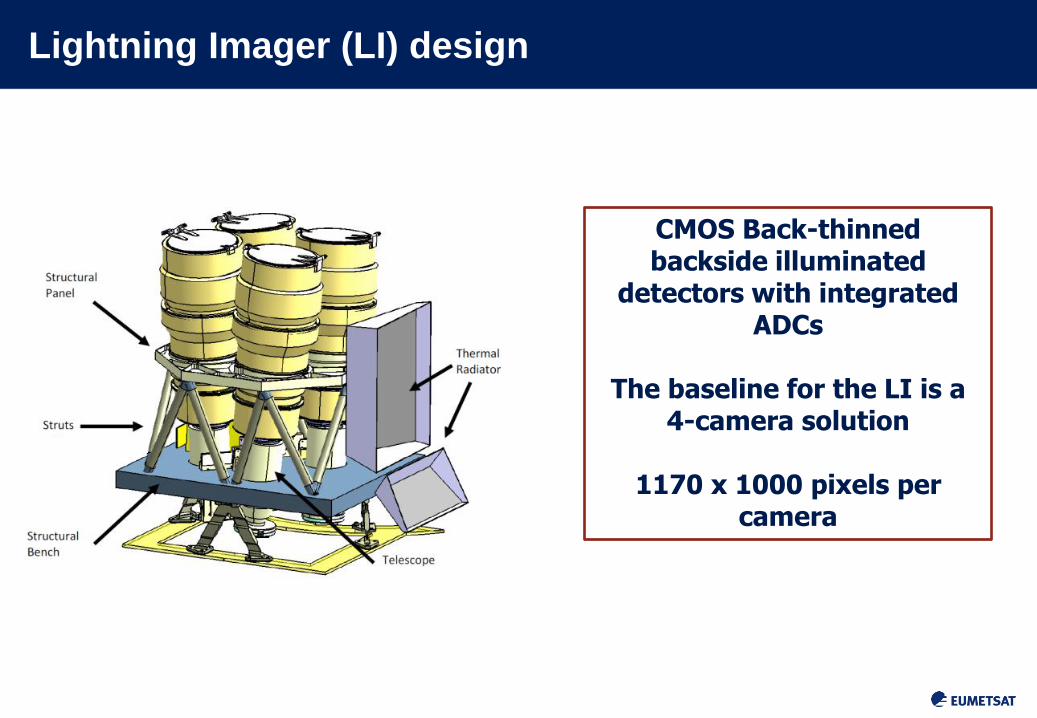
Lightning Imager (LI) design
Slide: 14
CMOS Back-thinned backside illuminated
detectors with integrated ADCs
The baseline for the LI is a
4-camera solution
1170 x 1000 pixels per camera

15
Lightning Imager (LI) – Main Characteristics
• LI main characteristics:
• Measurements at 777.4 nm
• Coverage close to visible disc
• Continuous measurements of (lightning) triggered events
• Ground sample distance at sub-satellite point ~4.5 km
• Integration time per frame 1 ms
• Background subtraction and event detection in on-board
electronics
Slide: 15
16
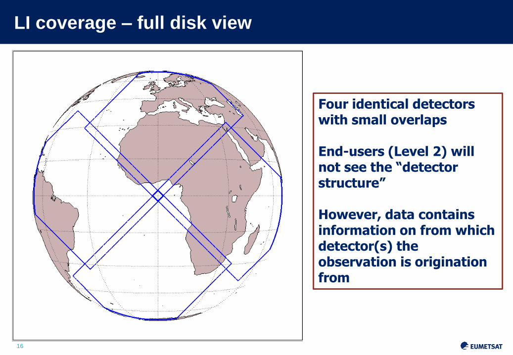
LI coverage – full disk view
Four identical detectors with small overlaps End-users (Level 2) will not see the “detector structure” However, data contains information on from which detector(s) the observation is origination from

17
LI coverage – another projection

18
Topics
• Putting Meteosat Third Generation (MTG) into context
• Lightning monitoring from space – how does the concept work
• MTG Lightning Imager • Design and characteristics
• User products
• Proxy data development
• Summary

19
Product terminology same as for LIS/GLM
• Events: what the instrument measures, a
triggered pixel in the detector grid
• Groups: collection of neighbouring triggered
events in the same integration period
(1 ms), representing a lightning stroke in
nature
• Flashes: a collection of groups in temporal and
spatial vicinity (XX km, YY milliseconds),
representing a “geophysical” flash.
20
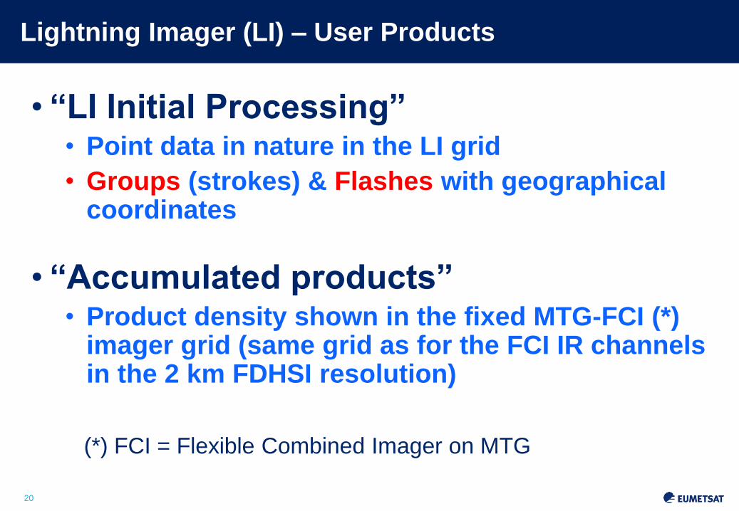
Lightning Imager (LI) – User Products
• “LI Initial Processing” • Point data in nature in the LI grid
• Groups (strokes) & Flashes with geographical coordinates
• “Accumulated products” • Product density shown in the fixed MTG-FCI (*)
imager grid (same grid as for the FCI IR channels in the 2 km FDHSI resolution)
(*) FCI = Flexible Combined Imager on MTG
Slide: 20
21
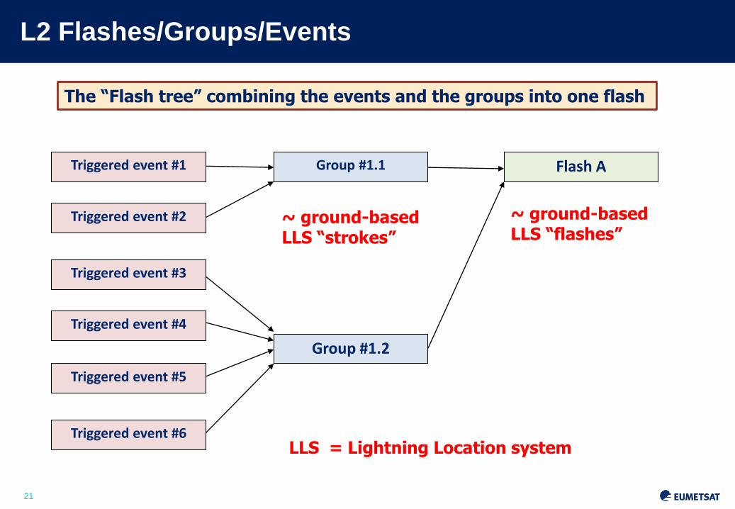
L2 Flashes/Groups/Events
Triggered event #1
Triggered event #2
Triggered event #3
Triggered event #4
Triggered event #5
Triggered event #6
Group #1.1
Group #1.2
Flash A
The “Flash tree” combining the events and the groups into one flash
~ ground-based LLS “strokes”
~ ground-based LLS “flashes”
LLS = Lightning Location system
22
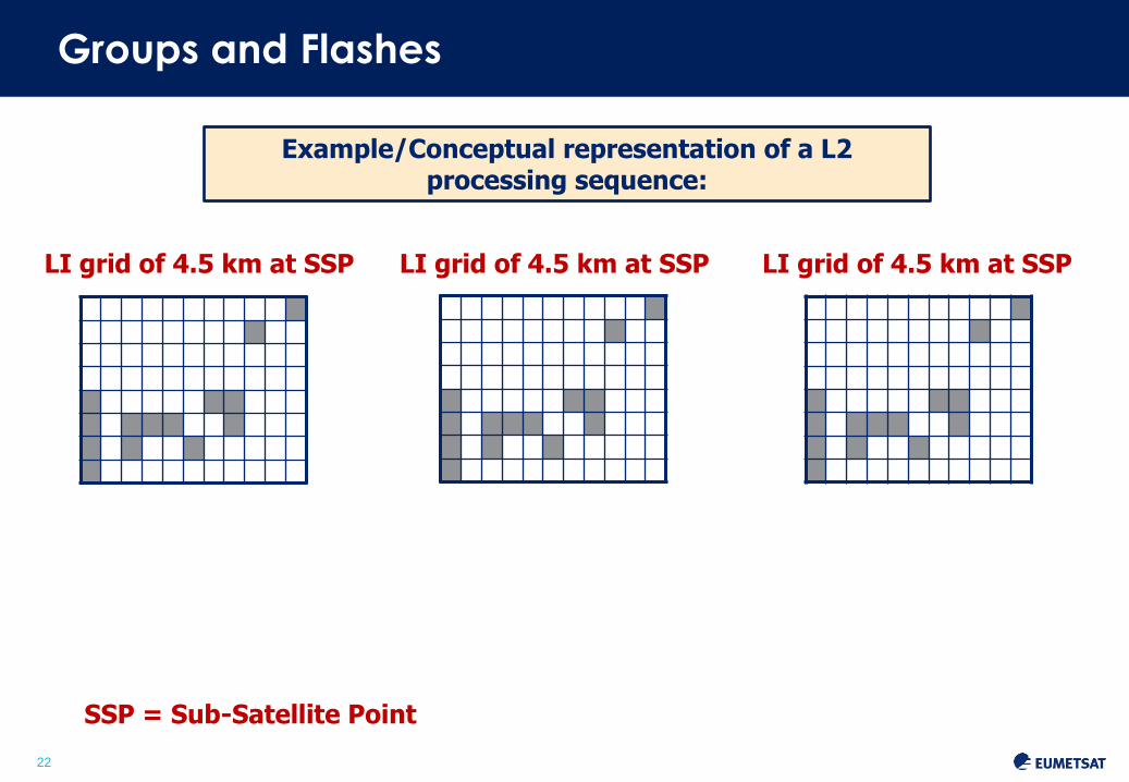
Example/Conceptual representation of a L2 processing sequence:
Groups and Flashes
LI grid of 4.5 km at SSP LI grid of 4.5 km at SSP LI grid of 4.5 km at SSP
SSP = Sub-Satellite Point
23
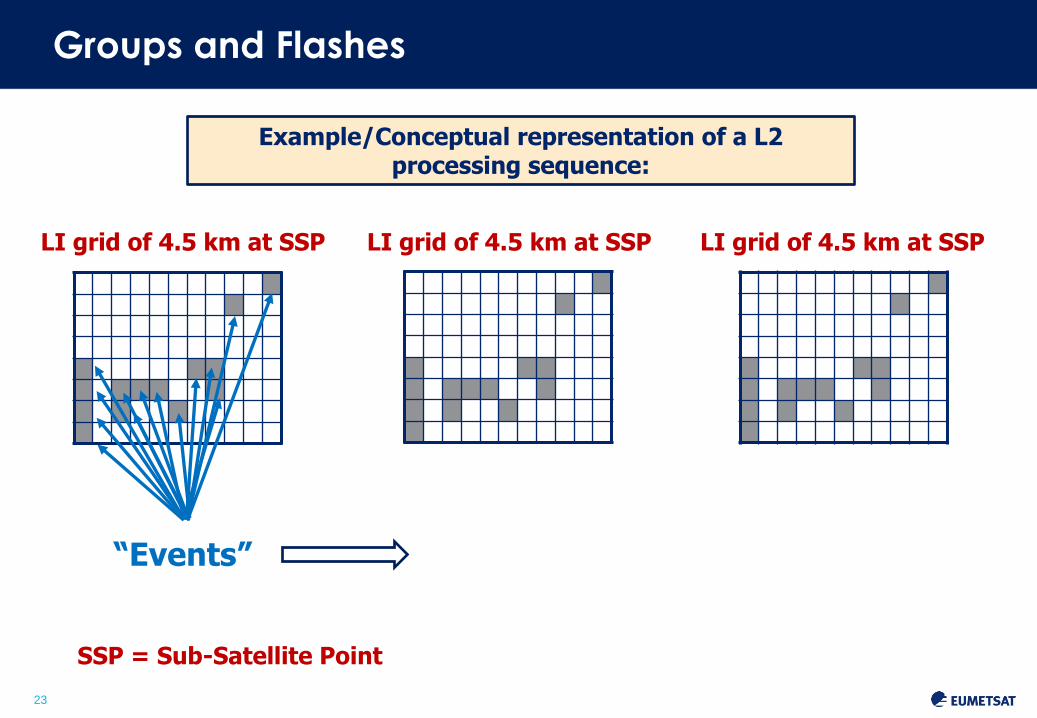
Example/Conceptual representation of a L2 processing sequence:
Groups and Flashes
“Events”
LI grid of 4.5 km at SSP LI grid of 4.5 km at SSP LI grid of 4.5 km at SSP
SSP = Sub-Satellite Point

24
Example/Conceptual representation of a L2 processing sequence:
“Groups”
Groups and Flashes
“Events”
LI grid of 4.5 km at SSP LI grid of 4.5 km at SSP LI grid of 4.5 km at SSP
SSP = Sub-Satellite Point

25
Example/Conceptual representation of a L2 processing sequence:
“Flashes” “Groups”
Groups and Flashes
“Events”
LI grid of 4.5 km at SSP LI grid of 4.5 km at SSP LI grid of 4.5 km at SSP
SSP = Sub-Satellite Point
26
L2 Accumulated Products
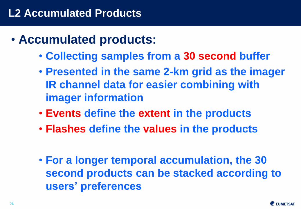
• Accumulated products:
• Collecting samples from a 30 second buffer
• Presented in the same 2-km grid as the imager
IR channel data for easier combining with
imager information
• Events define the extent in the products
• Flashes define the values in the products
• For a longer temporal accumulation, the 30
second products can be stacked according to
users’ preferences Slide: 26

27
Background to accumulated products
• Current understanding has been that EUMETSAT users are mostly interested in:
a) Flashes
b) Understanding of “what kind of a flash” it is they are getting (“strength”, duration, extent)
Real-time users would be well served with the flashes (groups) and a supporting accumulated product coming from events
The periodicity of the product should be short enough that it fits well for any further application allowing stacking of data (30 seconds)
Slide: 27

28
Accumulation status at t = 10s
Slide: 28
EUM/ Issue <No.> <Date>
Event count in density buffer (and density grid)
Flash count in density buffer (and density grid)
2
1 1 1
3 1 2
1
1 1 1
1 1 1
= Events in Flash #1

29
Accumulation status at t = 20s
Slide: 29
EUM/ Issue <No.> <Date>
Event count in density buffer (and density grid)
Flash count in density buffer (and density grid)
2
1 1 1
4 2 2
1
1 1 1
2 2 1
1
1
1 2
1
1
1 1
= Events in Flash #1 = Events in Flash #2

30
Accumulation status at t = 30s
Slide: 30
EUM/ Issue <No.> <Date>
Event count in density buffer (and density grid)
Flash count in density buffer (and density grid)
= Events in Flash #1 = Events in Flash #2 = Events in Flash #3
2
1 1 1
6 2 3
1
1 1 1
3 2 2
1
1
1 2
1
1
1 1
2
1 1
1
1 1
31
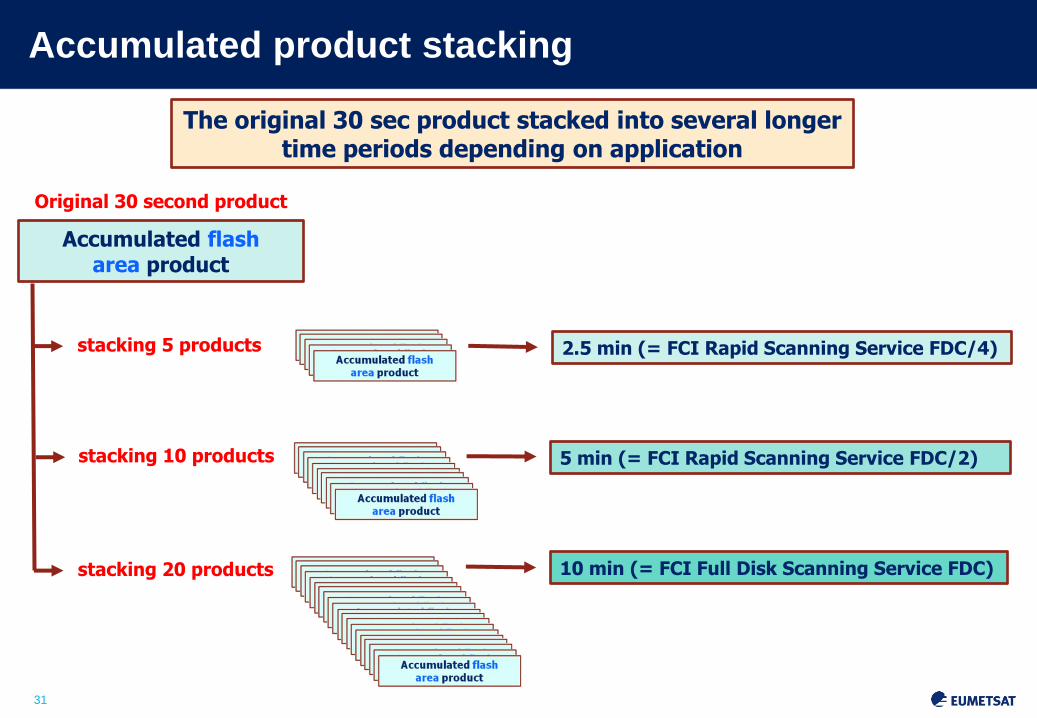
Accumulated product stacking
Accumulated flash area product
The original 30 sec product stacked into several longer time periods depending on application
10 min (= FCI Full Disk Scanning Service FDC)
5 min (= FCI Rapid Scanning Service FDC/2)
2.5 min (= FCI Rapid Scanning Service FDC/4)
Original 30 second product
stacking 5 products
stacking 10 products
stacking 20 products
32
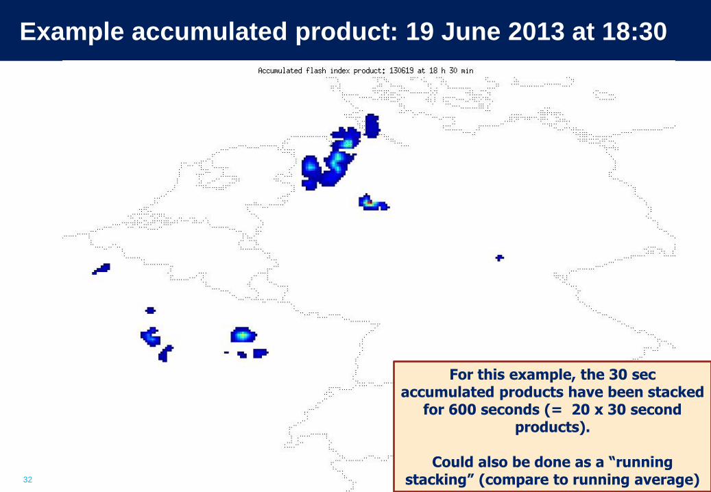
Example accumulated product: 19 June 2013 at 18:30
For this example, the 30 sec accumulated products have been stacked
for 600 seconds (= 20 x 30 second products).
Could also be done as a “running
stacking” (compare to running average)

33
Example accumulated product: 19 June 2013 at 23:30
For this example, the 30 sec accumulated products have been stacked
for 600 seconds (= 20 x 30 second products).
Could also be done as a “running
stacking” (compare to running average)

34
Topics
• Putting Meteosat Third Generation (MTG) into context
• Lightning monitoring from space – how does the concept work
• MTG Lightning Imager • Design and characteristics
• User products
• Proxy data development
• Summary

35
MTG LI Proxy Data – data available before launch
• MTG LI is without heritage in GEO orbit, and the closest
comparison is the Lightning Imaging Sensor (LIS) on TRMM –
currently still in operation
• However, LIS flying on LEO orbit can only monitor storms for less
than 2 minutes at a time (and without European coverage)
• Use of ground-based Lightning Location System (LLS) networks
as a source of proxy data is not straightforward, as they are based
on Radio Frequency (RF) observations of lightning and depending
on the RF band (VHF, VLF, LF) they are sensitive to different
parts of the lightning process
• A combination of optical + RF observations has been selected for
proxy data generation

36
MTG LI Proxy Data – current approach
• The best compromise is to use ground-based lightning data, but
converted to optical pulses based on case study comparisons with
LIS data.
• One of the networks in operation in Europe (LINET) is currently
the main source of such proxy data for the LI activities.
• LINET data has been compared in measurement campaigns to
other ground-based systems and to LIS
• As an outcome, a model for transforming the LINET stroke data
into optical emission (“pulses”) has been created

37
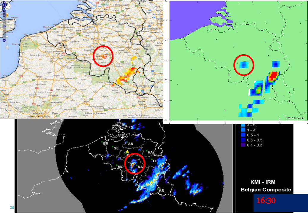
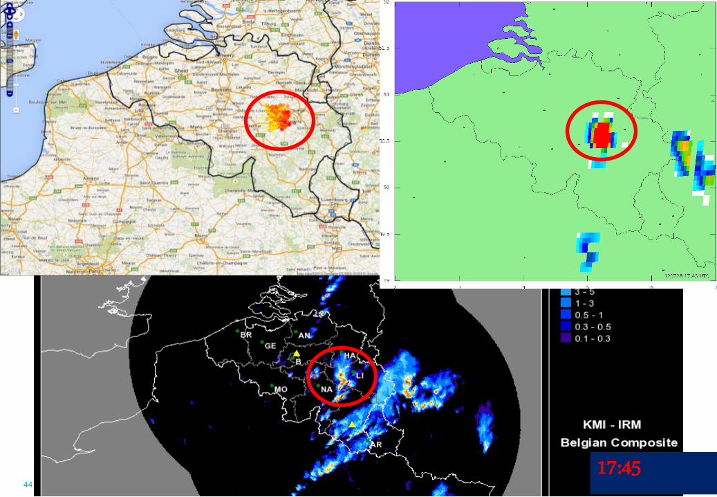
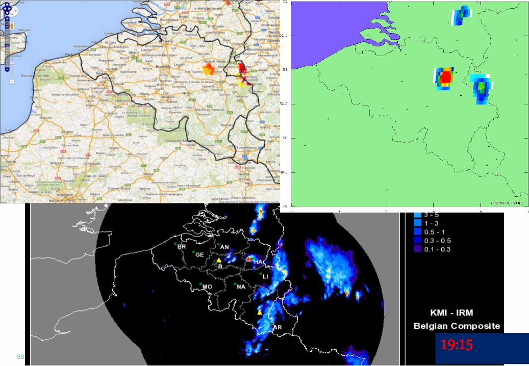
Proxy data examples
• In the following slides a comparison created by RMI (Belgium) is shown. It consists of:
• Top-right panel: • RMI ground-based data: combination of SAFIR and LS700x
sensors placed in Belgium and also in France, Netherlands and Germany.
• Top-left panel:
• LI proxy data (L2 accumulated product)
• Based on LIS/LINET transformation statistics, taking into account the varying DE of LINET in the coverage area
• Bottom panel:
• Weather radar composite

38
16:15
39
16:30

40
16:45

41
17:00

42
17:15

43
17:30
44
17:45

45
18:00

46
18:15

47
18:30

48
18:45

49
19:00
50
19:15

51
19:30
52
Topics
• Putting Meteosat Third Generation (MTG) into context
• Lightning monitoring from space – how does the concept work
• MTG Lightning Imager • Design and characteristics
• User products
• Proxy data development
• Summary
53
Summary
• The Lightning Imager is a new mission on Meteosat Third Generation, with no heritage in Europe (first GEO mission will be on GOES-R in 2016)
• (almost) Full disk coverage with 4 different detectors
• Homogeneous and continuous observations of lightning flashes with a timeliness of 30 seconds
• To be launched in 2019
• User products consist of • Initial processing data (groups and flashes)
• Accumulated product data
• Proxy data for LI available from 2015 onwards (continuous development)