Embed Size (px)
Citation preview

CHAPTER 1 - GENERAL
1 GENERAL
1.1 Introduction
This document is intended to provide guidance to those performing design for the Bridge Program of the Maine Department of Transportation (MaineDOT). It should provide clarity to the design thought process, and serves as a supplement to the applicable AASHTO standards. It should be used in conjunction with good engineering judgment. This document is a companion volume to the Bridge Program’s “Project Management Guide” and “Bridge Plan Development Guide.”
||
The Mission and Goals of the Bridge Program are on the following page.
June 2007 1-1

CHAPTER 1 - GENERAL
1.2 General Team Approach Guidelines
The Bridge Program is regionally organized into Self-Directed Work Teams (SDWTs), each led by a Project Manager. In addition to the Project Managers, each team is composed of Structural Designers, Design Technicians, a Geotechnical Designer, Construction Residents, Construction Inspectors, a Utility Coordinator, a Mapper, an Appraiser, and a Team Coordinator. The environmental coordination function is managed by the Environmental Coordinator from MaineDOT’s Environmental Office, while survey functions are managed by the regional Survey Coordinator. | Each team member has a specific role that is integral to the success of the project as it moves through the project development process. The Structural Designer and the Geotechnical Designer provide the design expertise, and use the resources of the team to provide input into the decision-making that is part of every design.
1.3 Final Design Issues
1.3.1 Plans, Specification and Estimate (PS&E)
This documentation includes a package of information that is used to prepare the bid documents for advertising a project. The package is prepared by the project team and further assembled by the Contracts Technician within the Program. It includes the following items, with the responsibility of the Designers noted:
1.3.1.1 Plans
The plans consist of complete contract drawings that adequately display the design with enough detail to construct the project. The plans are the responsibility of the Design Technician, but must be reviewed by the Designers for conformance to the design. During the development of the plans, communication is essential to avoid rework. Standard notes are found in Appendix D. Plan layouts and detailing practices can be found in the Bridge Program’s “Bridge Plan Development Guide.” |
1.3.1.2 Structural Design Computations
Detailed design computations from the selected alternate are bound, dated, and submitted by the Structural Designer as part of the PS&E package. Design computations should include all references and assumptions used during design. After submission, they are retained in the Computations file cabinet of the Bridge Program.
June 2007 1-3

CHAPTER 1 - GENERAL
1.3.1.3 Geotechnical Design Computations
Geotechnical design computations are included as an appendix of the Geotechnical Design Report. Design computations include all references and assumptions used during design. After completion of the project, the geotechnical file is retained in the Materials, Testing, and Exploration archives in Bangor.
1.3.1.4 Bridge Ratings
Each bridge must be rated by the Structural Designer with a live load rating using the Load and Resistance Factor Rating (LRFR) method. Refer to the Manual for Condition Evaluation of and Load and Resistance Factor Rating (LRFR) of Highway Bridges, October 2003, with interims, for guidance in the live load rating calculation.
||||
1.3.1.5 Special Provisions
In most cases, Supplemental Specifications, commonly used Special Provisions, and/or project specific Special Provisions will be necessary to complement the Standard Specifications. Current Supplemental Specifications and commonly used Special Provisions are available for review. The Designers review and format these specifications for necessary inclusion in the contract documents. If project specific specifications are warranted, the Designers write and format them for the PS&E Package. The Project Manager may be involved in writing some project specific specifications that are not design related.
1.3.1.6 Engineer’s Estimate
This confidential document consists of a detailed estimate of quantities and costs necessary to construct the project. Typically, the Design Technician, with input from the Designers and Project Manager, develops the pay item list and computes the estimated quantities. The Design Technician then inputs the quantities into ESTIMATOR, which will provide automatic weighted average costs for each of the pay items. The Designers are responsible for reviewing those costs and adjusting them where needed, using engineering judgment. For a complete guide to developing an estimate or check, refer to the Bridge Program’s “Bridge Plan Development Guide.”
||
June 2007 1-4

CHAPTER 1 - GENERAL
Bridge Information Form Project
PIN Bridge Number Location
Bridge Name
Project Manager Lead Designer
Lead Technician Resident
Design Code LRFD LFD Other (explain)__________________
Bridge Parameters
Number of Spans Multiple Span Configuration
Number of Sidewalks Bridge Length (CL Brg Abut to CL Brg Abut) FT |
Buried Structure Total Span Length ( use clear spans) FT Skew °
Bridge Width (Fascia-to-Fascia) FT Roadway Width (Curb-to-Curb or Rail-to-Rail) FT
Buried Structure Barrel Length FT Beam Spacing FT
Slab Thickness IN Approach Length (inc. buried structure, but exc. bridge) FT
Scope Work Attribute BIKEWAY Consultant X-LARGE || BRIDGE CONSTRUCTION-NEW Consultant LARGE BRIDGE CULVERT REHABILITATION Consultant MEDIUM BRIDGE CULVERT REPLACEMENT Consultant SMALL BRIDGE DECK REHABILITATION Over Water Replace. X-LARGE BRIDGE DECK REPLACEMENT Over Water Replace. LARGE BRIDGE IMPROVEMENT Over Water Replace. MEDIUM BRIDGE PAINTING Over Water Replace. SMALL BRIDGE RAIL & CURB IMPROVEMENT Over Water Replace. X-SMALL BRIDGE REHABILITATION Overpass Replace. LARGE BRIDGE REMOVAL Overpass Replace. MEDIUM BRIDGE REPLACEMENT Rehab X-LARGE BRIDGE SUBSTRUCTURE REHAB. Rehab LARGE BRIDGE SUPERSTRUCTURE REPLACE. Rehab MEDIUM BRIDGE WEARING SURFACE REPLACE. Rehab SMALL BRIDGE WIDENING Paint SIMPLE TEMPORARY BRIDGE Paint COMPLEX Other (explain) Other (explain)
June 2007 1-5

CHAPTER 1 - GENERAL
Bridge Information Form Estimated Quantities
Volume of Abutment Concrete CY ||Volume of Pier Concrete CY ||
Volume of CIP or Precast Rigid Frame Concrete CY ||Volume of Structural Slab Concrete CY ||
Total Length of Concrete Beams/Girders FT Weight of Structural Steel LB
Weight of Bituminous on Bridge LB Weight of Substructure Rebar LB
Weight of Superstructure Rebar LB Buried Structure Type Structural Steel Pipe or Pipe Arch Structural Steel Plate Arch or Frame with CIP Footings Structural Steel Frame with Metal Footings or Bottom Plate Structural Aluminum Pipe or Pipe Arch Structural Aluminum Plate Arch or Frame with CIP Footings Structural Aluminum Frame with Metal Footings or Bottom Plate | Precast Concrete Frame on Concrete Footings Precast Concrete Box Cast-in-Place Rigid Frame or Arch Plastic Pipe Other (explain)_____________________________________
Superstructure Type (Primary Load-Carrying Members) Steel - Rolled Beam Suspension Steel - Welded Constant Depth Girder Cable-Stayed Steel - Welded Haunched Girder Steel - Through Truss Steel - Rolled Beam and Welded Girder Steel - Pony Truss Steel - Welded Box Girder Steel - Deck Truss Precast Prestressed Voided Slab Timber - Through Truss Precast Prestressed Nonvoided Slab Timber - Pony Truss Precast Prestressed Butted Box Beam Timber - Deck Truss Precast Prestressed Spread Box Beam Timber - Covered Precast Prestressed New England Bulb Tee Timber - Solid Sawn Beam Precast Prestressed AASHTO I Girder Timber - Glulam Beam CIP Concrete - Slab Timber - Glulam Direct Span CIP Concrete - T-Beam FRP Reinforced Glulam Beam | CIP Concrete - Open Spandrel Arch Other (explain) Post-Tensioned Concrete - Segmental Box Inverset
Wearing Surface Type Bituminous with Membrane Waterproofing Concrete - Integral | Bituminous with HP Membrane Waterproofing Concrete - Unreinforced | Bituminous over Fill on Buried Structure Concrete - Reinforced | Rosphalt Other (explain) | Timber |
June 2007 1-6

CHAPTER 1 - GENERAL
o Inspection/Maintenance - How will the bridge be inspected and repaired? Refer to Section 2.9.6 Maintainability.
o Bollards – Bollards may be used to control or limit access. Bollards are usually timber or steel posts spaced at about 5 foot spacing that prevent large vehicles from going onto a bridge. The spacing of the bollards can be reduced to 3 feet clear to prevent virtually all motorized vehicles from using the bridge. Removable bollards should be considered if emergency or maintenance vehicles will occasionally use the bridge.
||
o Rail - Bridges that may be used by snowmobiles should use at least a 42” bicycle height bridge rail. The use of a rub rail is highly recommended to prevent bicycle handlebars from catching on the bridge rail. ||
||
The Structural Designer should also consider the use of security fencing, lighting, and attached utilities on the bridge. The load capacity of the bridge should be clearly posted on or near the bridge in accordance with MUTCD.
1.7 Aesthetics
1.7.1 General
Aesthetics involves more than just surface features such as color and texture. It includes the visual and perceptual effect made by the bridge as a total structure, as well as the effect made by its individual parts. Bridges affect their surroundings by virtue of their size, shape, line, color, and texture. All structures should be designed with consideration of site-specific features to create designs that provide function as well as a pleasing appearance. The key is to create a distinguished structure without spending excessive resources.
Bridges are usually viewed from one of two places, either from the roadway as a user, or from the side. For those bridges rarely seen from the side, aesthetic considerations are limited to the appearance of the rail, sidewalk, curb, and wearing surface. For other bridges, the view of the bridge from the side should be considered in the design. The nature of the surroundings may influence the aesthetic design choices, whether the location is urban, rural, industrial, or coastal.
1.7.2 Design Considerations
Consistency in the use of flares and tapers in bridge components will result in a more harmonic structure. For example, if a column is flared to be wider at
June 2007 1-15

CHAPTER 2 – PRELIMINARY DESIGN
Program Funding Level – Enter either “Construction” or PCE level
||
Approximate Cost - Enter the cost figures for Program Amount, Total Available Funding, Total Project Need, and Future Project Need under the appropriate headings.
Projobta Utiliobta Addor n ExcStanonlyvia tredusup Com
2.1.6 S
This formpermittinhistoricainclude the requ
2.1.7 S
This is aproject ralternatithat area discusreasoninof geoteproject.
June 2007
Commentary: The estimated cost of the project is located in 4 places within the PDR: the program funding table, summary of preliminary design, preliminary plan, and the cost estimate.
ect Fiscally Approved – Signature of Assistant Program Manager is ined here prior to proceeding with any further work.
ties - List the known utilities in the project limits. The utility list may be ined from the Utility Coordinator or the utility data base.
itional Soils Information and Additional Field Survey - Indicate whether ot the information is required.
eption to Standards - List any exceptions to Federal or State dards that either requires approval from FHWA (for NHS projects ), the Engineer of Design, or the Bridge Program management team he Coachpoint process. Examples of exceptions to standards are ced bridge widths, omitting of the leveling slab on butted precast
erstructures, and reduced hydraulic clearances.
ments - This is for comments by the Engineer of Design.
ummary of Expected Impacts
provides a summary of the expected impacts and the required g for the recommended project. These impacts may be right-of-way, l, archeological, environmental, etc. The required permitting may Coast Guard, FAA, and the various environmental permits. Filling in ired information for this form will be a project team effort.
ummary of Preliminary Design
summary of the Preliminary Design performed to determine the ecommendations. It should describe, in an orderly fashion, the ves considered, with a summary of the assumptions and comparisons pertinent to the justification of the recommendation. It should include sion of bridge width, alignment, and maintenance of traffic, with the g used to arrive at the recommendation. It may include a discussion chnical, environmental, or utility issues, if these are pertinent to the
2-6

CHAPTER 2 – PRELIMINARY DESIGN
2.3.10.6 Fish Passage
MaineDOT’s fish passage policy and design guide is available at the following website: http://www.maine.gov/mdot/environmental-office-homepage/other_environmental.php. Designers should refer to this guide to insure that fish passage is maintained.
2.3.11 Scour
2.3.11.1 New Bridges
Commentary: Flooding is the most common cause of bridge failure, with the scouring of bridge foundations being the most common failure mechanism. The catastrophic collapse of the Interstate 90 crossing of Schoharie Creek near Amsterdam, NY on April 5, 1987, is one of the most severe bridge failures in the U.S. Two spans fell into the water after a pier supporting the spans was undermined by scour. Five vehicles plunged into the creek killing 10 people. The National Transportation Safety Board concluded that the bridge footings were vulnerable to scour because of inadequate riprap around the base of the piers and a relatively shallow foundation. The I-90 collapse focused national attention on the vulnerability of bridges to failure from scour and resulted in revisions to design, maintenance, and inspection guidelines. MaineDOT initiated a scour-screening program in 1987 in response to FHWA Technical Advisory TA 5140.20 (succeeded by TA 5140.21 and TA 5140.23). The advisories ultimately require that a master list be generated of all bridges that require underwater inspection, and that all applicable bridge foundations be evaluated and prioritized according to their vulnerability to scour damage. Reliable equations to compute local scour depths are available for piers. A report by the USGS titled “Observed and Predicted Scour in Maine” is available at the following website http://me.water.usgs.gov/wrir02-4229.pdf. The report confirms that the local pier scour predicted by the latest version of the CSU equation in the Hydraulic Engineering Circular 18 Fourth Edition May 2001 on page 6.2 are reasonable.
|||||
||
Bridges over waterways with scourable beds should be designed to withstand the effects of scour from a superflood (a flood exceeding Q100) without experiencing foundation movement of a magnitude that requires corrective action. A scour analysis will be performed for all bridge-type structures using the methods in the latest version of HEC-18. The design flood for scour is the lesser of Q100 or the overtopping flood. Maximum scour depths will be produced by the overtopping flood. Scour should also be computed for the superflood, defined as Q500 or the overtopping flood if it is between Q100 and Q500. Q500 can be estimated as 1.18 times the magnitude of the Q100, if Q500 cannot be computed by other means.
The bridge foundation should be designed for the normal factor of safety as specified in AASHTO Standard Specifications below the scour depths estimated for Q100. The bridge foundation should have a factor of safety of 1.0 for scour produced by the superflood. The footings should be placed a minimum of 2 feet below the design flood scour level. Where pile bents are used, the design friction or point bearing should be achieved below the
June 2007 2-34

CHAPTER 2 – PRELIMINARY DESIGN
• Current right-of-way limits
• Geometric alignment
• Traffic volume
• Propensity for growth
2.8.1.2 Collector Roads
The approach guardrail (attached and immediate to the bridge) should be set at the same width as the bridge rail. For bridges on collector roads with extensive approaches, refer to the “MaineDOT Highway Design Guide” for appropriate shoulder widths and guardrail offsets.
||
2.8.1.3 Arterials
Roadway widths for approaches on arterials should comply with the latest AASHTO A Policy on Geometric Design of Highways and Streets.
2.8.2 Guardrail
2.8.2.1 General
On the NHS, terminal ends must meet the requirements of NCHRP 350 in conjunction with either guardrail type 3d on Interstate projects and 3c on non-Interstate NHS. Refer to Section 10 of the “MaineDOT Highway Design Guide” for further guidance. On non-NHS roadways with an AADT>500, use a NCHRP 350 compliant system for an end treatment with guardrail type 3 or 3b as appropriate. On non-NHS roadways with AADT of 500 or less, use the Low Volume Guardrail End with guardrail type 3 or 3b as appropriate. For more information on guardrail types, refer to the Standard Specifications and Standard Details.
||||
2.8.2.2 Guardrail Treatment on Local Roads |Bridge approach guardrails protect motorists from roadside hazards such as non-negotiable foreslopes, telephone poles, trees, streams, and rivers, and provide safe transitions to the bridge rail system. For guidance on bridge rail systems, refer to Section 4.4 Bridge Rail. Termination of these systems is controlled by the steepness of the foreslopes, location of obstacles, and the geometry of the stream crossings. Termination design criteria are presented in the current edition of the AASHTO Roadside Design Guide and the “MaineDOT Highway Design Guide”. The use of |
June 2007 2-48

CHAPTER 2 – PRELIMINARY DESIGN
these criteria can result in lengthy terminations and can extend projects beyond the lengths required to meet the objective of the project. Bridge projects on local roads are intended to upgrade deficient structures and provide cost effective guardrail systems. This section provides design criteria for local bridge projects that minimize guardrail termination lengths and also eliminate the use of NCHRP 350 compliant end treatments in some instances.
|
The termination and NCHRP 350 compliant end treatment design criteria set forth in this section are intended for use only on roads for which the functional classification is local. Other projects should be designed in accordance with the guidelines and policy set forth in the “MaineDOT Highway Design Guide”.
|
||
Use the following definitions in this section:
• Clear zone: The clear zone is an unencumbered area measured perpendicular to the roadway that allows out of control vehicles leaving the roadway to recover.
• Non-recoverable slope: A slope that motorists can traverse but from which most motorists will be unable to stop or return to the roadway. Slopes that are between 4:1 and 3:1 are considered traversable but non-recoverable.
• Critical slope: A slope on which a vehicle is likely to overturn. Slopes that are steeper than 3:1 are considered critical.
• Recovery area: Sum of the clear zone and the non-recoverable and critical slopes.
• Lateral extent of hazard:
Stream that extends beyond the clear zone: The point where the outer limit of the recovery area intersects with the top of the non-negotiable slope at or near the stream edge. Fixed object such as a tree, pole, etc.: The distance from the edge of the traveled lane to the far side of the hazard.
• Runout path: Theoretical path an out of control vehicle will follow as it leaves the roadway at the point of need.
• Point of need: The last point at the face of guardrail where a vehicle can leave the road and follow the runout path without traversing a critical slope or hitting a Deadly Fixed Object.
June 2007 2-49

CHAPTER 2 – PRELIMINARY DESIGN
Figure 2-3 Point of Need Definition
Figure 2-4 Lateral Extent of Hazard Definition Procedure 2-1 has been developed to determine the proper treatment of the terminal end for the Leading End and Trailing End. Procedure 2-1 Guardrail End Treatment on Local Roads For the Leading End, follow the procedure below.
a. Establish the clear zone distance (Lc) based upon the design future traffic volume and the design speed. (Refer to Table 2-4)
b. Locate the lateral extent of hazard.
c. Establish the runout path and the point of need by extending a line from the limit of hazard point to the face of guardrail at the encroachment angle based upon the design speed. (Refer to Table 2-5)
d. Provide an end treatment beyond the point of need:
AADT > 500: Use an NCHRP 350 compliant end treatment system AADT ≤ 500: Use a low volume guardrail end. The use of NCHRP 350 compliant end treatment systems should be examined on local road projects where maintenance will be provided by the local government. These facilities may not be maintained, and after an NCHRP 350 compliant end treatment system is hit and damaged, it may be more dangerous than a standard flared terminal end.
||
|||
June 2007 2-51

CHAPTER 2 – PRELIMINARY DESIGN
e. Where possible provide a minimum length of 100 feet from the bridge to the end of the guardrail. The length of the project should be extended if necessary to provide this minimum length of guardrail.
A minimum length of guardrail should be provided regardless of the project length to provide adequate protection at the approach rail - bridge rail interface. Guardrail may be extended onto the approach transitions or even beyond the transitions by rehabilitating the existing shoulders and defining a limit of work beyond the end of the transition.
Table 2-4 Clear Zone
Clear Zone (Lc, ft) AADT (Future) 30 mph 40 mph 50 mph
<200 5 7 8 200 to <400 6 8 10 400 to <800 7 10 12 800 to <2000 10 12 14
2000 to <6000 12 15 18 6000+ 14 17 20
Table 2-5 Encroachment Angle
Design Speed Encroachment Angle 30 mph 15° 40 mph 12°
50+ mph 10° For the Trailing End, follow the procedure below.
a. The required clear zone width for the trailing end (measured from the centerline of the road to the lateral extent of the hazard) is within the width of the adjacent lane plus the shoulder for an AADT less than 6000. Stream protection need not be considered unless the AADT equals or exceeds 6000, or unless terrain features (such as a stream which is skewed to or nearly parallel with the roadway) require consideration.
b. Establish the point of need at the face of guardrail adjacent to the first 3:1 slope. (Where the transition from a 3:1 to a 2:1 slope begins.)
c. Provide an end treatment beyond the point of need:
• AADT> 500: Use an NCHRP 350 compliant end treatment system.
|
|• AADT≤ 500: Use a low volume guardrail end.
d. Where possible, provide a minimum length of 50 feet from the bridge to the end of the guardrail.
June 2007 2-52

CHAPTER 2 – PRELIMINARY DESIGN
Other special conditions may also require consideration for guardrail treatment on local roads, including terrain features, approach curves, ditches, intersections, and driveways. Certain terrain features can reduce the need for long guardrail lengths. If the calculated guardrail length exceeds the minimum requirement of 100 feet, examine the terrain along the runout path and within the clear zone. Will a motorist likely avoid the hazard by entering a field or open space before reaching the hazard? Will a motorist likely become hung-up in the brush before reaching the hazard? Is the stream bank flat (3:1 or flatter) and the stream shallow (3 feet or less at normal water) so that the motorist will be safer entering the stream than hitting the guardrail? These features must be evaluated on a project-by-project basis, and proposed guardrail reductions approved by the project team. Longer guardrail lengths may be required to protect vehicles from utility poles and non-breakaway signs located within the clear zone. When an approach curve is present, along with a high accident history, increasing the clear zone width, Lc, may reduce accident potential. For sharp approach curves, the runout path should follow a line tangent to the curve to the lateral extent of hazard. Ditches may affect guardrail length. Trapezoidal approach ditch sections (2 feet wide at the bottom) should have 3:1 or 4:1 (preferred) foreslopes and 2:1 backslopes in areas where the ditches are parallel to the direction of travel. In areas where traffic could be expected to cross the ditch at a sharp angle such as the outside of a curve, the slopes should be flattened to conform to the recommendations in the AASHTO Roadside Design Guide. If intersections, drives, or field entrances are found within the runout length, adequate sight distance must be provided. Guardrail should be wrapped into the entrance and terminated with a standard terminal end. NCHRP 350 compliant end treatment systems should be used on side roads where AADT exceeds 500.
||
The following Example 2-5 illustrates concepts shown in Procedure 2-1.
June 2007 2-53

CHAPTER 2 – PRELIMINARY DESIGN
Example 2-5 Guardrail End Treatment on Local Roads Given: Design Speed= 45 mph AADT= 650 11 ft Lane width 4 ft to face of rail 3 ft from face of rail to berm Problem: Determine the point of need for the leading and trailing ends. Solution: Follow the Guardrail Treatment on Local Roads Criteria. Refer to Figure
2-5 and Figure 2-6. Leading End Step 1: Determine the clear zone distance from Table 2-4. The 45 mph design speed must be rounded to the next highest design speed given in the table, 50 mph. Lc = 12 ft Step 2: Determine the lateral extent of hazard. In this example, the stream is the hazard. Since the stream extends beyond the recovery area, the lateral extent of hazard is the point where the limit of the recovery area meets the first non-recoverable slope (steeper than 4:1) at the edge of the stream. Step 3: Establish the runout path. For the 45 mph design speed, round to 50 mph then select the encroachment angle from Table 2-5. Encroachment angle is 10° Step 4: Locate the point of need. Extend the runout path to the face of guardrail. The intersection is the point of need. The length of guardrail exceeds the minimum of 100 ft.
||
Step 5: Provide an end treatment. The AADT exceeds 500, therefore use an NCHRP 350 compliant end treatment system. The last 3:1 foreslope should be located 50 ft from the point of need. The slope should be transitioned to 2:1 in 50 ft. Trailing End Step 1: From above, the required clear zone is 12 ft. Since the distance from the edge of the traveled lane (in this case the centerline of the roadway) to the face of rail of 15 ft is greater than the clear zone, stream protection is not necessary. Step 2: Establish the point of need as the last 3:1 slope. In this case the side slope 50 ft from the bridge is 3:1, therefore use 50 ft from the bridge to the point of need.
||
Step 3: Since the AADT of 650 is more than 500, use an NCHRP 350 compliant end treatment system. Step 4: The length of rail is 100 ft, exceeding the 50 ft minimum distance from the bridge.
June 2007 2-54

CHAPTER 2 – PRELIMINARY DESIGN
||||
||||
Figure 2-5 Point of Need Example
June 2007 2-55

CHAPTER 2 – PRELIMINARY DESIGN
2.9.7 Historical/Archeological Issues
It is critical that any project that has historical or archeological interest is flagged early in the process. Working with the Maine Historic Preservation Commission (MHPC) and relevant historic districts as the design is developed will save considerable time in the process.
2.9.8 Cost
The Structural Designer should attempt to find the lowest cost option that satisfies the requirements of the applicable code, MaineDOT guidelines, and the traveling public, but does not sacrifice quality. First cost must be considered, as well as life cycle cost in some cases (refer to Section 2.2 Economic Comparisons). The program cost should be identified, and every attempt made to design a project that falls within that budget.
2.9.9 Aesthetics
The consideration of aesthetics in every design is encouraged. Often there are low cost methods that can be incorporated into a design that can greatly increase the aesthetic value of the project. Refer to Section 1.7 Aesthetics for more discussion.
|||||||||||||||||||
2.10 Subsurface Exploration Programs
2.10.1 Boring Program
The boring program and geotechnical investigation is developed by the Geotechnical Designer. The boring program includes a summary of all geotechnical activities such as the boring identification number, boring station and offset (if available), boring termination requirements, sampling requirements, and in situ testing requirements. It also includes a plan showing the proposed boring locations for the project containing the following information:
o Title block
o 1:25 plan view of the existing structure and the proposed structure (if known)
o Proposed boring locations indicated by the standard symbol
Each boring location must have a unique boring identification number in the following format: XX-YYYY-ZZZ. The X terms in the boring number will be “BB” for bridge borings. The Y terms will be the first letter of the town(s) and
June 2007 2-64

CHAPTER 2 – PRELIMINARY DESIGN
|||||||||||||||||||
|||||||||||||||||||||
the initials of the crossing. The Z terms will be a 100, 200, 300, etc. series number. For example, the first series of borings for a bridge crossing Noname River in Anytown is designated as BB-ANR-101, BB-ANR-102, etc. Any additional borings conducted at a site after the initial borings have been completed will be designated as 200 series, 300 series and so forth. One copy of the boring program is submitted to the Structural Designer. One copy will remain in the Bridge Geotechnical File. Two copies will be sent to MaineDOT Materials, Testing, and Exploration Division (MTED) in Bangor: one for the MTED file and the other for use in the field.
2.10.2 Exploration Program Objectives
For traditional bridge structures, the cost of a boring is small in relation to the overall foundation cost. The knowledge gained from borings permits the use of appropriate design techniques and allows for less conservative designs. Without adequate boring data, evaluating geotechnical alternatives becomes more difficult, and the Geotechnical Designer must rely on more conservative designs. Planning a boring program should include:
o Determining the depth and location of borings, test pits, and/or auger probes, as necessary
o Establishing the methods of soil sampling and testing
The number, depth, spacing, and character of tests to be made in any individual boring program are dependent upon site conditions, type of structure, the structure’s performance, and design requirements. Due to the site specific nature of each subsurface exploration, there is no preferred approach for establishing the program. Certain general principles guiding the development of a subsurface investigation, such as soil sampling and in-situ testing, are a necessary part of every investigation.
The boring program is established by the Geotechnical Designer and reviewed with the Structural Designer. A boring program based on these guidelines will produce the minimum geotechnical information to evaluate a typical bridge structure site.
2.10.3 Preliminary and Final Borings
A subsurface investigation may be required during the preliminary stages of a project at a time when the alignment, the location of abutments or the location and number of piers are not yet established. In these instances, preliminary borings may be conducted to yield only sufficient soil information to enable the Structural Designer to:
June 2007 2-65

CHAPTER 2 – PRELIMINARY DESIGN
||||||||||||||||||||||||||||||||||||||||
o Provide subsurface information for development of foundation alternatives for the PDR
o Establish the vertical and horizontal roadway alignment alternatives
o Locate proposed substructure units
o Prepare the preliminary cost estimates
At a minimum, the preliminary boring program shall include: o One boring per substructure unit
o Consideration of a 10 foot deep rock core should be made at this time if the information would influence the foundation design
Preliminary borings should not be used for final design purposes. A final boring program should be developed and carried out in accordance with the frequency and depth requirements in Table 2-10, Table 2-11, and this Section. If the project alignment, location of abutments, and location and number of piers is established with certainty during preliminary design stage a preliminary boring program should not be conducted.
2.10.4 Number and Layout of Borings
Borings shall be taken for every: o bridge
o retaining wall
o metal pipe, plate arch, pipe arch, or box, with a span greater than 8 ft
o concrete arch or box with a span greater than 8 ft
o high-mast light foundation
o single support cantilever sign foundation
o other traffic or sign supports which require a foundation.
The borings should be performed using cased, wash boring techniques. In some instances, open-hole hollow stem auger and/or solid stem auger drilling methods may be used. For final design, the number and layout of borings should be determined as suggested in Table 2-10. The guidelines shown in Table 2-10 are the minimum requirements to evaluate a site for design. The number and layout
June 2007 2-66

CHAPTER 2 – PRELIMINARY DESIGN
of borings; however, will also depend on the phase of the investigation being performed. For feasibility studies or preliminary PDR investigations, fewer borings and very wide boring spacings may be acceptable, especially if the subsurface conditions are uniform. The location and frequency of drilling and sampling depend on the type and critical nature of the proposed structure, the soil and bedrock characteristics, the variability in subsurface conditions, the loads to be imposed on the foundations soils, and the structures performance and design requirements. Table 2-10 is intended to be used as a guideline. Actual determination of number and layout of borings is at the Geotechnical Designer’s discretion.
Table 2-10 Guidelines for Boring Number and Layout
Foundation Type/ Geotechnical Feature
Boring Layout
Bridge Foundations
For piers and abutments less than 100 feet in length, provide a minimum of one boring at each pier and abutment. Boring locations should be staggered diagonally at opposite ends of adjacent footings. For piers and abutments over 100 feet in length, provide a minimum of two borings. Borings should be located at the extreme corners of each substructure. For spread footings on sloping bedrock surfaces, additional borings or probes may be required. Additional borings should be provided in areas of erratic subsurface conditions.
Retaining Walls For retaining walls up to 100 feet in length, provide a minimum of one boring at the wall end. For abutment wingwalls which measure less than 30 feet in length, the abutment borings may suffice. For retaining walls more that 100 feet in length, the spacing between borings should be no greater than 100 feet. For walls ≤20 feet high, use a maximum boring spacing of 100 feet. For walls ≥ 20 feet high use maximum boring spacing of 50 feet, regardless of the wall length.
||||||||||||||||||||||||||||||||||||||||
June 2007 2-67

CHAPTER 2 – PRELIMINARY DESIGN
Additional borings inboard and outboard of the wall line to define conditions at the toe of the wall and in the zone behind the wall to estimate lateral loads and anchorage capacity may also be required.
Roadways The spacing of borings along the roadway alignment generally should not exceed 200 feet. The spacing and location of the borings should be selected considering the geologic make up of the soil and bedrock continuity within the project area. The objective is to define the vertical and horizontal boundaries of distinct soil and rock units within the project limits.
Metal Pipes Metal Arches Metal Box Culverts Concrete Box Culverts
Provide a minimum of one boring at each buried metal pipe, arch, box culvert, and concrete box culvert, with a span greater than 8 feet. Additional borings should be provided for long culverts or in areas of suspected erratic subsurface conditions. For culverts up to 50 feet in length, two borings are required. For culverts longer than 50 feet, three borings are required.
Cuts A minimum of one boring should be performed for each cut slope less then 100 feet in length. For cuts more than 100 feet in length, the spacing between borings along the length of the cut should generally be between 100 and 200 feet. At critical locations and high cuts, provide a minimum of three borings in the transverse direction to define the existing geological conditions for slope stability analyses. In an active slide area, place at least one boring upslope of the sliding area.
Embankments A minimum of one boring per 100 feet should be performed for each embankment. For embankments more than 100 feet in length, the spacing between borings along the length of the embankment should generally be between 100 and 200 feet. At critical locations and high embankments, provide a minimum of three borings in the transverse direction to
|||||||||||||||||||||
|||||||||||||||||||
June 2007 2-68

CHAPTER 2 – PRELIMINARY DESIGN
define the existing geological conditions for slope stability analyses. In an active slide area, place at least one boring upslope of the sliding area.
Staged Construction
Provide at least one boring to determine the constructability and design of staged construction sheet piling.
2.10.5 Depth of Borings
Borings shall be advanced to a depth which will provide sufficient information to evaluate bearing capacity, settlement, slope stability, pile capacity, and other geotechnical design factors as required by the site conditions. Table 2-11 provides guidelines for selecting minimum boring depths. Ultimately, the final boring depth at a specific site is at the discretion of the Geotechnical Designer. Field judgment exercised during the investigation phase will further define the boring program and ultimately satisfy the investigation requirements necessary for design of the foundation system. Frequently, it may be necessary to extend borings beyond the minimum depths shown in Table 2-11. Deeper borings can allow for better definition of the geologic setting at the site, assist in determining the depth and engineering characteristics of soft soil, and assure that sufficient information is obtained when the structure requirements are not clearly defined at the time of drilling. Where borings are drilled to bedrock, it is recommended that a minimum 10 foot length of bedrock core be obtained to verify that the borings has not terminated on or within a boulder. Subsurface investigation programs must be flexible to adjust to variations in subsurface conditions encountered during drilling. On critical projects, the Geotechnical Designer should be present during the field investigation in order to make field decisions regarding boring depth, in-situ testing and additional borings. Open lines of communication with the Structural Designer to discuss unusual field findings and changes are necessary during the investigation program.
Table 2-11 Minimum Requirements and Guidelines for Boring Depths Areas of Investigation
Boring Depth
Bridge Foundations - Spread footings
No boring shall be less than 10 feet below the preliminary bottom of footing elevation. For abutments on slopes, borings shall extend at least 20 feet below the proposed bottom of footing elevation.
||||||||||||||||||||| |||||||||||||||||||
June 2007 2-69

CHAPTER 2 – PRELIMINARY DESIGN
For isolated footings of length L and width B, where L≤2B, borings shall extend a minimum of two footing widths (2B) below the footing bearing level. For isolated footings where L≥ 5B, borings shall extend a minimum of five footing widths (5B) below the footing bearing level. For 2B ≤ L ≤5B, minimum boring depths shall be determined by liner interpolation between a depth of 2B and 5B below the footing bearing level. For spread footings founded directly on bedrock, the length of the bedrock core should be no less than 10 feet. Selection of boring depths at river and stream locations must consider the potential scour depth of the stream bed.
Bridge Foundations - Deep Foundations
A minimum of one boring shall be made to bedrock under each substructure unit that is founded on piles or shafts. For piles or shafts bearing on soils, borings shall extend below the anticipated pile or shaft tip elevation by a minimum of 20 feet, or a minimum of 2 times the maximum pile group dimension, whichever is deeper. For piles bearing on bedrock, a minimum of 10 feet of bedrock core shall be obtained at each boring location to verify that the boring has not terminated on a boulder, and to determine RQD for a 10 feet bedrock core. For drilled shafts supported in or on bedrock, a minimum of 10 feet of bedrock core, or a length of bedrock core equal to at least 3 times the shaft diameter, shall be extended below the preliminary shaft tip elevation.
Retaining Walls Borings shall have a minimum depth of 0.75 to 1.5 times the height of the wall below the anticipated bottom of footing. Where the soil type indicates possible deep stability or settlement problems, borings should extend to an underlying competent stratum. Boring depth for sheet piling should extend below the final ground line to a minimum of 2 times the exposed
|||||||||||||||||||
|||||||||||||||||||||
June 2007 2-70

CHAPTER 2 – PRELIMINARY DESIGN
|||||||||||||||||||
|||||||||||||||||||||
wall height. For wall supported on deep foundations, use the criteria above for deep bridge foundations.
Roadways Borings shall have a minimum depth of 5 feet below the proposed subgrade level.
Culverts, Boxes, Arches
Borings shall have a minimum depth equal to twice the backfill embankment height, unless a hard stratum is encountered above this depth. Where soft strata are encountered which may present stability or settlement concerns, the borings should extend to an underlying competent stratum.
Cuts Borings shall extend a minimum of 15 feet below the anticipated depth of the cut at the ditch line. Boring depths should be increased where base stability is a concern due to soft soils, or in locations where the base of the cut is below groundwater level.
Embankments Borings shall extend a minimum depth equal to twice the embankment height, unless a hard stratum is encountered above this depth. Where soft strata are encountered which may present stability or settlement concerns, the borings should extend to an underlying competent stratum.
Staged construction
The boring depth for sheet piling should extend a minimum of 2 times the exposed wall height.
2.10.6 Standards and Guidelines for Borings, Sampling and In-Situ Testing
Subsurface field exploration by borings should be conducted in accordance with applicable FHWA procedures, MaineDOT procedures, and the AASHTO/ASTM standards listed in Table 2-12. Standard procedure should always be followed as improvisation of investigative techniques may result in erroneous or misleading results which may have serious consequences on the interpretation of the field data. All sampling techniques and intervals shall be approved and/or determined by the Geotechnical Designer during drilling activities. Borings for structure foundations and geotechnical features shall be cased wash borings having a minimum diameter of 3.0 inches. Standard penetration tests (SPT) should be performed for each boring at 5 foot intervals and at
June 2007 2-71

CHAPTER 2 – PRELIMINARY DESIGN
changes in strata. Continuous sampling is recommended for the top 15 feet when footings are to be placed on native soils. Soft ground conditions will require undisturbed sample explorations or in-situ testing. Undisturbed Shelby tube samples should be obtained at 5 foot intervals in at least one boring in cohesive soils. For cohesive soils greater than 30 feet in depth, tube samples interval can be increased to 10 feet. In silt-clay deposits, in situ vane shear strength tests are recommended at 5 to10 foot intervals. A minimum of 10 feet of bedrock shall be cored in borings reaching bedrock. The minimum diameter of bedrock core shall be 1.88 inches (NQ-size). The Rock Quality Designation (RQD) shall be calculated for all rock cores prior to transportation of the core. Visual identification of the soil samples shall be performed by the field inspector in accordance with the Maine Department of Transportation “Key to Soil and Rock Descriptions and Terms”, April 2004. All pertinent boring identification data, test data, visual classification of soil and rock, and changes in soil stratum shall be recorded in accordance with the “MaineDOT Soil/Rock Exploration Log”, and the MaineDOT “Visual Identification Rock Cores Log”.
Table 2-12 AASHTO, ASTM, and MaineDOT Standards for Field
Investigations
Standard
AASHTO ASTM MaineDOT Test / Practice
D 1452 Practice for Soil Investigation and Sampling by Auger Borings
T 206 D 1586 Method for Penetration Test and Split-Barrel Sampling of Soils
T 207 D 1587 Practice for Thin-Walled Tube Sampling of Soils for Geotechnical Purposes
T 223 D 2573 MaineDOT “Vane Shear Testing Recommended Practice”, Feb. 2001
Test Method for Field Vane Shear Test in Cohesive Soil
D 2113 Practice for Rock Core Drilling and Sampling for Site
||||||||||||||||||||||||||||||||||||||||||
June 2007 2-72

CHAPTER 2 – PRELIMINARY DESIGN
||||||||||||||||||||||||||||||||||||||||
Investigation D 4220 Practice for Preserving and
Transporting Soil Samples D 5079 Practice for Preserving and
Transporting Rock Core Samples
MaineDOT “Key to Soil and Rock Descriptions and Terms”, rev. April 2004
Practice for Visual Description of Soils and Rock
D 6032 Method for Determining Rock Quality Designation of Rock Core
T 86 D 420 Standard Guide to Site Characterization for Engineering Design and Construction Purposes
MaineDOT Soil/Rock Exploration Log
Practice for Visual Description of Soils and Rock
MaineDOT Visual Identification Rock Cores Log
Practice for Visual Description of Rock Core
2.10.7 Presentation of Subsurface Exploration Data
2.10.7.1 Boring Log Sheets
Logs of all borings, test pits, and/or auger probes taken at a site must be transcribed to plan sheets. All borings conducted at the site shall be represented, including exploratory borings and those conducted for abandoned alignments. Laboratory test results should also appear on the boring logs. The boring logs shall be drafted using the format of the MaineDOT LOGDRAFT Boring Log. LOGDRAFT supports output of AutoCAD DXF Files, which aids in the transcription of the boring logs to plan sheets with a title block called “Boring Logs”.
2.10.7.2 Boring Location Plans and Interpretive Subsurface Profiles
A longitudinal profile graphically depicting the subsurface conditions should be developed from all field explorations and lab tests. Approximate soil layer boundaries and accurate soil descriptions should be established for all
June 2007 2-73

CHAPTER 2 – PRELIMINARY DESIGN
|||||||||||||||||||
|||||||||
soil deposits. If the boring is terminated in bedrock, the approximate bedrock profile and accurate bedrock description should be established. Subsurface profiles should include the visual description of each soil deposit observed, bedrock description and profile, groundwater level, and special items such as boulders or artesian pressure, as applicable. The subsurface profile can be presented with reasonable accuracy and confidence at the location of the borings. The Geotechnical Designer may present a continuous subsurface profile that shows an interpretation of the location, extent and nature of subsurface deposits between borings. Caution should be exercised in the presentation and interpretation of soil and geologic data between borings. The location of the borings, augers, and/or test pits, as applicable, and the subsurface profile should be presented on sheets with a title block called “Boring Location Plan and Interpretive Subsurface Profile”. The Geotechnical Report should be accompanied by the following plan sheets:
o Boring Logs
o Boring Location Plan
o Interpretive Subsurface Profile
Where possible, these sheets may be combined to reduce the number of plan sheets.
June 2007 2-74

CHAPTER 2 – PRELIMINARY DESIGN
References
AASHTO, 2001, A Policy on Geometric Design of Highways and Streets, Washington, DC AASHTO, 2002, Roadside Design Guide, Washington, DC |AASHTO, 2002, Standard Specifications for Highway Bridges, Seventeenth Edition, Washington, DC American Railroad Engineering and Maintenance of Way Association (AREMA), 2002, Manual for Railway Engineering, USA Bodhaine, G. L., 1968, Measurement of Peak Discharge at Culverts by Indirect Methods, U.S.G.S. TWRI Book 3, Chapter A3 Bridge Life Cycle Cost Analysis, Computer program, NCHRP Project 12-43 Cedergren, Harry A. 1967, 1977, 1989, Seepage Drainage and Flow Nets, Third Edition, John Wiley & Sons New York DARWin™ Pavement Design System, 1993, AASHTO, Computer program Federal Highway Administration, 2001, Bridge Scour and Stream Instability Countermeasures - Experience, Selection, and Design Guidance, Hydraulic Engineering Circular No. 23 (HEC #23), Publication No. FHWA NHI-01-003, March Federal Highway Administration, 1995, Evaluating Scour at Bridges, Hydraulic Engineering Circular No. 18 (HEC #18), Publication No. FHWA-IP-90-017, November Federal Highway Administration, 1991, Evaluating Scour at Bridges, Technical Advisory T 5140.23, October 28 Federal Highway Administration, 1985, Hydraulic Design of Highway Culverts, Hydraulic Design Series No. 5 HDS Federal Highway Administration, Hydraulic Engineering Circular No. 14 Federal Highway Administration, 2001 Stream Stability at Highway Structures, Third Edition, Hydraulic Engineering Circular No. 20 (HEC #20), Publication No. FHWA NHI 01-002, March
June 2007 2-75 |

CHAPTER 2 – PRELIMINARY DESIGN
Federal Highway Administration, Runoff Estimates for Small Rural Watersheds and Development of a Sound Design, FHWA Reports - FHWA-RD-77-158 and 159, Volumes I and II Federal Highway Administration, 1967, Use of Riprap for Bank Protection, Hydraulic Engineering Circular No. 11 (HEC #11) HEC-RAS, Computer program and User Manual, 1998, U. S. Army Corps of Engineers, September Hodgkins, Glen, 1999, Estimating the Magnitude of Peak Flows for Streams in Maine for Selected Recurrence Intervals, U.S. Geological Survey, Water -Resources Investigations Report 99-4008 HYDRAIN Version 6.1, Computer program and User Manual, 1999, Federal Highway Administration, March MaineDOT, 2001, Survey Manual
|MaineDOT Bridge Program, Bridge Plan Development Guide MaineDOT Bridge Program, Project Management Guide |MaineDOT Highway Program, 2004, MaineDOT Highway Design Guide, December U.S Army Corps of Engineers, 1997, Document EM 1110-2-2902 WSPRO, Computer program and User Manual, 1998, Federal Highway Administration, June
June 2007 2-76 |

CHAPTER 3 - LOADS
Bridge Component Design Load
Concrete sidewalk 5’ wide (includes concrete under bridge rail) 1110 lb/ft
Concrete sidewalk 6’ wide (includes concrete under bridge rail) 1290 lb/ft
Diaphragms for rolled steel beam 15 lb/ft per beam
Diaphragms for welded steel plate girder 20 lb/ft per beam
3.2 MaineDOT Live Load Policy (New and Rehabilitation)
||||||
All new and replacement bridge-type structures should be designed by AASHTO LRFD. The live load used is the code-specified live load for all limit states except for Strength I. The Live Load used for the Strength I limit state is the Maine Modified Live Load which consists of the standard HL-93 Live Load with a 25% increase in the Design Truck. All buried structures should be designed by LFD with an HS25 truck in accordance with the AASHTO Standard Specifications.
The magnitude of the design live load to be used in rehabilitating existing structures should be determined in each individual case, taking into account the inherent strength of the existing structure and the cost involved in providing additional load carrying capacity. In general, such structures should be strengthened to at least the code specified HL-93 live load for all limit states. A design capacity less than HL-93 must be approved by the Engineer of Design.
The optional deflection criteria (AASHTO LRFD Section 2.5) should be checked by the Structural Designer using the standard HL-93 Live Load. |
Load modifiers specified in AASHTO LRFD Section 1.3 relating to ductility and redundancy should generally be taken as 1.0. The use of non-ductile or non-redundant components is not allowed. The load modifier relating to operational importance should be taken as 1.0, unless otherwise indicated by the Engineer of Design.
||||3.3 Thermal Effects
The temperature range used to determine thermal forces and movements should be in conformance with the AASHTO LRFD “cold climate” temperature range.
June 2007 3-2

CHAPTER 4 - SUPERSTRUCTURES
4.1.3.1 New or Reconstructed Bridges
A. NHS
Table 4-1 Bridge Roadway Width Standards – Rural NHS New or Reconstructed Bridges
Design Traffic AADT
Design Speed (mph)
Traveled Way (ft)
Bridge Width 1 (ft)
< 400 40-55 22 2 30 < 400 60-75 24 3 32
400-1500 40-55 22 2 34 400-1500 60-75 24 3 36
1500-2000 40-45 22 2 34 1500-2000 50-75 24 3 36
> 2000 40-75 24 3 40
1. Bridges greater than 200 feet long may have a reduced bridge width equal to the traveled way plus 4 foot shoulders on each side.
2. The traveled way pavement thickness should be paved full depth for a full 24 foot width.
3. Traveled way widths of 22 feet may be used if alignment and safety records are deemed satisfactory, and the existing corridor has a 22 foot traveled way width. Bridge widths should be reduced accordingly.
||
June 2007 4-2
CHAPTER 4 - SUPERSTRUCTURES
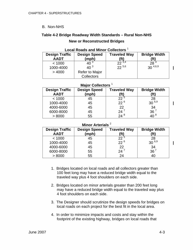
B. Non-NHS
Table 4-2 Bridge Roadway Width Standards – Rural Non-NHS New or Reconstructed Bridges
Local Roads and Minor Collectors 1
Design Traffic AADT
Design Speed (mph)
Traveled Way (ft)
Bridge Width (ft)
< 1000 1000-4000
> 4000
40 3 40 3
Refer to Major Collectors
22 3,4
22 5,628 4
30 4,6,9
|
Major Collectors 1
Design Traffic AADT
Design Speed (mph)
Traveled Way (ft)
Bridge Width (ft)
< 1000 1000-4000 4000-6000 6000-8000
> 8000
45 45 45 45 55
22 5
22 6
22 24 7
24 8
28 30 6,9
34 36 740 8
|
Minor Arterials 2
Design Traffic AADT
Design Speed (mph)
Traveled Way (ft)
Bridge Width (ft)
< 1000 1000-4000 4000-6000 6000-8000
> 8000
45 45 45 55 55
22 5
22 6
22 24 7
24
28 30 6,9
34 36 7
40
|
1. Bridges located on local roads and all collectors greater than 100 feet long may have a reduced bridge width equal to the traveled way plus 4 foot shoulders on each side.
2. Bridges located on minor arterials greater than 200 feet long may have a reduced bridge width equal to the traveled way plus 4 foot shoulders on each side.
3. The Designer should scrutinize the design speeds for bridges on local roads on each project for the best fit in the local area.
4. In order to minimize impacts and costs and stay within the footprint of the existing highway, bridges on local roads that
June 2007 4-3

CHAPTER 4 - SUPERSTRUCTURES
granite bridge curbing, where the face of curb will project 5 inches in front of the face of rail.
||||||||
||||
The need for sidewalks should be considered on a project-by-project basis. Sidewalks should be included on a bridge when there are sidewalks on the approaches, or when it is determined that a sidewalk is warranted. A sidewalk should be included on either one or both sides of a bridge located in or adjacent to village areas or located near pedestrian generators such as neighborhoods, schools, businesses, and commercial development areas. The MaineDOT Bicycle and Pedestrian Coordinator can help determine whether a sidewalk is warranted, based on the criteria for Evaluating Existing or Potential Pedestrian Demand found in the MaineDOT Municipal/Local Cost Sharing Policy. When MaineDOT determines that a sidewalk does not meet Category 1 (fully funded) of the Municipal/Local Cost Sharing Policy, a municipality may request that a sidewalk be provided. In this case, the municipality will be required to pay either 50% or the full cost of providing the sidewalk, in accordance with the criteria outlined in the policy.
||
Sidewalks with projected minimal pedestrian traffic should be 5 feet clear to the face of rail. Sidewalks with projected significant pedestrian traffic should be 6 feet clear to the face of rail. Sidewalk widths for very high pedestrian traffic should be determined on a project-by-project basis. Traffic railings or barriers separating vehicular traffic from pedestrian traffic should be considered only for exceptional cases. Sidewalks with no separation between pedestrian and vehicular traffic will require a combination pedestrian/traffic rail. Wide sidewalks may hinder bridge inspection activities which use the under bridge crane. Bridge Maintenance should be consulted before proposing a sidewalk width greater than 6 feet. Granite bridge curbing may be used only where granite curbing is called for on both approaches. In all other cases, curbs and sidewalks should be entirely concrete with a 1 inch batter of the face of the curb. Concrete for curbs and sidewalks is Class LP.
4.4 Bridge Rail
4.4.1 Definitions
The following definitions are used when selecting a rail system. o Adjusted ADT: ADTcy adjusted for site condition criteria
o ADTcy: average daily traffic for construction year
June 2007 4-8

CHAPTER 4 - SUPERSTRUCTURES
o Kc: adjustment factor for horizontal curvature of alignment (refer to Figure 4-2)
o Kg: adjustment factor for grade (refer to Figure 4-2)
o Ks: adjustment factor for deck height and under structure conditions (refer to Figure 4-3)
June 2007 4-8a

CHAPTER 4 - SUPERSTRUCTURES
Adjusted ADT for which a TL-4 or TL-5 is required Divided or 5 +
lanes Undivided
4 lanes or less One Way
Design Speed (mph)
Percent Trucks
Shoulder
Width (ft)
TL-4 TL-5 TL-4 TL-5 TL-4 TL-5
60
0
0-3 3-7
7-12
3200 3600 4400
*** *** ***
2000 2300 2900
*** *** ***
1600 1800 2200
*** *** ***
5
0-3 3-7
7-12
3000 3300 4100
107300 126300 158400
1900 2100 2700
70300 82800
105600
1500 1700 2100
53700 63200 79200
10
0-3 3-7
7-12
2800 3100 3900
39600 47500 53100
1800 2000 2500
25000 29300 33700
1400 1600 2000
19800 23800 26600
15
0-3 3-7
7-12
2700 2900 3700
24300 29300 31900
1700 1900 2400
15200 17800 20000
1400 1500 1900
12200 14700 16000
20
0-3 3-7
7-12
2500 2800 3500
17500 21100 22800
1600 1800 2200
10900 12800 14300
1300 1400 1800
8800 10600 11400
70
0
0-3 3-7
7-12
2200 2400 2800
191400 379100
***
1300 1500 1700
165000 301500 402400
1100 1200 1400
95700 189600 256400
5
0-3 3-7
7-12
2100 2300 2700
63100 80000 96400
1300 1400 1600
42200 51600 64000
1100 1200 1400
31600 40000 48200
10
0-3 3-7
7-12
2000 2300 2600
32100 38500 42200
1200 1400 1600
20000 22900 26700
1000 1200 1300
16100 19300 21100
15
0-3 3-7
7-12
2000 2200 2600
21500 25300 27000
1200 1300 1600
13100 14700 16900
1000 1100 1300
10800 12700 13500
20
0-3 3-7
7-12
1900 2100 2500
16200 18900 19900
1200 1300 1500
9700 10800 12300
1000 1100 1300
8100 9500 10000
4.4.4 Bicycle Railing
Bicycle bridge rail should be used on any bridge over 20 feet long where there is an established bicycle trail system or where high volumes of bicycle traffic are expected, as determined by the MaineDOT Bicycle and Pedestrian Coordinator.
|||||
The standard height for bicycle bridge rail is 42 inches.
4.4.5 Reduced Standard Bridge Rail
If the bridge is not on the NHS (refer to Figure 2-2), and the adjusted ADT is less than or equal to half of the maximum allowed for a TL-2 system, a rail
June 2007 4-17

CHAPTER 4 - SUPERSTRUCTURES
may be designed rather than crash-tested. The system may be designed in accordance with AASHTO LRFD Section 13 Appendix A for the TL-2 test condition. The railing must also meet all the geometric requirements for its proposed application found in AASHTO LRFD Section 13. Consult with the bridge rail technical resource people for examples of recently designed bridge rails.
4.4.6 Aesthetics
Unfortunately, many of the crash-tested rails are often not considered to be aesthetically pleasing. If a TL-2 rail is appropriate, the Texas Classic Rail may be used when aesthetics is a concern. Consideration should also be given to color-galvanizing steel bridge rail to enhance its appearance. The required specification has been developed, along with specific color recommendations. For bridges satisfying the reduced standard criteria in Section 4.4.5, the Structural Designer may design an alternative attractive rail.
4.4.7 Transitions
For projects on the NHS, transitions from approach rail to bridge rail are required to meet the crash-testing conditions of NCHRP Report 350. The current standard details for transitions are based on the Alaskan Transition, which is 350 approved, with some minor modifications suggested by FHWA.
June 2007 4-18

CHAPTER 4 - SUPERSTRUCTURES
4.6 Wearing Surfaces
4.6.1 General
All bridges should have a 3 inch bituminous wearing surface plus a standard membrane except as follows:
o Bridges on local and collector roads with simple spans and an AADT less than 1000 should use a 1 inch integral concrete wearing surface.
o Bridges with an AADT greater than or equal to 1000 with grades in excess of 4% up to 8% should use a 3 inch bituminous wearing surface with a high performance membrane, a 2 inch unreinforced concrete wearing surface, or a rubberized asphalt wearing surface.
|||
o Bridges with an AADT over 1000 with grades in excess of 8%, or bridges where higher than usual braking or acceleration forces can be expected, such as at stop signs or exit and entrance ramps, should use a 2 inch unreinforced structural concrete wearing surface or a rubberized asphalt wearing surface.
||
4.6.2 Descriptions
The types of wearing surfaces are described below:
4.6.2.1 Bituminous Wearing Surface with Membrane
The wearing surface consists of an impervious waterproofing membrane (nominally 1/4” thick) and approximately 3 inches of bituminous pavement of the grades specified on the plans, and placed in layers of the thickness shown in the Specifications.
4.6.2.2 Unreinforced Structural Concrete Wearing Surface
The wearing surface consists of an unreinforced structural concrete wearing surface with a thickness of 2 inches. The concrete used for the wearing surface is Class LP. The structural concrete wearing surface should be treated with protective coating for concrete surfaces.
4.6.2.3 Integral Concrete Wearing Surface
The wearing surface consists of an extra 1 inch cover over the top of the deck reinforcement for a total concrete cover of 3 inches. The extra inch of concrete should be included in the computations as dead load, but should be excluded from the slab section capacity computations. No allowance is made in the computations for future overlays or wearing surfaces. The concrete used for the slab and wearing surface is Class A. The integral
June 2007 4-20

CHAPTER 4 - SUPERSTRUCTURES
|| || || || || || ||
concrete wearing surface should be treated with protective coating for concrete surfaces.
4.6.2.4 Rubberized Asphalt Wearing Surface
The wearing surface consists of approximately 3 inches of impervious hot mix asphalt with polymer additive placed directly on the concrete surface as specified in the appropriate Special Provision.
4.7 Membranes
Standard waterproofing membrane should be used under bituminous wearing surfaces on most bridge structures. The prequalified list of standard and high performance waterproofing membrane systems can be found on the MaineDOT website at: http://www.maine.gov/mdot/transportation-research/approved-products/waterfroof-membrane-systems.php. Membrane should also be used on concrete buried structures, placed directly on top of the concrete and wrapped down one foot along the vertical wall.
| |
High performance membrane should be used in the following situations:
o Butted precast concrete structures without leveling slabs.
o Major structures with high volumes of traffic where maintenance of traffic issues will result in a difficult wearing surface replacement.
o Wearing surface replacements where a rough surface is anticipated (refer to Section 10.2.2 Wearing Surface Replacement/Rehab).
4.8 Deck Joints and Expansion Devices
4.8.1 General
Deck joints add cost to the structure, increase maintenance requirements, and should be avoided whenever possible. Integral abutments should be used (refer to Section 5.4.2, Integral Abutments) or the slab should be carried over the backwall (refer to Section 6.2.2 Decks) whenever possible. The Designer must become familiar with the Standard Details (520 and 521), as well as applicable manufacturer’s product information, before specifying an expansion device for a particular project. In all other cases, deck joints with appropriate expansion devices will be necessary. The choice of which expansion device to use depends upon the
June 2007 4-21

CHAPTER 4 - SUPERSTRUCTURES
movement rating, which is the magnitude of expected expansion and contraction of the structure due to temperature change. The movement rating is the maximum movement from extreme cold to extreme hot, and is calculated as 1-1/4” per 100 feet of bridge expansion length from a fixed bearing. Compression seals are used for a movement rating up to 2-1/2”. Gland seals are used for a movement rating up to 3 inches. Finger joints are used up to about 12 inches. Extrapolation of finger joint dimensions or modular joints may be used for larger movement ratings.
June 2007 4-21a

CHAPTER 5 - SUBSTRUCTURES
Designers should be aware that this chapter has not yet been updated to reflect the change in policy of designing substructures by AASHTO LRFD, in accordance with Section 3.2.
June 2007 iv

CHAPTER 5 - SUBSTRUCTURES
||||||||||||||||||||||||||
100
150
200
250
300
350
400
450
500
550
600
0' 100' 200' 300'
Bridge Length(feet)
Max
imum
Allo
wab
le P
ile L
oads
(k
ips)
HP14x89-F HP14x73-F HP12x53-F HP10x42-F
330'165'Steel
Concrete 0'
Fy = 36 ksi
100
150
200
250
300
350
400
450
500
550
600
0' 100' 200' 300'
Bridge Length(feet)
Max
imum
Allo
wab
le P
ile L
oads
(kip
s)
HP14x89-P HP14x73-P HP12x53-P HP10x42-P
330'165'
Steel
Concrete 0'
Fy = 36 ksi
Figure 5-5 Maximum Allowable Pile Load For Fixed Head Piles In Dense Sand
Figure 5-6 Maximum Allowable Pile Load For Pinned Head Piles In Dense Sand
June 2007 5-33

CHAPTER 5 - SUBSTRUCTURES
||||||||||||||||||||||||||||
100
200
300
400
500
600
700
800
0' 100' 200' 300'
Bridge Length(feet)
Max
imum
Allo
wab
le P
ile L
oads
(k
ips)
HP14x89-F HP14x73-F HP12x53-F HP10x42-F
330'165'Steel
Concrete 0'
Fy = 50 ksi
100
200
300
400
500
600
700
800
0' 100' 200' 300'
Bridge Length(feet)
Max
imum
Allo
wab
le P
ile L
oads
(k
ips)
HP14x89-P HP14x73-P HP12x53-P HP10x42-P
330'165'Steel
Concrete 0'
Fy = 50 ksi
Figure 5-5a Maximum Allowable Pile Load For Fixed Head Piles In Dense Sand
Figure 5-6a Maximum Allowable Pile Load For Pinned Head Piles In Dense Sand
June 2007 5-33a

CHAPTER 6 - CONCRETE
should increase the rate of corrosion inhibitor to 5.5 gal/yd3. The Structural Designer must verify that the PS&E package contains a Special Provision for this requirement.
6.1.2.2 Prestressing Strand
Prestressing strand should be uncoated low relaxation seven wire strand meeting the requirements of AASHTO M 203 Grade 270. Strands for NEBT structures should typically be 1/2” diameter, with a maximum 0.6” diameter. The standard size of strands for prestressed beam slabs and boxes should typically be 0.6” diameter. Strands for precast deck panels should be a maximum 3/8 inch diameter, while all other strand should be a maximum diameter of 1/2”.
||
Prestressing bars should be uncoated high strength steel bar meeting the requirements of AASHTO M 275.
6.1.2.3 Mild Reinforcement
Refer to Section 6.2.1.2 for reinforcement material requirements for non-prestressed reinforcement.
6.1.3 Economy
6.1.3.1 Release Strength
Concrete strength at release of prestress force can significantly affect cost. Precasters rely on daily use of their prestressing beds. Concrete strength at release is often the controlling factor in the concrete mix design. Excessive release strengths will either force the precaster to use higher strength concrete than the design requires or delay the release of prestressing force. The suggested release strength should be in the range of 4 to 4.5 ksi.
6.1.3.2 Beam Sections
When designing precast superstructures, uniform beam widths and strand patterns should be used whenever possible. Prestressing beds are long and can often accommodate more than one beam. Uniform beam widths and strand patterns allow more than one beam to be placed in the prestressing bed at a time, thus accelerating and economizing production.
June 2007 6-3

CHAPTER 6 - CONCRETE
6.1.4 Design Requirements
6.1.4.1 Concrete Cover
All precast main carrying members should be designed with the stirrups encasing all prestressing strands. The minimum cover for the stirrup is 1 inch from the bottom of the section.
6.1.4.2 Voided Slab and Butted Box Beam Bridges
Transverse Post-Tensioning
Normally, post-tensioning should be accomplished by the use of 0.6” diameter prestressing strand as specified in the applicable Supplemental Specifications. In cases where the chuck-to-chuck length is 25 feet or less, prestressing strand cannot be used due to excessive overstressing for the setting losses. For shorter post-tensioning lengths, the material and final tensile force must be clearly stated on the Plans. The tensile force should be 40k per location. The use of threaded rods such as DYWIDAG bars, is recommended.
|||
DiaphTableparalleover 3considwidenlocateallowa
June 2007
Commentary: The use of 0.6” diameter prestressing strand with a largerpost-tensioning force is intended to limit cracking of the shear keys. Standard Detail 535(02) has been reviewed and approved for use with this larger strand size.
ragms and strand locations should be spaced as described in 6-1. Diaphragms and post-tensioning ducts may be placed l to the centerline of bearing for skews less than 30°. For skews 0°, diaphragms should be placed normal to the beams and eration should be given to torsional loads from sidewalks, future ing, and maintenance of traffic. The end post-tensioning should be d such that it does not interfere with the wingwalls, including nces made for the post-tensioning jack.
6-4

CHAPTER 6 - CONCRETE
Table 6-1 Post Tension and Diaphragm Locations
Beam Type Span Ends 1/3 points
1/4 points
and mid-span
Single mid-
depth strand
Top and
bottom strand
Voided Slabs All X X X
≤ 50 ft X X X Box Beams less than 3 ft
deep > 50 ft X X X
Box Beams 3 ft and deeper All X X X
June 2007 6-4a

CHAPTER 6 - CONCRETE
June 2007 6-6
E. Skew
Voided slab and butted box beam superstructures should not be used for bridges with skew angles greater than 45°. Bridges with heavy skews present problems with beam alignment during erection. Heavy skews also increase shear forces at the obtuse corners that may lead to shear key failure. Utilizing these beams with skews greater than 45° requires the approval of the Engineer of Design. F. Transfer Length |
|||||||||||||
MaineDOT utilizes long solid end diaphragms. The extended length eliminates spatial conflicts between the substructure and the end post-tensioning ducts. However, the solid end section sometimes extends to or beyond the transfer length section location. For such designs, some commercially available software will incorrectly apply the release prestress force to the much smaller voided cross section at the transfer length section location. The consequent error in the axial stress magnitude is much greater than the error in bending stress. Therefore, such software will undervalue the resultant top tensile stress. When the solid end of a voided slab or box beam extends three inches or more beyond the transfer length section location, the Designer should manually analyze the top fiber tensile stress at the transfer length utilizing the solid section.
6.1.4.3 NEBT, AASHTO I-Girder, and Spread Box Beam Bridges
A. Diaphragms
Unless supported by integral abutments, end diaphragms should be designed to allow for jacking during future maintenance operations.
B. Continuity Design
Post-Tensioned Spliced NEBT Girder: The Structural Designer is referred to the PCI guidelines for post-tensioning and splicing NEBTs. Conventionally Reinforced: The design should follow AASHTO LRFD. The Structural Designer is also referred to PCI (1997) as well as Oesterle (1989). Refer to Section 6.1.4.2D for further guidance.

CHAPTER 6 - CONCRETE
June 2007 6-6a
C. Deck Overhang Limits
To control flexural stresses in the top flange of exterior beams, the overhanging portion of the CIP slab as measured from the edge of the top flange should be limited to 2 feet.
6.2 Cast-In-Place Concrete
6.2.1 Materials
6.2.1.1 Concrete
A. Concrete Class
There are four classes of concrete used for cast-in-place (CIP) structures: Class A, Class LP, Class S, and Class Fill. Guidelines on when to use each class are described in Table 6-2. Refer to Standard Specification Section 502 – Structural Concrete for further guidance.

CHAPTER 7 - STEEL
June 2007 7-9
7.2.7 Field Splices
Bolted field splices should be designed as slip-critical. Uncoated weathering steel should be designed for Class B (slip coefficient 0.55) faying surfaces. For painted surfaces, refer to the approved coating list for the appropriate slip coefficient. The Structural Designer should not indicate the thickness of filler plates for splices on the plans. Allowable construction tolerances may affect these thicknesses, which are easily adjusted by the fabricator. |
|||||||||
The splice design should provide adequate clearance to apply an impact wrench to any of the fasteners in the web or flanges; in other words, the extreme rows of bolts in the web should have a clear distance from the flange bolt assemblies. AASHTO and NSBA documents provide minimum bolt hole to edge distances in splice plates and associated components. It is an advantageous design to provide a distance of 1-3/4 inches from the center of a bolt hole to a plate edge and a distance of 4 inches between rows of bolts straddling the girder field splice. This provides fabricators with a tolerance that is manageable for minimal extra cost and is within code guidelines for a 7/8” diameter bolt.
7.3 Economy
The Structural Designer should keep in mind that a design utilizing the least material is not necessarily the most economical design, since material cost represents only about one third of the total fabricated cost of a welded girder. The bulk of the cost lies in fabrication, shop fit-up, delivery, and field erection. Simplification and repetition of details, reduction of fabrication and welding operations, and ease of handling and erection are often better means to achieve cost savings. As a general rule, unstiffened webs should be used for depths of 50 inches and below. For web depths over 50 inches, unstiffened or partially stiffened webs should be used. To determine an optimum number of intermediate stiffeners for a partially stiffened web, a cost of $150 to $200 per stiffener can be assumed. At least 800 pounds of flange material must be saved to justify the introduction of a shop flange splice. Normally, the most economical design results when the flange sizes are carried through the entire positive moment section. It may or may not be cost effective to transition flange sizes in the negative moment section. If a flange transition is specified, the thickness and not the width should be varied, since a uniform flange width allows welding of an entire slab of steel rather than individual pieces.
CHAPTER 7 - STEEL
June 2007 7-9a
The number of beams used in a structure should be determined by taking into account the following:
o Traffic may need to be maintained over the structure during a future redecking. The number and spacing of the beams should allow for future staged construction of a new deck.
o No structure should have less than four beams.
o The maximum beam spacing is limited to 15 feet.
o A cost comparison should be done between the different numbers of beams under consideration, using the procedure discussed in Section 2.2.7 Cost Comparison for Number of Beams. Included in the cost analysis should be any increase
|
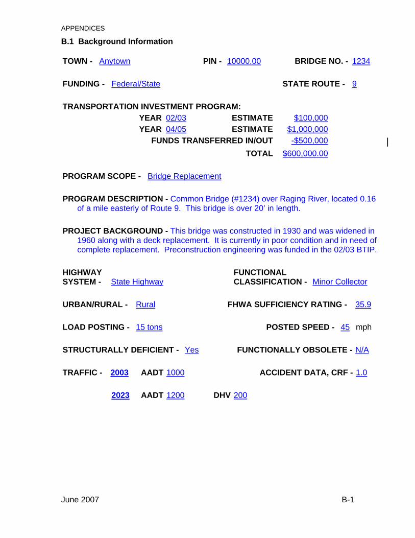
APPENDICES
B.1 Background Information TOWN - Anytown PIN - 10000.00 BRIDGE NO. - 1234 FUNDING - Federal/State STATE ROUTE - 9 TRANSPORTATION INVESTMENT PROGRAM: YEAR 02/03 ESTIMATE $100,000 YEAR 04/05 ESTIMATE $1,000,000
FUNDS TRANSFERRED IN/OUT -$500,000 | TOTAL $600,000.00 PROGRAM SCOPE - Bridge Replacement PROGRAM DESCRIPTION - Common Bridge (#1234) over Raging River, located 0.16
of a mile easterly of Route 9. This bridge is over 20’ in length. PROJECT BACKGROUND - This bridge was constructed in 1930 and was widened in
1960 along with a deck replacement. It is currently in poor condition and in need of complete replacement. Preconstruction engineering was funded in the 02/03 BTIP.
HIGHWAY SYSTEM - State Highway
FUNCTIONAL CLASSIFICATION - Minor Collector
URBAN/RURAL - Rural FHWA SUFFICIENCY RATING - 35.9 LOAD POSTING - 15 tons POSTED SPEED - 45 mph STRUCTURALLY DEFICIENT - Yes FUNCTIONALLY OBSOLETE - N/A TRAFFIC - 2003 AADT 1000 ACCIDENT DATA, CRF - 1.0
2023 AADT 1200 DHV 200
June 2007 B-1

APPENDICES
TOWN - Anytown BRIDGE - Common Bridge ADDITIONAL DESIGN FEATURES - Begin transition @ STA 100+00, begin project @
STA 100+50, end project @ STA 800+50, end transition @ STA 900+00. A 3’ tall garden retaining wall will be constructed between STA 200+00 and 200+25 on the north side.
MAINTENANCE OF TRAFFIC - Maintain two-way traffic on a one-lane temporary bridge
located on the upstream side. CONSTRUCTION SCHEDULE - One construction season with landscaping the following
spring. ADVERTISING DATE - January 2004 PROGRAM FUNDING LEVEL – C Program
AmountTotal
Available Funding
Total
Project Need
Future Program
Need
| | |
Preliminary Engineering = $75,000 $75,000 $125,000 $50,000 | Right-of-Way = $5,000 $5,000 $15,000 $10,000 | STRUCTURE = $700,000 $700,000 | Construction [ APPROACHES =
$0 $0$150,000 $150,000 |
Construction Engineering = $0 $0 $120,000 $120,000 | Total = $80,000 $80,000
$1,110,000 $1,030,000 |
PROJECT FISCALLY APPROVED DATE
ADDITIONAL SOILS INFO. REQUIRED? NoUTILITIES - Verizon, Anytown Sewer, Anytown Water, State Cable, CMP
ADDITIONAL FIELD SURVEY REQUIRED? No
EXCEPTIONS TO STANDARDS - Bridge width is less than State Standards in order to
match existing corridor width. COMMENTS BY ENGINEER OF DESIGN -
June 2007 B-3

APPENDICES
B.3 Recommendation Overpass and Railroad Crossing TOWN - Anytown BRIDGE - Common Bridge BRIDGE NO. - 1234DESIGNED BY - ABC DATE - 3/1/03 PIN - 10000.00APPROVED BY - DATE - PROJECT - Bridge replacement with 800’ of approaches, including transitions. ALIGNMENT DESCRIPTION - Tangent on bridge with two 1000’ horizontal curves
located on each end of the project to match into existing curves. A 600’ crest vertical curve with a finished grade about 4.5’ higher than the existing bridge. New centerline located approximately 4.5’ south of existing bridge centerline.
APPROACH SECTION - Two 11’ lanes with 4’ shoulders. 1:2 sideslopes with standard
steel guardrail and 1:3 sideslopes without guardrail. SPANS - 35’ SKEW - 30 º ahead on left LOADING - HL-93 modified for Strength 1 DESIGN SPEED - 45 mph SUPERSTRUCTURE - Precast, prestressed concrete voided slabs with a non-
composite leveling slab and a 3” bituminous wearing surface on ¼” membrane waterproofing. 30’ curb-to-curb with standard 2-bar steel rail and a 2% normal crown. Install snow fence behind bridge rail on both sides of the bridge.
||
ABUTMENTS - Cantilevered concrete abutments on H-piles driven to ledge. PIERS - N/A CLEARANCES - EXISTING PROPOSED VERTICAL - 16.25 FT 22.5 FT HORIZONTAL - 20 FT 30 FT DISPOSITION OF EXISTING BRIDGE - Existing structure to be removed in its entirety,
and to become property of the Contractor. AVAILABLE SOILS INFORMATION - Existing plans and preliminary borings show
ledge to be present at about 30’-50’ below ground. For more information, please refer to the Geotechnical Report.
June 2007 B-4

APPENDICES
TOWN - Anytown BRIDGE - Common Bridge ADDITIONAL DESIGN FEATURES – Begin transition @ STA 100+00, begin project @
STA 100+50, end project @ STA 800+50, end transition @ STA 900+00. A 3’ tall garden retaining wall will be constructed between STA 200+00 and 200+25 on the north side.
MAINTENANCE OF TRAFFIC - Maintain two-way traffic on existing bridge with stage
construction. CONSTRUCTION SCHEDULE - One construction season with landscaping the
following spring. ADVERTISING DATE - January 2004 PROGRAM FUNDING LEVEL – C Program
AmountTotal
Available Funding
Total
Project Need
Future Program
Need
| | |
Preliminary Engineering = $70,000 $70,000 $70,000 $0 | Right-of-Way = $5,000 $5,000 $10,000 $5,000 | STRUCTURE = $300,000 $300,000 | Construction [ APPROACHES =
$0 $0$100,000 $100,000 |
Construction Engineering = $0 $0 $70,000 $70,000 | Total = $75,000 $75,000
$550,000 $475,000 |
PROJECT FISCALLY APPROVED DATE
ADDITIONAL SOILS INFO. REQUIRED? NoUTILITIES - Verizon, Anytown Sewer, Anytown Water, State Cable, CMP
ADDITIONAL FIELD SURVEY REQUIRED? No
EXCEPTIONS TO STANDARDS - Bridge width is less than State Standards in order to
match existing corridor width. COMMENTS BY ENGINEER OF DESIGN -
June 2007 B-5

APPENDICES
TOWN - Anytown BRIDGE - Common Bridge ADDITIONAL DESIGN FEATURES - Begin transition @ STA 100+00, begin project @
STA 100+25, end project @ STA 400+25, end transition @ STA 400+50.
MAINTENANCE OF TRAFFIC - Maintain two-way traffic with stage construction and
temporary traffic signals. CONSTRUCTION SCHEDULE - One construction season. ADVERTISING DATE - January 2004 PROGRAM FUNDING LEVEL – Construction Program
AmountTotal
Available Funding
Total
Project Need
Future Program
Need
| | |
Preliminary Engineering = $120,000 $120,000 $120,000 $0 | Right-of-Way = $10,000 $10,000 $10,000 $0 | STRUCTURE = $700,000 $0 | Construction [ APPROACHES =
$850,000 $850,000$150,000 $0 |
Construction Engineering = $120,000 $120,000 $120,000 $0 | Total = $1,100,000 $1,100,000
$1,100,000 $ 0 |
PROJECT FISCALLY APPROVED DATE
ADDITIONAL SOILS INFO. REQUIRED? NoUTILITIES - Verizon, Anytown Sewer, Anytown Water, State Cable, CMP
ADDITIONAL FIELD SURVEY REQUIRED? No
EXCEPTIONS TO STANDARDS - N/A COMMENTS BY ENGINEER OF DESIGN -
June 2007 B-7

APPENDICES
TOWN - Anytown BRIDGE - Common Bridge ADDITIONAL DESIGN FEATURES - Begin transition @ STA 100+00, begin project @
STA 100+50, end project @ STA 300+50, end transition @ STA 400+00.
MAINTENANCE OF TRAFFIC - Close bridge to traffic for 5 days and detour traffic onto
This Road, That Street, and Route 1. Total length of detour is 7.5 miles. CONSTRUCTION SCHEDULE - One construction season. Bridge must be reopened to
traffic by Labor Day. ADVERTISING DATE - January 2004 PROGRAM FUNDING LEVEL -Construction Program
AmountTotal
Available Funding
Total
Project Need
Future Program
Need
| | |
Preliminary Engineering = $35,000 $35,000 $35,000 $0 | Right-of-Way = $5,000 $5,000 $5,000 $0 | STRUCTURE = $240,000 $0 | Construction [ APPROACHES =
$275,000 $275,000$35,000 $0 |
Construction Engineering = $35,000 $35,000 $35,000 $0 | Total = $350,000 $350,000
$350,000 $ 0 |
PROJECT FISCALLY APPROVED DATE
ADDITIONAL SOILS INFO. REQUIRED? NoUTILITIES - Verizon, Anytown Sewer, Anytown Water, State Cable, CMP
ADDITIONAL FIELD SURVEY REQUIRED? No
EXCEPTIONS TO STANDARDS - Recommended bridge width is less than State
Standards in order to match existing corridor width. Reduced berm offset is recommended to minimize wetland impacts.
COMMENTS BY ENGINEER OF DESIGN -
June 2007 B-9

APPENDICES
TOWN - Anytown BRIDGE - Common Bridge ADDITIONAL DESIGN FEATURES - Begin transition @ STA 100+00, begin project @
STA 100+50, end project @ STA 300+50, end transition @ STA 400+00.
MAINTENANCE OF TRAFFIC - Close bridge to traffic for 5 days and detour traffic onto
This Road, That Street, and Route 1. Total length of detour is 7.5 miles. CONSTRUCTION SCHEDULE - One construction season. Bridge must be reopened to
traffic by Labor Day. ADVERTISING DATE - January 2004 PROGRAM FUNDING LEVEL -Construction Program
AmountTotal
Available Funding
Total
Project Need
Future Program
Need
| | |
Preliminary Engineering = $30,000 $30,000 $30,000 $0 | Right-of-Way = $5,000 $5,000 $5,000 $0 | STRUCTURE = $200,000 $0 | Construction [ APPROACHES =
$235,000 $235,000$35,000 $0 |
Construction Engineering = $30,000 $30,000 $30,000 $0 | Total = $300,000 $300,000
$300,000 $ 0 |
PROJECT FISCALLY APPROVED DATE
ADDITIONAL SOILS INFO. REQUIRED? NoUTILITIES - Verizon, Anytown Sewer, Anytown Water, State Cable, CMP
ADDITIONAL FIELD SURVEY REQUIRED? No
EXCEPTIONS TO STANDARDS - Recommended bridge width is less than State
Standards in order to match existing corridor width. Reduced berm offset is recommended to minimize wetland impacts.
COMMENTS BY ENGINEER OF DESIGN -
June 2007 B-11

APPENDICES
June 2007 B-16
B.11 “Shortform” Preliminary Design Report TOWN - Anytown BRIDGE - Common Bridge PIN - 10000.00DESIGNED BY - ABC DATE - 3/1/04 BRIDGE NO. - 1234APPROVED BY - DATE - STATE ROUTE - 9
PROGRAM SCOPE - Bridge Wearing Surface Replacement
PROGRAM DESCRIPTION – Replacement of deficient wearing surface on Common Bridge (#1234) over Raging River, located 0.16 of a mile easterly of Route 9. This bridge is over 20’ in length.
PROJECT RECOMMENDATION - Place 3” bituminous wearing surface on ¼” membrane waterproofing, rehabilitating existing concrete deck as needed. Modify existing expansion joints to accommodate thicker wearing surface and replace seals. Replace two broken bridge rail posts.
BRIDGE ROADWAY SECTION - Two 11’ lanes with 4’ shoulders for a total curb-to-curb width of 30’.
SPANS - 80’-140’-80’ SKEW - 30 º ahead on left
HIGHWAY SYSTEM - State Highway
FUNCTIONAL CLASSIFICATION - Minor Collector - Rural
TRAFFIC - 2003 AADT 1000 ACCIDENT DATA, CRF - 1.0
2023 AADT 1200 DHV 200 POSTED SPEED - 45 mph
UTILITIES - Verizon, Anytown Sewer, Anytown Water, State Cable, CMP
EXCEPTIONS TO STANDARDS - N/A
MAINTENANCE OF TRAFFIC AND CONSTRUCTION SCHEDULE- Maintain two-way traffic with staged construction and temporary traffic signals for one construction season.
BTIP – 04/05 ADVERTISING DATE – Sep. 2004
Program Amount
Total Available Funding
Total
Project Need
Future Program
Need
| | |
Preliminary Engineering = $120,000 $120,000 $120,000 $0 |Right-of-Way = $10,000 $10,000 $10,000 $0 |STRUCTURE = $700,000 $0 |Construction [ APPROACHES =
$850,000 $850,000$150,000 $0 |
Construction Engineering = $120,000 $120,000 $120,000 $0 |Total = $1,100,000 $1,100,000
$1,100,000 $ 0 |
PROJECT FISCALLY APPROVED DATE
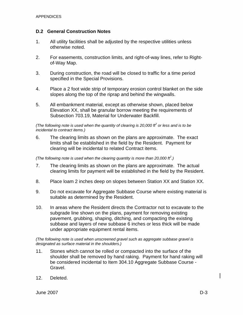
APPENDICES
D.2 General Construction Notes
1. All utility facilities shall be adjusted by the respective utilities unless otherwise noted.
2. For easements, construction limits, and right-of-way lines, refer to Right-of-Way Map.
3. During construction, the road will be closed to traffic for a time period specified in the Special Provisions.
4. Place a 2 foot wide strip of temporary erosion control blanket on the side slopes along the top of the riprap and behind the wingwalls.
5. All embankment material, except as otherwise shown, placed below Elevation XX, shall be granular borrow meeting the requirements of Subsection 703.19, Material for Underwater Backfill.
(The following note is used when the quantity of clearing is 20,000 ft2 or less and is to be incidental to contract items.)
6. The clearing limits as shown on the plans are approximate. The exact limits shall be established in the field by the Resident. Payment for clearing will be incidental to related Contract items.
(The following note is used when the clearing quantity is more than 20,000 ft2.)
7. The clearing limits as shown on the plans are approximate. The actual clearing limits for payment will be established in the field by the Resident.
8. Place loam 2 inches deep on slopes between Station XX and Station XX.
9. Do not excavate for Aggregate Subbase Course where existing material is suitable as determined by the Resident.
10. In areas where the Resident directs the Contractor not to excavate to the subgrade line shown on the plans, payment for removing existing pavement, grubbing, shaping, ditching, and compacting the existing subbase and layers of new subbase 6 inches or less thick will be made under appropriate equipment rental items.
(The following note is used when unscreened gravel such as aggregate subbase gravel is designated as surface material in the shoulders.)
11. Stones which cannot be rolled or compacted into the surface of the shoulder shall be removed by hand raking. Payment for hand raking will be considered incidental to Item 304.10 Aggregate Subbase Course - Gravel.
|12. Deleted.
June 2007 D-3

APPENDICES
13. Modified eccentric loader terminals shall be installed concurrently with the placement of each section of beam guardrail.
||||
(The following note regarding Cable Guardrail is no longer used and has been deleted.)
14. Deleted.
15. Extended-use erosion control blanket, seeded gutters, riprap downspouts, and other gutters lined with stone ditch protection shall be constructed after paving and shoulder work is completed, where it is apparent that runoff will cause continual erosion. Payment will be made under appropriate Contract items.
(The following note is used for Reduced Berm Offsets.) 16. Guardrail post length and embedment as shown in the Standard Details
shall be modified from the indicated 6 foot length to 7 feet, with 4’-6” of embedment.
17. Protective coating for concrete surfaces shall be applied to the following areas:
All exposed surfaces of concrete curbs and sidewalks, Fascia down to drip notch, All exposed surfaces of concrete transition barriers, Concrete wearing surfaces, Concrete barrier railing, Top of abutment backwalls and to one foot below the top of
backwalls on the back side. ||||
18. Erosion Control Mix may be substituted in those areas normally receiving loam and seed as directed by the Resident. Placement shall be in accordance with Standard Specification 619 Mulch. Payment will be made under Item 619.1401 Erosion Control Mix.
(The following two notes are used in conjunction with Standard Detail 610(2-4).) 19. Place riprap on sideslopes up to elevation XX.
20. Construct the riprap shelf at each abutment at elevation XX.
||||
(The following five notes are used as needed.) 21. Bidders and Contractors may obtain a copy of the existing bridge plans by
contacting the Project Manager. The plans are reproductions of the original drawings as prepared for the construction of the bridge. It is very
June 2007 D-4

APPENDICES
D.8 Standard Notes Precast Concrete Superstructures
(The following note is used with 0.5 inch diameter strand.) 1. Prestressing Strands shall be 0.5 inch diameter. The tensioning force is 31
kips per prestressing strand.
(The following note is used with 0.6 inch diameter strand.) 2. Prestressing strands shall be 0.6 inch diameter. The tensioning force is 44
kips per prestressing strand.
3. The top surface of the upper flange of the prestressed beams shall be raked to a surface roughness of plus or minus 1/4”, except at locations corresponding to the blocking points. At these locations a flattened area of sufficient size shall be left to facilitate taking elevations for setting bottom of slab elevations.
4. The drilling of holes in the prestressed beams and the use of power-actuated tools on the beams will not be permitted.
5. Neoprene pads shall be either polychloroprene or natural polyisoprene of 50±5 Shore A durometer hardness, and shall conform to the requirements of Division 2, Section 18.2 of AASHTO Standard Specifications for Highway Bridges. Neoprene pads will not be paid for directly, but will be considered incidental to related Contract items.
6. Install a 1 inch diameter nonmetallic void drain in the bottom of each void at both ends.
7. Reinforcing steel shall have 2 inches minimum cover unless otherwise noted.
8. Post-tensioning strands shall be covered by a seamless polypropylene sheath, with corrosion inhibiting grease between the strands and sheath, for the full length of the strand except at the anchorage location.
9. The Contractor shall calibrate the jacking equipment as necessary to provide an anchorage of 38 to 41 kips after setting losses in each 0.6” diameter post-tensioning strand.
(The following note is used for all voided slab and butted box beam structures.)
10. Screed rails shall be installed to the elevation shown on the profile, adjusted for wearing course thickness and cross slope.
June 2007 D-12