Embed Size (px)
Citation preview

NASA Technical Paper 2857
1 1988
I National Aeronautics I and Space Administration
I Scientific and Technical Information Division
Development and Flight Test Experiences With a Flight-Crucial Digital Control System
Dale A. Mackall Ames Research Center Dryden Flight Research Facility Edwards, Calgornia
https://ntrs.nasa.gov/search.jsp?R=19890014956 2018-07-16T04:19:47+00:00Z

I CONTENTS Page
~ SUMMARY . . . . . . . . . . . . . . . . . . . . . . . . . . . . . . . . . . . I
1
1 INTRODUCTION . . . . . 1
2 NOMENCLATURE . . 2
3 SYSTEM SPECIFICATION . . 5 3.1 Con t ro l Laws and Handling Q u a l i t i e s . . . . . . . . . . . . . . . . . 5 3.2 R e l i a b i l i t y and F a u l t Tolerance . . . . . . . . . . . . . . . . . . . 5
4 DESIGN . . . . . . . . . . . . . . . . . . . . . . . . . . . . . . . . . . 6 4.1 System A r c h i t e c t u r e and F a u l t Tolerance . . . . . . . . . . . . . . . 6
4.1.1 D i g i t a l f l i g h t c o n t r o l system a r c h i t e c t u r e . . . . . . . . . . 6 4.1.2 D i g i t a l f l i g h t c o n t r o l system computer hardware . . . . . . . . 8 4.1.3 Avionics i n t e r f a c e . . . . . . . . . . . . . . . . . . . . . . 8 4.1.4 P i l o t i n t e r f a c e . . . . . . . . . . . . . . . . . . . . . . . . 9 4.1.5 Actua tor i n t e r f a c e . . . . . . . . . . . . . . . . . . . . . . 10 4.1.6 Electr ical sys tem i n t e r f a c e . . . . . . . . . . . . . . . . . . 11 4.1.7 Selector monitor and f a i l u r e manager . . . . . . . . . . . . . 12 4.1.8 B u i l t - i n t es t and memory mode . . . . . . . . . . . . . . . . . 14
4.2 C o n t r o l L a w s . . . . . . . . . . . . . . . . . . . . . . . . . . . . . 15 4.2.1 C o n t r o l l a w development process . . . . . . . . . . . . . . . . 15 4.2.2 Con t ro l l a w des ign . . . . . . . . . . . . . . . . . . . . . . 15
4.3 D i g i t a l F l i g h t Con t ro l System Software . . . . . . . . . . . . . . . . 17 4.3.1 Software development process . . . . . . . . . . . . . . . . . 18 4.3.2 Software des ign . . . . . . . . . . . . . . . . . . . . . . . . 19
5 SYSTEM-SOFTWARE QUALIFICATION AND DESIGN ITERATIONS . . . . . . . . . . . . 19 5.1 Schedule . . . . . . . . . . . . . . . . 5.2 Software V e r i f i c a t i o n . . . . . . . . .
5.2.1 V e r i f i c a t i o n t es t p l a n . . . . . 5.2.2 V e r i f i c a t i o n suppor t equipment . 5.2.3 V e r i f i c a t i o n tests . . . . . . . 5.2.4 Reve r i fy ing t h e des ign i t e r a t i o n s
5.3 System V a l i d a t i o n . . . . . . . . . . . 5.3.1 V a l i d a t i o n tes t p l a n . . . 5.3.2 Support equipment . . . . . . . . 5.3.3 V a l i d a t i o n tests . . . . . . . . 5.3.4 Reva l ida t ion of des igns . . . . .
5.4 Q u a l i f i c a t i o n I s s u e s . . . . . . . . . .
. . . . . . . . . . . . . . . . . . . . . . . . . . . . . . . . . . . . . . . . . . . . . . . . . . . . . . . . . . . . . . . . . . . . . . . . . . . . . . . . . . . . . . . . . . . . . . . . . . . . . . . . . . . . . . . . . . . . . . . . . . . . . . . . . . . . . . . . . . . . . . . . . . . . . . . . . . . . . . . . . . . . . . . . . . . . . . . . . . . . .
20 21 21 22 22 24 24 24 25 25 33 33
6 CONFIGURATION CONTROL . 33
1 7 FLIGHTTEST . . . . . . . . . . . . . . . . . . . . . . . . . . . . . . . . 34
7.2.1 I n - f l i g h t expe r i ence . . . . . . . . . . . . . . . . . . . . . 37 7.2.2 Ground exper ience . . . . . . . . . . . . . . . . . . . . . . . 39 7.2.3 Summary . . . . . . . . . . . . . . . . . . . . . . . . . . . . 40
35 I 7.1 Genera l . . . . . . . . . . . . . . . . . . . . . . . . . . . . . . . 1 7.2 Faul t -Toleran t Design . . . . . . . . . . . . . . . . . . . . . . . . 37
I 7.3 Con t ro l Laws . . . . . . . . . . . . . . . . . . . . . . . . . . . . . 41
I
I iii
i PRECEDING PAGE BLANK NOT FILMED

7.4 Hardware . . . . . . . . . . . . . . . . . . . . . . . . . . . . . . . 42 7.5 Software . . . . . . . . . . . . . . . . . . . . . . . . . . . . . . . 43
8 OBSERVATIONS AND RECOMMENDATIONS . 44 8.1 Anomaly of Flight 44, A Case Study . . . . . . . . . . . . . . . . . . 44
8.1.1 Specifcation . . . . . . . . . . . . . . . . . . . . . . . . . 44 8.1.2 Design . . . . . . . . . . . . . . . . . . . . . . . . . . . . 45 8.1.3 Qualification . . . . . . . . . . . . . . . . . . . . . . . . . 45
development Phase . . . . . . . . . . . . . . . . . . . . . . . . . . 45 8.2.1 Specification . . . . . . . . . . . . . . . . . . . . . . . . . 45 8.2.2 Design . . . . . . . . . . . . . . . . . . . . . . . . . . . . 46 8.2.3 Qualification . . . . . . . . . . . . . . . . . . . . . . . . . 47 8.2.4 Flight test . . . . . . . . . . . . . . . . . . . . . . . . . . 48
8.2 Observations and Recommendations by
9 CONCLUDINGREMARKS . 49
APPENDIX -CONTROL LAW VERIFICATION REQUIREMENTS 50
iv

SUMMARY 1 INTRODUCTION
Engineers and s c i e n t i s t s i n t h e advanced f i g h t e r technology i n t e g r a t i o n (AFTI) F-16 program i n v e s t i g a t e d t h e i n t e g r a - t i o n of emerging t echno log ie s i n t o an advanced f i g h t e r a i r c r a f t . AFTI'S t h r e e major technologies inc luded ( 1 ) f l i g h t - c r u c i a l d i g i t a l c o n t r o l , (2) decoupled a i r c r a f t f l i g h t c o n t r o l , and ( 3 ) i n t e - g r a t i o n of av ion ic s , f l i g h t c o n t r o l , and p i l o t d i sp lays . I n a d d i t i o n t o i n v e s t i - g a t i n g improvements i n f i g h t e r perform- ance, r e s e a r c h e r s s t u d i e d t h e g e n e r i c problems conf ron t ing t h e d e s i g n e r s of h i g h l y i n t e g r a t e d f l i g h t - c r u c i a l d i g i t a l c o n t r o l systems.
The au tho r provides an overview of bo th t h e advantages and problems of in - t e g r a t e d d i g i t a l c o n t r o l systems. An examinat ion of t h e s p e c i f i c a t i o n , de- s i g n , q u a l i f i c a t i o n , and f l i g h t t e s t l i f e - c y c l e phase is provided. An over- view is g iven of t h e f a u l t - t o l e r a n t des ign , multimoded decoupled f l i g h t c o n t r o l l a w s , and i n t e g r a t e d a v i o n i c s des ign . The approach to q u a l i f y i n g t h e so f tware and system des igns is d i scussed , and t h e e f f e c t s of des ign choices on system q u a l i f i c a t i o n are h igh l igh ted .
AFTI F-16 f l i g h t tes t r e s u l t s are summarized f o r t h e f a u l t - t o l e r a n t , de- coupled f l i g h t c o n t r o l , hardware, and so f tware requirements . The effects of d e s i g n choices and q u a l i f i c a t i o n proce- d u r e s on f l i g h t tes t ope ra t ions are de- t a i l e d , based on AFTI f l i g h t experience.
Observat ions and recommendations are g iven f o r each development phase - speci- f i c a t i o n , des ign , q u a l i f i c a t i o n , and f l i g h t test.
The advanced f i g h t e r technology i n t e g r a - t i o n (AFT11 F-16 program provided t h e oppor tun i ty t o i n v e s t i g a t e t h e bene- f i t s and complex i t i e s of i n t e g r a t i n g advanced a i r c r a f t t echno log ie s i n t o a f i g h t e r aircraft. The s tudy w a s a j o i n t Nat iona l Aeronaut ics and Space Adminis t ra t ion ( N A S A ) , U.S. A i r Force, and U.S. Navy program and w a s managed by t h e A i r Force F l i g h t Dynamics Labo- r a t o r y . NASA g o a l s were to ensu re s a f e t y du r ing f l i g h t t e s t i n g and to p rov ide an independent assessment of t h e advanced technologies .
The pr imary s u b j e c t of t h i s r e p o r t i s the d i g i t a l f l i g h t c o n t r o l system (DFCS) and i t s i n t e g r a t i o n wi th t h e a v i o n i c s and p i l o t d i sp l ays . A n i n t r o - d u c t i o n t o t h e h i s t o r y , r a t i o n a l e , and nomenclature of d i g i t a l f l i g h t c o n t r o l systems can be found i n S z a l a i (1978) . The AFTI F-16 DFCS development objec- t i v e s inc luded assessment of a t r i p l e x d u a l - f a i l o p e r a t e a r c h i t e c t u r e , i n t e g r a - t i o n of a v i o n i c s and p i l o t d i s p l a y s with t h e DFCS, and development of mission- s p e c i f i c decoupled f l i g h t c o n t r o l modes.
Opera t ing a DFCS wi thou t miss ion impairment a f t e r any two f a i l u r e s r equ i r ed a minimum of f o u r channels of redundancy i n p r e v i o u s l y designed sys- t e m s . I f a t r i p l e x system could cor- r e c t l y choose between t h e remaining two channels when the second f a i l u r e occurred , a c q u i s i t i o n and maintenance costs f o r t h e f l i g h t c o n t r o l system could be reduced. Reducing p i l o t work- load and i n c r e a s i n g weapon e f f e c t i v e n e s s were t h e goa l s of i n t e g r a t i n g t h e DFCS and i t s mis s ion - spec i f i c decoupled con- t r o l modes wi th the a v i o n i c s system and
p i l o t d i sp l ays . In p r e v i o u s l y des igned systems, t h e f l i g h t c o n t r o l s d i d n o t have s p e c i f i c modes f o r t h e d i f f e r e n t missions. The p i l o t w a s r e q u i r e d t o i n d i v i d u a l l y conf igu re each a v i o n i c system f o r a mission.
Th i s report i n c l u d e s an h i s t o r i c a l review of t h e development and f l i g h t t e s t of t h i s i n t e g r a t e d DFCS program. The h i s t o r i c a l review i s s t r u c t u r e d t o p rov ide an adequate background of t h e development p rocess and the r e s u l t i n g des ign needed t o comprehend t h e f l i g h t t e s t r e s u l t s . The a u t h o r addres ses each of t h e development phases - s p e c i f i c a - t i o n , des ign , q u a l i f i c a t i o n , and f l i g h t test . Impor tan t l e s s o n s l ea rned are i l l u s t r a t e d wi th examples from f l i g h t tes t experience.
The i n c r e a s i n g use of system i n t e g r a t i o n to i n c r e a s e a i r c r a f t performance, and t h e f l i g h t c ruc ia l n a t u r e of t h e s e systems, d i c t a t e s a thorough assessment of t h i s i n t e - g r a t e d DFCS program.
2 NOMENCLATURE
AAG a i r - t o - a i r gunnery
ACK acknowledge
A-D ana log to d i g 1 t a l
AD I a t ti tude d i r e c t i o n a l i n d i c a t o r
AFT1 advanced f i g h t e r tech- nology i n t e g r a t i o n
AGL above ground l e v e l , f t
A I U a c t u a t o r i n t e r f a c e u n i t
ALT alt imeter
AMUX a v i o n i c s mul t ip l ex bus
A/S
ASB
ASG
ATP
AY
ac
a lpha
an
B I T
b e t a
CADC
ccv
CHGR
CPC
CPDS
CPPS
CPU
c.g.
D-A
DAAG
DASB
DASG
DFCS
a i r s p e e d
a i r - t o - s u r f a c e bombing
a i r - t o - s u r f a c e gunnery
acceptance t e s t procedure
l a t e ra l a c c e l e r a t i o n , f t / s e c 2
a l t e r n a t i n g c u r r e n t
a n g l e of a t t a c k , deg
normal a c c e l e r a t i o n , f t / s e c 2
b u i l t - i n test
a n g l e of s i d e s l i p , deg
c e n t r a l a i r d a t a computer
c o n t r o l conf igured v e h i c l e
cha rge r , b a t t e r y
computer program component
computer program development s p e c i f i c a t i o n
computer program p roduc t s p e c i f i c a t i o n ~
i c e n t r a l p r o c e s s i n g u n i t
c e n t e r of g r a v i t y , pe rcen tage (
mean aerodynamic chord I
i d i g i t a l t o ana log
I
decoupled a i r - t o - a i r gunnery 1
decoupled a i r - t o - s u r f a c e I bombing I I
I decoupled a i r - t o - s u r f a c e gunnery I
d i g i t a l f l i g h t c o n t r o l system ~
2

DGFT
DN
DNRM
DST
d c
deg/sec
EMIC
EPU
ETSE
FCC
FCR
FDIR
FLCC
FM
FMET
FPME
f l t
f t
dog f i g h t
down
decoupled normal
device s t a t u s table
d i r e c t c u r r e n t
degrees
degrees per second
e l e c t r o m a g n e t i c i n t e r f e r e n c e and c o m p a t i b i l i t y
emergency power u n i t
engineer ing tes t s u p p o r t equipment
f i r e c o n t r o l computers
f i r e c o n t r o l r a d a r
f a u l t d e t e c t i o n , i n d e n t i f i c a - t i o n , and r e c o n f i g u r a t i o n
f l i g h t c o n t r o l computer
f a i l u r e manager, a software component
f a i l u r e modes and e f f e c t s t e s t i n g
f l i g h t p a t h maneuver enhancement
f l i g h t
f e e t
good channel average
G command
l o n g i t u d i n a l acceleration, g
HS I
HUD
HZ
h r
I BU
I FFC
I L S
I N U
I oc
I S A
KCAS
k
LARAP
LAT-DIR
LCND
LEF
L FLP
LH
L HT
LOC
LQS
LRU
l b
M
M A X
h o r i z o n t a l s i t u a t i o n i n d i c a to r
head-up d i s p l a y
h e r t z
hours
independent back-up u n i t
i n t e g r a t e d f l i g h t f i r e c o n t r o l
i n s t r u m e n t landing system
i n e r t i a l n a v i g a t i o n u n i t
input -output c o n t r o l l e r
i n t e g r a t e d s e r v o a c t u a t o r
knots c a l i b r a t e d a i r s p e e d
thousand
low-a l t i tude r a d a r a u t o p i l o t
l a t e r a l - d i r e c t i o n a l
l e f t canard
leading-edge f l ap
l e f t t r a i l i n g edge f l ap
l e f t hand
l e f t h o r i z o n t a l t a i l
l o c a t i o n i n memory
l i n e a r quadratic s y n t h e s i s
l i n e replaceable u n i t
pounds
Mach
maximum a f t e r b u r n e r power
3

MHz
MIL
MPD
MSL
MSOV
msec
NX
NY
N Z
OFP
P
0
P
PDG
PLA
PMG
PRME
PS
P S A
PS
l b / f t 2
Q
Qc
R
RAM
m i 1 l i o n h e r t z
m i l i t a r y p o w e r
multipurpose d i s p l a y
C median select l o g
missile o v e r r i d e
mi l l i s econd
l o n g i t u d i n a l load f a c t o r , g
l a te ra l load f a c t o r , g
normal load f a c t o r , g
o p e r a t i o n a l f l i g h t program
r o l l rate, deg/sec
r o l l a c c e l e r a t i o n , deg/sec2
programmable d i s p l a y g e n e r a t o r
power l e v e r ang le , deg
permanent magnet g e n e r a t o r
p i t c h rate maneuver enhancement
p r e s s u r e s y s t e m
pneumatic s enso r assembly
s ta t ic p r e s s u r e
pounds per squa re f o o t
p i t c h rate, deg/sec
impact p r e s s u r e
yaw rate, deg/sec
random-access memory
RCND
RFLP
RH
RHT
RM
ROM
RUD
r a d
r ad / sec
recon
rPm
SAAG
S A S B
SASG
S / M
S MS
S/N
SNRM
sow
SP
S R
S V 1 , 2 , 3
sec
T
r i g h t canard
r i g h t f l a p
r i g h t hand
r i g h t h o r i z o n t a l t a i l
redundance managment
read on ly memory
rudder
r a d i a n
r a d i a n s per second
r e c o n f i g u r a t i o n
r e v o l u t i o n s per minute
standard air-to-air gunnery
s t anda rd a i r - t o - s u r f a c e bombing
1
s t a n d a r d a i r - t o - s u r f a c e I
I gunnery
selector monitor
s t o r e s management se t
ser ia l number i ! I
s t a n d a r d normal mode
s t a t emen t of work
p i t c h s t i c k
ro l l s t i c k
se rvova lues 1 I 2 I 3
second
t h r o t t l e t w i s t
4

TCO
TEF
TR
V
V and V
VA
v ac
VCRI
V d c
V I D
w
t o t a l computed o u t p u t
t r a i l i n g edge f l a p s , deg
t r ans fo rmer r e c t i f i e r
v e l o c i t y v e c t o r
v e r i f i c a t i o n and v a l i d a t i o n
vo 1 t-amps
v o l t s , ac
v e r i f i c a t i o n c r o s s r e f e r e n c e index
v o l t s , dc
v ideo
f requency , rad/sec
3 SYSTEM SPECIFICATION
I n the system s p e c i f i c a t i o n phase, oper- a t i o n a l requi rements are d e t a i l e d t o a l e v e l t h e d e s i g n e r s can use.
The f i rs t step i n s p e c i f y i n g the AFTI F-16 ( f i g . 1 ) system des ign w a s t h e s t a t e m e n t of work (SOW) released on November 16, 1978 by t h e A i r Force Wright Aeronau t i ca l Labora to r i e s , Wright P a t t e r s o n A i r Force Base, Ohio. Th i s document s p e c i f i e d t h e requi rements f o r decoupled c o n t r o l , weapon l i n e p o i n t i n g , aerodynamic v e h i c l e mod i f i ca t ions , digi- t a l f l i g h t c o n t r o l system, and p i l o t - v e h i c l e i n t e r f a c e . These g e n e r a l requi rements were then d e t a i l e d i n t h e fo l lowing c a t e g o r i e s : a i r v e h i c l e , sys- tems engineer ing , tes t and e v a l u a t i o n . The c o n t r a c t o r , General Dynamics, i n F o r t Worth, Texas, w a s r e s p o n s i b l e f o r t h e second step i n s p e c i f y i n g t h e sys- t e m . A f t e r t h e c o n t r a c t o r gene ra t ed t h e system s p e c i f i c a t i o n , an e n t i r e tree of s p e c i f i c a t i o n s grew f o r each system, new
o r modified, t h a t w a s r e q u i r e d t o accom- p l i s h AFT1 o b j e c t i v e s . The fo l lowing paragraphs i n s e c t i o n 3 w i l l add res s t h e s p e c i f i c a t i o n s on ly as they apply to t h e d i g i t a l f l i g h t c o n t r o l system.
3.1 Con t ro l Laws and Handling Q u a l i t i e s
The SOW s p e c i f i e d the requi rements f o r t h e unique decoupled c o n t r o l modes ( t a b l e 1 1 and t h e a i r f r a m e s t a b i l i t y and f l y i n g q u a l i t i e s requirements. Decoupled c o n t r o l requi rements inc luded d i r e c t l i f t and s i d e f o r c e , f u s e l a g e p o i n t i n g independent of f l i g h t p a t h , ver- t i ca l and la teral t r a n s l a t i o n , and wings l e v e l s t e e r i n g . The s t a b i l i t y and f l y - i n g q u a l i t i e s requi rements were based on MIL-F-8785C (U.S. Department of Defense, 1980). From t h e SOW, t h e c o n t r a c t o r pro- v ided t h e d e t a i l e d requi rements f o r a i r - c r a f t s t a b i l i t y and f l y i n g q u a l i t i e s . Requirements i nc luded shor t -pe r iod damping r a t i o l i m i t s , s ho r t -pe r iod f requency requi rements , du tch r o l l f r e - quency and damping, and f o r c e g r a d i e n t l i m i t s f o r c o n t r o l l e r s .
3.2 R e l i a b i l i t y and F a u l t Tolerance
The r e l i a b i l i t y and f a u l t t o l e r a n c e re- qui rements from t h e SOW are shown i n t a b l e 2. These i n c l u d e r e l i a b i l i t y , f a i l - o p e r a t i o n a l , swi t ch ing and f a i l - u r e t r a n s i e n t s , and c o o l i n g r equ i r e - ments. A requi rement w a s a 95-percent chance of be ing f u l l y o p e r a t i o n a l for a second f a i l u r e of a similar device . MIL-F-9490D (U.S. Department of De- f ense , 1975) provided t h e requi rements f o r DFCS development.
Software requi rements stated that t h e c o n t r a c t o r deve lop , v a l i d a t e , and ma in ta in the so f tware i n accordance w i t h a so f tware development and management p l a n prepared by t h e c o n t r a c t o r . It i d e n t i f i e d the procedures and methodol- o g i e s f o r v e r i f i c a t i o n and v a l i d a t i o n , documentation, and c o n t r o l of software. The requi rement f o r an independent
5

backup u n i t (IBU) f o r the DFCS w a s i d e n t i f i e d . The I B U provided an ana log backup t o t h e primary DFCS t h a t is inde- pendent of t he DFCS sof tware . Level 3 f l y i n g q u a l i t i e s ( U . S . Department of Defense, 1980) throughout t h e f l i g h t t es t envelope and l e v e l 2 f l y i n g qual- i t i e s i n l and ing w e r e s p e c i f i e d f o r t h e IBU.
The e lectr ical system w a s r e q u i r e d t o provide power t o s u p p o r t DFCS reli- a b i l i t y requirements. System l e v e l and DFCS s p e c i f i c a t i o n s from t h e c o n t r a c t o r r e s t a t e d t h e requi rements of t h e SOW, i d e n t i f i e d q u a l i t y a s su rance p r o v i s i o n s , and provided a comprehensive des ign cri- t e r i o n f o r t h e DFCS and i t s components, redundancy l e v e l s , and t h e i r f a i l - o p e r a t i o n a l c a p a b i l i t i e s ( t a b l e 3 ) .
The q u a l i t y a s su rance s e c t i o n of t h e s p e c i f i c a t i o n s p rov ides a table t h a t c ros s - r e fe renced system requi rements t o v e r i f i c a t i o n methods ( t a b l e 4 1. The re- l i a b i l i t y aspects are shown t o be v e r i - f i e d through a n a l y s i s o n l y ( i t e m s 3.2.3.1 and 3.2.3.2 of table 4 ) . I n nonredun- d a n t systems t h a t c o n s i s t of hardware on ly , a n a l y s i s t echn iques , such as f a u l t trees, are s u f f i c i e n t . However, i n re- dundant, sof tware-dr iven systems, ground tes t and demonst ra t ions are a l s o needed t o v e r i f y r e l i a b i l i t y . Hence, e x t e n s i v e f a i l u r e modes and e f f e c t s t e s t i n g were developed ( s e c t i o n 5).
Documents t h a t s p e c i f y t h e so f tware development are i d e n t i f i e d i n t h e speci- f i c a t i o n s by t i t l e only. A l l r e l e v a n t m i l i t a r y s t a n d a r d s are i d e n t i f i e d .
4 DESIGN
This s e c t i o n c o n t a i n s the DFCS des ign and provides an overview of t h e methods used t o o b t a i n it. The des ign i s s u e s addressed are (1 ) system a r c h i t e c t u r e
and f a u l t t o l e r a n c e aspects, ( 2 ) c o n t r o l l a w s , and ( 3 ) sof tware .
4.1 System Architecture and Fault Tolerance
System a r c h i t e c t u r e and f a u l t t o l e r a n c e are c l o s e l y a s s o c i a t e d . The multi- channel a r c h i t e c t u r e is a d i r e c t r e s u l t o f t h e need f o r f a u l t t o l e rance . Because a l a r g e p o r t i o n of t h e f a u l t - t o l e r a n t des ign is i n so f tware , the so f tware aspects of t h e f a u l t - t o l e r a n t des ign are a l s o covered i n s e c t i o n 4.3. Add i t iona l in format ion can be found i n Yousey and o t h e r s (1 984).
4.1 . 1 Architecture
D i g i t a l F l ight Control System
The requi rements f o r t h e DFCS a r c h i - t e c t u r e ( f i g . 2 ) w e r e de r ived d i r e c t l y from t h e SOW and s y s t e m s p e c i f i c a t i o n . This d e r i v a t i o n c o n s i s t e d of i d e n t i f y i n g s p e c i f i c d e s i g n requi rements f o r each numbered i t e m i n t h e SOW and system spec- i f i c a t i o n . For each des ign r equ i r e - ment, hardware and so f tware r e sources w e r e then a l l o c a t e d t o ensu re t h a t t h e des ign requi rements w e r e m e t .
For example, t h e des ign requi rement f o r six-degree-of-freedom c o n t r o l w a s ach ieved us ing t h e s t anda rd F-16 sen- s o r s , t h e t r i p l ex computer set, and t h e s t a n d a r d F-16 c o n t r o l s u r f aces p l u s t h e canards . R e l i a b i l i t y requi rements were s a t i s f i e d by having computer mean-time- be tween-fa i lure rates and redundancy c o n s i s t e n t w i th those needed t o meet p r o b a b i l i t y requi rements . F igu re 3 shows t h e r e l i a b i l i t y of a s i n g l e - channel des ign and a t r ip l ex -channe l des ign . The f a i l u r e p r o b a b i l i t y f o r t h e t r i p l ex -channe l system of 1 x per f l i g h t h r i n c l u d e s t h e IBU. The major causes of l o s s of c o n t r o l are d i s c u s s e d i n Price and o t h e r s (1984). Concerns f o r so f tware r e l i a b i l i t y were addres sed wi th t h e i n c l u s i o n of t h e IBU. F igure 4
I
I
I I
I I
I 1 1
i I
I
I 1
I I
i I 1 I
I I
I 6
shows t h e IBU and i t s r e l a t i o n t o the primary DFCS. The IBU can be engaged e i t h e r manually by t h e p i l o t o r automa- t i c a l l y i f p roper o p e r a t i o n is l o s t by t h e t h r e e d i g i t a l p rocesso r s .
A s i g n i f i c a n t a r c h i t e c t u r a l aspect of t h e DFCS w a s t h a t t h e o p e r a t i o n s of t he three computers were n o t synchro- n ized . T h i s cho ice was made by t h e con- tractor because computer s y n c r o n i z a t i o n w a s be l i eved t o i n t r o d u c e a s i n g l e - p o i n t f a i l u r e caused by e l ec t romagne t i c i n t e r - f e r e n c e (EMI) and l i g h t n i n g e f f e c t s .
To o b t a i n t h e d e t a i l e d DFCS archi- t e c t u r e , eng inee r ing s t u d i e s and reli- a b i l i t y a n a l y s i s of hardware components were performed; no formal o r s t r u c t u r e d t o o l w a s used. A r c h i t e c t u r a l des ign i s s u e s inc luded ( 1 ) t h e des ign of t h e I B U and ( 2 ) the ana log senso r i n t e r f a c e .
The I B U trade s tudy addressed ( 1 how r e l i a b l e t h e IBU should be, what re- dundancy l e v e l w a s needed, and i f o u t p u t command vo t ing would be r equ i r ed ; ( 2 ) what f l i g h t c o n t r o l performance w a s re- q u i r e d of t h e IBU ( r equ i r emen t s were f o r l e v e l 3 handl ing q u a l i t i e s th roughout t he f l i g h t envelope excep t f o r l e v e l 2 a t l a n d i n g ) ; ( 3 ) what t h e engagement method should be f o r t h e IBU; and (4) how t o minimize t r a n s i e n t s on engagement and disengagement of t h e I B U , These i s s u e s w e r e f u r t h e r complicated by t h e d isagreement between t h e p rocur ing and f l i g h t test agenc ie s r ega rd ing f l i g h t t e s t of t h e IBU. The f l i g h t t e s t agen- c ies ' p o s i t i o n t o f l i g h t t e s t t h e IBU p r e v a i l e d and t h i s d i r e c t l y i n f l u e n c e d the performance i s s u e and the need f o r manual I B U engagement and disengagement by t h e p i l o t .
A tr iple redundancy l e v e l w a s chosen f o r the I B U wi th a p o r t i o n of one f l i g h t computer ca rd i n each of t h e three DFCS boxes dedicated t o the IBU. An o u t p u t s e l e c t o r , which can select v a l i d com- mands a f t e r a s i n g l e f a i l u r e , w a s i nc luded f o r t h e h o r i z o n t a l - t a i l com-
~
mands t o improve the sys tem's f a u l t t o l - e r a n c e i n t h a t a x i s . Space l i m i t a t i o n s i n t h e computer p r o h i b i t e d o u t p u t selec- t o r s f o r a l l s u r f a c e commands. The per- formance i s s u e w a s of c o n s t a n t i n t e r e s t , and the mod i f i ca t ions t o improve I B U per- formance cont inued i n t o f l i g h t test. The des ign of t h e I B U can be found i n Price and o t h e r s (1984) and i n s e c t i o n 4. The I B U mod i f i ca t ions inc luded t u n i n g the p i t c h rate p a t h and p rov id ing d i f - f e r e n t i a l h o r i z o n t a l - t a i l commands when i n manual p i t c h o v e r r i d e ( s t a l l s ) .
The IBU w a s engaged e i t h e r manually o r a u t o m a t i c a l l y . I B U t r a c k i n g of t h e pr imary system f o r engagement purposes w a s rejected owing t o t h e need f o r inde- pendence, because a f a i l u r e i n the pri- mary system could n o t be allowed t o a f f e c t t h e I B U ' s ope ra t ion . However, t h e d i g i t a l system d id track the IBU t o minimize reengagement t r a n s i e n t s t o t h e d i g i t a l system. Th i s w a s e a s i l y accom- p l i s h e d s i n c e t h e d i g i t a l system moni- t o r e d t h e IBU s u r f a c e commands f o r in - f l i g h t f a i l u r e d e t e c t i o n and b u i l t - i n tes t ( B I T ) purposes.
I s s u e s addressed f o r t h e s e n s o r i n t e r f a c e inc luded (1 ) t h e use of d i g i - t a l rather than ana log c ross - s t r app ing of in format ion ( f i g . 51, and ( 2 ) r e q u i r e d s e n s o r sampling rates t o min- imize d i f f e r e n c e s in t roduced by t h e asynchronous computer ope ra t ion . Analog c r o s s - s t r a p p i n g w a s f i r s t thought t o be r e q u i r e d t o meet d a t a l a t e n c y and reli- a b i l i t y requirements. However, as d e t a i l e d a n a l y s i s showed t h i s w a s n o t t r u e , d i g i t a l c ros s - s t r app ing w a s chosen because it r e q u i r e d less wiring. Digi- t a l c r o s s - s t r a p p i n g w a s accomplished u s i n g two ded ica t ed ser ia l t r ansmiss ion l i n e s f o r each computer. To minimize d i f f e r e n c e s in t roduced by asynchronous o p e r a t i o n , s e n s o r s w e r e sampled a t f o u r t i m e s the b a s i c f l i g h t c o n t r o l rate of 6 4 Hz. This w a s of p a r t i c u l a r concern f o r p i l o t i n p u t s from which can have h i g h e r t h e a i r c r a f t s enso r s .
t h e f o r c e s t i c k , i n p u t rates
An assumed than wors t
7

case i n p u t t o maximum command w a s ana- lyzed a t 100 p e r c e n t i n 0.1 sec, o r 1000 pe rcen t / sec ( f i g . 6 ) . The i n c r e a s e d sampling rate reduced t h e i n t e r c h a n n e l d i f f e r e n c e s to less than 4 p e r c e n t f o r a p r e f i l t e r break fre- quency w of 50 rad/sec. This a n a l y s i s w a s a l s o t h e f i r s t t o recognize t h e e f f e c t of asynchronous sampling e r r o r s . The sampling e r r o r s i n t roduced d i f f e r - ences between computer channels f o r each computer-calculated s u r f a c e command.
4.1.2 D i g i t a l F l i g h t Con t ro l System I Computer H a r d w a r e
The f l i g h t c o n t r o l computers (FLCC) used were t h e Bendix (The Bendix Corpor- a t i o n , Te terboro , New J e r s e y ) BDX-930 computers ( f i g . 7) . The b a s i c computer inc luded a c e n t r a l p rocess ing u n i t (CPU), based on a 16 -b i t , b i t - s l i c e d microprocessor and s o l i d - s t a t e memory ( 6 K words of random-access memory (RAM) and 24K words of programmable read-only memory). The CPU d i d n o t have f l o a t i n g - p o i n t c a p a b i l i t y and w a s programmed i n assembly language. The CPU w a s supple- mented wi th an input -output c o n t r o l l e r t h a t performed a l l i n p u t and o u t p u t data convers ion wi th a s i n g l e command from t h e processor. This allowed t h e p rocesso r t o compute f l i g h t c o n t r o l a lgo r i thms wi thou t be ing burdened by i n p u t t i n g and o u t p u t t i n g discrete and ana log s i g n a l s .
l
I
I
Addi t iona l f u n c t i o n s i n t h e f l i g h t I
c o n t r o l computers i nc luded a MIL-STD- 1553B mul t ip l ex data bus i n t e r f a c e , f a i l u r e l o g i c , the I B U , and ser ia l data l i n k s t o and from each of the o t h e r two computers. F a i l u r e l o g i c w a s special c i r c u i t r y t h a t allowed two computers t o f a i l another ; t h i s l o g i c w a s r e q u i r e d t o provide t h e dual-f a i l - o p e r a t e capa- b i l i t y . A d e s c r i p t i o n of the ana log and discrete i n p u t s and o u t p u t s is provided i n t a b l e 5. The FLCC r e p r e s e n t e d a s t a t e - o f - t h e - a r t computer i n terms of technology used, throughput, and memory.
4.1.3 Avionics I n t e r f a c e
The items t h a t determined t h e DFCS i n t e r f a c e wi th t h e a v i o n i c s were i n t e - g r a t i o n of the p i l o t s t a t i o n wi th the DFCS t o reduce p i l o t workload, i n s t r u - menta t ion of t h e DFCS, and the use of i n fo rma t ion from o t h e r a v i o n i c subsys- t e m s . The pr imary a v i o n i c s systems ( f ig . 8 ) inc luded a f i r e c o n t r o l com- p u t e r (FCC) , s t o r e s management se t (sMS), i n e r t i a l n a v i g a t i o n u n i t ( I N U ) , f i r e c o n t r o l r a d a r (FCR) , c e n t r a l a i r d a t a computer (CADC), two mul t ipurpose d i s p l a y s (MPD) , i n s t r u m e n t a t i o n system, and a head-up d i s p l a y ( H U D ) . The av i - o n i c s w e r e i n t e r f a c e d through a MIL-STD- 1553B d a t a bus c o n t r o l l e d by t h e f i r e c o n t r o l computer.
The types of a v i o n i c s in fo rma t ion involved i n t h e DFCS i n t e r f a c e and the av ion ics systems that pass the i n f o r - mation are shown i n table 6 . P i l o t mode s e l e c t i o n and s t a t u s in fo rma t ion repre- s e n t e d t h e most s a f e t y c r i t i ca l d a t a of the a v i o n i c s i n t e r f a c e . D e t a i l s on t h e p i l o t - v e h i c l e i n t e r f a c e are g iven i n s u b s e c t i o n 4.1.4. Parameters w e r e sup- p l i e d to t h e DFCS from t h e I N U , inc lud- i n g r o l l a t t i t u d e , p i tch a t t i t u d e , and v e l o c i t y . The parameters w e r e used i n t h e decoupled c o n t r o l modes t o assist t h e p i l o t d u r i n g r o l l i n g maneuvers.
The a b i l i t y t o in s t rumen t and mon- i t o r i n t e r n a l DFCS parameters w a s essen- t i a l f o r thorough t e s t i n g , bo th i n t h e l a b o r a t o r y and d u r i n g f l i g h t test. The d e s i g n approach w a s t o have t h e FCC send t h e DFCS a l i s t of i n t e r n a l DFCS memory l o c a t i o n s t o be s e n t t o in s t rumen ta t ion ; t h i s l i s t w a s s e n t fo l lowing the running of a BIT. The DFCS d i d n o t s t o r e i t s own l is t because t h e FCC used nonvoli- t i v e c o r e memory and changes t o t h e l i s t could be made more e a s i l y . However, t h i s proved n o t t o be t r u e and d u r i n g f l i g h t test , the des ign w a s changed t o have t h e DFCS s t o r e i t s own parameter lists. The DFCS could o u t p u t 64 param- eters a t a 50-Hz rate.
8

The MIL-STD-1553B d a t a bus i s a d u a l
1 redundant (one a c t i v e and one backup) 1-MHz serial bus c o n t r o l l e d by t h e f i r e
1 c o n t r o l computer. The 1553B d a t a bus
I performs p a r i t y checks and p o l l i n g tests l when t r a n s m i t t i n g to t h e o t h e r a v i o n i c s
systems. F a i l u r e of these tests causes t h e bus c o n t r o l l e r to r e t r y the i n f o r - I mation exchange on the backup bus. If ' t h e FCC f a i l e d , the s t o r e s management
1 set took over bus c o n t r o l . I I
4.1.4 P i l o t I n t e r f a c e
and f a i l u r e resets.
c o n t r o l l e r commands is shown i n f i g - u r e 11. N o t e how the decoupled motion ob ta ined by t h e rudder peda l and t w i s t g r i p command changes f o r d i f f e r e n t modes. D e s c r i p t i o n s of t h e decoupled c o n t r o l o p t i o n s are shown i n f i g u r e 12 .
Discrete switches i n the c o c k p i t were k e p t t o a minimum. They inc luded a i r c r a f t t r i m , decoupled mode selec- t i o n , a normal a c c e l e r a t i o n l i m i t engagement swi t ch , IBU swi tch , and f a i l u r e resets. S e v e r a l switches used by o t h e r a i r c r a f t systems, b u t r e l a t e d t o t h e f l i g h t c o n t r o l system, i n c l u d e speed brake swi t ch and t h r o t t l e a t m i l i - t a r y and i d l e p o s i t i o n s .
F l i g h t c o n t r o l modes w e r e selected i n s e v e r a l d i f f e r e n t ways. Decoupled mode and I B U w e r e s e l e c t e d us ing swi t ches on t h e right-hand c o n t r o l s t i c k . S e l e c t i o n of t h e d i f f e r e n t miss ion c o n t r o l modes - a i r t o a i r and a i r t o ground -were made i n con junc t ion w i t h a v i o n i c and weapon system changes through the HUD p a n e l ( f i g . 9 ) or a swi t ch on t h e t h r o t t l e ( a i r t o a i r o n l y ) . S e l e c t i o n of miss ion specific f l i g h t c o n t r o l modes, independent of t h e o t h e r a i r c r a f t systems, could be made through t h e MPDs. I n a l l cases miss ion s p e c i f i c c o n t r o l modes w e r e selected through t h e SMS. The SMS sends c o n t r o l mode r e q u e s t s to t h e DFCS over the 1553B m u l t i p l e x bus. The mode s e l e c t i o n data f low is summarized i n f i g u r e 13.
The s t a t u s of the DFCS w a s p re sen ted t o t h e p i l o t i n three ways -warn ing l i g h t s , MPD messages, and HUD d i s p l a y s . The d e d i c a t e d f a i l u r e l i g h t s warned t h e p i l o t of f a i l u r e s d e t e c t e d by t h e DFCS; t he p i l o t would then use t h e MPDs to de termine t h e e x a c t f a i l u r e s d e t e c t e d . The HUD in fo rma t ion w a s p r i m a r i l y related to c o n t r o l of t h e a i r c ra f t , b u t a l s o provided some in fo rma t ion on f a i l - u r e aspects of t h e DFCS.
The MPDs were des igned t o be t h e pr imary i n t e r f a c e between t h e p i l o t and
9

t h e DFCS. The MPD f u n c t i o n s , HUD i n d i - c a t i o n s , and f a i l u r e l i g h t s are l i s t e d and b r i e f l y desc r ibed i n table 7. Fig- u r e 14 shows the DFCS base page and t h e s e l e c t i o n of t h e DFCS test page.
There were two major concerns wi th t h e p i l o t i n t e r f a c e t o t h e DFCS. The f i r s t concern w a s t h e l ack of redundancy i n t h e command p a t h f o r mis s ion - spec i f i c c o n t r o l mode s e l e c t i o n . This concern f o r redundancy i n t h e p i l o t ' s c o n t r o l mode s e l e c t i o n proved t o be v a l i d , as an i n - f l i g h t anomaly showed d u r i n g f l i g h t t es t (see s e c t i o n 7.2.1). The second concern w a s f o r t h e method used t o d i s - p l a y p i l o t f a u l t in format ion . The f a u l t d i s p l a y complexity is b e s t demonstrated wi th t a b l e s from t h e p i l o t ' s manual and an example. A l i s t of t h e l e v e l s , t y p e s , and classes of f a u l t nmemonics f o r t h e DFSC is given i n t a b l e 8, and t h e f a u l t nmemonics for each of t h e t h r e e c a t e g o r i e s are desc r ibed i n t a b l e 9. Armed wi th t h i s informa- t i o n , and t h e a b i l i t y t o decode t h e hexidec imal numbers i n t o b i n a r y num- b e r s , t h e p i l o t could de te rmine from a f a u l t d i s p l a y ( f i g . 15 ) what t h e DFCS had d e c l a r e d f a i l e d . This f a u l t dis- p l a y t e l l s t h e p i l o t t h a t a 1st f a i l u r e has occurred t o an i n p u t used i n t h e p i t c h a x i s c o n t r o l of t h e a i r c r a f t . Below t h e Engl i sh d e s c r i p t i o n of t h e f a u l t , i s a two-dig i t number and t h r e e s i n g l e d i g i t s (see f i g . 15 ) . The f i r s t number can be decoded u s i n g t a b l e 10, i n d i c a t i n g t h a t an angle-of -a t tack sen- s o r had f a i l e d . Table 10 a l s o g i v e s t h e f a i l u r e words d i s p l a y e d f o r each of t h e c a t e g o r i e s shown i n t a b l e 8. The t h r e e d i g i t s ( f i g . 15) i d e n t i f y what each com- p u t e r b e l i e v e s i s t h e f a i l e d channel. Each number r e p r e s e n t s a computer chan- n e l - A, B, and C - l e f t t o r i g h t . A two implies t h a t t h e channel repre- s e n t e d i n tha t column has f a i l e d ; a f o u r implies t h a t t h e channel t o t h e l e f t has f a i l e d ; and a one implies t h a t t h e chan- n e l t o t h e r i g h t has f a i l e d . In t h i s case t h e 1st channel, termed channel A,
ha s t h e f a i l e d angle-of -a t tack sensor . Although some of t h i s d e t a i l e d i n f o r - mation w a s meant f o r eng inee r ing analy- sis only , p i l o t attempts to decode t h e d i s p l a y s l e a d t o confusion.
4.1.5 Actuator Interface
Considerable p re l imina ry des ign work w a s spen t on r e f i n i n g t h e i n t e r f a c e of t h e t r i p l e x f l i g h t c o n t r o l system t o t h e s u r f a c e a c t u a t o r s , which were p r e v i o u s l y d r i v e n by t h e F-16 quadruplex ana log f l i g h t c o n t r o l system. A system i n t e - g r a t i o n memo i n v e s t i g a t e d seven p o s s i b l e r e c o n f i g u r a t i o n s us ing t h e t r i p l e x sys- t e m , i n terms of t h e r e l i a b i l i t y of each. I n a d d i t i o n t o having a re l i - a b l e actuator i n t e r f a c e , t h e DFCS w a s r e q u i r e d t o d e t e c t f a i l u r e s i n t h e com- mands t o t h e a c t u a t o r s b e f o r e t h e ac tu - a t o r s reconf igured f o r t h e f a i l u r e con- d i t i o n . Add i t iona l t e s t data on t h e a c t u a t o r s , which determined f a u l t l e v e l s , al lowed f o r a n i n i t i a l DFCS f a u l t d e t e c t i o n des ign . However, t h e f a u l t l e v e l s d i c t a t e d by t h e a c t u a t o r I c h a r a c t e r i s t i c s were small enough t h a t I asynchronous sampling e r r o r s would cause 1
nuisance f a i l u r e s . A f t e r several des ign i t e r a t i o n s , t h e a c t u a t o r i n t e r f a c e I r equi rements w e r e f i n a l l y m e t , i l l u s - t r a t i n g t h a t f a u l t d e t e c t i o n d e s i g n s can r e q u i r e c o n s i d e r a b l e e f f o r t and are dependent on dev ice c h a r a c t e r i s - t i cs which may normally n o t be obvious.
I I
1
The remainder of s e c t i o n 4.1.5 d e s c r i b e s t h e ISA and t h e DFCS i n t e r f a c e t o t h e ISA; f u r t h e r d e t a i l can be found i n P r i c e and o t h e r s (1984). Each of t h e seven i n t e g r a t e d s e r v o a c t u a t o r s (ISAS) accepts e lectr ical commands from t h e f l i g h t c o n t r o l computers i n t h r e e e l e c t r o h y d r a u l i c s e rvova lves ( f i g . 16 ) . I t conve r t s t h e s e commands i n t o a power- ram p o s i t i o n , which then p o s i t i o n s t h e r e s p e c t i v e c o n t r o l su r f ace . S e v e r a l s i g n i f i c a n t f u n c t i o n a l c h a r a c t e r i s t i c s are embodied i n t h e d e s i g n of each ISA:
10

I
I
I
I I
I
I
I I I
I I
I
I I I
! i
I I 1 I
i I I
I
I I
I
1 . A unique mechanical p o s i t i o n and ra te feedback scheme combines t h e feedbacks i n t o a s i n g l e i n p u t t o each servovalve .
2 . Three se rvova lves ( S V 1 , 2 , 3 ) are provided f o r redundancy; SV1 and S V 2 normally s h a r e c o n t r o l of a c t u a t o r pos i - t i o n , while S V 3 is he ld i n standby.
3 . Servovalve f a i l u r e is d e t e c t e d by comparing se rvova lve f irst-s t a g e p r e s s u r e s .
4. Sel f -conta ined hydromechanical f a i l u r e d e t e c t i o n and c o r r e c t i o n l o g i c i s inco rpora t ed f o r first f a i l u r e s of t he se rvova lves o r f o r the h y d r a u l i c system. A f i r s t f a i l u r e of SV1 or S V 2 w i l l t r a n s f e r c o n t r o l t o t h e s tandby S V 3 . A f i r s t f a i l u r e of S V 3 w i l l l ock t h e s e r v o a c t u a t o r on SV1 and Sv2 c o n t r o l .
5 . Hydraulic system f a i l u r e co r rec - t i o n is g iven precedence over a l l servo- v a l v e f a i l u r e s . Servovalves SV1 and S V 2 o p e r a t e on one h y d r a u l i c system, and S V 3 o p e r a t e s on t h e o t h e r h y d r a u l i c system.
6. F a i l - s a f e c a p a b i l i t y i s incor - p o r a t e d t o a l low the I S A to c e n t e r mechanica l ly upon receipt of an elec- t r i c a l command t o t h e f a i l - s a f e s o l e - n o i d s from an e x t e r n a l e l e c t r o n i c model o r monitor u n i t .
Each servovalve can be d r i v e n by e i ther i t s primary o r secondary c o i l . The primary c o i l of each se rvova lve i s d r i v e n by a cor responding FLCC channel. I n t h e even t of an FLCC f a i l u r e , t h e secondary c o i l is d r i v e n through the backup amp by one of t h e remaining good computers. A s d i scussed earlier, f a u l t d e t e c t i o n of the I S A r equ i r ed a complex set of f a u l t d e t e c t i o n l o g i c i n t h e DFCS computers t o monitor computer f a i l u r e s , f a i l u r e s i n e lec t r ica l commands t o t h e se rvova lves , and t h e p r e s s u r e of the h y d r a u l i c systems. The moni tors allowed
the actuator i n t e r f a c e t o o p e r a t e a f t e r two f a i l u r e s .
I n t h e case of a d u a l f a i l u r e , a model of t h e a c t u a t o r w a s run t o detect any f a i l u r e s . I f a f a i l u r e w a s de- t e c t e d , t h e DFCS would send a s i g n a l t o c e n t e r t h e a c t u a t o r , p reven t ing a hardover command and subsequent loss of a i r c r a f t c o n t r o l .
The r e l i a b i l i t y of t h e DFCS and of i t s i n t e r f a c e t o t h e a c t u a t o r s w a s s i g - n i f i c a n t l y b e t t e r than t h e h y d r a u l i c and a c t u a t i o n system i t s e l f . Design of t h e i n t e r f a c e t o t h e a c t u a t o r s r e q u i r e d in fo rma t ion about t h e a c t u a t o r s which, a t the t i m e , w a s n o t a v a i l a b l e .
4.1.6 Electrical System Interface
Electr ical p o w e r i s r e q u i r e d for a i rc raf t c o n t r o l , s i n c e t h e a i rc raf t has a f u l l - a u t h o r i t y DFCS. R e l i a b i l i t y re- qui rements of t h e DFCS w e r e a l s o applied t o t h e e lectr ical system. Electr ical power from f i v e s o u r c e s p rov ides t h e redundancy needed t o ensu re DFCS opera- t i o n . The p r e l i m i n a r y d e s i g n f o r t h e e lec t r ica l system is shown i n f i g u r e 17. The DFCS on ly r e q u i r e d 28 V d c power f o r ope ra t ion . The f i v e s o u r c e s of power w e r e provided by the 40 kVA primary g e n e r a t o r and the 5 kVA emergency g e n e r a t o r through ac to dc c o n v e r t e r s , a 500 VA permanent magnet g e n e r a t o r (PMG) on the emergency generator, and two b a t t e r i e s .
I n normal o p e r a t i o n t h e primary g e n e r a t o r p rov ides 28 V dc power to t h e f l i g h t computers and ma in ta ins a charge on t h e two b a t t e r i e s . L o s s of the eng ine o r t h e primary g e n e r a t o r w i l l s w i t c h on t h e emergency gene ra to r . The PMG p rov ides a l i m i t e d 28 V dc through t h e 500 VA t r ans fo rmer r e c t i f i e r (TR) u n i t f o r c e r t a i n f a i l u r e s of t h e emer- gency gene ra to r . The power from t h e PMG TR and t h e b a t t e r i e s w a s s u p p l i e d through three c u r r e n t switches t o t h e
11

DFCS. The purpose of t h e c u r r e n t swi t ch i s t o l i m i t the o u t p u t c u r r e n t so tha t s h o r t c i r c u i t s i n one channel would n o t a f f e c t o t h e r s .
The major d i f f e r e n c e between the p r e l i m i n a r y des ign and t h e des ign f o r f l i g h t test ( f i g . 18) w a s t h e i n c l u s i o n of vo l t age d e t e c t o r s on any FLCC power l i n e be ing f e d by t h e emergency genera- t o r , i n c l u d i n g t h e PMG. During this t i m e , it w a s found t h a t emergency power f a i l u r e s on F-16 a i rcraf t r e s u l t e d i n a f a i l u r e mode which caused an ove rvo l t age cond i t ion . The ove rvo l t age c o n d i t i o n i n h i b i t e d proper f l i g h t c o n t r o l sys- t e m ope ra t ion .
When t h e AFT1 des ign d e t e c t e d an ove rvo l t age c o n d i t i o n , t h e a i r c r a f t began o p e r a t i n g on batteries. B a t - t e r y s i z e w a s i nc reased to p rov ide abou t 30 minutes of f l i g h t t i m e .
A unique o p e r a t i n g c o n d i t i o n d u r i n g f l i g h t test caused t h e PMG o u t p u t t o overvol tage . The cause and implica- t i o n s of this anomaly are d i s c u s s e d i n s e c t i o n 7.2.1.
4.1.7 Selector-Monitor and Failure mnager
The names se l ec to r -mon i to r (S/M) and f a i l u r e manager (FM) are d e r i v e d from t h e two so f tware components i n which they are implemented. The S / M p rov ides f o r : ( 1 ) s i g n a l s e l e c t i o n , ( 2 ) f a u l t d e t e c t i o n , and ( 3 ) r e c o n f i g u r a t i o n f o r d i s c r e t e s , s enso r s , c o n t r o l l e r s , o u t p u t s u r f a c e commands, and the a c t u a t o r i n t e r f a c e . The S/M so f tware component works c l o s e l y wi th the FM so f tware f o r r eco rd ing and ana lyz ing f a i l u r e s .
The FM records and ana lyzes informa- t i o n provided by t h e S/M and p rov ides f o r p i l o t r e s e t t i n g of f a i l u r e s . The d e s i g n s of t h e S / M and FM w e r e dependent on system a r c h i t e c t u r e , asynchronous o p e r a t i o n , and t h e unique c h a r a c t e r i s -
t i c s of t h e hardware ( s e n s o r s , c o n t r o l - lers , a c t u a t o r s ) be ing monitored. I have c a l l e d t h i s hardware-software de- s i g n t h e f a u l t - t o l e r a n t des ign . Redun- dancy management and f a u l t d e t e c t i o n , i d e n t i f i c a t i o n , and r e c o n f i g u r a t i o n ( F D I R ) is a l s o a common name. A par t of t h e f a u l t - t o l e r a n t d e s i g n - b u i l t - i n t e s t - is d i scussed s e p a r a t e l y .
N o formal t o o l s w e r e used t o deve lop o r ana lyze t h e f a u l t - t o l e r a n t des ign , a l though a n a l y t i c a l s t u d i e s were per- formed t o e v a l u a t e d i f f e r e n t a lgor i thms. The S/M provided s e l e c t i o n and f a u l t d e t e c t i o n for ( 1 ) i n p u t d i s c r e t e s ( ta- b l e l l ) , ( 2 ) ana log i n p u t s ( t a b l e 121, ( 3 ) d i g i t a l commands f o r each c o n t r o l s u r f a c e , and ( 4 ) the a c t u a t o r and i t s e l e c t r o n i c i n t e r f a c e . The i n p u t d i s - cretes f a l l i n t o t w o c a t e g o r i e s based on t h e amount of swi t ch bounce. The two categories are labeled by the s e t t l i n g t i m e r e q u i r e d by t h e d i s c r e t e i npu t .
The b a s i c S/M approach w a s to use cross-channel i n fo rma t ion for s i g n a l se- l e c t i o n and monitoring. A f t e r a channel had sampled i ts va lues , t h e in fo rma t ion w a s s e n t i n d i g i t a l form to t h e o t h e r t w o channels f o r comparison ( f i g . 19).
The m a j o r i t y of ana log s i g n a l va lues w a s ob ta ined us ing a good-channel-average (GCA) a lgo r i thm wi th s e l e c t i o n of dis- crete va lues by a m a j o r i t y vote. The GCA a lgo r i thm i s summarized i n f i g u r e 20. Any va lue which d i f f e r s from t h e o t h e r two by a preset t h r e s h o l d is d e c l a r e d f a i l e d . The f au l t -de t e c t i o n a lgo r i thms allowed f o r s e t t i n g unique f a i l u r e t h r e s h o l d s and p e r s i s t e n c e t i m e s f o r each of t h e i n p u t s . I n c e r t a i n f a i l u r e cases, such as d u a l f a i l u r e s , a model w a s run t o p rov ide t h e needed in fo rma t ion to r e s o l v e f a i l u r e s . Actua tor and l e a d i n g edge f l ap (LEF) models were both used to r e s o l v e d u a l f a i l u r e s .
The most complex aspect of t h e S/M i s t h e a c t u a t o r i n t e r f a c e and LEF f a u l t
I
I I I
I I
1 I
I I
1
I i
!
i 12

d e t e c t i o n a lgor i thms. Mul t ip l e moni- tors w e r e needed t o provide proper s e l e c t i o n and f a u l t d e t e c t i o n of the unique hardware. Included are wrap- around, o u t p u t e l e c t r o n i c s , l ock , and c e n t e r i n g monitors.
The f a i l u r e manager component pro- v i d e s much of the i n t e l l i g e n c e behind t h e d u a l - f a i l - o p e r a t e des ign aspects. Using a h i e r a r c h i c a l s t r u c t u r e ( ta- b l e 13 l , t h e f a i l u r e manager would ana lyze i n d i v i d u a l f a i l u r e s and f a i l h i g h e r o r lower l e v e l dev ices accord- i n g l y . For example, a f a i l i r e of the a n a l o g - t o - d i g i t a l c o n v e r t e r would r e s u l t i n l o g i c a l l y f a i l i n g a l l d e v i c e s below it (see 2.1 through 2.4, t a b l e 1 3 ) . I n a n o t h e r example, i f a p i t c h rate s e n s o r f a i l e d f i r s t i n channel A and a n in - v e r t e r f a i l e d second i n channel B, t h e FM would a t t r i b u t e a second d e t e c t e d f a i l u r e of a p i t c h rate senso r to t h e fa i led i n v e r t e r - and n o t to a d i sag ree - ment between t h e two senso r s . There- f o r e , a l l t h r e e computers would use t h e l a s t p i t c h rate s e n s o r from channel C. I f the second f a i l u r e of t h e same type s e n s o r cannot be r e so lved , t h e c o n t r o l l a w s w i l l be r econf igu red so t h a t t h e s e n s o r in fo rma t ion is n o t needed.
I 1 1 t h e c o n t r o l l a w computations) dese rves 1 special a t t e n t i o n . This so f tware i detected pa r t i a l fa i lures o f computers
1 l g iven s u r f a c e command.
1 of the seven s u r f a c e commands. 1 o f three o r more s u r f a c e computations r e s u l t e d i n t h e FM d e c l a r i n g an e n t i r e
i channel f a i l e d , i f n o t a l r e a d y d e t e c t e d by hardware monitors.
The S / M used on t h e d i g i t a l commands f o r each c o n t r o l s u r f a c e ( t h e r e s u l t of
t h a t r e s u l t e d i n wrong computations of a I n d i v i d u a l com-
p u t a t i o n f a i l u r e s were allowed for each F a i l u r e
I F a i l u r e t h r e s h o l d s f o r t h e s u r f a c e commands were o r i g i n a l l y se t a t 15 per- c e n t of t h e f u l l - s c a l e command. P e r s i s - t e n c e t i m e , t h e t i m e r e q u i r e d f o r t h e e r r o r t o persist be fo re d e c l a r i n g a
f a i l u r e , w a s f o u r i t e r a t i o n s o r abou t 62 msec. Owing to command e r r o r s i n t r o - duced d u r i n g dynamic maneuvers, the f a i l u r e t h r e s h o l d s had t o be inc reased . A v a r i a b l e t h r e s h o l d w a s used, w i th the rate of change of t h e s u r f a c e command added t o t h e 15-percent b a s e l i n e . If t h e s u r f a c e moved 5 p e r c e n t of f u l l - scale i n t h e p rev ious i t e r a t i o n , t h e f a i l u r e t h r e s h o l d would be 20 pe rcen t . F a i l u r e t h r e s h o l d s w e r e independent ly c a l c u l a t e d i n each channel. Channel s i g n a l s e l e c t i o n for o u t p u t s u r f a c e com- mands w a s a f u n c t i o n of channel and h y d r a u l i c f a i l u r e s . In t h e n o n f a i l e d s ta te a l l t h r e e channels used channel B ' s value. This w a s r e q u i r e d to mini- mize t h e errors between asynchronous channel commands which would o the rwise be detected by t h e a c t u a t o r s .
The f a u l t - t o l e r a n t d e s i g n f o r d e t e c t i n g f a i l u r e s of i n d i v i d u a l com- p u t e r s i s summarized i n f i g u r e 21. The t h r e e methods f o r f a i l i n g t h e e n t i r e computer p rocesso r and inpu t -ou tpu t c o n t r o l l e r i n c l u d e watchdog timer, con- sensus of o t h e r two channels , o r s e l f - tes t f a i l u r e when it i s run to r e s o l v e second f a i l u r e s . I n t h e case where t h r e e o r more s u r f a c e c a l c u l a t i o n s f a i l , t h e computa t iona l p o r t i o n is f a i l e d b u t t h e inpu t -ou tpu t c o n t r o l l e r runs inde- pendent ly , supp ly ing s e n s o r in fo rma t ion t o t h e remaining two channels.
Tools to s t u d y the effects of d i f - f e r e n t f a u l t - t o l e r a n t d e s i g n s are lack- ing . D i f f e r e n t s e l e c t i o n and f a u l t - d e t e c t i o n a lgo r i thms were des igned and ana lyzed us ing a n a l y t i c a l s t u d i e s . S imula t ion or emula t ion of the f a u l t - t o l e r a n t des ign w a s n o t a v a i l a b l e t o de t e rmine t h e e f f e c t s on r e l i a b i l i t y o r i n t e r a c t i o n wi th c o n t r o l l a w a lgor i thms.
The h i e r a r c h i c a l s t r u c t u r e used t o improve f a u l t t o l e r a n c e by r e s o l v i n g second f a i l u r e s is a novel des ign . F a i l u r e modes and e f f e c t s t e s t i n g demonstrated t h a t t h i s approach is a
13

v a l i d method t o i n c r e a s e f a u l t t o l e r - ance. The h i e r a r c h i c a l s t r u c t u r e pro- v i d e s designed-in knowledge of t h e system. This knowledge p rov ides t h e informat ion needed t o r e s o l v e high- and low-level f a i l u r e s .
Memory p a r i t y checking w a s i nc luded i n t h e computer hardware. A p a r i t y e r r o r i n t e r r u p t occur red when bad par- i t y w a s de t ec t ed . However, t h e f a u l t - t o l e r a n t des ign d i d n o t cons ide r p a r i t y e r r o r s . The i n t e r r u p t and memory addres s were saved and p r o c e s s i n g con- t inued . T h i s approach of i g n o r i n g hard- ware f a i l u r e i n d i c a t i o n s , u n l e s s t hey r e s u l t e d i n o u t p u t command f a i l u r e s , r a i s e d concerns abou t l a t e n t f a i l u r e s . The e f fec t on system r e l i a b i l i t y when t h i s type of l a t e n t f a u l t i s allowed w a s n o t modeled.
The f a u l t - t o l e r a n t des ign w a s impacted h e a v i l y by t h e asynchronous computer ope ra t ion . E r r o r s between channe l s i n t h e i n p u t s e n s o r s and c o n t r o l l e r , owing t o time-skewed sampling and dynamic c o n d i t i o n s , caused two main problems:
1 . E r r o r s between channels fo rced t h e f a i l u r e t h r e s h o l d s h ighe r . The 15 p e r c e n t of f u l l - s c a l e p l u s rate va lue allowed l a r g e f a i l u r e t r a n s i e n t s . Hori- z o n t a l t a i l t r a n s i e n t s cor responding t o t h e 15-percent f a i l u r e t r a n s i e n t are 3.75O. A t low a l t i t u d e , high-speed con- d i t i o n s , t h e a i r c r a f t ' s normal accelera- t i o n t r a n s i e n t would exceed 3 g, w e l l beyond t h a t c a l l e d o u t i n t h e s p e c i f i c a - t i o n s ( t a b l e 27).
2. Errors between t h e channel i n - p u t s were passed through t h e c o n t r o l l a w c a l c u l a t i o n s t o t h e ou tpu t s . In o r d e r f o r t h e a c t u a t o r s to accept t h e commands wi thou t having t h e h y d r a u l i c system vot- i n g , an o u t p u t command s e l e c t i o n method w a s needed. The method r e q u i r e d a l l t h r e e channels t o choose one va lue - channel B ' s va lue is used i n t h e non- f a i l e d case - t o d r i v e t h e a c t u a t o r s .
The t r iple system appeared as a s i n g l e system wi th one channel c o n t r o l l i n g t h e a i rcraf t wi th in the f a i l u r e th re sho lds .
4.1.8 Built-In T e s t and Memory M o d e
The b u i l t - i n t e s t ( B I T ) i s run p r i o r t o each f l i g h t t o ensure t h e i n t e g r i t y of t h e DFCS. The B I T is a l s o used i n maintenance procedures t o i s o l a t e f a u l t s t o t h e l i n e r e p l a c e a b l e u n i t (LRU) l e v e l . Memory mode w a s ano the r p i l o t o p t i o n a v a i l a b l e on ly on t h e ground. I t allowed t h e p i l o t t o g ive the f l i g h t con- t r o l system a memory address and o b t a i n a readout of t h e t h r e e computers' cor re- sponding va lues .
The B I T c o n s i s t e d of f o u r major test c a t e g o r i e s : ( 1 1 i n p u t , ( 2 ) computation, ( 3 ) o u t p u t , and ( 4 ) f a i l u r e l o g i c . The t h r e e channels had t o be synchronized t o ge t va l id B I T r e s u l t s .
I n p u t t e s t i n g ensured p rope r opera- t i o n of s enso r and i n p u t convers ion hardware. Nul l f a i l u r e s , which would remain l a t e n t u n t i l a i r c r a f t motion a l lowed f o r f a u l t d e t e c t i o n , w e r e d e t e c t e d by BIT. Hardware i n p u t s i g n a l convers ion f a i l u r e s w e r e separated from s e n s o r f a i l u r e s by i n j e c t i n g i n p u t s i g - n a l b i a s e s i n t o t h e hardware under B I T so f tware c o n t r o l ( f i g . 2 2 ) . Pas s ing t h i s test, B I T would then to rque t h e s e n s o r s t o test f o r f a u l t s . T e s t s for t h e a v i o n i c s mul t ip l ex bus (AMUX) and cross -channel d a t a l i n k , bo th ser ia l d i g i t a l buses , were a lso performed.
Computational tests i n c l u d e t h o s e f o r t h e CPU, RAM, and read-only memory (ROM). Output tests are run by BIT f o r t h e seven a c t u a t o r s , LEF, and o u t p u t convers ion hardware ( d i g i t a l t o ana log ) . T e s t i n g a l s o inc luded d e t e c t i n g n u l l o r p a s s i v e f a i l u r e s of components t h a t are used only i n t h e even t of f a i l u r e s . T e s t i n g t h e a b i l i t y t o c e n t e r an a c t u a t o r is an example, even though it w a s r e q u i r e d o n l y when m u l t i p l e f a i l u r e s occurred.
14

The B I T requi rements f o r t e s t i n g t h e f a i l u r e l o g i c is similar to t h e a c t u a t o r c e n t e r i n g example. Although t h e f a i l u r e logic i s on ly used when s i n g l e o r m u l t i - p le channel f a i l u r e s occur , l a t e n t f a i l - u r e s i n t h i s l o g i c c i r c u i t r y could prove c a t a s t r o p h i c . The B I T checked f o r pas- s i v e f a i l u r e s n o t d e t e c t a b l e by t h e in - f l i g h t f a u l t - d e t e c t i o n r o u t i n e s .
The B I T o p e r a t i o n suspends a l l con- t r o l l a w and f a u l t - d e t e c t i o n r o u t i n e s r e q u i r e d f o r f l i g h t . Therefore , t w o l ockou t methods were used to ensu re B I T and memory mode would n o t o p e r a t e i n f l i g h t . The weight on wheels swi t ch and l a c k of main wheel spin-up ( less than 28 k n o t s ) were r e q u i r e d t o a l low a c t i v a t i o n of t h e modes. Both lockou t s had tr iple s i g n a l redundancy.
The B I T and memory mode were act i - va t ed through the mul t ipurpose d i s p l a y s ( f i g . 14 ) . The DFCS tes t page d i s p l a y provided BIT and memory mode i n i t i a t i o n and d i s p l a y . The B I T r e q u i r e d two and a h a l f minutes to complete. The memory o p t i o n allowed f o r d i s p l a y i n g memory va lues of a l l t h r e e computers and w a s used f o r t r o u b l e s h o o t i n g B I T f a i l u r e s . Communication to t h e DFCS t o i n i t i a t e B I T w a s over t h e AMUX bus t o one DFCS channel. The c ross -channel d a t a l i n k w a s used to inform t h e o t h e r two chan- n e l s . The t i m e of B I T i n i t i a t i o n v a r i e d i n three channels owing to asynchronous o p e r a t i o n and w a s a f u n c t i o n of com- p u t e r skew.
The B I T des ign is a comprehensive, s t r u c t u r e d set of tests t h a t ensure hardware i n t e g r i t y p r i o r to t akeof f . The mechanization document to t h e s o f t - ware group c o n t a i n s over 180 pages i n t h e B I T s e c t i o n . Memory mode proved to be a va luab le t roub le shoo t ing t o o l .
I 1 4.2 Control Laws I i This s e c t i o n i n c l u d e s an overview of t h e
methods used t o deve lop t h e c o n t r o l l a w s and t h e f e a t u r e s des igned i n t o each con-
1
I I
t r o l mode. The c o n t r o l l a w s are de- s c r i b e d t o provide t h e r e a d e r w i th a n overview of t h e system.
The c o n t r o l l a w des igns provide €o r miss ion s p e c i f i c f l i g h t modes and s tand- a r d and decoupled a i r c r a f t c o n t r o l ( f i g . 23). Mission s p e c i f i c modes are s t a n d a r d normal (SNRM is f o r t a k e o f f , r e f u e l i n g , and l a n d i n g ) , s t a n d a r d a i r - t o - a i r guns (SAAG) , s t a n d a r d a i r - t o - s u r f a c e guns (SASG), and s t a n d a r d a i r - to - su r face bombs (SASB). A decoupled v e r s i o n of each s t anda rd mode is a v a i l a b l e through t h e decoupled mode s e l e c t i o n swi t ch on t h e right-hand c o n t r o l l e r . P i l o t c o n t r o l is through t h e s i d e s t i c k , f o r c e s t i c k , and t h e rudder p e d a l s , and decoupled p i t c h a x i s c o n t r o l i s through a modified t h r o t t l e c o n t r o l l e r t h a t t w i s t s .
4.2.1 Control Law Development Process
The c o n t r o l laws were developed u s i n g f o u r d i f f e r e n t , and p r o g r e s s i v e l y more d e t a i l e d , methods. The i n i t i a l d e s i g n w a s ob ta ined us ing l i n e a r con- t i nuous models. The l o n g i t u d i n a l a x i s used l i n e a r q u a d r a t i c s y n t h e s i s f o r i t s i n i t i a l des ign . The second des ign method inc luded d i s c r e t e sampling e f f e c t s of t h e d i g i t a l system wi th t h e l i n e a r models. Cr i te r ia f o r n a t u r a l f requency , damping, and phase and g a i n margins were used t o e v a l u a t e the des igns . N o n l i n e a r i t i e s were inc luded i n t h e t h i r d des ign method which used a nonreal-t ime ba tch simula- t i o n . The f i n a l des ign e v a l u a t i o n s used man-in-the-loop real-time s imula t ions . Eva lua t ions were c e n t e r e d on handling- q u a l i t i e s cr i ter ia , t r a c k i n g t a s k s , and weapon d e l i v e r y accuracy. Anderson and Frank (1984) p rov ide a d d i t i o n a l i n f o r - mation on t h e c o n t r o l l a w developments.
4.2.2 Control Law Design
The e i g h t miss ion s p e c i f i c s tand- a r d and decour led c o n t r o l modes are
15

implemented i n f i v e l o n g i t u d i n a l con- t r o l s t r u c t u r e s and three lateral- d i r e c t i o n a l s t r u c t u r e s . An overview of each c o n t r o l l a w , t h e mission spe- c i f i c modes applicable, and primary d e s i g n f e a t u r e s is given.
Fea tu res of a l l t h e l o n g i t u d i n a l c o n t r o l l a w s are as fo l lows:
1. Neut ra l speed s t a b i l i t y ,
2. Drag modulation,
3 . Near c o n s t a n t s t i c k f o r c e per g,
4. Departure p reven t ion ,
5. Angle of a t t a c k and lead fac- to r l i m i t i n g ,
6. Optimal f l a p schedul ing on a n g l e of a t t a c k ,
7. Maneuvering f l a p s , and
a. S t r u c t u r a l f i l t e r s .
The f i r s t l o n g i t u d i n a l c o n t r o l l a w s t r u c t u r e i s used on ly i n t h e SNRM. The SNRM p rov ides a i r c r a f t c o n t r o l f o r take- o f f , i n - f l i g h t r e f u e l i n g , format ion f l y i n g , and landing . If SNRM w a s n o t p r e v i o u s l y s e l e c t e d f o r landing , i t i s a u t o m a t i c a l l y s e l e c t e d when the land- i n g gea r handle i s lowered. The SNRM c o n t r o l l a w s implement a p i t c h ra te system gea r down and a G-command (GCMD) system gea r up.
The second l o n g i t u d i n a l c o n t r o l s t r u c t u r e i s used when senso r f a i l u r e s f o r c e r e c o n f i g u r a t i o n of t h e c o n t r o l s t r u c t u r e t o account f o r l o s s of a feed- back. Termed the r e c o n f i g u r a t i o n mode, i t allows f o r o p e r a t i o n wi th complete loss of p i t c h rate, normal a c c e l e r a t i o n , a n g l e of a t t a c k o r a i r d a t a senso r s . Mul t ip l e r e c o n f i g u r a t i o n s are n o t accep- t a b l e . Normal a c c e l e r a t i o n and angle- o f - a t t ack reconf i g u r a t i o n s used t h e SNRM
p i t c h rate system with t h e normal accel- e r a t i o n o r angle-of -a t tack va lue set t o zero.
Because t h e a i r p l a n e is s t a t i c a l l y u n s t a b l e , p i t c h rate r e c o n f i g u r a t i o n r e q u i r e d e s t i m a t i n g p i t c h rate based on e l e v a t o r command. The complete f a i l u r e of a i r d a t a used to schedule c o n t r o l system g a i n s r e s u l t e d i n s tandby ga ins . The s tandby g a i n s w e r e a predetermined se t of g a i n va lues t h a t p rovide adequate s t a b i l i t y and c o n t r o l th roughout t h e envelope , and on ly change as a f u n c t i o n of t h e l and ing gear p o s i t i o n .
The t h i r d l o n g i t u d i n a l c o n t r o l l a w w a s used i n t h e SAAG and SASG modes. The major d i f f e r e n c e from the SNRM mode w a s that p i t c h rate is used as t h e main feedback, p rov id ing f o r b e t t e r t r a c k i n g , improved f l i g h t p a t h c o n t r o l , and reduced tracking errors i n tu rbulence .
The f o u r t h l o n g i t u d i n a l c o n t r o l l a w w a s used i n t h e SASB mode. This mode w a s s i m i l a r t o t h e SNRM. The SNRM g a i n s are changed as a f u n c t i o n of Mach num- ber and a l t i t u d e t o g i v e SASB mode ( f i g . 2 4 ) . I n o r d e r t o improve f l i g h t - path response , the maneuvering f l a p g a i n i s inc reased .
The f i n a l l o n g i t u d i n a l c o n t r o l l a w w a s used by a l l t h e decoupled modes. Three types of decoupled l o n g i t u d i n a l c o n t r o l s w e r e a v a i l a b l e - p o i n t i n g , t r a n s l a t i o n , and d i r e c t l i f t . P o i n t i n g gene ra t ed pi tch rate wi thou t g e n e r a t i n g normal a c c e l e r a t i o n ; t r a n s l a t i o n gener- a t e d normal a c c e l e r a t i o n wi thou t gener- a t i n g p i t c h rate; d i r e c t l i f t gene ra t ed a combination of p i t c h rate and normal a c c e l e r a t i o n wi thou t changing a n g l e of attack.
F l i g h t p a t h maneuver enhancement (FPME) and p i t c h rate maneuver enhance- ment (PRME) were two coupled (conven- t i o n a l ) c o n t r o l features commanded wi th t h e s i d e s t i c k . These w e r e t h e o n l y
16
f e a t u r e s a v a i l a b l e on t h e r i g h t side- s t i c k , and they operate independent ly o r s imul taneous ly wi th t h r o t t l e - t w i s t decoupled mode i n p u t s . The FPME w a s t a i l o r e d for t h e c r u i s e and bombing t a s k s because t h e mode provided a re- spons ive deadbeat normal-accelerat ion response. The PRME w a s ta i lored for air-to-air t r a c k i n g and air-to-ground s t r a f i n g because t h i s mode r e q u i r e d deadbea t p i t c h rate response. A l l l o n g i t u d i n a l modes operated a t a 64 Hz i t e r a t i o n rate.
The f i rs t l a t e r a l - d i r e c t i o n a l (LAT- D I R ) c o n t r o l l a w w a s used i n the SNRM only . F e a t u r e s i n c l u d e
1 . R o l l rate command pref i l ter which w a s q u i c k e r f o r s t o p p i n g r o l l ra tes than when i n i t i a t i n g them,
2. Lateral a c c e l e r a t i o n , r o l l ra te , and yaw rate feedbacks,
3. An a i le ron- rudder i n t e r c o n n e c t ,
4. A roll-rate and angle-of-at tack i n t e r c o n n e c t ,
5. Gun-firing compensation, and
6. S t r u c t u r a l filters.
The second LAT-DIR mode w a s t h e r e c o n f i g u r a t i o n mode, which is based on t h e SNRM. R o l l rate, la teral accelera- t i o n , yaw rate, and a i r data reconf igur - a t i o n s were included.
The l a s t LAT-DIR mode w a s used by SAAG, SASG, SASB, and a l l t h e decoupled modes. Three decoupled c o n t r o l o p t i o n s were a v a i l a b l e i n t h i s c o n t r o l l a w s t r u c t u r e - di rec t s i d e f o r c e , p o i n t i n g , and t r a n s l a t i o n . I n a l l t h r e e s t a n d a r d modes, d i r e c t sideforce w a s commanded v i a t h e rudder peda ls . The r e l a t i o n s h i p o f decoupled modes t o decoupled c o n t r o l o p t i o n s i s shown i n f i g u r e 23. The d i f - f e r e n t c o n t r o l o p t i o n s were switched i n
t h e one c o n t r o l s t r u c t u r e through the u s e of sof tware. The s w i t c h e s , n e a r l y 20 i n this c o n t r o l l a w s t r u c t u r e , create t h e r e q u i r e d submode s t r u c t u r e s t h a t r e p r e s e n t each decoupled opt ion.
The LAT-DIR c o n t r o l modes opera ted a t t w o i t e r a t i o n rates. C o n t r o l i n p u t s , r o l l s t i c k , and pedals were shaped and f i l t e r e d a t 32 Hz. Feedback p a t h s and i n t e r c o n n e c t s operated a t a 64-Hz i tera- t i o n rate.
The number of c o n t r o l modes and t h e decoupled capabi l i t ies r e q u i r e d r e s u l t e d i n a complex set of c o n t r o l s t r u c t u r e s . I n t h e l o n g i t u d i n a l modes, where t h e l i n e a r q u a d r a t i c s y n t h e s i s (LQS) d e s i g n methodology w a s used, g a i n schedules r e q u i r i n g double i n t e r p o l a t i o n s were needed ( f i g . 25). Gain N 1 , t h e s t i c k f e e d forward g a i n , r e q u i r e s i n t e r p o - l a t i o n of a l t i t u d e and Mach number.
From a system engineer ing viewpoint , t h e complex c o n t r o l s t r u c t u r e s were a b o i l i n g pot of i n g r e d i e n t s . These i n g r e d i e n t s inc luded o u t p u t s from t h e selector monitor and submode s w i t c h e s based on p i l o t s e l e c t i o n s and a i r c r a f t c o n f i g u r a t i o n . Besides t h e s e i n p u t s t o t h e c o n t r o l s t r u c t u r e s , t h e c o n t r o l s t r u c t u r e s themselves provided s u r f a c e commands t o t h e o u t p u t f a u l t d e t e c t i o n r o u t i n e s . The c o n t r o l l a w d e s i g n pre- s e n t e d a formidable t a s k i n q u a l i f y i n g the system.
4.3 D i g i t a l F l i g h t C o n t r o l System Software
The process used to o b t a i n t h e software d e s i g n and a n overview of the software d e s i g n i t s e l f are p r e s e n t e d i n t h i s s e c t i o n . A d i s c u s s i o n of t h e tes t ap- proach used for the sof tware is g iven i n s e c t i o n 5.
The process used i n o b t a i n i n g t h e d e s i g n is summarized i n terms of t h e s u p p o r t i n g documents, the c o n f i g u r a t i o n
17

c o n t r o l p rocess , t h e so f tware s u p p o r t t o o l s used, and t h e implementation lan- guage f o r the f l i g h t computers. The method and parameters used t o t r a c k t h e p r o g r e s s of so f tware d e s i g n are g iven , and a b r i e f d e s c r i p t i o n of t h e s t r u c - t u r e and c o n t e n t of t h e so f tware des ign i s presented .
4.3.1 Software Development Process
The p rocess used t o deve lop t h e DFCS so f tware w a s based on MIL-STD-483 (U.S. Department of Defense, 1985a) and MIL- STD-490 (U.S. Department of Defense, 1985b). Documentation inc luded t h e com- p u t e r program development s p e c i f i c a t i o n (CPDS) , computer program p roduc t speci- f i c a t i o n (CPPS), and an a s so r tmen t of tes t p l a n s and procedures.
The complexity of t h e DFCS, coupled w i t h t h e need t o s ta te clear ly t h e func- t i o n a l des ign requi rements , c o n t r o l l a w s , f a u l t - t o l e r a n t des ign , and t iming c o n s t r a i n t s , r e s u l t e d i n an a d d i t i o n a l document. The so f tware mechanization document, n o t r e q u i r e d by m i l i t a r y s t a n d a r d s , provided t h e i n t e r f a c e be- tween t h e system d e s i g n e r s and t h e s o f t - w a r e development team. I n a d d i t i o n t o d e s c r i b i n g t h e seven top - l eve l so f tware s t r u c t u r e s ( f i g . 26 1, t h e document in - c luded a s e c t i o n on t h e so f tware needed t o t e s t t h e DFCS and a d e s c r i p t i o n of t h e hardware.
A f e w examples w i l l h e l p one under- s t a n d t h e r o l e t h i s document p layed i n so f tware development. Table 14 shows t h e de t a i l provided i n t h e mechanization document f o r d e s c r i b i n g the s e l e c t i o n and monitoring of ana log i n p u t s i g n a l s when a l l t h r e e i n p u t s are v a l i d . In fo r - mation is provided f o r a l l n i n e f a i l u r e c o n d i t i o n s , how to increment o r decre- ment p e r s i s t e n c e coun te r s , and which s i g n a l s e l e c t i o n t o use. F igu re 27 shows t h e so f tware mechanization f o r a t y p i c a l c o n t r o l l a w module from over 50 such modules. Note t h a t f i l t e rs
are g iven i n Z-transform rep resen ta - t i o n . This l e v e l of detailed :infor- mation w a s r e q u i r e d be fo re so f .tware d e s i g n could begin.
An overview of t h e so f tware des ign p rocess is shown i n f i g u r e 28. I t shows t h e so f tware development a c t i v i t y f r o m d e s i g n t o release of t h e so f tware t o t h e t es t team. Depending on t h e type of e r r o r o r r edes ign r equ i r ed , t h e mechani- z a t i o n document ( n o t shown) would a l s o be updated.
The FLCC were programmed i n assembly language. The i n s t r u c t i o n set w a s s i m - ple, having j u s t over 80 i n s t r u c t i o n s . The program w a s c o n t r o l l e d us ing jump and s k i p i n s t r u c t i o n s . i n s t r u c t i o n s w e r e a v a i l a b l e , wi th a l l c o n d i t i o n a l c o n t r o l ( f o r example, less than , e q u a l t o z e r o ) be ing achieved by t h e u s e of the 24 s k i p i n s t r u c t i o n s . The i n s t r u c t i o n set w a s unique and d i d n o t r e p r e s e n t any s t a n d a r d microproc- e s s o r i n s t r u c t i o n sets. A l l c a l c u l a - t i o n s w e r e done i n s i n g l e o r double p r e c i s i o n f i x e d - p o i n t formats . The programmer can enab le a unique hardware f u n c t i o n c a l l e d s a t u r a t i o n a r i t h m e t i c . T h i s d i d n o t a l low over f lows t o occur b u t s a tu ra t ed t h e va lue a t its maximum scaled l i m i t .
Only three jump
The f i r s t mi l e s tone i n deve loping t h e so f tware w a s the c r i t i c a l d e s i g n review. The purpose of t h i s d e s i g n review w a s t o show how t h e f u n c t i o n a l system des ign f o r t h e c o n t r o l l a w s and f a u l t - t o l e r a n t des ign w e r e t o be imple- mented. However, an i t e r a t i v e c y c l e developed as t h e f u n c t i o n a l system des ign w a s implemented i n t o t h e s o f t - ware. R e a l - t i m e and memory c o n s t r a i n t s of t h e so f tware implementation fo rced changes i n t h e f u n c t i o n a l system des ign . Changes of t h e f a u l t - t o l e r a n t d e s i g n i n t h e areas of t h e o u t p u t selector moni- t o r and t h e I S A f a u l t d e t e c t i o n were r equ i r ed . A l l t o t a l e d , a 4-month sche-
18

I
i
I I
i i I
I
I I
I
1
i I
I
I
I
I
I
I
,
I I
I I I
I
1
d u l e s l i p w a s i n c u r r e d be fo re t h e c r i t i - c a l des ign review could be held.
A schedule showing t h e c r i t i c a l p a t h f o r t h e so f tware development f i r s t appeared a t t he c r i t i c a l des ign review. The percentage completed and t h e sche- du led date f o r completion w e r e g iven f o r ( 1 ) so f tware mechanization, ( 2 ) so f tware des ign , ( 3 ) so f tware code, ( 4 ) i n t e g r a - t i o n wi th hardware, ( 5 ) u n i t and module tes t , (6) stand-alone v e r i f i c a t i o n , and (7) i n t e g r a t e d system v a l i d a t i o n . Software real-time and memory use w e r e a Is0 t racked .
4.3.2 Software Des ign
A top-down s t r u c t u r e d approach w a s used f o r the sof tware . The h i g h e s t so f tware s t r u c t u r e w a s the computer pro- gram component, followed by t h e module and t h e u n i t ( f i g . 2 9 ) . The d a t a base w a s also a s t r u c t u r e d des ign ( f i g . 30). Most of the so f tware components - sys- t e m monitor, s e l e c t o r monitor, f a i l u r e manager, s t a r t - u p and restart, and AMUX p r o c e s s o r - p r o v i d e the so f tware por- t i o n of t h e f a u l t - t o l e r a n t d e s i g n (see f i g . 26) . The remaining two so f tware components are t h e c o n t r o l l a w s and t h e execut ive .
The d e t a i l e d software d e s c r i p t i o n document r e q u i r e d by the U.S. Air Force i s t h e computer program p roduc t specifi- ca t ion (CPPS) , c o n t a i n i n g the software des ign . I t w a s used to t ranslate t h e system des ign i n t o a format a p p r o p r i a t e f o r t h e programming team. The CPPS, a l though e s s e n t i a l f o r t h e so f tware d e s i g n e r s , w a s of l i t t l e va lue to sys- t e m d e s i g n e r s and u s e r s . Even wi th t h e a d d i t i o n of t h e so f tware mechanization document, fo l lowing a des ign requi rement through t h e mechanization and CPPS docu- ments w a s d i f f i c u l t f o r t e c h n i c a l mana- gers and system u s e r s , and on ly a few t a l e n t e d eng inee r s could t r a c k it. Another problem w i t h t h e CPPS w a s i t s s i z e and t h e arduous manual method
r e q u i r e d to update it. The f i r s t com- p le te CPPS w a s released a t the c r i t i c a l d e s i g n review and r e q u i r e d e i g h t 3-in. b inde r s . The n e x t complete release of t h e CPPS w a s n o t a v a i l a b l e u n t i l 2 yea r s l a te r .
The so f tware mechanization document w a s requi red . I t helped t h e d e s i g n e r s and u s e r s t o understand t h e des ign . The mechanization document used a combina- t i o n of Engl i sh , i f - t h e n - e l s e psuedo language, t a b l e s , and graphs. Like t h e CPPS, t h e requi rements i n the mech- a n i z a t i o n document used no formal method t o de te rmine t h e i r completeness o r cor- r e c t n e s s ; that was t h e j o b of t h e d e s i g n reviews.
5 SYSTEM-SOFTWARE QUALIFICATION AND DESIGN ITERATIONS
The q u a l i f i c a t i o n of t h e des ign p resen ted i n s e c t i o n 4 is d i scussed i n t h i s sec- t i o n . System-software q u a l i f i c a t i o n refers to t h e t e s t i n g of t h e des ign fo l lowing implementation. E r r o r s o r d i s c r e p a n c i e s found d u r i n g test are c o r r e c t e d w i t h a new des ign and t h e c y c l e beg ins aga in .
Q u a l i f i c a t i o n of t h e DFCS as a sys- t e m and t h e t e s t i n g and r edes ign of t h e so f tware are emphasized. Qualification of the hardware i n terms of environ- menta l t e s t i n g is n o t covered. The methods and problems encountered when i n t e g r a t i n g f u n c t i o n a l requi rements ( such as c o n t r o l l a w s and f a u l t t o l e r - ance 1 wi th t h e s y s t e m a r c h i t e c t u r e ( such as asynchronous computers) are high- l i g h t e d . The t h r e e areas d i s c u s s e d i n t h e p r e l i m i n a r y des ign s e c t i o n - system a r c h i t e c t u r e , c o n t r o l l a w s , and f a u l t t o l e r a n c e - a l l go through t h e q u a l i f i - c a t i o n and des ign i t e r a t i o n p rocess . S ince t h e major p o i n t s d e a l wi th t h e p r o c e s s as a whole rather than how it applies t o each of t h e t h r e e f u n c t i o n a l
19

areas, t h i s s e c t i o n i s s t r u c t u r e d i n terms of t h e q u a l i f i c a t i o n a c t i v i t i e s .
An overview of t h e i t e r a t i v e proc- ess, des ign documentation updates , test- i n g performed, and environment f o r the t e s t i n g i s shown i n f i g u r e 31. The f i r s t v e r i f i c a t i o n test is performed by t h e programming team and ensu res t h a t t h e so f tware is implemented per its de- s i g n s p e c i f i c a t i o n . Conf igu ra t ion con- t r o l is maintained by t h e so f tware team a t this des ign i t e r a t i o n l e v e l . The second v e r i f i c a t i o n test is done by a group independent of t h e so f tware team, u s i n g t h e mechanization document. This i s t h e f i r s t test wi th an e n t i r e s o f t - ware package o p e r a t i n g i n a tes t en- vironment wi th t h e t r i p l e x f l i g h t con- t r o l hardware. Conf igu ra t ion c o n t r o l w a s handled by a board t h a t inc luded d i s c i p l i n a r y eng inee r s - c o n t r o l l a w de- s i g n e r s , f a u l t - t o l e r a n t d e s i g n e r s , and hardware and so f tware des igne r s . This c o n f i g u r a t i o n c o n t r o l process w a s a l s o used to r e s o l v e system v a l i d a t i o n d i s - c r epanc ie s . The last i t e r a t i o n c y c l e r e s u l t s from v a l i d a t i o n t e s t i n g , which e n s u r e s t h a t the system d e s i g n i s cor- rect, n o t i f t h e so f tware fo l lows t h e s p e c i f i c a t i o n . The system so f tware i s v a l i d a t e d wi th a l l t h e f l i g h t c o n t r o l hardware o p e r a t i n g i n real t i m e , w i t h a n aerodynamic s imula t ion . S p e c i a l pro- v i s i o n s to induce f a i l u r e s i n t o t h e sys- t e m , such as s e n s o r f a i l u r e s , are in - c luded f o r f a i l u r e modes and e f f e c t s t e s t i n g (FMET). A mockup of t h e c o c k p i t w i th f l i g h t c o n t r o l l e r s and d i s p l a y s is used t o suppor t f l y i n g - q u a l i t y evalua- t i o n s . Some v a l i d a t i o n t e s t i n g requires t h e a c t u a l a i r f rame. S t r u c t u r e coup l ing and e l ec t romagne t i c i n t e r f e r e n c e and c o m p a t i b i l i t y (EMIC) w e r e t e s t e d wi th t h e a i r c r a f t . Add i t iona l d e t a i l s on t h e system-software q u a l i f i c a t i o n can be found i n Gordoa and o t h e r s (1984).
5.1 Schedule
Before d i s c u s s i n g the q u a l i f i c a t i o n proc- ess, a review of t h e schedule and the parameters t r acked f o r t h e q u a l i f i c a t i o n t a s k w i l l be h e l p f u l .
The schedule f o r q u a l i f y i n g t h e AFT1 system i s shown i n f i g u r e 32. The re- lease of the so f tware package, a f t e r u n i t v e r i f i c a t i o n by the so f tware devel- opment team, w a s scheduled f o r November 1980, on ly 2 months a f t e r the c r i t i ca l d e s i g n review. V e r i f i c a t i o n by an inde- pendent test group w a s scheduled f o r February 1981. System v a l i d a t i o n w a s scheduled f o r completion by A p r i l 1981, wi th t h e f i r s t f l i g h t i n J u l y 1981. The q u a l i f i c a t i o n process r e q u i r e d an a d d i t i o n a l y e a r t o complete beyond t h e o r i g i n a l schedule.
A h i s to ry , taken f r o m the program's s t a t u s r e p o r t s f o r each of t h e t h r e e q u a l i f i c a t i o n phases, is shown i n f i g - u r e s 33, 34, 35.
The pe rcen tage of completion and t h e predicted amount of schedule s l i p were ob ta ined from c o n t r a c t o r s t a t u s reports, Sof tware coding and u n i t test were t h e o n l y tes ts to show 1 00-percent comple- t i o n . Software v e r i f i c a t i o n reached 90-percent and system v a l i d a t i o n 30- p e r c e n t completion i n t h e l a s t s t a t u s r e p o r t which t r acked them. A l l t e s t i n g d i d reach 100 p e r c e n t a t t h e a c t u a l com- p l e t i o n d a t e shown on t h e f i g u r e s . The o r i g i n a l and a c t u a l completion d a t e i s shown f o r each test. Once t h e p r e v i o u s t e s t i n g w a s completed and i ts discrepan- cies c o r r e c t e d , t h e n e x t t e s t i n g phase began t o succeed.
The primary i s s u e r e g a r d i n g the schedu le w a s i t s optimism. The main f l a w i n e s t i m a t i n g t h e schedule w a s a
1
i I I 1 I I ~
I I i
1
I I
I I
1
i I
I
20

b e l i e f t h a t once r e l e a s e d from t h e s o f t - ware group, v e r i f i c a t i o n and v a l i d a t i o n t e s t i n g of the so f tware package would be completed n e a r l y e r r o r f r e e . The itera- t i v e n a t u r e of t e s t i n g and r edes ign w a s n o t acknowledged. The i t e r a t i v e n a t u r e i s shown by t h e number of sof tware ver- s i o n s r e l e a s e d , 14, and t h e number of mechanizat ion change n o t i c e s , over 600, r e q u i r e d t o achieve a sof tware release a c c e p t a b l e f o r f i r s t f l i g h t .
Es t imat ing schedules f o r sof tware- d r i v e n systems of a r e sea rch n a t u r e i s d i f f i c u l t . A few of t h e parameters t h a t a f f e c t schedules inc lude
1 . Sys tern complexi ty ,
2. Programming language and methods,
3 . Development t o o l s ,
4. Software program s i z e ,
5. S t a f f exper ience ,
6. !Pes t i n g requirements , and
7. Required documentation.
A l l t h e foregoing items w i l l a f f e c t t h e number of e r r o r s i n the des ign and t h e r e f o r e t h e number of des ign itera- t i o n s . For f l i g h t or l i f e c r i t i c a l applications, t e s t i n g must be thorough. Thorough t e s t i n g of a des ign is t i m e consuming, t e s t i n g m u l t i p l e des igns even more so. Documentation is a l a r g e e f f o r t and cannot be overlooked when de termining schedules .
5.2 Software V e r i f i c a t i o n
The methods and t o o l s used f o r so f tware v e r i f i c a t i o n af ter i ts release by t h e so f tware development team are dis- cussed i n t h i s s e c t i o n . V e r i f i c a t i o n i s de f ined as t h e t e s t i n g performed t o ensu re t h e so f tware i s implemented wi th respect t o the mechanization document.
The term stand-alone t e s t i n g w a s used by t h e c o n t r a c t o r because of t h e conf igura- t i o n of t h e DFCS. The DFCS s t a n d s a lone from t h e a v i o n i c s systems, c o c k p i t i n t e r f a c e , and the s imula t ion , f o r t h i s t e s t i n g .
A g e n e r a l d e s c r i p t i o n of t h e v e r i f i - c a t i o n test environment i n c l u d e s
1 . Complete so f tware package ( i n c l u d i n g unique tes t s o f t w a r e ) ,
2. T r i p l e x f l i g h t computers, and
3 . T e s t suppor t equipment.
5 2 1 V e r i f i c a t i o n Test Plan
A pre l imina ry tes t p l a n w a s r e l e a s e d i n March 1980 f o r government review. A f t e r s e v e r a l review c y c l e s and coor- d i n a t i o n meetings, t h e f i n a l p l a n w a s r e l e a s e d i n August 1980. The review c y c l e provided an e x c e l l e n t i n t e rchange where t h e m a j o r i t y of government and c o n t r a c t o r concerns were resolved.
Contents of the v e r i f i c a t i o n test p l a n s e c t i o n are shown i n t a b l e 15. This test p l a n r ep resen ted a thorough d e s c r i p t i o n of t h e purpose, t h e system under test , q u a l i f i c a t i o n requi rements , success cr i ter ia , test implementat ion, and c o n f i g u r a t i o n c o n t r o l .
The purpose of v e r i f i c a t i o n t e s t i n g was t o
1. Ver i fy t h e so f tware independent of t h e so f tware development group,
2. Detect e r r o r s i n the so f tware i n t e r f a c e t o the computer hardware,
3 . Detect e r r o r s wi th t h e so f tware o p e r a t i n g i n a t r i p l e x hardware config- u r a t i o n , and
4. Provide a so l id so f tware package t o s u p p o r t system v a l i d a t i o n t e s t i n g .
21

Although n o t an o b j e c t i v e of v e r i f i - c a t i o n t e s t i n g , system des ign e r r o r s were found and c o r r e c t e d .
A separate v e r i f i c a t i o n document conta ined d e t a i l e d t e s t i n g procedures used by t h e testers. This document w a s fo rma l ly publ i shed i n October 1981. During t h i s t i m e , s e v e r a l p r e l i m i n a r y so f tware releases were made. P r e l i m i - na ry v e r i f i c a t i o n t e s t i n g began i n March 1981 and went through October. This t e s t i n g d e t e c t e d e r r o r s whi le a l lowing f o r t h e development of t h e test proce- d u r e s used du r ing formal v e r i f i c a t i o n . Nearly 150 d i s c r e p a n c i e s w e r e found and c o r r e c t e d d u r i n g t h i s prelimi- n a r y t e s t i n g .
5.2.2 Verification Support Equipment
The s u p p o r t equipment used €o r veri- f i c a t i o n t e s t i n g i s shown i n f i g u r e 36. The primary equipment i s t h e engineer - i n g tes t s u p p o r t equipment (ETSE) t es t complex f u r n i s h e d wi th t h e f l i g h t com- p u t e r s . To p rov ide improved t es t docu- menta t ion and some automation of t h e redundancy management t e s t i n g p r o c e s s , t es t f a c i l i t i e s were upgraded t o allow f o r an ETSE real-time memory moni tor ing of t h e f l i g h t computers, and a redun- dancy management tes t s i g n a l g e n e r a t o r w a s implemented. An on- l ine c a p a b i l i t y f o r r eco rd ing MIL-STD-1553 m u l t i p l e x bus data w a s a l s o a v a i l a b l e .
5.2.3 Verification Tests
The 13 v e r i f i c a t i o n tests are l i s t e d i n s e c t i o n 4 of t h e T e s t Plan, t a b l e 15. The unique c h a r a c t e r i s t i c s of each test are d i scussed b r i e f l y .
5.2.3.1 A v i o n i c s n u l t i p l e x b u s d a t a interface tes t . The a v i o n i c s m u l t i p l e x bus (AMUX) d a t a i n t e r f a c e tes t v e r i f i e s t h a t t h e software performs t h e follow- i n g func t ions :
1 . Provides two-way communications between DFCS and o t h e r systems f o r d a t a i n p u t and ou tpu t ;
2. Provides c r o s s - l i n k i n g of data from t h e r e c e i v i n g FLCC t o t h e o t h e r two ncc;
3 . Allows data t r a n s f e r over e i t h e r AMUX A bus o r AMUX B bus w h i l e r e t a i n i n g d a t a cons i s t ency ;
4. Maintains informat ion on c u r r e n t d a t a and l o c a t i o n of t h e new d a t a .
5.2.3.2 Gain s c h e d u l e r tes t . The g a i n schedu le r test v e r i f i e s t h a t a l l scheduled g a i n s ( f o r a l l f l i g h t c o n t r o l modes) t h a t are a f u n c t i o n of slow- moving a i r data are computed 4 t i m e s per sec.
S o m e g a i n s are a l s o a f u n c t i o n of a i r c r a f t c o n f i g u r a t i o n , t h a t i s , gear down. T e s t i n g €o r these c o n d i t i o n s w a s a l s o included. Unl ike ly , b u t p h y s i c a l l y p o s s i b l e c o n d i t i o n s , such as nega t ive s t a t i c p r e s s u r e , w e r e a lso t e s t e d , uncovering some unique errors.
5.2.3.3 Control law f r e q u e n c y t es t . The c o n t r o l l a w f requency response t e s t v e r i f i e s t h a t t h e open-loop response p rov ides t h e r e q u i r e d system g a i n and phase margins.
Th i s test w a s a c t u a l l y a v a l i d a t i o n t es t and d i d n o t completely v e r i f y t h e c o r r e c t n e s s of t h e code. T e s t i n g of limiters, s i g n a l shape r s , and logic c o n d i t i o n s w a s n o t covered by t h i s approach. Con t ro l l a w v e r i f i c a t i o n became a test i s s u e as a b lack box approach w a s used r a t h e r than a de ta i led tes t of each c o n t r o l l a w func t ion . This i s d i scussed i n s e c t i o n 8.
5.2.3.4 Control mode selection and t r a n s i t i o n r e s p o n s e test . This test v e r i f i e s t he open-loop c o n t r o l mode
I 1
~
i 1
1
I
I I I I I
I I
I
i
22

and submode swi tch ing and t r a n s i t i o n response characteristics of t h e DFCS.
5.2.3.5 Analog input selector and monitor t e s t . This redundancy manage- ment t es t v e r i f i e s t h e c a p a b i l i t y of t h e DFCS to monitor and select t h e c o n t r o l l a w i n p u t data i n t h e presence of s i n g l e and m u l t i p l e i n p u t f a i l u r e s . Verifica- t i o n inc luded t h a t f o r f a u l t a n a l y s i s , f a u l t record ing and r e p o r t i n g , and re- c o n f i g u r a t i o n and reset f u n c t i o n s of f a i l u r e management. A l a r g e p o r t i o n of t h e S/M t e s t i n g w a s automated.
5.2.3.6 Discrete input selector monitor operation. This redundancy management test ver i f ies t h e c a p a b i l i t y of t h e DFCS to monitor and select d i s - crete i n p u t data f o r c o n t r o l l a w com- p u t a t i o n s i n t h e presence of s i n g l e and d u a l i n p u t f a i l u r e s . V e r i f i c a t i o n i n c l u d e s handl ing of discrete i n p u t i n c o n s i s t e n c i e s and t h e f a u l t a n a l y s i s , f a u l t r e c o r d i n g and r e p o r t i n g , and r e c o n f i g u r a t i o n and reset f u n c t i o n s of f a i l u r e management.
Simultaneous nose up and nose down t r i m c o n d i t i o n s are types of incon- s i s t e n c i e s reso lved by t h e software.
5.2.3.7 Integrated servoactuator t e s t . This redundancy management test v e r i f i e s that t h e i n t e g r a t e d servo- a c t u a t o r ( I S A ) subframe and frame c y c l i c moni tors of the DFCS provide v a l i d out- p u t commands t o each of t h e pr imary air- frame c o n t r o l s u r f a c e s i n t h e presence of computat ional and e l e c t r o n i c d r i v e f a i l u r e s . V e r i f i c a t i o n t e s t i n g i n c l u d e s t h e c o r r e c t i v e a c t i o n , f a u l t record ing and r e p o r t i n g f u n c t i o n s of f a i l u r e man- agement. T e s t s also i n c l u d e v e r i f i c a - t i o n of I S A c e n t e r i n g and f a i l u r e reset under a p p r o p r i a t e c o n d i t i o n s .
5.2.3.8 Leading edge f l a p t e s t . T h i s redundancy management t e s t v e r i f i e s t h a t the l e a d i n g edge f l a p (LEF) c y c l i c monitor of t h e DFCS provides v a l i d out-
p u t commands to t h e d u a l LEF d r i v e sys- t e m i n t h e presence of computat ional and e l e c t r o n i c f a i l u r e s . V e r i f i c a t i o n test- i n g i n c l u d e s the c o r r e c t i v e a c t i o n , f a u l t r e c o r d i n g and r e p o r t i n g f u n c t i o n s of f a i l u r e management, and the capabil- i t y to lock t h e LEF d r i v e ( s 1 and f a i l u r e reset under appropriate c o n d i t i o n s .
5.2.3.9 Long power outage t e s t . T h i s t e s t v e r i f i e s t h a t t h e DFCS r e s t o r e s t h e FLCC to normal o p e r a t i o n a f t e r a long p o w e r outage (>50 msec).
5.2.3.10 Short power outage t e s t . T h i s t e s t v e r i f i e s t h a t t h e DFCS OFP r e s t o r e s t h e FLCC to normal o p e r a t i o n a f t e r a s h o r t power outage ( < 5 0 msec).
5.2.3.11 Memory and d u t y cycle reserve t e s t . T h i s t e s t v e r i f i e s t h a t t h e sof tware provides 30-percent memory r e s e r v e and 25-percent d u t y c y c l e reserve . I n a d d i t i o n , t iming data w e r e ob ta ined wi th regard t o completion of c y c l i c t asks and I S A subframe monitor- i n g t o determine t h e adequacy of frame r e s e r v e t i m e and t h e sof tware e x e c u t i v e schedul ing of tasks.
5.2.3.12 Built-in t e s t . The b u i l t - i n t es t ( B I T ) v e r i f i e s t h a t t h e DFCS p r o v i d e s t h e c a p a b i l i t y f o r v e r i f i c a t i o n of system i n t e g r i t y (no hardware f a i l - u r e s ) pr ior to f l i g h t , and f a u l t isola- t i o n t o the l i n e replaceable unit l e v e l d u r i n g maintenance o p e r a t i o n s . The o r i g - i n a l approach to i n s e r t hardware f a i l u r e s t o tes t t h e BIT sof tware w a s abandoned owing to schedul ing c o n s t r a i n t s . B I T w a s tested by p a t c h i n g t h e software to i n d i c a t e f a i l ed condi t ions .
5.2.3.13 Flyable hardware retest . F l y a b l e hardware r e t e s t i n g w a s a major i s s u e d u r i n g p lanning b u t became a moot p o i n t . O r i g i n a l l y , t h e sof tware , i n f o l l o w i n g i t s schedule , w a s w e l l ahead of t h e hardware development. I t w a s b e l i e v e d t h a t o n l y breadboarded com- p u t e r s would be a v a i l a b l e f o r test-
23

ing . However, t h e DFCS so f tware release s l i p allowed t i m e f o r f l y a b l e hardware d e l i v e r y . Tes t ing on t h e f l y a b l e hard- w a r e w a s the best approach and w a s p robably t h e on ly good r e s u l t of t h e so f tware sl ip.
5.2.4 Rever i fy ing the Design I t e r a t i o n s
The tough q u e s t i o n f o r v e r i f i c a t i o n i s how much r e t e s t i n g is r e q u i r e d t o v e r i f y t h a t t h e change does on ly what i t is supposed t o do? T e s t i n g what a change i s supposed t o do i s f a i r l y s t r a i g h t f o r w a r d , b u t how much addi- t i o n a l t e s t i n g of o t h e r so f tware com- ponents is needed?
AS mentioned earlier i n s e c t i o n 5.2.1, p r e l i m i n a r y v e r i f i c a t i o n began i n March 1981 and formal v e r i f i c a t i o n began i n November 1981. F r o m the s t a r t t o end of formal v e r i f i c a t i o n , June 1982, 14 so f tware releases were made, a rate of n e a r l y 2 per mo. Although the last releases had cons ide rab le t e s t i n g , no s i n g l e release had every test run on it.
The approach f o r r e t e s t i n g t h e f i n a l release p r i o r t o f l i g h t t e s t , and a l s o those releases d u r i n g f l i g h t test , w a s t o test each change made and then run a so f tware acceptance tes t procedure (ATP). R e v e r i f i c a t i o n procedures con- t a i n e d a v a r i e t y of tests f o r each of t h e so f tware components ( t a b l e 16) . Two o t h e r c o n s i d e r a t i o n s are worth not ing: ( 1 ) s t r u c t u r e d and c o n t r o l l e d coding t echn iques h e l p t o reduce e r r o r s , and ( 2 ) t h e follow-on system v a l i d a t i o n t e s t i n g helped t o d e t e c t e r r o r s caused by redes ign .
5.3 System V a l i d a t i o n
The system v a l i d a t i o n tes t demonst ra tes t h a t t h e system, as a whole, performs as expected i n t h e u s e r ' s environment. For t h e most par t t h e d e s i r e d system perform-
ance i s u s u a l l y n o t s p e c i f i e d t o t h e d e t a i l needed. I n the s t a b i l i t y and c o n t r o l d i s c i p l i n e , t h e performance i s s p e c i f i e d wi th more d e t a i l than i n o t h e r d i s c i p l i n e s . For example, f l y i n g - q u a l i t y c r i te r ia e x i s t , such a s t h e a l lowab le t i m e c o n s t a n t of t h e sp i r a l mode. How- e v e r , d e t a i l e d cri teria f o r o t h e r areas, such as t h e f a u l t - t o l e r a n t des ign , i s a lmos t nonex i s t en t . A l l aspects of t h e system v a l i d a t i o n process, i n c l u d i n g p lanning , tes t environment, and va l ida - t i o n t es t and r e t e s t i n g , are d i s c u s s e d i n t h i s s e c t i o n .
5.3.1 V a l i d a t i o n T e s t P l an
The types of v a l i d a t i o n t e s t i n g w e r e s p e l l e d o u t i n seven separate documents. Some of t h e t es t p l a n s w e r e w r i t t e n by t h e DFCS test group, o t h e r s by t h e simu- l a t i o n group. The tes t p l a n s were
1 . I n t e g r a t e d system t e s t i n g of the DFCS so f tware (DFCS tes t group),
2. Con t ro l s and d i s p l a y s tes t p l a n ( s i m u l a t i o n ) ,
3 . F l y i n g - q u a l i t i e s test p l a n ( s i m u l a t i o n ) ,
4. F a i l u r e modes and e f f e c t s tes t p l a n ( s i m u l a t i o n ) ,
5. F l i g h t c o n t r o l system ground t e s t p l a n (on a i r c ra f t tests) ,
6. Electr ical system tes t p l a n (on a i r c r a f t tests) , and
7. E lec t romagnet ic c o m p a t i b i l i t y t es t (on a i r c r a f t tes t ) .
The l a s t t h r e e i t e m s are v a l i d a t i o n tests performed on t h e a i r c r a f t and are l i s t ed f o r completeness. They w i l l n o t a l l be addressed i n detai l . F l i g h t t es t i s t h e f i n a l v a l i d a t i o n test and is cov- ered i n s e c t i o n 7.
I I
,
i I I
1 I I
I
i I
I I
24

The tes t p l ann ing e f f o r t w a s u s e f u l . I n many cases t h e t e s t i n g and test docu- ments r e q u i r e d by t h e U . S . A i r Force w e r e redundant , and owing t o a gene ra l misunderstanding of what v a l i d a t i o n t e s t i n g is, many d u p l i c a t e tests were created. Th i s d u p l i c a t i o n occurred most o f t e n i n areas least understood, such as t h e f a u l t - t o l e r a n t design. The t es t p lanning e f f o r t he lped t o reduce t h e ove r l ap i n t e s t i n g . It provided an e x c e l l e n t i n t e rchange between t h e gov- ernment and c o n t r a c t o r .
5.3 .2 Support Equipment
The v a l i d a t i o n tes t suppor t equip- ment i n c l u d e s a l l t h e equipment used for v e r i f i c a t i o n t e s t i n g . Add i t iona l tes t equipment inc luded the a i rc raf t simula- t i o n , v i s u a l system, and t h e a v i o n i c s i n t e r f a c e ( f i g . 37).
The a i r c r a f t s imu la to r w a s comprised of d i g i t a l models for t h e a i rcraf t ' s aerodynamic c h a r a c t e r i s t i c s , an engine model, and models of t h e a c t u a t o r s . The a c t u a t o r s were also modeled u s i n g ana log c i r c u i t r y ; t h e s e ana log models w e r e usu- a l l y used du r ing t e s t i n g .
The pr imary v i s u a l d i s p l a y w a s a 4- by 4 - f t p r o j e c t e d d i s p l a y . The d i s p l a y and mock-up c o c k p i t were housed i n an 18- f t dome s t r u c t u r e . V i sua l d i s p l a y s for a i r t o a i r , a i r t o ground, and take o f f and l and ing t a s k were a v a i l a b l e . The air-to-air t a r g e t could be set up w i t h s e v e r a l preplanned maneuvers. The a v i o n i c s equipment inc luded an FCC, SMS, and PDG used to p rov ide mul t ipurpose d i s p l a y informat ion i n t h e cockp i t .
S ince v a l i d a t i o n t e s t i n g is designed t o show proper system ope ra t ion , t h e environment i n which t h e system i s used must be modeled i n detai l . The aero- dynamic model used is based on t h e F-16 wind-tunnel d a t a which w a s improved w i t h c ana rd and dorsal f a i r i n g e f f e c t s from
wind-tunnel tests and a l s o wi th F-16 f l i g h t - t e s t d a t a .
Maximizing use of t h e real a v i o n i c s subsystems helped t o provide t h e a c t u a l environment. Using t h e a v i o n i c s hard- ware a l s o provided an oppor tun i ty t o re- s o l v e t h e subsystem i n t e r f a c i n g problems t h a t occur du r ing v a l i d a t i o n t e s t i n g .
5 . 3 . 3 Validation tests
A d e t a i l e d look a t t h e v a l i d a t i o n tests performed on t h e DFCS is under- taken i n t h i s s e c t i o n . Areas of o v e r l a p and secondary b e n e f i t s from t h e t e s t i n g are d iscussed .
5.3.3.1 I n t e g r a t e d s y s t e m t e s t i n g o f the DFCS s o f t w a r e . I n t e g r a t e d system t e s t i n g , which inc luded t e s t i n g of more than j u s t the sof tware , w a s handled by t h e f l i g h t c o n t r o l system tes t team. The tests are shown i n table 17. A b r i e f d e s c r i p t i o n of the goa l f o r each test fo l lows .
The B I T v a l i d a t e d t h a t t h e DFCS pro- vided t h e c a p a b i l i t y f o r v e r i f i c a t i o n of system i n t e g r i t y (no hardware f a i l u r e s ) p r i o r t o f l i g h t and f a u l t i s o l a t i o n t o t h e LRU l e v e l du r ing maintenance opera- t i o n s . The v e r i f i c a t i o n tes t c o n s i s t e d of loading so f tware d r i v e r s t h a t made B I T th ink hardware f a i l u r e s occurred. The v a l i d a t i o n t e s t f o r B I T c o n s i s t e d of running i t pr ior to each day ' s opera- t i o n s . T h i s on ly v a l i d a t e d BIT t o t h e e x t e n t t h a t B I T d i d n o t f a l s e l y d e t e c t errors and c o r r e c t l y d e t e c t e d t h e few f a i l u r e s which d i d occur . B I T i s d i s - cussed f u r t h e r i n s e c t i o n 7.
The mode s e l e c t i o n and d i s p l a y tes t v a l i d a t e d t h e DFCS, FCC, SMS, AMUX and MPD i n t e r f a c e s r equ i r ed f o r p i l o t mode s e l e c t i o n and d i s p l a y . Add i t iona l ly , t h e tes t v a l i d a t e d t h e p i l o t ' s capabi l - i t y t o communicate wi th t h e DFCS through t h e MPD and applicable cockpit swi tches .
25

This t e s t i n g addressed c o n t r o l s and d i s p l a y s i n d e t a i l - one area where t e s t i n g overlapped - i n t h e simula- t i o n test p lan .
under a p p r o p r i a t e c o n d i t i o n s and land t h e a i r c ra f t s a f e l y .
The c o n t r o l l a w f requency response tes t v a l i d a t e d t h a t t h e DFCS provided s a t i s f a c t o r y closed-loop frequency response characteristics. The test pro- v ided v a l i d a t i o n of c losed-loop phase and ga in margins. A f requency gene ra to r and X-Y p l o t t e r were used. The phase and ga in margins were read f r o m t h e X-Y p l o t s generated.
The step response tes t v a l i d a t e d t h a t t h e DFCS c o n t r o l l a w s and execu t ive c o n t r o l of tasks provided s a t i s f a c t o r y multimode t r a n s i e n t response charac- teristics, owing t o p i l o t c o n t r o l l e r i n p u t s a t 1-g and trimmed e leva ted-g c o n d i t i o n s over t h e e n t i r e f l i g h t enve- lope . The tests inc luded swi t ch ing t r a n s i e n t tests from s t anda rd t o decou- p l e d modes and v i c e ve r sa . T e s t i n p u t s f o r t h e p i l o t c o n t r o l l e r s w e r e computer genera ted wi th t h e a i r c ra f t response compared t o r e s u l t s ob ta ined by t h e ba t ch s imula t ion . The ba tch s imula t ion used independent ly modeled c o n t r o l l a w s . I
The f l i g h t s c e n a r i o t es t v a l i d a t e d t h a t t h e DFCS provided s a t i s f a c t o r y con- t r o l l a w performance du r ing t a k e o f f , c l imb, a c c e l e r a t i o n , and l and ing condi- t i o n s . The t e s t p r o f i l e s w e r e performed w i t h and wi thout s t o r e s , d rag modula- t i o n , and o p t i m u m f l a p schedule . Th i s t y p e of t e s t i n g w a s a l s o covered i n t h e f l y i n g - q u a l i t i e s s imula t ion tests.
I The ana log i n p u t , s i n g l e f a i l u r e t o l e r a n c e tes t v a l i d a t e d t h e a b i l i t y of t h e DFCS t o main ta in f u l l o p e r a t i o n a l c a p a b i l i t y du r ing t r a n s i e n t and latched s i n g l e f a i l u r e s of ana log i n p u t s . Th i s t es t a l s o v a l i d a t e d t h e a b i l i t y of the p i l o t t o reset f a i l u r e s , and t h a t t h e r e s u l t a n t f a i l u r e and f a i l u r e reset t r a n s i e n t s w e r e w i t h i n accep tab le l e v e l s .
The ana log dua l - l i ke f a i l u r e t o l e r - ance t e s t v a l i d a t e d t h a t the DFCS pro- vided s a f e recovery and landing capab i l - i t y from d u a l - l i k e analog i n p u t s enso r f a i l u r e s du r ing high-performance maneu- ve r s . The tes t a l s o v a l i d a t e d t h e c a p a b i l i t y of t he p i l o t t o reset t r an - s i e n t f a i l u r e s that d id n o t persist be- yond seven i t e r a t i o n s and t h a t he w a s unable t o reset permanent f a i l u r e s . A l and ing i n the a p p l i c a b l e reconf igured mode w a s included.
26
performed a t f l i g h t c o n d i t i o n s as c l o s e t o t he 1-9 f l i g h t envelope boundar ies as p o s s i b l e ( f i g . 38). Phase 2 c o n s i s t e d of per forming coupled p i tch- ro l l -yaw maneuvers w h i l e f l y i n g a high- speed loop which encompassed t h e e n t i r e Mach- a l t i t u d e range of t h e v e h i c l e ( f ig . 3 9 ) . I n phase 3 , s e v e r a l l and ings and take- o f f s were made under extreme c o n d i t i o n s . Phase 4 c o n s i s t e d of a sequence of HUD miss ion phase switch c l o s u r e s executed i n a rapid manner a t one f l i g h t condi- t i o n wh i l e the v e h i c l e w a s be ing ex te r - n a l l y f o r c e d i n a l l t h r e e axes by a s i n u s o i d s t i c k inpu t .
The power o u t a g e - r e s t a r t t es t v a l i - dated t h a t t h e so f tware r e s t o r e d t h e FLCCs t o normal o p e r a t i o n after a short power ou tage and a long power outage. T h i s t e s t i n g is also addressed i n FMET. The o b j e c t i v e s of t h e tes t a l s o inc luded t h e fo l lowing:
1. FLCC wi thout power is vo ted o f f - l i n e .
2. I B U is a u t o m a t i c a l l y engaged when a l l three FLCCs i n c u r a simul- t aneous power outage .
3. P i l o t can reset a f a i l e d FLCC a f t e r power is resumed.
4. I n case of power f a i l u r e s i n t w o FLCCs, t h e remaining FLCC c o n t r o l s t h e a i rc raf t .
5. C o r r e c t f a u l t r eco rd ing i n non- v o l i t i v e memory and annunc ia t ion on MPD is achieved.
6. Manual engagement of IBU i s permitted.
The c o n t r o l l a w ga in margin t es t v a l i d a t e d t h a t t h e DFCS provided t h e r e q u i r e d ga in margin wi th t he f lap , ele- v a t o r , and rudder loops i n d i v i d u a l l y open a t t h e a c t u a t o r and t h e o t h e r sur -
faces c losed loop. This t e s t w a s run f o r each c o n t r o l mode a t a f l i g h t con- d i t i o n of Mach 0.9 and sea l e v e l . P a s s - f a i l c r i t e r i a were based on those ob ta ined from l i n e a r a n a l y s i s . Gain i n c r e a s e s were made by i n c r e a s i n g sur - f a c e e f f e c t i v e n e s s i n the s imula t ion .
5.3.3.2 Controls and d i s p l a y s v a l i d a t i o n . The c o n t r o l s and d i s p l a y s t es t is a s i m u l a t i o n t e s t developed i n pa r t by t h e human f a c t o r s eng inee r s . Four tes ts w e r e performed wi th p r o j e c t p i l o t s t o e v a l u a t e t h e c o c k p i t c o n t r o l - lers and d i s p l a y s .
The i n t e r i o r l i g h t i n g e v a l u a t i o n t es t w a s t h e f i r s t test conducted as par t of t h e c o n t r o l s and d i s p l a y s t es t . The o b j e c t i v e of t h i s tes t w a s t o d e t e r - mine how w e l l t h e MPDs, HUD, and m i s - s i o n phase l i g h t s meet o p e r a t i o n a l requi rements under va r ious l e v e l s of ambient i l l u m i n a t i o n .
A q u a l i t a t i v e assessment of t h e u t i l i t y of t h e MPDs , HUD, and m i s - s i o n phase l i g h t s w a s made by t h e p i l o t s f o r h igh and low l e v e l s of ambient i l l u m i n a t i o n .
The c o n t r o l s tes t had t h e p i l o t s perform a s i n g l e - a x i s t r a c k i n g task of a n a i r - t o - a i r t a r g e t wi th a f i x e d pipper u s i n g a s i n g l e c o n t r o l l e r , e i t h e r t h e t w i s t t h r o t t l e , rudder pedals, o r s i d e s t ick controller. They w e r e required to f l y t h e f i x e d reticle on t h e head-up d i s p l a y t o the t a r g e t r ep resen ted by the t a r g e t d e s i g n a t o r box, a l s o on t h e head- up d i s p l a y . The d u r a t i o n of each t r i a l w a s 30 seconds, and f i v e t r a i l s were run f o r each of t h e f l i g h t c o n t r o l modes. Th i s tes t concen t r a t ed on t h e human fac- t o r s aspects of t h e c o c k p i t c o n t r o l l e r s r a t h e r than t h e a i r c r a f t ' s f l y i n g q u a l i - ties d a t a d i scussed ear l ier .
The head-up d i s p l a y (HUD) is the p i l o t ' s primary f l i g h t ins t rument . The
27

AFTI ' s HUD is an improved ve r s ion over t h e F-16 f l e e t . The f i e l d of view (dis- p l a y s i z e ) w a s l a r g e r and inc luded sys- t e m s t a t u s informat ion i n a d d i t i o n t o a i r c r a f t s ta te d i s p l a y s ( a l t i t u d e , heading, and airspeed). The HUD sym- bology d i sp layed changes as a f u n c t i o n of a i r c r a f t mission and subsystem modes.
The HUD symbology w a s eva lua ted by each of t h e program p i lo t s by f l y i n g seven d i f f e r e n t f l i gh t -mis s ion phases i n both coupled and decoupled modes. The d i f f e r e n t f l i gh t -mis s ion phases and f l i g h t c o n t r o l modes provided t h e c o n d i t i o n s f o r u s i n g or viewing t h e va r ious HUD symbologies.
The o b j e c t i v e of t h e i n t e g r a t e d c o c k p i t test w a s t o v a l i d a t e t h e cock- p i t des ign i n a dynamic s i t u a t i o n . Th i s t a s k w a s s t r u c t u r e d t o ana lyze t h e p i lo t ' s a b i l i t y t o m a i n t a i n spe- c i f i c f l i g h t parameters and complete v a r i o u s miss ion related tasks. The fo l lowing aspects of t h e p i l o t - v e h i c l e i n t e r f a c e were examined:
I 1. Logic, l e g i b i l i t y and o p e r a t i o n
of t h e MPDs,
1 2 . P i l o t manual and v i s u a l access t o cockp i t c o n t r o l s and d i s p l a y s ,
3 . Side s t i c k as a c o n t r o l l e r f o r coupled and decoupled f l i g h t ,
4. L inear t h r o t t l e as a t h r u s t I c o n t r o l l e r ,
5. T h r o t t l e movement f o r cross coupl ing wi th t h e decoupled f l i g h t c o n t r o l system,
6. Switches on the s t i c k and t h ro t t l e f o r cross coup l ing w i t h t h e f l i g h t modes,
7. T r i m c o n t r o l s on t h e f l i g h t c o n t r o l pane l ,
8. Mission phase s e l e c t i o n and s t a t u s ,
9. Warnings,
10. Threa t warning enunc ia t ion and d i s p l a y ,
1 1 . P i t c h l i m i t ope ra t ion , con- t r o l , and d i s p l a y ,
12. CCV engagement, disengage- ment, and d i s p l a y ,
13. Manual p i t c h o v e r r i d e opera- t i o n procedure, and
14. I B U s t a t u s , manual and au tomat ic engagement, and manual disengagement.
5.3.3.3 F l y i n g qualities. Before d i s c u s s i n g t h e f l y i n g - q u a l i t i e s va l ida- t i o n test , it is worth reviewing the h i s t o r y of t h i s t e s t i n g as used i n the A F T 1 development. Note, t h a t t h i s v a l i - d a t i o n test w a s used n o t on ly a t t h e end of the development, b u t throughout t h e development, a l l owing e a r l y d e t e c t i o n of d e s i g n errors as shown by poor f l y i n g q u a l i t i e s . The f l y i n g q u a l i t i e s va l ida - t i o n test i s documented i n more de t a i l i n Anderson and Frank ( 1 984) .
Three f l y i n g - q u a l i t i e s demonstra- t i o n s were he ld b e f o r e the f i n a l va l ida - t i o n test. These demonst ra t ions w e r e reques ted by t h e f l i g h t test team be fo re each major program review. The c o n t r o l l a w s eva lua ted were modeled i n FORTRAN and run wi th t h e d i g i t a l l y modeled air- c r a f t dynamics. V i sua l d i s p l a y s and a mock-up c o c k p i t were par t of t h e simula- t i o n . An example of t h e type of t a s k s and t h e modes eva lua ted i s shown i n table 18.
The f i r s t two p r e v a l i d a t i o n tests al lowed f o r t h e e a r l y d e t e c t i o n of de- s i g n e r r o r s . S ince t h e test environ-
28
ment d id not i nc lude DFCS hardware and so f tware , t h e tests cannot be classi- f i e d as t r u e system v a l i d a t i o n tests. However, t h e fo l lowing b e n e f i t s must be recognized:
1. E a r l y d e t e c t i o n of des ign e r r o r s p rov ides an improved product , perhaps a t a lower c o s t ;
2. Provides c r i t i c a l u s e r and f l i g h t tes t p i l o t feedback t o des igne r s ; and
3. Provides v i s i b i l i t y i n t o c o n t r o l l a w des ign f o r a l l program p a r t i c i p a n t s .
Also, because of t h e tes t environment and t h e i n h e r e n t l i m i t a t i o n s of f l i g h t s i m u l a t i o n s , some p i t f a l l s must be recognized and avoided, i n c l u d i n g t h e fol lowing:
1. Modeling e r r o r s can g i v e ind i - c a t i o n s of des ign errors which do no t a c t u a l l y e x i s t . Cont ro l l a w modifica- t i o n s t o c o r r e c t t h e s e phantom e r r o r s can adve r se ly a f f e c t f l i g h t test. Exam- ples inc lude t i m e de l ays , bo th real sys- t e m d i s p l a y s and t h o s e pe rce ived by t h e p i l o t because of d i s p l a y cues, and t h e lack of n o n l i n e a r i t i e s , such as t h o s e i n t h e a c t u a t i o n system.
2. A s a p i l o t e v a l u a t i o n wi thout t h e s a f e t y i m p l i c a t i o n s and stress sit- u a t i o n s of a c t u a l f l i g h t , c e r t a i n t a s k s , such as landing , may n o t provide cre- dible r e s u l t s .
The t h i r d f l y i n g - q u a l i t i e s va l ida - t i o n tes t w a s he ld be fo re t h e f l i g h t r e a d i n e s s review. T h i s f l y i n g - q u a l i t i e s t e s t used f l i g h t hardware and completely v e r i f i e d sof tware . The f l y i n g q u a l i t i e s test i s summarized as fo l lows:
1. Evalua tes f l y i n g q u a l i t i e s i n SNRM mode,
2. Demonstrates s a t i s f a c t o r y -y- i n g q u a l i t i e s i n t h e t a s k tailored modes (SAAG, SASG, S A S B ) ,
3 . Demonstrates s a t i s f a c t o r y f l y - i n g q u a l i t i e s i n t h e decoupled modes (DNRM, DAAG, DASG, DASB),
4. Determines tha t no d e f i c i e n c i e s i n f l y i n g q u a l i t i e s or handl ing q u a l i - t ies l i m i t f l i g h t s a f e t y o r t h e capab i l - i t y t o perform t h e in tended miss ions ,
5. Develops f l i g h t tes t predic- t i o n d a t a ,
6. Examines DFCS modes and f l i g h t c o n d i t i o n s t h a t w i l l n o t be f l i g h t tested b u t could be e n t e r e d by improper p i l o t mode s e l e c t i o n ,
7. Determines t h e l e v e l of r e s i s t a n c e to d e p a r t u r e s from con- t r o l l e d f l i g h t ,
8. Demonstrates proper o p e r a t i o n of ang le of a t t a c k and g - l i m i t e r ,
9. Determines maneuver l i m i t bound- aries i f r equ i r ed t o p reven t unwanted d e p a r t u r e s from c o n t r o l l e d f l i g h t ,
10. Demonstrates s a t i s f a c t o r y f l y - i n g q u a l i t i e s i n t h e r e c o n f i g u r a t i o n modes, and
1 1 . Demonstrates s a t i s f a c t o r y f l y - i n g q u a l i t i e s i n IBU mode.
The specific i t e m s eva lua ted w e r e de r ived from t h e system s p e c i f i c a t i o n and inc lude s ta t ic s t a b i l i t y , s t i c k f o r c e s , t u r n coord ina t ion , c o n t r o l harmony, and s t a l l c h a r a c t e r i s t i c s . A t o t a l of 40 f l y i n g - q u a l i t y r equ i r e - ments w e r e i d e n t i f i e d .
S i x g e n e r a l test types were used t o e v a l u a t e the f l y i n g q u a l i t i e s :
29
1. Pre l imina ry mode checkout c o n s i s t i n g of doub le t , r o l l s , and a windup t u r n .
2. S t a b i l i t y and c o n t r o l tests, i n c l u d i n g maneuvers mentioned above i n i t e m ( l ) , w e r e done a t trimmed f o r l e v e l f l i g h t and e l e v a t e d load f a c t o r ; decoupled c o n t r o l i n p u t s w e r e inc luded . O t h e r tests are mode swi t ch ing , decou- pled c o n t r o l l i m i t s , splits, and han- d l i n g q u a l i t i e s du r ing t r a c k i n g . Two miss ion tasks of a i r - t o - s u r f a c e gun t r a c k i n g and a i r - t o - s u r f a c e bombing w e r e performed.
3 . High angle-of -a t tack t e s t i n g v a l i d a t e d t h e f l i g h t c o n t r o l system a t h igh a n g l e s of a t t a c k , l o o t o 30°. Doublets, r o l l s , and mode swi t ch ing are some of t h e maneuvers.
4. A special s e c t i o n w a s dedicated t o t e s t i n g t h e f l y i n g q u a l i t i e s of t h e a n a l o g b a c k u p u n i t .
5. The approach of hand l ing d u a l (complete) l o s s of a n a i rcraf t feed- back senso r such as pi tch rate, by u s e of r e c o n f i g u r i n g t h e c o n t r o l l a w s , w a s eva lua ted .
6. The f i n a l set of t es t s eva lua ted t h e c o n t r o l system o u t s i d e the des ign envelope of a given mode. T h i s tes t w a s performed because c e r t a i n modes, mainly t h e decoupled modes, had oper- a t i o n a l envelopes which w e r e smaller t h a n o t h e r modes. I n a d v e r t e n t p i lo t a c t i o n cou ld r e s u l t i n o p e r a t i o n out- side a des ign envelope.
T h e r e s u l t s of t h e f l y i n g - q u a l i t i e s t es t are summarized as fo l lows:
1. The f l y i n g q u a l i t i e s of a l l the f l i g h t c o n t r o l modes w e r e s a t i s f a c t o r y excep t f o r t h e fo l lowing i t e m s . Because of problems i n the advanced m o d e s , on ly t h e SNRM w a s a v a i l a b l e f o r t h e f irst
f l i g h t . Any f l i g h t t e s t e d i n o t h e r modes would have r e q u i r e d retest a f t e r t h e problems w e r e co r rec t ed .
2. F l a t t u r n performance was s l i g h t l y impure, i n o t h e r words t h e s i d e s l i p s were n o t zero.
3 . P i t c h maneuvering response w a s s l u g g i s h .
4. Eleva to r rate-limit c y c l i n g occurred i n decoupled normal mode.
5. The IBU and a l l r e c o n f i g u r a t i o n modes excep t p i t c h rate r e c o n f i g u r a t i o n mode were accepted f o r f l i g h t test. The f a u l t - t o l e r a n t des ign w a s s e n s i t i v e to t h e p i t c h rate reconf i g u r a t i o n t r a n s i - t i o n . On occas ion , depending on compu- ter skews and a i r c r a f t s tate, t h e d i g i - t a l system would f a i l t o the IBU d u r i n g the t r a n s i t i o n t o p i t c h rate reconf igu- r a t i o n mode. As t h e I B U needs pi tch rate feedback t o c o n t r o l the a i r c r a f t , t h i s f a i l u r e sequence would r e s u l t i n l o s s of t h e a i rc raf t . Th i s w a s t h e on ly problem c o r r e c t e d be fo re f l i g h t test.
5.3.3.4 F a i l u r e modes and effects t e s t i n g ( F M E T ) . FMET v a l i d a t e s t h e f a u l t - t o l e r a n t des ign to a l e v e l d e f i n e d by t h e type of f a i l u r e s induced and t h e e x t e n t t o which the system response is measured. To d e f i n e an optimum set of tes t cases, FMET r e q u i r e s a f u n c t i o n a l breakdown of t h e DFCS and of t h e s o f t - ware f a u l t - d e t e c t i o n system. FMET is performed on t h e s i m u l a t o r t o p rov ide t h e environment that b e s t approximates f l i g h t . I n a d d i t i o n t o p rov id ing essen- t i a l eng inee r ing knowledge, FMET f u r - n i s h e s in fo rma t ion on f a i l u r e e f f e c t s and i n t e r a c t i o n s , f a i l u r e t r a n s i e n t s , and f l y i n g q u a l i t i e s of degraded modes, as w e l l as p rov id ing p i l o t expe r i ence i n f a u l t i s o l a t i o n and t h e use of emer- gency procedures.
30
I
Because a major o b j e c t i v e of the AFTI program w a s t o p rov ide a d u a l - f a i l o p e r a t e c a p a b i l i t y , FMET r e q u i r e d a m a t r i x of s i n g l e and d u a l f a i l u r e s . The m a t r i x is composed of f irst and second f a i l u r e s of t h e components l i s t ed i n t a b l e 19. A l ist of each f a i l u r e type , t h e f a i l u r e mode, and i t s e f fec t is shown i n t a b l e 20. A ma t r ix of n e a r l y 1000 f a i l u r e combinations would be nec- e s s a r y t o tes t every dua l f a i l u r e . Fo r t h i s t y p e of t e s t i n g , a r e d u c t i o n of t h e f a i l u r e m a t r i x r e q u i r e d c a r e f u l consid- e r a t i o n of the o b j e c t i v e s . A primary purpose of FMET w a s t o show t h a t t h e expec ted r e s u l t s of a f a i l u r e are cor- rect; hence any compromise i n the f a i l - u r e m a t r i x compromises t h e a b i l i t y t o e n s u r e safe and p rope r o p e r a t i o n fol- lowing f a i l u r e s .
FMET w a s performed i n t w o s t a g e s - ( 1 ) e v a l u a t i o n test and ( 2 ) demonstra- t i o n test . Eva lua t ion tes t covered a l l t h e tests i d e n t i f i e d by an "X" i n t he d u a l f a i l u r e m a t r i x ( f ig . 40). The three a d d i t i o n a l tests i d e n t i f i e d i n t a b l e 19 were added a t a la ter d a t e . An e v a l u a t i o n tes t w a s performed by t h e c o n t r a c t o r , and t e s t i n g d id n o t i n c l u d e government p a r t i c i p a t i o n . The demonst ra t ion test w a s accom- p l i s h e d u s i n g government p i lo t s and e n g i n e e r i n g suppor t .
Unlike f l y i n g q u a l i t i e s , t h e de ta i l requi rements for the f a u l t - t o l e r a n t des ign were n o t s p e c i f i e d i n e a r l y docu- ments. Though 40 specific f l y i n g - q u a l i t i e s requi rements were g iven i n t h e system s p e c i f i c a t i o n , on ly one f a u l t - t o l e r a n t des ign requirement w a s given. I t w a s expressed as ( 1 ) dua l f a i l oper- a t e and (2) loss of c o n t r o l p r o b a b i l i t y of 1 x lom7 i n a 1-hr f l i g h t .
Completing the FMET demonst ra t ion r e q u i r e d two attempts. The f i rs t attempt a t t h e FMET demonst ra t ion w a s n o t s u c c e s s f u l because the DFCS'S response t o f a i l u r e s w a s i n c o r r e c t .
P a r t of t he problem w a s de te rmining what t h e c o r r e c t system response should be. Th i s w a s p a r t i a l l y owing t o the l a c k of d e t a i l e d v a l i d a t i o n requirements. How- e v e r , t h e major problem r e s u l t s from t h e n a t u r e of i n t e g r a t e d v a l i d a t i o n t e s t i n g . This is t h e f i rs t o p p o r t u n i t y f o r t h e f a u l t - t o l e r a n t des ign , t h e system archi- t e c t u r e (asynchronous computers ) , and t h e c o n t r o l l a w des ign to o p e r a t e as one system. This i n t e g r a t i o n t e s t i n g detected numerous d e s i g n e r r o r s as t h e s e p a r a t e l y developed components were r e q u i r e d t o o p e r a t e toge the r .
A f e w of the major d i s c r e p a n c i e s t h a t were i d e n t i f i e d d u r i n g t h e AFTI F-16 FMET and r e s u l t e d i n mod i f i ca t ions t o t h e f l i g h t c o n t r o l system inc luded t h e fo l lowing:
1 . Power f a i l u r e s of a s i n g l e com- p u t e r channel r e s u l t e d i n a complete loss of t h e t r i p l e x d i g i t a l system and t r a n s f e r t o t h e ana log backup;
2. A d u a l f a i l u r e of p i tch rate in fo rma t ion whi le i n power approach r e s u l t e d i n an u n c o n t r o l l a b l e pitch- down motion;
3. S i n g l e f a i l u r e s of an analog-to- d i g i t a l c o n v e r t e r r e s u l t e d i n t h e loss of t h e t r i p l e x d i g i t a l system and r eve r - s i o n t o t h e ana log backup system.
A l l t o t a l e d , over 40 d i s c r e p a n c i e s were i d e n t i f i e d d u r i n g t h e 5-mo p e r i o d i n which FMET took place. A s can be seen , f a i l u r e modes and e f f e c t s a n a l y s i s i s no s u b s t i t u t e f o r f a i l u r e modes and e f f e c t s t e s t i n g . The complex i n t e r a c - t i o n s c r e a t e d between hardware e lements because of so f tware a c t i o n s could on ly be found wi th t h e a c t u a l hardware and so f tware systems.
5.3.3.5 On-aircraf t t e s t ing . S e v e r a l on -a i r c ra f t tests w e r e per- formed t o v a l i d a t e t h a t t h e f l i g h t c o n t r o l system ope ra t ed p rope r ly .
31
Besides t h e i n s t a l l a t i o n and f u n c t i o n a l tests, three special tests inc luded
1. S t r u c t u r a l coupl ing ,
2. E lec t romagnet ic i n t e r f e r e n c e - c o m p a t i b i l i t y , and
3 . Gunf i r e tests.
A l l tests were performed u s i n g t h e airframe w i t h t h e f l i g h t c o n t r o l and a v i o n i c s systems ope ra t ing . A brief d e s c r i p t i o n and t h e r e s u l t s of each tes t fo l low.
5.3.3.6 Structural coupling. The s t r u c t u r a l coup l ing test w a s -performed t o show t h a t t h e response of t h e f l i g h t c o n t r o l s e n s o r s t o s t r u c t u r a l v ibra- t i o n does n o t form a s u s t a i n e d c losed- loop osci l la t ion.
A diagram of t h e tes t s e t u p i s shown i n f i g u r e 41. Both open-loop and closed-loop tests w e r e performed.
The open-loop t es t w a s a f requency response t es t wi th t h e f l i g h t c o n t r o l system command to t h e a c t u a t o r discon- nec ted . The a c t u a t o r w a s d r i v e n wi th a n e x t e r n a l frequency s w e e p and the f l i g h t c o n t r o l a c t u a t o r command w a s t h e n recorded. The i n p u t and o u t p u t com- mands were t h e n compared and plotted as a f u n c t i o n of frequency. A mini- mum 6-dB ga in margin was requ i r ed .
The closed-loop c o n f i g u r a t i o n w a s tested by i n s e r t i n g a v a r i a b l e g a i n be- tween t h e DFCS and the a c t u a t o r s . The g a i n w a s s lowly i n c r e a s e d , w i t h s tep impulses given t o each a c t u a t o r . The response t o each impulse w a s measured t o determine frequency and damping. A 100-percent i n c r e a s e i n ga in w a s made for each a x i s t o v e r i f y ga in margins.
Once a complete DFCS software release w a s a v a i l a b l e , a p r e l i m i n a r y
s t r u c t u r a l mode tes t w a s performed t o uncover any f l i g h t c o n t r o l - s t r u c t u r a l coupling. The t es t i d e n t i f i e d a p i t c h a x i s resonance i n t h e 100 rad/sec range. A c o r r e c t i o n t o t h e so f tware ( c o n t r o l l a w d e s i g n ) so lved t h e problem u s i n g a complex double notch f i l t e r . Subsequent t e s t i n g j u s t prior t o f i r s t f l i g h t found no d i s c r e p a n c i e s .
5.3.3.7 Electromagnetic interf e r ence and compatibility (EMIC). The EMIC t es t w a s performed j u s t p r i o r t o f l i g h t test. The test w a s e x t e n s i v e , r e q u i r i n g s e v e r a l weeks t o complete. A l l elec- t r o n i c d e v i c e s were i n s t a l l e d and opera- t i o n a l f o r the test. The test ensured t h a t a g iven e l e c t r o n i c component's o p e r a t i o n d i d n o t adve r se ly a f f e c t ano- t h e r ' s ope ra t ion . Both i n t e r f e r e n c e o f , and c o m p a t i b i l i t y between, compo- n e n t s were t e s t e d . Tests were run u s i n g ground p o w e r , main g e n e r a t o r s , and t h e emergency power u n i t .
A l l tests w e r e completed success- f u l l y . N o changes w e r e r e q u i r e d be fo re f l i g h t ope ra t ions .
5.3.3.8 Gunfire test A requi rement t o f i r e t h e gun d u r i n g f l i g h t t es t l e d t o a ground g u n f i r e w i th t h e f l i g h t con- t r o l system o p e r a t i o n a l . There w a s a concern t h a t t h e v i b r a t i o n environment gene ra t ed by t h e g u n f i r e , coupled wi th asynchronous sampling and high-feedback g a i n s , would r e s u l t i n f a i l u r e d e c l a r a - t i o n s . To test t h e h i g h e s t g a i n condi- t i o n s r e q u i r e d an e x t e n s i v e t es t s e t u p t o g e t t h e c o r r e c t f l i g h t c o n t r o l mode and a i r d a t a c o n d i t i o n s (Mach number and a l t i t u d e ) .
The t es t r e s u l t s confirmed t h e f e a r s of t h e p r e v i o u s l y d e s c r i b e d i n t e r a c t i o n s between the gun f i r i n g and f l i g h t con- t r o l system. The l a t e ra l a c c e l e r a t i o n feedback p a t h t o t h e rudder command w a s t h e c u l p r i t caus ing a computer f a i l u r e i n d i c a t i o n a f t e r s e v e r a l s u c c e s s f u l gun- f i r e b u r s t s . The h igh f requency , large-
32
I
scale motions of t h e rudder command d i f - fered i n t h e t h r e e computers. T h i s d i f - f e r e n c e w a s owing t o e r r o r s i n t roduced i n t he asynchronous sampling of t h e la t - eral acce lerometers . The t h r e e la teral accelerometers and rudder commands, be- f o r e and after t h e software f i x , are shown i n f i g u r e 42. A r educ t ion i n feedback ga in c o r r e c t e d t h e problem w i t h no effect on f l y i n g q u a l i t i e s .
5.3.4 Reva l ida t ion of Designs
The t y p e s of v a l i d a t i o n t e s t i n g are wide ranging and t h e r e t e s t i n g must be des igned t o cover as many of t h e speci- f i c areas as p o s s i b l e i n each test . V a l i d a t i o n r e t e s t i n g must show t h a t c o r r e c t i o n s t o d e f i c i e n c i e s do n o t adve r se ly a f f e c t other ope ra t ions . The seven s p e c i f i c tests performed t o r e v a l i d a t e t h e system are shown i n t ab le 21. T e s t number s i x is a good example where f l y i n g q u a l i t i e s , f a i l u r e modes, and p i l o t - v e h i c l e i n t e r f a c e are combined i n one test.
The r e v a l i d a t i o n t e s t i n g w a s done i n a d d i t i o n t o tests which s p e c i f i c a l l y v a l i d a t e a given change. The r eva l ida - t i o n tests were termed acceptance t es t procedures . The tests w e r e performed prior t o f i r s t f l i g h t and a f t e r each new so f tware release dur ing f l i g h t test .
5.4 Qualification Issues
The i s s u e s involved w i t h system va l ida - t i o n are similar t o those of v e r i f i c a - t i o n . T h i s i s n ' t s u r p r i s i n g i n t h a t bo th are t e s t i n g t h e implementation of a des ign , one f o r t h e sof tware and one f o r t he system, and both are for an air- craft . The t w o main i s s u e s f o r system v e r i f i c a t i o n and v a l i d a t i o n are com- p l e t e n e s s and cost.
Completeness is t h e pr imary i s s u e of v e r i f i c a t i o n and v a l i d a t i o n because it has a direct e f f e c t on s a f e t y and cost. Cur ren t ly t h e r e is a s e r i o u s l ack of
s t anda rds and t o o l s f o r ach iev ing and measuring completeness.
I n t h e i n t r o d u c t i o n to t h e va l ida - t i o n s e c t i o n , v a l i d a t i o n t e s t i n g w a s desc r ibed as t e s t i n g t o see t h a t t h e system as a whole performs as expected. The completeness i s s u e can be viewed i n terms of the completeness of t h e sys- t e m s p e c i f i c a t i o n and how w e l l t e s t i n g ensu res proper o p e r a t i o n t o t h a t speci- f i c a t i o n . This i s s u e a p p l i e s to both t h e sof tware f o r v e r i f i c a t i o n and t h e system f o r v a l i d a t i o n .
The c o s t associated w i t h v e r i f i c a - t i o n and v a l i d a t i o n is t h e cost of bo th people and t o o l s t o perform t h e job. The t o o l s needed t o perform t h e tes t and model t he f l i g h t environment are c o s t l y , e s p e c i a l l y f o r v a l i d a t i o n . The simula- t i o n i s a pr imary c o s t . Secondly, t h e people cost i s h igh because a l l t h e pre- v ious a c t i v i t i e s r equ i r ed t o des ign and implement a change are needed t o correct d i sc repanc ie s . All l i f e - c y c l e opera- t i o n s must be r epea ted (see f i g . 3 1 ) , i n c r e a s i n g c o s t . This is a r a t h e r w e l l - known and publ i shed f a c t (Brooks, 1979). Two sugges t ions t o reduce t h e cost of v e r i f i c a t i o n and v a l i d a t i o n are
1 . To improve t h e requirement , des ign , and tes t methodology t o i d e n t i f y and c o r r e c t e r r o r s as e a r l y as p o s s i b l e i n the des ign phase, and
2. To provide an informat ion t o o l t o t h e d e s i g n e r s and testers which can improve t h e unders tanding of t h e des ign . See s e c t i o n 8 f o r f u r t h e r d i s c u s s i o n s on t h i s t op ic .
6 CONFIGURATION CONTROL
The des ign of any l i f e - c r i t i c a l system r e q u i r e s a method f o r r e s o l v i n g d i sc rep - a n c i e s and c o n t r o l l i n g system configu- r a t i o n . Conf igura t ion c o n t r o l can be
33
d e f i n e d as knowing what you have and when you have it. A good c o n f i g u r a t i o n c o n t r o l process f o r e n s u r i n g s a f e t y should c o n t a i n
1. V i s i b i l i t y of changes across a l l involved eng inee r ing d i s c i p l i n e s ,
2. I d e n t i f i c a t i o n of t h e impacts of a change on r e q u a l i f i c a t i o n , i n c l u d i n g designed-in t e s t a b i l i t y needed f o r t h e changes,
3. I d e n t i f i c a t i o n of t h e e f f e c t s of a change on system performance and l i m i - t a t i o n s , and
4. I d e n t i f i c a t i o n of t h e e f f e c t s of a change on o p e r a t i o n a l c h a r a c t e r i s t i c s and procedures .
The g e n e r a l f low of t h e conf igura- t i o n c o n t r o l process is shown i n f i g - u r e 43. Discrepancy r e p o r t s , which c o n t r i b u t e most s i g n i f i c a n t l y t o con- f i g u r a t i o n changes, are w r i t t e n any t i m e t h e system does n o t perform as expec ted o r f a i l s t o m e e t a s p e c i f i c a t i o n . The cause of t h e d iscrepancy i s c l a s s i f i e d as hardware, so f tware , o r system f a i l - u r e (hardware and so f tware combination). The r e p o r t i d e n t i f i e s t h e d iscrepancy , g i v e s t h e cause and any p o s s i b l e methods of working around t h e problem, and de- t a i l s any system l i m i t s or o p e r a t i o n a l impacts. The d iscrepancy r e p o r t can only be r e so lved when a s a t i s f a c t o r y f i x i s implemented, documented, and r e t e s t e d .
Changes are c o n t r o l l e d through t h e c o n f i g u r a t i o n c o n t r o l board, which pro- v i d e s t h e forum f o r d i s c i p l i n a r y and f l i g h t test eng inee r s t o d i s c u s s t h e changes and t h e i r impacts, i d e n t i f y retest requi rements , and determine t h e e f f e c t on o p e r a t i o n a l procedures .
Aside from discrepancy r e p o r t s , con- f i g u r a t i o n changes arise from new s o f t - ware, hardware, or system requi rements .
New requi rements e n t e r t h e change proc- ess i n much the same manner as d i s c r e p - a n c i e s and f o l l o w the same conf igura- t i o n c o n t r o l process . Most of t h e new requi rements on t h e AFT1 F-16 system were c l a s s i f i e d as improvements. These improvements came i n t h e l a t te r s t a g e s of system development and were in t ended t o reduce requi rements € o r computer mem- o r y and real t i m e .
7 FLIGHT TEST
F l i g h t test a s ses sed t h e decoupled f l i g h t c o n t r o l , i n t e g r a t e d p i l o t vehi- c le i n t e r f a c e , and t o a lesser e x t e n t t h e d u a l - f a i l - o p e r a t e c a p a b i l i t y of t h e t r i p l e x system. I t a l s o provided an assessment of the method and tools used t o deve lop and q u a l i f y t h e DFCS design.
For example, t h e yaw d e p a r t u r e of f l i g h t 36 and t h e r e s u l t i n g d a t a iden- t i f y i n g a s i n g l e f a i l u r e , which could r e s u l t i n t h e t r i p l e x system f a i l i n g t o t h e ana log backup, are both i n s t a n c e s where t h e q u a l i f i c a t i o n methods f o r t h e f l i g h t c o n t r o l l a w and f a u l t - t o l e r a n t d e s i g n f a i l e d .
I t i s n a t u r a l t o expec t d i f f i c u l t i e s when pushing t h e s t a t e - o f - t h e - a r t i n a f l i g h t r e s e a r c h program. However, i t i s a l s o necessa ry t o unders tand how t h e methods can be improved so t h a t t h e r i s k s involved i n f u t u r e f l i g h t r e s e a r c h can be minimized.
The r e s u l t s are broken i n t o f i v e s e c t i o n s - General, Fau l t -To le ran t De- s i g n , Con t ro l L a w s , Software, and Hard- w a r e . The r e s u l t s of f l i g h t t e s t wi th r ega rd t o t h e program's g o a l s are sum- marized i n t h e General s e c t i o n t h a t fo l lows . Cons iderable pub l i shed d a t a can be found on t h i s and i s inc luded i n Ford and o t h e r s ( 1 9841, Ishmael and o t h e r s ( 1 984 1, Joyner ( 1 983 1, and Mackall ( 1983).
1 I I
I
! I (
I ! I I
I 1
I
I
I I I I
I
34

Both ground and f l i g h t operations are d i s c u s s e d i n t h e Faul t -Toleran t De- s i g n section. Lessons l e a r n e d and a unique f l i g h t t e s t d iscrepancy are sum- marized i n t h e Cont ro l Laws s e c t i o n .
5. P i l o t v e h i c l e i n t e r f a c e improve- ment of mult ipurpose d i s p l a y s , head-up
The hardware and sof tware r e p r e s e n t t h e medium i n which t h e f a u l t - t o l e r a n t d e s i g n and c o n t r o l l a w s are implemented. The Hardware and Software s e c t i o n s w i l l a d d r e s s t h e f a i l u r e s and errors which occurred i n bo th areas and t h e implica- t i o n s t o system r e l i a b i l i t y .
a t t a c k , f l i g h t a t Mach numbers up to 1.2, combat mission e v a l u a t i o n s of de- coupled cont ro l , and s t r u c t u r a l load
1 7.1 General 1
1 F l i g h t tes t r e s u l t s wi th regard t o t h e program's g o a l s are summarized i n t h i s s e c t i o n . Program g o a l s were to demon- 1 st rate and e v a l u a t e t h e fol lowing:
1 . A dua l - fa i l -opera te , t r i p l e x i d i g i t a l f l i g h t c o n t r o l system,
f 2. Task- ta i lored nhltimode c o n t r o l , i
I 3 . Decoupled c o n t r o l ,
I 4. I n t e g r a t i o n of f l i g h t c o n t r o l and a v i o n i c s , and
system d u r i n g f l i g h t test. Software changes w e r e made to correct discrep- ancies and to provide improvements i n f l y i n g q u a l i t i e s , f a u l t - t o l e r a n t opera- t i o n , and s t r u c t u r a l - l o a d - l i m i t items. An e f f i c i e n t sof tware change p r o c e s s w a s r e q u i r e d to provide s a f e , t i m e l y changes needed t o meet f l i g h t t es t o b j e c t i v e s .
The s p e c i f i c a t i o n f o r t h e probabi l - i t y of loss of c o n t r o l f o r t h e AFTI F-16 w a s 1 x per f l i g h t hr . This spec- i f i c a t i o n addressed o n l y hardware r e l i a b i l i t y , n o t sof tware r e l i a b i l i t y , and assumed accurate d e t e c t i o n of f a i l - u r e s . The f a c t t h a t t h e r e w e r e no con- f i rmed f l i g h t c o n t r o l computer hardware f a i l u r e s i n d i c a t e d a n e x c e l l e n t reli- a b i l i t y ra te based on t h e number of f l i g h t s completed.
Avionics and t h e f l i g h t c o n t r o l system w e r e i n t e g r a t e d s a t i s f a c t o r i l y . However, one f a i l u r e occurred t o a cr i t - i c a l nonredundant a v i o n i c s system which a d v e r s e l y a f f e c t e d DFCS o p e r a t i o n (see sec t ion 7.2).
B u i l t - i n t e s t i s a h i g h l y automated t es t sequence t h a t e n s u r e s t h e d i g i t a l f l i g h t c o n t r o l system is f r e e of hard- ware f a i l u r e s prior to t a k e o f f . The BIT i s run pr ior t o each f l i g h t and t a k e s approximately 2.5 min. t h e hardware were d e t e c t e d by BIT d u r i n g p r e f l i g h t t e s t i n g . The f i rs t w a s a f a i l u r e of a s u r f a c e a c t u a t o r , and t h e second involved memory c h i p s which d i d n ' t meet t iming s p e c i f i c a t i o n s a t c o o l e r temperatures . Nuisance f a i l u r e s of BIT occurred a number of times. The cause w a s b e l i e v e d to be due t o e l e c t r o - magnetic i n t e r f e r e n c e .
Two f a i l u r e s of
F a u l t s were d e t e c t e d i n - f l i g h t by comparing t h e t h r e e channels ' va lues f o r t r a c k i n g across t h e d i f f e r e n t chan- n e l s . The o n l y rea l f a i l u r e w a s an i n - p u t s i g n a l which w a s t r a c e d to a pushed- back p i n i n t h e a i r c r a f t wiring. F i f - t e e n f a l s e f a i l u r e s occurred owing t o
35

des ign d e f i c i e n c i e s r a t h e r than a c t u a l hardware f a i l u r e s ( t a b l e 22). The de- s i g n d e f i c i e n c i e s caused both temporary ( r e s e t t a b l e ) and permanent loss of f l i g h t c o n t r o l redundancy. These des ign d e f i c i e n c i e s r e s u l t e d from t h e coup l ing of unique computer skews wi th character- i s t ics of t h e f l i g h t environment, such as senso r noise . Undetected d u r i n g q u a l i f i c a t i o n , t h e s e i n - f l i g h t f a i l u r e s r e s u l t e d i n envelope and f l i g h t c o n t r o l mode l i m i t a t i o n s u n t i l t hey were cor- rected by sof tware changes.
The asynchronous computer a r c h i t e c - t u r e a f f e c t e d a wide range of develop- mental a c t i v i t i e s i n c l u d i n g des ign , software-system q u a l i f i c a t i o n , and f l i g h t tes t ope ra t ions . The DFCS qual- i f i c a t i o n w a s complicated by t h e depen- dence of f a i l u r e modes on computer skew. T e s t i n g a t predetermined wors t case com- p u t e r skew improved t e s t i n g r e s u l t s ; however, some d e f i c i e n c i e s s t i l l escaped d e t e c t i o n . Ground o p e r a t i o n s d u r i n g a i r c r a f t p r e f l i g h t were a l s o impacted by t h e asynchronous computer a r c h i t e c t u r e . The most common problem w a s DFCS f a i l - u r e , r e q u i r i n g reset by the p i l o t o r c y c l i n g of a i r c r a f t e lectr ical power.
The 13 f l i g h t test so f tware re- leases, i n which des ign , coding, and t es t were performed a t General Dynamics, F o r t worth, suppor ted t h e needed changes of f l i g h t test. The f i r s t f o u r releases provided f u l l envelope c a p a b i l i t y f o r t h e AFTI v e h i c l e i n a l l f l i g h t c o n t r o l modes. The remaining n ine releases mod- i f i e d t h e c o n t r o l l a w s t o improve f l y i n g q u a l i t i e s and provided c o r r e c t i o n s to t h e f a u l t - d e t e c t i o n des ign d e f i c i e n c i e s .
Although the IBU w a s never engaged as a r e s u l t of a d i g i t a l system f a i l u r e , f l i g h t tes t exper ience i n d i c a t e s t h a t I B U s are needed. The complexity of the I B U became a primary i s s u e ; a simple I B U could n o t provide p r o t e c t i o n a t envelope extremes which are p o s s i b l e t o reach w i t h t h e primary d i g i t a l system. Fur-
thermore, the r e l axed s t a t i c s t a b i l i t y c h a r a c t e r i s t i c r e q u i r e s a c e r t a i n l e v e l o f augmentation. The s i m p l i f i e d r eve r - s i o n mode used on AFTI provided get-home c a p a b i l i t y and l e v e l t w o f l y i n g q u a l i - t i e s f o r l and ing as s p e c i f i e d . However, s i m u l a t i o n and f l i g h t test i n d i c a t e d a more capable I B U is needed t o cover t r a n s i t i o n s a t t h e envelope extremes p o s s i b l e t o r each wi th t h e d i g i t a l con- t r o l system ( Ishmael and o t h e r s , 1984).
The f l i g h t test r e s u l t s f o r t h e con- t r o l l a w s and f l y i n g q u a l i t i e s are sum- marized i n t h e fo l lowing paragraphs wi th a d d i t i o n a l i n fo rma t ion a v a i l a b l e i n Ford and o t h e r s (1 984).
A primary o b j e c t i v e of t h e AFTI F-16 program w a s the e v a l u a t i o n of a mul t i - mode, t a s k - t a i l o r e d d i g i t a l f l i g h t con- t r o l system wi th decoupled a i rc raf t control. The s i x d i f f e r e n t decoupled o p t i o n s and right-hand c o n t r o l o p t i o n s w e r e eva lua ted with’ t h e decoupled f ea - t u r e b e s t s u i t e d f o r a g iven t a s k be ing i d e n t i f i e d . The t a s k - t a i l o r e d approach provided improved hand l ing q u a l i t i e s f o r t h e t a sks eva lua ted .
The AFTI F-16 c o n t r o l l a w s t h a t showed t h e most improvement r e l a t i v e t o t h e p roduc t ion F-16 were a l l p i t c h rate command systems. I n a l l cases t h i s c o n t r o l l a w s t r u c t u r e w a s demonstrated t o have good open-loop s t a b i l i t y charac- ter is t ics , good dynamic response charac- ter is t ics , and an a t t i t u d e hold f e a t u r e ( au to - t r im) t h a t reduced p i l o t workload.
The a d a p t i v e c o n t r o l l a w , which used p i t c h rate e r r o r t o op t imize performance f o r g r o s s a c q u i s i t i o n and f i n e t r a c k i n g , w a s shown t o be t h e b e s t o p t i o n f o r t h e a i r - t o - a i r combat t a sk . The a d a p t i v e g a i n c o n t r o l l a w w a s implemented u s i n g t h e right-hand c o n t r o l l e r ; decoupled p o i n t i n g wi th t h e p e d a l s and t w i s t g r i p showed no s i g n i f i c a n t improvement f o r t h e a i r - t o - a i r t a s k .
36

.
I
I I
I I
I
I
I t
I
I
i
I I
I
I 1
I I I I
I I I
I
I
The b e s t f e a t u r e s f o r t h e air-to- ground t a s k were improved f l i g h t p a t h s t a b i l i t y and r i d e smoothness i n tu r - bulence i n t h e p i t c h a x i s . Direct s ide - force o r f l a t t u r n , which is commanded through the rudder peda ls , improved t h e t a s k and reduced p i l o t workload f o r o b t a i n i n g la teral a x i s s o l u t i o n s .
Problems wi th r o l l r a t c h e t i n g a f f e c t e d a l l t h e modes excep t s tand- a r d normal. P r e f i l t e r t un ing w a s n o t s u f f i c i e n t to r e s o l v e completely t h e r a t c h e t i n g problem.
The s t anda rd normal mode improved t h e p i l o t ' s workload f o r t h e p o w e r approach t a sk . Using more of a p i t c h rate command system r a t h e r than t h e normal a c c e l e r a t i o n command system on t h e product ion F-16s, improvements i n f l i g h t p a t h and angle-of-at tack s tabi l - i t y were made.
7.2 Faul t -Toleran t Design
The i n - f l i g h t , p r e f l i g h t BIT , and ground test anomalies of t h e f a u l t - t o l e r a n t d e s i g n are d i scussed i n this s e c t i o n .
7 . 2.1 In -F l igh t Experience
The f l i g h t t es t r e s u l t s f o r t h e f a u l t - t o l e r a n t aspects of the DFCS are summarized i n table 22. The cause "sys- t e m i n t e g r a t i o n " i n d i c a t e s that the f a i l u r e w a s caused by a des ign o v e r s i g h t which was d iscovered when s e p a r a t e l y des igned systems were requ i r ed t o work toge the r . For example, i n most of t h e cases where t h e correction w a s t o vo te so f tware swi t ches , t h e cause w a s owing t o t h e i n t e g r a t i o n of asynchronous com- p u t e r s , c o n t r o l l a w s , and the f a u l t - t o l e r a n t design.
The most c r i t i ca l anomalies occurred on f l i g h t s 15 and 44 and are summarized below. The anomaly invo lv ing a ro l l a x i s sof tware swi tch is also d i s - cussed. A des ign o v e r s i t e i n t h e
electrical system r e s u l t i n g i n f l i g h t c o n t r o l o p e r a t i o n on b a t t e r i e s con- c l u d e s t h i s s e c t i o n .
7.2.1.1 Anomaly of f l i g h t 15. The s t o r e s management system (SMS) sends p i l o t r e q u e s t s f o r mode changes to t h e DFCS v i a t h e a v i o n i c s mul t ip l ex bus ( f i g . 13). A f a i l u r e of t h e SMS - it is n o t known whether i n the hardware o r so f tware - r e s u l t e d i n DFCS mode change r e q u e s t s a t 50 times per sec. The DFCS responded a t a rate of 5 mode changes per sec. The p i l o t w a s n o t maneuvering a t t h e t i m e of t h e f a i l u r e .
The r a p i d mode changes w e r e iden- t i f i e d i n t h e ground c o n t r o l room and t h e SMS w a s powered o f f by t h e p i l o t , s topp ing t h e mode changes. The p i l o t commented t h a t t h e a i r c r a f t f e l t l i k e i t w a s i n rough a i r , owing to t h e d i f - f e r e n t s u r f a c e t r i m p o s i t i o n s co r re - sponding t o t h e v a r i o u s f l i g h t c o n t r o l modes. The f l i g h t w a s abo r t ed and t h e a i r c r a f t landed s a f e l y .
Analys is of t h e anomaly w a s con- duc ted us ing t h e DFCS hardware i n t h e loop s imula t ion . R e s u l t s of t h e i n - v e s t i g a t i o n i n d i c a t e d t h a t i f t h e p i l o t had been manuvering, a com- plete f a i l u r e of t h e DFCS to t h e ana log back-up would have occurred. Maneuvering would increase the d i f - ference between surface pos i t ions for t h e c o n t r o l modes. The d i f f e r e n c e would be i n t e r p r e t e d as a f a i l u r e .
F l i g h t t es t cont inued a f te r a software mod i f i ca t ion w a s made t o improve t h e DFCS's immunity to t h i s f a i l u r e mode.
7.2.1.2 Anomaly of f l i g h t 44. P r i o r t o f l i g h t 44, t h r e e occurrences of f a i l u r e i n d i c a t i o n s f o r a s i n g l e branch had occurred ( f l i g h t s 23 and 28 of t a b l e 22). Concerns t h a t random computer skew between t h e t h r e e computers would l ead t o mul t ip l e channel f a i l u r e s had been
37

accepted as an a l lowab le r i s k . On f l i g h t 44, a c o n t r o l l a w so f tware swi t ch ing mechanization coupled wi th unique f l i g h t c o n d i t i o n s t o produce a d ivergence of o u t p u t commands i n t h e t h r e e computer channels. The d i v e r - gence r e s u l t e d i n what appeared t o be d u a l , simultaneous computer f a i l u r e s . The f a i l u r e s w e r e caused by s l i g h t l y d i f f e r e n t a i r d a t a va lves i n t h e t h r e e channels i n i t i a l i z i n g i n t e g r a t o r s w i th d i f f e r e n t values. This caused o u t p u t command d ivergence between channels. The f a u l t d e t e c t i o n l o g i c w a s such t h a t each channel of t h e DFCS d e c l a r e d t h e o t h e r two channels as f a i l e d . I n t h i s s i t u a t i o n t h e des ign w a s supposed t o r e s u l t i n t h e ana log back-up mode, how- e v e r t h i s d i d n o t occur. Another des ign o v e r s i g h t i n t h e redundancy management so f tware k e p t t h e ana log back-up from be ing s e l e c t e d au tomat i ca l ly . Dual s imul taneous f a i l u r e s had been r u l e d o u t as n o t p o s s i b l e , t h e r e f o r e t h e d e s i g n d i d n o t account f o r them. The system could n o t be reset by t h e p i l o t , even though no a c t u a l hardware f a i l u r e had occurred. The a i r c r a f t w a s s a f e l y landed wi th on ly one of t h e DFCS chan- n e l s c o n t r o l l i n g t h e a i r c r a f t .
I ward i n t e g r a t o r used f o r s t e a d y s t a t e
7.2.1.3 Anomaly of the roll a x i s so€tware switch. Another example from f l i g h t t e s t i l l u s t r a t e s how t h e asyn- chronous system des ign and t h e l a c k of modeling senso r n o i s e du r ing t h e test- i n g phase can a f f e c t f l i g h t t e s t opera- t i o n s . A f a i l u r e i n d i c a t i o n i n f l i g h t w a s t r a c e d t o a so f tware swi t ch i n t h e r o l l a x i s command path. The s o f t w a r e swi t ches c o n t r o l l e d the p a t h s through t h e c o n t r o l l a w s . I f a swi t ch w a s t o change c o n d i t i o n i n one channel and n o t t h e o t h e r s , an o u t p u t miscompare would be d e t e c t e d and pe rce ived as a hardware f a i l u r e . A schematic of t h e so f tware swi t ch , a func t ion of no te N , is shown i n f i g u r e 45. The no te N l o g i c con- d i t i o n s are f a i r l y complex and are n o t shown. Note N l o g i c c o n t r o l l e d a f o r -
decoupl ing and w a s based on t h e s i z e of r o l l s t i c k and rudder p e d a l commands.
To c o r r e c t t h e problem, a so f tware change w a s made. The so f tware swi t ch a c t i o n w a s voted t o ensu re t h a t a l l channe l s had t h e same swi t ch p o s i t i o n and c o n t r o l pa ths . Extens ive simula- t i o n t e s t i n g w a s performed t o show t h a t t h e vo t ing of t h e swi t ch k e p t t h e con- t r o l p a t h s t h e same i n a l l channels. A l l so f tware coding and s imula t ion t e s t i n g w a s passed s u c c e s s f u l l y , i n d i - c a t i n g t h a t t h e vo t ing of t h e swi t ch a c t i o n w a s c o r r e c t .
The f i r s t f l i g h t test attempt t o repeat t h e test p o i n t , which had induced t h i s f a i l u r e , r e s u l t e d i n ano the r f a i l - u r e i n d i c a t i o n . Analys is of t h e repeat anomaly found t h a t a l though t h e swi t ch a c t i o n w a s voted, t h e o l d , unvoted va lue w a s s t i l l be ing used t o c o n t r o l switch p o s i t i o n . An e r r o r i n t h e so f tware coding had occurred and passed through t h e v e r i f i c a t i o n and v a l i d a t i o n t e s t i n g . Th i s w a s t h e on ly case of a so f tware e r r o r be ing found i n f l i g h t .
When t h e e x a c t c o n d i t i o n s which i d e n t i f i e d t h e des ign o v e r s i g h t w e r e known, t h e random n a t u r e of asynchronous o p e r a t i o n , coupled wi th l ack of modeling f o r s e n s o r n o i s e , allowed t h e error t o pass t e s t i n g undetec ted . Th i s example g r a p h i c a l l y shows why the f a i l u r e i n d i - c a t i o n s of t a b l e 22 occurred. I t i s e a s y t o see why some des ign e r r o r s passed through t e s t i n g and w e r e on ly found d u r i n g f l i g h t test. P r i o r t o a f a i l u r e , t h e exact f l i g h t c o n d i t i o n s and a i r c r a f t c o n f i g u r a t i o n which uncover a des ign f l a w are n o t known.
7.2.1.4 The electrical system anom- aly. This i n - f l i g h t anomaly g i v e s an example of a des ign o v e r s i g h t which sur- f a c e d i n t h e e lectr ical system. The i n - f l i g h t anomaly caused t h e f l i g h t c o n t r o l system t o o p e r a t e o f f b a t t e r y power, a l though no a c t u a l e lectr ical
i 1
I
1 I I
1
I i I
1
I
I
I
system f a i l u r e had occurred. The m i s - s i o n w a s abo r t ed wi th t h e a i r c r a f t l a n d i n g s a f e l y .
A s d i scussed i n s e c t i o n 4.1.6, t h e AFT1 e lectr ical system inc luded over- v o l t a g e d e t e c t i o n r e l a y s t o p r o t e c t t h e f l i g h t c o n t r o l system from ove rvo l t age f a i l u r e s of t h e emergency gene ra to r . F igu re 18 shows the electrical system schematic. The ove rvo l t age d e t e c t o r s monitor bo th e s s e n t i a l dc busses and t h e o u t p u t of t h e emergency conve r t e r . The emergency c o n v e r t e r p rov ides power t o t h e f l i g h t c o n t r o l system i n case of power l o s s from ( 1 ) the main gene ra to r , ( 2 ) t h e emergency g e n e r a t o r , and ( 3 ) b o t h b a t t e r i e s . The emergency conve r t e r d e r i v e s i ts p o w e r from t h e permanent magnet g e n e r a t o r ( P M G ) , a p o r t i o n of t h e emergency gene ra to r . The PMG w i l l pro- v i d e a small amount of power f o r c e r t a i n classes of emergency gene ra to r f a i l u r e s . The PMG-emergency c o n v e r t e r would on ly be needed i n t h e rare case when a l l o t h e r power s o u r c e s had f a i l e d .
I n - f l i g h t t h e p i l o t w a s p r a c t i c i n g a s imula t ed engine flame-out maneuver which ca l l s f o r t u r n i n g on t h e emergency power u n i t (EPU) tha t d r i v e s t h e emer- gency g e n e r a t o r and PMG ( f i g . 46) . when t h e EPU w a s energ ized wi th t h e h igh eng ine r p m , t h e energy su rge caused t h e PMG v o l t a g e through t h e emergency con- v e r t e r t o peak a t 36 V. Prev ious ground tes t had been performed a t lower engine rpm. The ove rvo l t age d e t e c t o r s , set a t 35 V, disconnected the emergency con- v e r t e r and t h e e s s e n t i a l dc busses from t h e f l i g h t c o n t r o l system. With t h e p r o t e c t i o n r e l a y s open, t h e unloaded PMG v o l t a g e through t h e emergency con- v e r t e r went t o 40 V, keeping t h e r e l a y s l a t ched . The f l i g h t c o n t r o l system w a s be ing powered by t h e a i r c ra f t batteries.
Ground tes t wi th engine rpm that matched t h e f l i g h t c o n d i t i o n confirmed t h e cause of t h e anomaly. The i n t e r a c - t i o n s of t h e EPU, emergency g e n e r a t o r ' s
PMG, and t h e ove rvo l t age p r o t e c t i o n r e l a y s caused primary e lectr ical system d i sconnec t . Although a l l t h e components w e r e operating wi th in t h e i r specifica- t i o n s , it r e q u i r e d the unique c o n d i t i o n of EPU.operation a t h igh engine rpm t o r e v e a l t h e des ign o v e r s i g h t .
7.2.2 Ground Experience
Problems encountered d u r i n g ground o p e r a t i o n s were a s s o c i a t e d wi th two separate o p e r a t i n g modes. F i r s t i s t h e B I T o p e r a t i o n , and second is t h e memory mode ope ra t ion . The B I T and memory mode o p e r a t i o n s are d e s c r i b e d i n s e c t i o n 4.1.8,
7.2.2.1 B u i l t - i n tests . The B I T o p e r a t i o n a l expe r i ences are summarized i n tables 23, 24, and 25.
The B I T d e t e c t e d f o u r a c t u a l hardware f a u l t s - two where s o l i d - s t a t e compon- e n t s , one a r e l a y , and one a c t u a t o r f a i l u r e . The most e l u s i v e f a i l u r e w a s t h e s o l i d - s t a t e random-access memory (RAM), which f a i l e d a t tempera tures be- low 40'F. Once the problem w a s i d e n t i - f i e d , a l l memory c h i p s were sc reened and s e v e r a l rep laced .
One so f tware error w a s d e t e c t e d by BIT. The e r r o r w a s i n the B I T so f tware i t s e l f . The B I T would n o t pass on t h e a i r c r a f t and t h e r e f o r e t h a t so f tware release w a s never flown. The error w a s t h e r e s u l t of simple o v e r s i g h t . An improvement of B I T t o t es t f o r p a r i t y e r r o r s as a f i n a l check d e t e c t e d t h e p a r i t y e r r o r i t had purpose ly set i n a p rev ious test.
Numerous b i t f a i l u r e s occurred f o r which t h e reason w a s never r e so lved ( tab le 24) . The m a j o r i t y of the f a i l u r e s were be l i eved due t o EMIC, however this w a s never confirmed.
The BIT f a i l u r e s owing t o system i n t e g r a t i o n w e L e the most i n t e r e s t i n g
39
( t a b l e 25). I n t h e s e cases a l a c k of unders tanding of t h e system o p e r a t i o n , a t t i m e s combined wi th i n c o r r e c t proce- d u r e s , induced BIT f a i l u r e s .
I t e m number 2 ( t a b l e 25) p rov ides a good example of how t h e i n t e g r a t i o n of systems caused problems wi th BIT. I n t h i s case BIT f a i l e d a test of t h e av i - o n i c s mul t ip l ex bus, and the communica- t i o n from t h e multipurpose d i s p l a y s t o t h e DFCS w a s l o s t . This caused a lockup of t h e system which r e q u i r e d c y c l i n g of DFCS power t o c o r r e c t . The problem w a s caused by one s i d e of the d u a l SMS f a i l - i n g to pass in fo rma t ion between t h e DFCS and t h e MPDs. The BIT d e s i g n d i d n o t allow f o r swi t ch ing t o t h e o t h e r s i d e of t h e communication bus f o r t h i s f a i l - u r e as t h e i n - f l i g h t so f tware does.
It can be seen by comparing t h e num- ber of a c t u a l f a u l t s detected, f i v e , t o the number of nonrepea tab le and system i n t e g r a t i o n f a u l t s t h a t EMI, system complexity, and t h e r e s u l t i n g l a c k of d e t a i l e d i n s i g h t caused as many prob- lems as the hardware i t s e l f .
7.2.2.2 Memory Mode. The memory mode o p t i o n w a s an e x c e l l e n t test t o o l f o r de te rmining DFCS state. It w a s ve ry v a l u a b l e when t r o u b l e s h o o t i n g system f a i l u r e s . when i n memory mode, on ly a v a i l a b l e on t h e ground, a l l normal DFCS f l i g h t computations are h a l t e d . Two unique anomalies occurred wi th memory mode o p e r a t i o n s ( t a b l e 26) . Both cases are examples of system i n t e g r a t i o n problems. The f i r s t was a f a i l u r e of a DFCS channel when e n t e r i n g memory mode wi th rudder p e d a l i n p u t . d u r i n g t a x i when t h e p i l o t w a s u s i n g the rudder peda l s f o r nose wheel s t e e r i n g . The asynchronous o p e r a t i o n of t h e com- p u t e r s r e s u l t e d i n e n t e r i n g and e x i t i n g t h e memory mode a t d i f f e r e n t times i n t h e d i f f e r e n t computers. With dynamic p i l o t i n p u t s , memory mode s e l e c t i o n would cause DFCS channels t o b e l i e v e t h e y had f a i l e d .
It occurred
The second memory mode anomaly occurred when t h e engine w a s s t a r t e d wi th t h e c o n t r o l system i n t h e memory mode, which does n o t have t h e power-up and restart r o u t i n e of the i n - f l i g h t sof tware . The p o w e r t r a n s f e r , caused by t h e a i r c r a f t gene ra to r coming on a t eng ine s t a r t , f a i l e d t h e DFCS computers. Unfo r tuna te ly t h e f a i l u r e mode r e s u l t e d i n a canard hardover, damaging t h e nose g e a r door.
7.2.3 Summary
The c r i t i c a l i t y and number of anoma- l ies d i scove red i n f l i g h t and ground tests owing t o des ign o v e r s i g h t s are more s i g n i f i c a n t than those anomalies caused by ac tua l hardware f a i l u r e s o r so f tware e r r o r s . The two des ign o v e r s i g h t s d i s - cussed above, and i d e n t i f i e d as be ing caused by a l a c k of unders tanding of t h e s y s t e m or a s y s t e m i n t e g r a t i o n problem, can on ly be avoided i n the system q u a l i - f i c a t i o n and des ign l i f e c y c l e phases.
Although t h e f a i l u r e i n d i c a t i o n s were of computer hardware, t e s t i n g of t h e hardware a l o n e w i l l n o t f i n d the e r r o r because the f a i l u r e i n d i c a t i o n i s d e c l a r e d by the sof tware . T e s t i n g of t h e so f tware a l o n e would n o t d e t e c t t h e e r r o r because t h e s o f t w a r e w a s imple- mented c o r r e c t l y , per i t s s p e c i f i c a t i o n .
Only d u r i n g system q u a l i f i c a t i o n when t h e hardware and so f tware system are o p e r a t i n g i n an environment which i s n e a r l y e q u i v a l e n t t o t h e f l i g h t environ- ment can des ign f l aws such as t h e s e be found and c o r r e c t e d .
Q u a l i f i c a t i o n of such a complex sys- t e m as t h i s , t o some g iven l e v e l of re- l i a b i l i t y , is d i f f i c u l t f o r t w o reasons . F i r s t , there is no e s t a b l i s h e d method of i d e n t i f i n g system l e v e l requi rements and r e l a t i n g them t o t h e needed system l e v e l t e s t i n g . Secondly, as d i s c u s s e d i n sec- t i o n 5.3.3.4 on system q u a l i f i c a t i o n , t h e number of tes t c o n d i t i o n s becomes so
40
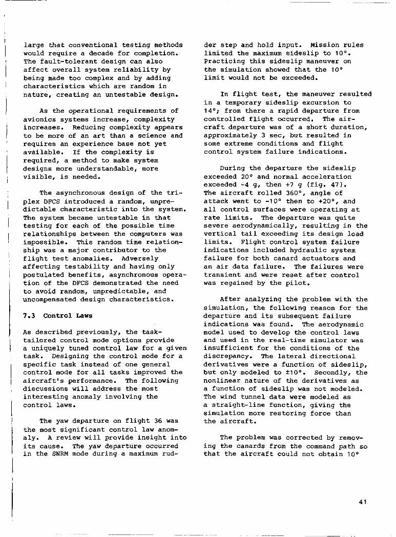
large t h a t convent iona l t e s t i n g meth d s would r e q u i r e a decade f o r completion. The f a u l t - t o l e r a n t des ign can a l s o a f f e c t o v e r a l l system r e l i a b i l i t y by be ing made t o o complex and by adding c h a r a c t e r i s t i c s which are random i n n a t u r e , c r e a t i n g an u n t e s t a b l e design.
As t h e o p e r a t i o n a l requirements of a v i o n i c s systems i n c r e a s e , complexity i n c r e a s e s . Reducing complexi ty appears t o be more of an a r t than a s c i e n c e and r e q u i r e s an exper ience base n o t y e t a v a i l a b l e . I f t h e complexity i s requ i r ed , a method to make system d e s i g n s more unders tandable , more v i s i b l e , i s needed.
The asynchronous des ign of t h e tri- p l e x DFCS in t roduced a random, unpre- d i c t a b l e c h a r a c t e r i s t i c i n t o t h e system. The system became u n t e s t a b l e i n t h a t t e s t i n g f o r each of t h e p o s s i b l e t i m e r e l a t i o n s h i p s between t h e computers w a s impossible . This random t i m e r e l a t i o n - s h i p w a s a major c o n t r i b u t o r to t h e f l i g h t t es t anomalies. Adversely a f f e c t i n g t e s t a b i l i t y and having only p o s t u l a t e d b e n e f i t s , asynchronous opera- t i o n of the DFCS demonstrated t h e need t o avoid random, unpred ic t ab le , and uncompensated des ign c h a r a c t e r i s t i c s .
7.3 Control Laws
As desc r ibed p rev ious ly , t h e task- t a i l o r e d c o n t r o l mode o p t i o n s p rov ide a uniquely tuned c o n t r o l l a w f o r a g iven task. Designing t h e c o n t r o l mode f o r a s p e c i f i c t a s k i n s t e a d of one g e n e r a l c o n t r o l mode f o r a l l tasks improved t h e a i r c r a f t ' s performance. The fo l lowing d i s c u s s i o n s w i l l add res s t h e most i n t e r e s t i n g anomaly invo lv ing t h e c o n t r o l l a w s .
The yaw depa r tu re on f l i g h t 36 w a s t h e most s i g n i f i c a n t c o n t r o l l a w anom- a l y . A review w i l l p rovide i n s i g h t i n t o i t s cause. The yaw d e p a r t u r e occurred i n t h e SNRM mode dur ing a maximum rud-
de step and hold inpu t . M i s i o n r u l e s l i m i t e d t h e maximum s i d e s l i p to 10'. P r a c t i c i n g t h i s s i d e s l i p maneuver on t h e s imula t ion showed t h a t t he 10' l i m i t would n o t be exceeded.
I n f l i g h t tes t , t h e maneuver r e s u l t e d i n a temporary s i d e s l i p excur s ion t o 14'; from t h e r e a r a p i d d e p a r t u r e from c o n t r o l l e d f l i g h t occurred. The air- c r a f t d e p a r t u r e w a s of a s h o r t d u r a t i o n , approximately 3 sec, b u t r e s u l t e d i n some extreme c o n d i t i o n s and f l i g h t c o n t r o l system f a i l u r e i n d i c a t i o n s .
During t h e d e p a r t u r e t h e s i d e s l i p exceeded 20' and normal a c c e l e r a t i o n exceeded -4 g, then +7 g ( f i g . 47) . The a i r c r a f t r o l l e d 360°, a n g l e of a t t a c k went t o -10' then t o +20°, and a l l c o n t r o l s u r f a c e s were o p e r a t i n g a t rate l i m i t s . The d e p a r t u r e w a s q u i t e s e v e r e aerodynamical ly , r e s u l t i n g i n t h e v e r t i c a l t a i l exceeding i t s des ign load l i m i t s . F l i g h t c o n t r o l system f a i l u r e i n d i c a t i o n s inc luded h y d r a u l i c system f a i l u r e f o r bo th canard a c t u a t o r s and a n a i r d a t a f a i l u r e . The f a i l u r e s were t r a n s i e n t and were reset a f t e r c o n t r o l w a s rega ined by t h e p i l o t .
A f t e r ana lyz ing t h e problem wi th t h e s imula t ion , t h e fo l lowing reason f o r t h e d e p a r t u r e and i t s subsequent f a i l u r e i n d i c a t i o n s w a s found. The aerodynamic model used t o deve lop t h e c o n t r o l l a w s and used i n the r e a l - t i m e s i m u l a t o r w a s i n s u f f i c i e n t f o r t h e c o n d i t i o n s of t h e d iscrepancy . The la teral d i r e c t i o n a l d e r i v a t i v e s were a f u n c t i o n of s i d e s l i p , b u t on ly modeled to lt10'. Secondly, t h e n o n l i n e a r n a t u r e of t h e d e r i v a t i v e s as a f u n c t i o n of s idesl ip w a s n o t modeled. The wind t u n n e l d a t a were modeled as a s t r a i g h t - l i n e f u n c t i o n , g i v i n g t h e s i m u l a t i o n more r e s t o r i n g f o r c e than t h e a i r c r a f t .
The problem w a s c o r r e c t e d by remov- i n g t h e canards from t h e command p a t h so t h a t t h e a i r c r a f t could n o t o b t a i n 10'
41

of s i d e s l i p . The h o r i z o n t a l t a i l s t r u c - t u r e w a s examined and found t o be undam- aged, and a s t r u c t u r a l mod i f i ca t ion w a s made t o t h e v e r t i c a l t a i l t o i n c r e a s e i t s load l i m i t f o r f u t u r e f l i g h t s .
The h y d r a u l i c v o t e i n t h e canard a c t u a t o r s w a s owing t o a d rop i n hydrau- l i c p r e s s u r e as a r e s u l t of a l l c o n t r o l s u r f a c e s be ing a t t h e command rate l i m - i t s . The a i r d a t a f a i l u r e , a l though appear ing t o be s t r a i g h t f o r w a r d , proved t o be q u i t e i n t e r e s t i n g . The a i r d a t a f a i l u r e w a s a t r a n s i e n t f a i l u r e caused by t h e side-mounted probe which w a s blanked by t h e f u s e l a g e a t t h e high- s i d e s l i p angles . A d e t a i l e d review of t h e t h r e e computers' s u r f a c e commands showed a mis t r ack ing d u r i n g t h i s f a i l - ure . Analysis showed t h e S / M t echnique passed t h e s i d e probes e r r o r through u n t i l t h e f a i l u r e t h r e s h o l d w a s reached ( f i g . 4 8 ) . The a i r data in fo rma t ion i s used t o determine f l i g h t c o n t r o l l a w g a i n s asynchronously a t 4 t i m e s per sec. The a i r d a t a f a i l u r e t r a n s i e n t , shown i n f i g u r e 49, caused changes t o t h e c o n t r o l l a w g a i n s , g i v i n g d i f f e r e n t c o n t r o l s u r - f ace commands i n t h e t h r e e channels.
F o r t u n a t e l y , a t t h e f l i g h t c o n d i t i o n of t h e d e p a r t u r e , t h e g a i n changes d i d n o t produce d i f f e r e n c e s which would cause f a i l u r e d e c l a r a t i o n s of t h e com- puters. For several areas of t h e f l i g h t envelope, p a r t i c u l a r l y a t h igh ang le s of a t t a c k , t h i s s i n g l e a i r d a t a f a i l u r e would r e s u l t i n f a i l u r e of t h e DFCS t o t h e ana log backup. This i n c r e a s e d r i s k w a s accepted u n t i l t h e so f tware w a s modified.
S e v e r a l p o i n t s should be noted from t h i s f l i g h t i n c i d e n t :
1 . Any s i m p l i f i c a t i o n i n t h e model- i n g of t h e aerodynamics must ensu re t h a t i t i s conse rva t ive wi th respect t o i t s e f f e c t s on t h e a i r c r a f t as a whole.
2. The a i r c r a f t must be cons idered a system c o n s i s t i n g of h igh ly r e l a t e d d i s c i p l i n e s and func t ions . The c o n t r o l l a w des ign e r r o r caused by t h e modeling e r r o r r evea led des ign e r r o r s i n t h e hy- d r a u l i c system and DFCS f a u l t d e t e c t i o n l o g i c . The a i r c r a f t s t r u c t u r e became involved due t o c o n t r o l l a w des ign e r r o r .
3 . To thoroughly q u a l i f y an a i r c r a f t w i th t h e s e types of systems, one must
A. model d i s s i m i l a r s e n s o r s com- p l e t e l y , i n c l u d i n g s i d e s l i p e f f e c t s ;
B. tes t wi th t h e a i r c r a f t i n t h e loop wi th t h e s imula t ion , t he reby in - c l u d i n g t h e a c t u a t i o n system;
C. tes t f a i l u r e modes o t h e r t han hardover f a i l u r e s ; and
D. have a complete under- s t a n d i n g of t h e DFCS des ign and i t s i n t e r r e l a t i o n s h i p s .
7.4 Hardware
The DFCS hardware i n c l u d e s t h e F-16 b a s e l i n e s e n s o r s and c o n t r o l l e r s and t h e AFT1 f l i g h t c o n t r o l computers and a c t u a t o r i n t e r f a c e u n i t . Based on r e p e a t a b l e , i s o l a t e d f a i l u r e s , t h e r e l i a b i l i t y of t h e hardware w a s exce l - l e n t . In t h e 175 h r of i n - f l i g h t t e s t , a n e lec t r ica l connec tor w a s t h e on ly hardware f a i l u r e . In t h e 6200 h r of ground t i m e , i n c l u d i n g t i m e p r i o r t o f l i g h t t e s t , on ly t h r e e f a i l u r e s were documented i n t h e computers. To d e t e r - mine computer r e l i a b i l i t y , t h e t i m e mus t be m u l t i p l i e d by t h r e e , f o r t h e t h r e e computers used i n t h e system. This g i v e s a 6200-hr mean-time-between f a i l - u r e s compared t o a p r e d i c t e d 1200 h r .
The most s i g n i f i c a n t problem t o a d d r e s s l i e s i n t h e number of nonre-
42
I

p e a t a b l e f a i l u r e s and f a i l u r e ind ica - t i o n s l i s t e d i n t a b l e 22 and d i scussed i n s e c t i o n 7.2. Depending on one ' s o p e r a t i n g r u l e s , these f a i l u r e s can r e s u l t i n cons ide rab le equipment changes and loss of a i r c r a f t a v a i l a b i l i t y .
7.5 Software
The use of a DFCS enab le s changes t o t h e sys tems ' c h a r a c t e r i s t i c s , such as f l y i n g q u a l i t i e s , by reprogramming t h e s o f t - ware. E f f i c i e n t and s a f e f l i g h t t e s t r e q u i r e s a thorough method f o r eva l - u a t i n g , implementing, and t e s t i n g s o f t w a r e .changes.
I n t h e 1 y r of f l i g h t t e s t i n g , 129 so f tware changes w e r e made i n 13 sepa- rate releases ( f ig . 50). A so f tware release is a package of changes pro- v ided i n one update.
The p rocess of changing t h e so f tware i s d e s c r i b e d i n s e c t i o n 6. The m a j o r i t y o f t h e e v a l u a t i o n , implementation, and t e s t i n g occurred a t t h e c o n t r a c t o r ' s f a c i l i t y . The J o i n t T e s t Force, cons is - t i n g of t h e A i r Force F l i g h t T e s t Center and NASA, p layed two major r o l e s i n t h e s o f t w a r e process . F i r s t , it i d e n t i f i e d changes t h a t were needed and t h e i r t i m - i n g f o r release, and second it provided a n independent a u d i t of t h e changes. The a u d i t inc luded independent va l ida- t i o n t e s t i n g a t the c o n t r a c t o r ' s facil- i t y and review of suppor t ing so f tware p roduc t s , s u c h as the documentation.
Three e r r o r s w e r e found i n the s o f t w a r e releases a f t e r t hey had been approved f o r f l i g h t test. All r e s u l t e d from changes, and none w e r e l a t e n t er- r o r s which e x i s t e d f o r s e v e r a l releases. Two of t h e e r r o r s w e r e found i n ground p r e f l i g h t tests, and one w a s d e t e c t e d d u r i n g f l i g h t .
A so f tware e r r o r i s de f ined as t h e software n o t o p e r a t i n g i n accordance w i t h i t s s p e c i f i c a t i o n .
The f i r s t e r r o r i n t h e so f tware re- s u l t e d from a change to t h e B I T s o f t - ware. The change w a s t o cause B I T t o f a i l i f it d e t e c t e d a p a r i t y error i n t h e hardware. One f u n c t i o n of B I T w a s t o read a memory l o c a t i o n wi th known bad p a r i t y and t o check f o r p a r i t y e r r o r d e t e c t i o n by the hardware. The so f tware used t o d e t e c t u n i n t e n t i o n a l p a r i t y e r r o r s also d e t e c t e d t h e pu rpose fu l one, caus ing the B I T t o f a i l e r roneous ly .
The second so f tware error involved t h e s t r u c t u r a l l i m i t f o r t h e v e r t i c a l t a i l . The s t r u c t u r a l load w a s l i m i t e d by r e s t r i c t i n g t h e rudder command as a f u n c t i o n of impact p r e s s u r e and f l i g h t c o n t r o l mode ( f i g . 51) . During f l i g h t tes t , it w a s found t h a t t h e v e r t i c a l t a i l l o a d s were exceeding t h o s e d e s i r e d w i t h t h e rudder l i m i t implemented. Sev- e ra l o p t i o n s t o c o r r e c t t h e problem w e r e engineered and eva lua ted wi th t h e hardware-in-the-loop s imula t ion . The b e s t o p t i o n w a s i d e n t i f i e d and inc luded i n t h e n e x t f l i g h t release. Unfortu- n a t e l y , one of t h e o t h e r o p t i o n s be ing eva lua ted w a s a c c i d e n t a l l y l e f t i n t h e sof tware . The error w a s found d u r i n g ground t e s t i n g which checked t h e i n s t a l - l a t i o n of t h e new so f tware i n t o t h e air- c r a f t . T e s t s showed t h a t t h e rudde r w a s be ing l i m i t e d to smaller d e f l e c t i o n s than those expected. The so f tware error gave a c o n s e r v a t i v e l i m i t f o r v e r t i c a l t a i l l oads , b u t r e s u l t e d i n unnecessary o p e r a t i o n a l l i m i t s . A d e c i s i o n w a s made to use the so f tware release u n t i l i t cou ld be c o r r e c t e d i n t h e n e x t update.
The l a s t so f tware e r r o r w a s d i s - cussed i n s e c t i o n 7.2. I t involved a change to t h e so f tware , v o t i n g a s o f t - ware swi t ch , caus ing a l l t h r e e computers s imul t aneous ly t o use the same c o n t r o l l a w pa ths . Although e x t e n s i v e l y t e s t e d p r i o r to f l i g h t with software u n i t tests and hardware-in-the-loop tests, t h e anomaly w a s n o t d e t e c t e d u n t i l f l i g h t t es t . The so f tware error w a s one of c o r r e c t l y v o t i n g t h e t h r e e computers'
43

de te rmina t ion t o togg le a so f tware swi t ch , b u t then n o t u s i n g t h a t voted va lue f o r t h e a c t u a l swi t ch ing a c t i o n . The p rev ious method w a s s t i l l i n e f f e c t , t h a t i s , each computer channel d e t e r - mined i t s own swi tch ing . F l i g h t tests under t h e c o n d i t i o n s t h a t would a l low t h i s e r r o r to occur , which w e r e a func- t i o n of c o n t r o l mode, w e r e p r o h i b i t e d u n t i l t h e nex t so f tware release.
8 OBSERVATIONS AND RECOMMENDATIONS
Each of the f o u r l i f e - c y c l e phases are p u l l e d t o g e t h e r i n t h i s s e c t i o n to examine how they a f f e c t one ano the r . The approach i n t h i s s e c t i o n i s t o f i r s t g i v e a d e t a i l e d case s tudy , then t o summarize each of t h e development phases. Emphasis w i l l be on how t h e f l i g h t tes t phase was affected by the p rev ious t h r e e phases - s p e c i f i c a t i o n , des ign , and test. Comments are a l s o g iven which on ly r e f e r t o a s i n g l e l i f e - c y c l e phase, such as recommendations t h a t would provide f o r a more e f f i c i e n t q u a l i f i c a t i o n . A f t e r completing the case s tudy , a review of t h e p rev ious t h r e e development phases g i v e s t h r e e p e r s p e c t i v e s on h o w anomalies can be avoided and how t o maximize t h e bene- f i t s of f l i g h t t e s t i n g . Looking a t system-sof tware q u a l i f i c a t i o n , w e see t h a t more complete and e f f i c i e n t test- i n g i s needed. Looking a t des ign , w e see that o p e r a t i o n a l b e n e f i t s can be achieved by improving system a r c h i t e c - t u r e . F i n a l l y , when c o n s i d e r i n g the system s p e c i f i c a t i o n , we see t h a t i f s u f f i c i e n t d e t a i l e x i s t s t o i d e n t i f y e x a c t l y what is d e s i r e d , then a cor- rect d e s i g n i s more l i k e l y . The case s t u d y from f l i g h t tes t w i l l h e l p t o c l a r i f y each of these concepts. Fol- lowing t h e case s tudy , recommendations f o r each l i f e c y c l e are summarized.
8.1 Anomaly of F l i g h t 44, A C a s e Study
The anomaly of f l i g h t 44, d i s c u s s e d i n s e c t i o n 7, p rov ides a good example t o i l l u s t r a t e how a c t i v i t i e s of t h e pre- v ious l i f e - c y c l e phases c o n t r i b u t e d to a f l i g h t - t e s t anomaly. The anomaly w a s owing t o a des ign o v e r s i g h t and r e q u i r e d s e v e r a l unique c o n d i t i o n s , which are o u t l i n e d as fo l lows ( f i g . 5 2 ) :
1 . Standard combat o r a decoupled f l i g h t c o n t r o l mode had t o be a c t i v e .
2. The p i l o t had to have f u l l rud- d e r peda l s , f l y i n g a t 170 k n o t s cali- b r a t e d airspeed (KCAS).
3 . Sensor n o i s e coupled wi th com- p u t e r skew had t o g ive a 3-knot d i f - f e r e n c e i n t h e impact pressure va lues i n t h e t h r e e computer channels.
I n the f l i g h t c o n t r o l modes i d e n t i - f i e d , a rudder f a d e r , s chedu le D 6 9 , removes p i l o t commands below 170 KCAS, f o r c o n t r o l l a b i l i t y reasons. The d i f - f e r e n c e i n the pe rce ived airspeed f o r the t h r e e d i f f e r e n t channe l s allowed d i f f e r e n t amounts of t h e fu l l - rudde r - pedal commands t o pass through schedu le D 6 9 . The t h r e e d i f f e r e n t pedal commands i n i t i a l i z e d each c h a n n e l ' s i n t e g r a t o r , r e s u l t i n g i n a d ive rgence of t h e o u t p u t commands t o t h e canard s u r f a c e s . Each of t h e t h r e e computer channe l s d e c l a r e d t h e o t h e r two as f a i l e d . The a i r c r a f t w a s landed e f f e c t i v e l y wi th a s i n g l e s t r i n g f l i g h t c o n t r o l system.
8 . 1 . 1 S p e c i f i c a t i o n
C l e a r l y , it is n o t d e s i r a b l e t o have a system d e s i g n t h a t can cause loss of system redundancy when no f a i l u r e e x i s t s . However, t h e r e i s no th ing i n t h e s p e c i f i c a t i o n s which addresses i n c o r r e c t f a i l u r e d e t e c t i o n .
44

R e l i a b i l i t y requirements simply addres s component f a i l u r e s . Once you s p e c i f y t h a t i n c o r r e c t f a i l u r e d e t e c t i o n is n o t acceptable, cr i ter ia are needed t o en- s u r e it. This has been a matter of eng inee r ing judgment t o da t e .
Recommenda ti on
I n c o r r e c t f a u l t d e t e c t i o n , r e s u l t i n g i n i n a p p r o p r i a t e l o s s of system redun- dancy, is unacceptable . The cri teria f o r ensu r ing proper o p e r a t i o n should b e t o tes t voted-compared va lues wi th i n p u t s t h a t r e p r e s e n t t h e p h y s i c a l l i m i t s of t h e device-system i n ques t ion . The p h y s i c a l l i m i t s t o cons ide r i nc lude rate of change, minimum and maximum va lues , maximum frequency response, and no i se , as examples.
8.1.2 Design
The des ign change needed t o avoid t h i s anomaly is one ensu r ing t h a t t h e same va lue of a senso r is used i n a l l redundant channels . Simultaneous sen- sor sampling and proper senso r selec- t i o n r o u t i n e s would ensu re congruent sensor va lues .
Recommenda t i o n
Redundant system des igns which use v o t i n g and cross-channel comparisons t o d e t e c t f a u l t s must o p e r a t e on congruent i n p u t data sets to avoid incorrect f a i l u r e d e t e c t i o n .
8 . 1 . 3 Q u a l i f i c a t i o n
For t h e system-software q u a l i f i - c a t i o n a c t i v i t y , s e v e r a l gene ra l i zed techniques should be used t o d e t e c t t h e anomaly of f l i g h t 44 prior to f l i g h t test . Tes t ing t h e c o n t r o l mode con- d i t i o n for t h e anomaly is e a s i l y done, i n fact t h e s e c o n t r o l modes were t e s t e d for months us ing t h e ho t bench simula- t i o n . The rudder f a d e r , l i kewise , w a s tested numerous t i m e s .
However, t h e amount of impact pres- s u r e error i n the d i f f e r e n t channels w a s never enough to cause t h e problem t o appear dur ing ground t e s t i n g . Sensor n o i s e and computer skew w e r e two param- eters which w e r e n o t c o n t r o l l e d , nor were t h e e x a c t t r i p l e x va lues known dur ing t h e ground t e s t i n g .
Recommendations
1 . F a u l t - t o l e r a n t system des ign must be eva lua ted f o r s e n s i t i v i t y t o senso r noise .
2. A computerized d e s c r i p t i o n of t h e f l i g h t c o n t r o l system i s needed to .
i d e n t i f y c o n d i t i o n s , c o n t r o l modes, and f l i g h t c o n d i t i o n s f o r doing s e n s o r n o i s e s e n s i t i v i t y tests. The computerized system d e s c r i p t i o n would accept u s e r i n p u t s , such as f l i g h t c o n d i t i o n s and c o n t r o l modes, and r e t u r n a c t i v e com- mand p a t h s a p p r o p r i a t e f o r s enso r sen- s i t i v i t y tests.
3. Random unmeasured system param- eters such as computer skew must be l i m i t e d . I f t hey c a n ' t be l i m i t e d , a d d i t i o n a l t e s t i n g is needed to g e t a s ta t i s t ica l base f o r p r e d i c t i n g i t s e f f e c t on system ope ra t ions .
8.2 Observa t ions and Recommendations by Development Phase
To minimize t h e d e t a i l e d d i s c u s s i o n s needed t o review eve ry f l i g h t anomaly and t h e a n a l y s i s used to a r r i v e a t each recommendation, we w i l l b r i e f l y describe t h e obse rva t ions and recommendations as they apply t o each development phase.
8.2.1. S p e c i f i c a t i o n
The pr imary obse rva t ion concern- i n g t h e s p e c i f i c a t i o n s i s t h e l a c k of d e t a i l e d s p e c i f i c a t i o n s f o r r e l i a b i l i t y and f a u l t t o l e rance . "he m a j o r i t y of t h e s p e c i f i c a t i o n s is concerned wi th s t a b i l i t y and c o n t r o l requi rements f o r
45

convent iona l , nondecoupled c o n t r o l system des igns .
Recommendations
1 . In a d d i t i o n t o t h e l o s s of con- t r o l and a b o r t s p e c i f i c a t i o n s , f a i l u r e p r o b a b i l i t i e s should be g iven f o r t h e d i f f e r e n t mission phases and t h e func- t i o n s performed by t h e f l i g h t c o n t r o l system. By s p e c i f y i n g a b o r t p robab i l - i t i e s f o r d i f f e r e n t miss ions , such as a i r - t o - a i r i n t e r c e p t and a i r - t o - s u r f a c e bombing, t h e d e s i g n e r can avoid e i t h e r over- o r underdesigning t h e system. The r e l i a b i l i t y of f u n c t i o n s , such as p i l o t d i s p l a y s and c o n t r o l s , should l i k e w i s e be g iven r e l i a b i l i t y va lues .
2. R e l i a b i l i t y requi rements need t o a d d r e s s t h e so f tware by i d e n t i f y i n g t h e t e s t i n g methods and t o o l s t o be used and by c l e a r l y s t a t i n g t h e requi rements of any independent backup, whether hardware o r so f tware i n na tu re . The key t o s o f t - w a r e r e l i a b i l i t y is n o t found i n a f a i l - u r e rate, b u t i n t h e examination of t h e method and t o o l s used t o ensu re p rope r f u n c t i o n a l i t y . The s o f t w a r e ' s l i f e c y c l e of s p e c i f i c a t i o n , des ign , and tes t must be s p e c i f i e d so t h a t t e s t i n g i s traceable t o t h e requi rements , and p rope r f u n c t i o n a l i t y i s shown. The ap- pendix p rov ides some de ta i led t e s t i n g examples f o r c o n t r o l l a w f u n c t i o n s .
Requirements f o r an independent backup should i n c l u d e ( 1 ) method f o r d e t e c t i n g t h e need f o r a t r a n s i t i o n t o t h e backup, whether manual or au tomat ic , ( 2 ) a l lowab le t r a n s i t i o n p e r i o d s and t r a n s i e n t s , and ( 3 ) f u n c t i o n a l r equ i r e - ments of backup, such as o p e r a t i n g enve- l o p e and r e l i a b i l i t y . I f t h e backup is going t o be f l i g h t tested, reengagement of t h e primary system must be addressed.
3 . F a i l u r e t r a n s i e n t s should be s p e c i f i e d i n terms of t h e r e s u l t i n g aerodynamic and s t r u c t u r a l e f f e c t s . Table 27 i s an example of maximum aero-
dynamic f a i l u r e t r a n s i e n t requi rements , which vary wi th mission. A t c e r t a i n c o n d i t i o n s , such as high-impact pres- s u r e s , a s u r f a c e t r a n s i e n t can r e s u l t i n s t r u c t u r a l damage wi th l i t t l e aero- dynamic t r a n s i e n t . Table 28 shows a p o s s i b l e s p e c i f i c a t i o n f o r s t r u c t u r a l t r a n s i e n t s by g i v i n g f l i g h t c o n d i t i o n and s u r f a c e t r a n s i e n t a l lowab le , t he reby implying f l i g h t loads . The c o n d i t i o n s would be de r ived from c a l c u l a t i o n s which de termine excess s t r u c t u r a l l oads .
8.2 .2 . Design
Some obse rva t ions and g e n e r i c recom- mendations f o r des ign ing f a u l t - t o l e r a n t c o n t r o l systems are p resen ted i n t h i s s e c t i o n . The major theme of t h e recom- mendations i s based on t h e l i f e c r i t i - c a l i t y of the c o n t r o l system and han- d l i n g t h e complexity imposed by redundant s y s t e m s .
Reviewing t h e methods used t o deve lop t h e system a r c h i t e c t u r e , s o f t - ware, and c o n t r o l l a w d e s i g n s shows t h a t bo th the method used t o s p e c i f y t h e con- t r o l l a w s and t h e t o o l s a v a i l a b l e t o deve lop them are more mature than f o r t h e o t h e r two. Whereas, some so f tware t o o l s are a v a i l a b l e f o r the so f tware development p rocess , t o o l s to assist i n s p e c i f y i n g and performing t r a d e o f f s t u d i e s are needed. Tools do n o t e x i s t f o r t h e system a r c h i t e c t u r e and f a u l t - t o l e r a n t d e s i g n t a s k .
There i s no i n t e g r a t i o n of t o o l s f o r t h e t h r e e d i s c i p l i n e s . For example, D I G I K O N , used t o deve lop the c o n t r o l l a w s , ha s a d a t a base which d e s c r i b e s t h e c o n t r o l l a w s . D I G I K O N i s n o t t i e d t o any of t h e so f tware development tools. A l a b o r i o u s handmade descrip- t i o n of t h e c o n t r o l l a w des ign had t o be w r i t t e n f o r the so f tware mechaniza- t i o n document.
I f a system made of t h e s e t h r e e e lements is t o work as a whole, deve l -
I
I I
I
I
46
opment and i n t e g r a t i o n of des ign and development t o o l s are needed.
Recommendations
1 . An i n t e g r a t e d des ign t o o l , which a d d r e s s e s c o n t r o l l a w s , f a u l t t o l e r a n c e , hardware, and so f tware , is needed f o r f a u l t - t o l e r a n t c o n t r o l systems. A few of t h e c a p a b i l i t i e s needed i n such a t o o l i n c l u d e t h e fo l lowing:
A. Documentation of the system d e s i g n i n a computer d a t a base which relates the d i f f e r e n t f u n c t i o n a l areas. The d a t a base would be quer- i e d t o f i n d p o s s i b l e i n t e r a c t i o n s , such as s e n s o r n o i s e , a f f e c t i n g com- mand p a t h s i n t h e c o n t r o l l a w s .
B. Eva lua t ion of t h e system d e s i g n f o r f a u l t t o l e r a n c e , c o n t r o l l a w s , and so f tware execu t ion p r i o r t o a c t u a l system bu i ld . The a b i l i t y t o ana lyze t h e des ign and make cor- r e c t i o n s p r i o r to b u i l d i n g hardware and so f tware code would reduce rede- s i g n d u r i n g q u a l i f i c a t i o n .
2. When des ign ing i n t e r f a c e s t o a redundant f l i g h t c o n t r o l system, one must c a r e f u l l y c o n s i d e r t h e c r i t i c a l i t y of the in fo rma t ion be ing passed and t h e f a i l u r e modes t h a t are p o s s i b l e . This r e q u i r e s a detai led unders tanding of t h e items be ing i n t e r f a c e d . A case i n p o i n t w a s the I S A and f l ight control system i n t e r f a c e . Add i t iona l t e s t i n g of t h e I S A w a s needed to des ign i t s i n t e r f a c e .
3 . The a v i o n i c s i n t e r f a c e is an example where no redundancy e x i s t e d f o r many of t h e f a i l u r e modes possible. The in fo rma t ion passed from the a v i o n i c s w a s c r i t i ca l enough t o have caused a f a i l u r e o f t h e DFCS. The redundancy r equ i r ed i n a n i n t e r f a c e must be based on t h e c r i t i - c a l i t y of t h e in fo rma t ion and t h e pos- s i b l e f a i l u r e modes.
4. A f a u l t - t o l e r a n t system, which u s e s c ross -channel v o t i n g t o d e t e c t f a i l u r e s , should avoid random, unmeas- u r a b l e des ign c h a r a c t e r i s t i c s , such as asynchronous channel ope ra t ion . Th i s h e l p s t o keep f a i l u r e t h r e s h o l d s a t low l e v e l s and minimizes unexpected i n t e r a c - t i o n s t h a t can r e s u l t from incongruen t d a t a sets.
The f a u l t - t o l e r a n t des ign should a l s o be t r a n s p a r e n t t o t h e c o n t r o l l a w f u n c t i o n s . The c o n t r o l l a w s should n o t have t o be t a i l o r e d t o t h e sys tem's redundancy l e v e 1.
8.2.3 Qualification
The l e a d i n g i s s u e i n q u a l i f y i n g o r t e s t i n g complex DFCSs are completeness and c o s t . T e s t completeness is an i s s u e wi th any sof tware-dr iven system, b u t becomes a major i t e m when t h e system has f u l l a u t h o r i t y c o n t r o l of a p i l o t e d air- craft . Determining some l e v e l of tes t completeness is a l s o d i f f i c u l t because o f t h e complexity - number of dependent i n p u t s and number of o p e r a t i n g modes. The appendix p rov ides some sugges t ions f o r complete t e s t i n g of c o n t r o l l a w s .
Cos t , t h e o t h e r l e a d i n g i s s u e , re- s u l t s d i r e c t l y from the e f f o r t needed t o completely t e s t complex s y s t e m s t o a reasonable l e v e l . Rather than achiev- i n g a measurable l e v e l of tes t complete- ness or by meeting established criteria, t h e amount of t e s t i n g performed o f t e n becomes l i m i t e d by c o s t .
Recommendations
1 . System-software q u a l i f i c a t i o n t e s t i n g must be performed t o e n s u r e i m - p l emen ta t ion of the requi rements , and t h a t each requi rement is tested t o meet a n e s t a b l i s h e d c r i t e r i o n . For example, a system requirement f o r decoupled con- t r o l would r e s u l t i n a cor responding
47
so f tware requirement, i d e n t i f y i n g spe- c i f i c c o n t r o l l a w components, such as those g iven i n t h e appendix.
T e s t i n g must be i d e n t i f i e d f o r both t h e system and t h e de t a i l ed so f tware requirements. The t e s t i n g must be com- plete enough t o v e r i f y t h e requi rements are m e t a t both l e v e l s . A t o o l o r method i s needed t o ensu re tes t cov- e r a g e of a l l so f tware components.
2. Tools t h a t s u p p o r t automation of t h e v e r i f i c a t i o n task should be used. Automated tes t s t i m u l u s , data reco rd ing , and a n a l y s i s can p rov ide f o r more thor - ough tests, b e t t e r tes t documentation, and more e f f i c i e n t use of personnel . The use of q u a l i t a t i v e pass-fail cri- teria, such as r easonab le t r a n s i e n t s and a c c e p t a b l e d i f f e r e n c e s , should be avoided.
T e s t automation w i l l r e q u i r e real- time i n s t r u m e n t a t i o n of i n t e r n a l s o f t - ware c a l c u l a t i o n s . The system d e s i g n w i l l need t o s u p p o r t t h e special test requi rements f o r p rov id ing v i s i b i l i t y i n t o t h e system.
3 . A computerized on - l ine d e s c r i p - t i o n of t h e system (see recommendation 1 , s e c t i o n 8 . 2 . 2 ) should be a v a i l a b l e t o tes t eng inee r s . This d a t a base of d e s i g n in fo rma t ion w i l l a s s i s t t h e tester i n de te rmining t es t c o n d i t i o n s , f u n c t i o n a l i n t e r a c t i o n s , and param- eters t o r eco rd f o r a s s e s s i n g proper tes t r e s u l t s . The d a t a base would a l s o be va luab le f o r de te rmining t h e cause of d i s c r e p a n c i e s .
4. System t e s t i n g must c o n s i d e r t h e o p e r a t i n g environment i n which i t i s going t o be used. v i b r a t i o n and t e m - p e r a t u r e e f f e c t s on senso r va lues used by t h e c o n t r o l system must be modeled. These e f f e c t s can e a s i l y be implemented by imposing b i a s e s and n o i s e on t h e s i m - u l a t e d senso r values.
8.2.4 Fl ight Test
By f a r , t h e b e s t t h i n g t h a t can h a p pen t o a f l i g h t test program is t o have thorough s p e c i f i c a t i o n s , a good d e s i g n , and a complete and e f f i c i e n t q u a l i f i c a - t i o n . The f a c t t h a t more anomalies and f l i g h t test t i m e were l o s t owing to d e s i g n o v e r s i g h t s than a c t u a l compo- n e n t f a i l u r e s at tests to t h e need f o r improving the development cyc le s .
Some s p e c i f i c recommendations from f l i g h t tes t fo l low.
Recommenda t i o n s
1 . To ensu re t h e b e s t system con- f i g u r a t i o n f o r r e t e s t i n g of changes and c o r r e c t i o n s d u r i n g f l i g h t tes t and t o minimize downtime t o r e s o l v e f l i g h t anomal ies , it i s recommended t h a t t h e a i rc raf t des ign i n c l u d e t h e c a p a b i l i t y of c l o s i n g the aerodynamic loop around t h e a i r c r a f t wi th t h e f l i g h t a v i o n i c s i n s t a l l e d . T h i s c o n f i g u r a t i o n minimizes t h e number of unknowns involved when t e s t i n g . Unexpected i n t e r a c t i o n s which have n o t been modeled can be d e t e c t e d .
2. A computerized d a t a base de- s c r i b i n g t h e a i r c r a f t ' s f l i g h t system would g r e a t l y h e l p f l i g h t test. Used as a n e d u c a t i o n a l t o o l € o r new e n g i n e e r s , i t could reduce t h e l e a r n i n g curve. As d u r i n g the system q u a l i f i c a t i o n , i t would be v a l u a b l e f o r t r o u b l e s h o o t i n g f l i g h t test d i s c r e p a n c i e s .
3 . Inc reased v i s i b i l i t y i n t o t h e d i g i t a l system r e q u i r e s i n s t r u m e n t a t i o n of i n t e r m e d i a t e so f tware c a l c u l a t i o n s . To e f f e c t i v e l y ana lyze system perform- ance and r e s o l v e anomalies, data from i n t e r n a l c a l c u l a t i o n s are r e q u i r e d a t t h e frame ra te they are be ing c a l c u l a t e d . The a i r c r a f t f l i g h t i n s t r u m e n t a t i o n sys- t e m and p o s t f l i g h t a n a l y s i s systems w i l l need t o s u p p o r t t h e i n c r e a s e d d a t a f low 1 imposed by t h i s requirement. I
48

9 CONCLUDING REMARKS
The f l i g h t test program on the AFTI F-16 v a l i d a t e d t h e concepts of decoupled f l i g h t control and t h e i n t e g r a t i o n of a v i o n i c s func t ions i n t h e c o c k p i t to reduce p i l o t workload. J u s t as impor- t a n t , it provided a chance to e v a l u a t e t h e t o o l s and methods used i n i t s devel- opment. The performance c a p a b i l i t i e s demonstrated by t h e AFTI F-16 r equ i r ed a new, h igher l e v e l of a v i o n i c s com- p l e x i t y . F l i g h t t e s t i n g provided t h e environment and c o n d i t i o n s to uncover t h e des ign advantages and ove r s igh t s .
To minimize the o v e r s i g h t s t h a t came from working a t t h e l ead ing edge of technology, recommendations are g iven t o improve a l l t h e development phases. For t h e s p e c i f i c a t i o n phase, a l lowable f a i l u r e t r a n s i e n t s are p resen ted which s p e c i f y t h e a i r c r a f t motion and s t r u c - t u r a l loads pe rmi t t ed owing t o a f l i g h t c o n t r o l system f a i l u r e .
The asynchronous d i g i t a l c o n t r o l system des ign i s reviewed and t h e prob- l e m s of us ing t h i s approach examined. Crea t ing a computerized d e s c r i p t i o n of t h e system des ign i s proposed t o h e l p e v a l u a t e des igns p r i o r to committing t o b u i Id.
For t h e t e s t i n g phase, s e v e r a l recommendations are g iven t o h e l p reduce cost and f l i g h t t es t r i s k . Automated sof tware t e s t i n g is one approach proposed.
The b e n e f i t s shown dur ing f l i g h t test of t h e decoupled c o n t r o l modes are p resen ted , showing t h e advantages of commanding d i r e c t s i d e f o r c e . The anoma- l i es d iscovered i n f l i g h t t e s t i n g are expla ined i n d e t a i l , w i th r e f l e c t i o n s on how they might have been avoided.
Overa l l , t h e i n t e g r a t e d d i g i t a l con- t r o l system provided many o p e r a t i o n a l b e n e f i t s . The hardware r e l i a b i l i t y of t h e complex system w a s e x c e l l e n t . How- e v e r , t h e complexity of t h e system, cou- p l ed with the wide range of d i s c i p l i n a r y eng inee r s involved, caused numerous des ign ove r s igh t s .
National Aeronautics and Space Administration Ames Research Center Dryden Flight Research Facility Edwards, California, January 13, 1986
49

APPENDIX - VERIFICATION REQUIREMENTS CONTROL LAW
One r e q u i r e d l e v e l which f l i g h t - c r i t i c a l control l a w s must be t e s t e d t o i s spec- i f i e d i n t h i s appendix. This t e s t i n g i s performed i n t h e a c t u a l hardware environment wi th a l l sof tware operat- i n g t o show #a t t h e c o n t r o l l a w s oper- a t e p r o p e r l y wi th , and i n t h e presence o f , a l l o t h e r sof tware r o u t i n e s . T h i s method f o r t e s t i n g complex c o n t r o l l a w s o f t w a r e i s based on a d i v i d e and con- quer philosophy.
The c o n t r o l l a w s are broken down i n t o i n d i v i d u a l b locks for which t h e r e i s one i n p u t and one output . These i n d i v i d u a l blocks are t e s t e d , and i n t e r - connec t ions between t h e b locks are checked. S t a t i c checks should be done f i r s t , fol lowed by t h e r e q u i r e d dynamic tests. A f t e r t h e l o w e r l e v e l s are t e s t e d , end-to-end checks f o r compar- i s o n t o e q u i v a l e n t FORTRAN-implemented control l a w s are done. The fo l lowing w i l l address t h e method i n which lower l e v e l s can be t e s t e d i n t h e a c t u a l hardware environment wi th a l l s o f t - ware p r e s e n t .
Step 1
Break down t h e c o n t r o l l a w s i n t o i n d i v i d u a l blocks. F igures 53 and 54 are l a t e r a l - d i r e c t i o n a l c o n t r o l l a w diagrams. One s e c t i o n of t h i s diagram h a s been broken down i n t o modules and i s shown i n f i g u r e 55. This breakdown needs t o be r e f i n e d t o provide f u n c t i o n s w i t h one i n p u t and one output . Fig- u r e 56 shows t h e breakdown to i n d i v i d - u a l blocks. Blocks can be combined f o r t e s t i n g provided proper implementation can s t i l l be shown.
qui red . A list of dynamic and special tests which need to be performed fo r each f u n c t i o n follows.
Variable Gains Scheduled on Air Data and Other Parameters
Sweep through t h e f u l l range of t h e s c h e d u l i n g parameters whi le r e c o r d i n g t h e g a i n va lues . An i n p u t a g a i n s t out- p u t cross-plot r o u t i n e w i l l p r o v i d e d a t a f o r comparison t o t h e s p e c i f i c a t i o n .
Fixed Gain
Modify t h e g a i n and r e r u n t h e sta- t i c check. This checks t h e g a i n ' s posi- t i o n i n t h e c o n t r o l l a w loop and proper s c a l i n g e f f e c t .
Dynamic Elements, Filters, Integra tors
Step i n p u t s are a p p l i e d t o t h e i n p u t wi th r e s u l t i n g o u t p u t t i m e h i s - t o r y responses recorded. Comparisons t o independent ly implemented elements are made to show i d e n t i c a l t i m e h i s - t o r y responses .
Nonlinear Elements, St ick Shaping, L i m i t e r s , Deadband
These elements r e q u i r e f u l l - r a n g e i n p u t sweeps wi th o u t p u t s recorded. Cross-plots of i n p u t a g a i n s t o u t p u t can be compared to d e s i g n d a t a .
Multipl iers
M u l t i p l i e r s are checked i n t h e sta- t i c checks; f u l l - r a n g e pos i t ive and neg- a t i v e va lues should be checked. Proper system response t o overflow c o n d i t i o n s must be tested.
Summing Junctions Step 2
I d e n t i f y t y p e s of f u n c t i o n a l b locks t o be t e s t e d and t h e type of tests re-
Summing j u n c t i o n s are a lso checked i n s ta t ic tests; f u l l - r a n g e p o s i t i v e and n e g a t i v e i n p u t s are requi red .
50

Switching Functions
The swi t ch connec t ion and t h e func- t i o n s which cause the swi t ch ing a c t i o n are t e s t e d . Do n o t attempt t o togg le t h e swi t ch by f o o l i n g a memory l o c a t i o n ; se t up a c t u a l i n p u t c o n d i t i o n s which cause t h e swi tch ing a c t i o n .
Block Interconnects
I n t h e s ta t ic checks, t h e o u t p u t of each block is checked f o r proper connec- t i o n t o o t h e r block i n p u t s .
Scheduled D y n a m i c Elements, Filters Scheduled on Air D a t a
This type of so f tware f u n c t i o n i s imposs ib l e t o tes t completely. The scheduled va lue must be t e s t e d l i k e t h e v a r i a b l e ga ins . S e v e r a l va lues must be chosen f o r t h e v a r i a b l e wi th s tep responses measured. worst case and extreme va lues should be used.
R a t e Checks, R a t e L i m i t e r s
R a t e checks must be t e s t e d j u s t below and j u s t above t h e rate check l e v e l . The s i g n a l should be passed u n a l t e r e d below the l e v e l . Above t h e rate check or l i m i t , f l a g g i n g o r l i m i t - i n g should occur.
Other Poss ib le D i g i t a l Functions - ‘ D e l a y s and Decrements
Any o t h e r unique f u n c t i o n s m u s t be examined and proper s t a t i c and dynamic tests determined t o show c o r r e c t imple- mentation. Emphasis should be on worst case and extreme va lues as w e l l as show- i n g p rope r implementation.
Step 3
Determine des ign requi rements and mod i f i ca t ions r equ i r ed t o t es t t h e sof tware .
1 . I npu t s and o u t p u t s of b locks m u s t be made a c c e s s i b l e f o r e x t e r n a l r e c o r d i n g and p l o t t i n g by s t o r i n g t h e s e i n t e r m e d i a t e va lues i n memory f o r o u t p u t t o a r eco rde r .
2. I n o r d e r t o c a r r y o u t dynamic tests of i n t e r n a l b locks , a tes t program t o produce a step i n p u t is requi red . T h i s f u n c t i o n needs
( a ) S t e p s i z e and d u r a t i o n ,
( b ) I n p u t l o c a t i o n of step, and
( c ) E x t e r n a l method of s t a r t i n g step func t ion .
This step program can be pa tched i n f o r so f tware t e s t i n g and then be d i s - a b l e d f o r f l i g h t . With t h i s f u n c t i o n and by d i s a b l i n g t h e s t o r e i n s t r u c t i o n f o r t h e o u t p u t of t h e p rev ious b lock , dynamic tests can be performed.
3 . A g e n e r a l purpose d i g i t a l - t o - ana log c o n v e r t e r o u t p u t program i s use- f u l and would a l low p u t t i n g o u t any memory l o c a t i o n on a spare d i g i t a l - t o - ana log c o n v e r t e r (DAC) channel. In fo r - mation needed by t h e program i n c l u d e s
( a ) Locat ion f o r o u t p u t ,
( b ) S c a l e f a c t o r ,
( c ) B i a s c o r r e c t i o n , and
( d ) DAC channel f o r o u t p u t .
This program can also be a t es t pa tch . If a tes t p a t c h i s n o t used and this so f tware w i l l remain f o r f l i g h t , proper lockouts must be in- c luded and v e r i f i e d .
Step 4
Since t i m e on t h e hardware system i s u s u a l l y a t a premium, p o s t - t e s t a n a l y s i s
5 1

of d a t a is needed. P o s t - t e s t a n l y s i s r e q u i r e s t h a t r eco rd ings of d a t a be made and t h a t a method f o r p l o t t i n g t h e data be a v a i l a b l e . Cross-p lo ts and t i m e h i s - t o r y p l o t s are both needed (see tests f o r f u n c t i o n s i n step 2 ) . Recordings of d i g i t a l d a t a from t h e computer 's memory p rov ide t h e best f l e x i b i l i t y .
Center , Hampton, V i r g i n i a , O c t . 25-27, 1983, Beasley, G.P., compiler, 1983.
Price, W.T.; Grandia, M.J . ; Boulware, J . M . ; Jones , J.O.; and Yousey, W . J . : Conf igu ra t ion Design. AFTI/F-16 Development and I n t e g r a t i o n Program,
D i g i t a l c o n t r o l l a w s are o f t e n dependent on e x t e r n a l c o n d i t i o n s , such as l and ing gear up o r down or a g iven a n g l e of a t t a c k f o r t h e a l p h a limiter. When t e s t i n g c o n t r o l l a w f u n c t i o n s , t h e s e e x t e r n a l i n p u t c o n d i t i o n s should be set by p l a c i n g t h e c o n d i t i o n s on t h e i n p u t ana log and d i g i t a l s i g n a l s . I n t h i s way, t h e so f tware system i n t e r a c - t i o n s can be t e s t e d . F a l s e l y s e t t i n g i n t e r n a l f l a g s w i l l n o t a l low c o n t r o l l a w so f tware to i n t e r a c t wi th t h e rest of t h e so f tware s t r u c t u r e .
The use of the s i m u l a t i o n i n a sta- t i c mode, or by adding some special capabili t ies i n t o t h e s imula t ion , can p rov ide the necessa ry i n p u t cond i t ions . S ince the s i m u l a t i o n has a l l t h e i n p u t s r e q u i r e d t o d r i v e t h e c o n t r o l l a w s , t e s t c o n d i t i o n s can be set e a s i l y by u s i n g a ca thode r a y tube t e r m i n a l t i e d t o t h e s imula to r .
Special s i m u l a t o r capabili t ies t o augment t e s t i n g could i n c l u d e
1 . R a m p f u n c t i o n , t h a t is , sweep a l p h a from - 5 O to +50° i n 10 sec,
2. S t e p and s i n e f u n c t i o n s , and
3. Predetermined l o g i c o r f l i g h t c o n d i t i o n s .
Caut ion must be used i n any s u p p o r t so f tware f o r t e s t i n g f l i g h t - c r i t i c a l systems. The s u p p o r t so f tware must be t e s t e d s u f f i c i e n t l y so t h a t no e r r o r s appear t h a t would mask e r r o r s i n t h e c r i t i ca l so f tware system under test.
REFERENCES
52

S z a l a i , K.J . ; Jarvis , C.R.; Krier, G.E.; Megna, V.A.; Brock, L.D.; and O'Don- n e l l , R.N.: D i g i t a l Fly-By-Wire F l i g h t Cont ro l Va l ida t ion Experience.
U.S. Department of Defense: F l i g h t Con- t r o l Systems - Design, I n s t a l l a t i o n and Test of P i l o t e d A i r c r a f t . M i l i - t a r y S p e c i f i c a t i o n MIL-F-9490D, 1975.
U . S . Department of Defense: F ly ing Q u a l i t i e s of P i l o t e d Airplanes. M i l i - t a r y S p e c i f i c a t i o n MIL-F-8785C. Wright-Pat terson A i r Force Base, Ohio, 1980.
t i o n Management P r a c t i c e s f o r Systems,
NASA TM-72860, 1978.
U.S. Department of Defense: Configura-
Equipment, Munit ions, and Computer Programs. M i l i t a r y Standard MIL- STD-483A, 1985a.
U.S. Department of Defense: Spec i f i ca - t i o n P r a c t i c e s . M i l i t a r y Standard
Yousey, W . J . ; Sch ind le r , T.M.; Johnson, A.M.; and Toles , R.D.: System Design and Analys is f o r Redundancy Management. AFTI/F-16 Development and I n t e g r a t i o n Program, DFCS Phase F i n a l Technica l Re-
A i r Force F l i g h t Dynamics Labora- t o r y , 1984.
MIL-STD-490A, 1985b.
p o r t , vole 3, pt. 2, AFWAL-TR-84-3008,
TABLE 1. - DECOUPLED CONTROL REQUIREMENTS
Fuse lage p o i n t i n g control P i t c h po in t ing , deg f2.5 Azimuth po in t ing , deg f3.0
D i r e c t force c o n t r o l L i f t f o r c e control , g 1 .o Side f o r c e control, g 0.5
f2 .0 k3.0
1.5 0.8
a F l i g h t cond i t ion 1: 1- and 4-g maneuvering load condi-
b F l i g h t cond i t ion 2: 1- and 4-g maneuvering load condi- t i o n s a t Mach 0.6 a t 5,000 f t .
t i o n s a t Mach 0.9 a t 20,000 f t .
53

54
TABLE 2. - RELIABILITY AND FAULT-TOLERANCE REQUIREMENTS
R e l i a b i l i t y requi rements
DFCS f a i l u r e rate r e s u l t i n g i n 1 i n l o 7 f l i g h t h r , exc luding p o w e r l o s s of c o n t r o l a c t u a t o r s h y d r a u l i c s and independent
backup u n i t DFCS a b o r t rate 1 i n lo5 f l i g h t h r
F a i l - o p e r a t i o n a l requi rements
F i r s t f a i l u r e Second f a i l u r e of
s imilar dev ice
F u l l y o p e r a t i o n a l A t l eas t s a f e f l i g h t (Opera t iona l S t a t e
111, MIL-F-9490D; U.S. Department of Defense, 1975); p r o b a b i l i t y of 0.95 of f u l l y o p e r a t i o n a l
S w i t c hing
Mode swi t ch ing Hands-on p o s i t i v e swi t ch ing r e q u i r e d t o
Air - to-a i r mode swi t ch ing Hands on r e t u r n t o normal mode I
T r a n s i e n t s
Swi tch ing t r a n s i e n t s Neg l ig ib l e F a i l u r e t r a n s i e n t s
Cooling requi rements
Magnitude and d u r a t i o n of DFCS t r a n s i e n t s s h a l l n o t i n t r o d u c e unsa fe t r a n s i e n t v e h i c l e responses
F l i g h t c o n t r o l computers Capable of s u s t a i n e d re l iable o p e r a t i o n wi thou t r e l i a n c e on f o r c e d a i r c o o l i n g

TABLE 3 . - DFCS COMPONENTS, REDUNDANCY, AND FAIL-OPERATIONAL CAPABILITY
~~
Funct ion o r component Redundancy C a p a b i l i t y
1 . S t a b i l i t y and command Triple Two f a i l - o p e r a t i v e wi th augmentation e l e c t r o n i c s s u c c e s s f u l s e l f - t e s t
2 . I n t e g r a t e d s e r v o a c t u a t o r Dual h y d r a u l i c Fa i l -ope ra t ive , f a i l - s a f e and t r i p l e elec- wi th computer i n t e r f a c e t r i c a l i n p u t
3 . DFCS h y d r a u l i c s D u a l Fai 1 -ope ra t ive
4. Mode select DFCS s t a t u s Dua 1 Fai 1- ope ra ti ve , f a i 1-s a f e
5. T r i m ( A ) Switches (B) E l e c t r o n i c s
Quadruple Triple
6. A i r d a t a s e n s o r s ( A ) S ta t ic and impact Tr ip l e
(B) Angle of a t t a c k Triple p r e s s u r e s
( C ) Angle of s i d e s l i p T r i p l e
7. C e n t r a l a i r data computer S i n g l e
8. Leading-edge f l a p ( A ) Maneuver computation Triple
(B) Command s e r v o ( C ) Flap d r i v e
9. S t i c k s e n s o r s
Dual s i n g l e
Two f a i l - o p e r a t i v e Two f a i l - o p e r a t i v e wi th
s u c c e s s f u l s e l f - t e s t
Fa i l -ope ra t ive , f a i l - s a f e wi th s tandby g a i n s
F a i l - o p e r a t i v e , f a i l - s a f e wi th r e c o n f i g u r a t i o n
F a i l - o p e r a t i v e , f a i l - s a f e wi th r e c o n f i g u r a t i o n
Two f a i l - o p e r a t i v e w i t h s u c c e s s f u l s e l f - t e s t
F a i l - o p e r a t i v e a t h a l f rate Asymmetry d e t e c t i o n and
shutoff
Triple o u t p u t s Two f a i l - o p e r a t i v e w i t h w i t h f o u r t h a c t i v e s tandby a c t i v e s tandby
10. P i t c h , r o l l , and yaw Triple ra te s e n s o r s
Fa i l -ope ra t ive , f a i l - s a f e wi th r e c o n f i g u r a t i o n
1 1 . Accelerometers Triple Fa i l -ope ra t ive , f a i l - s a f e w i t h r e c o n f i g u r a t i o n
55
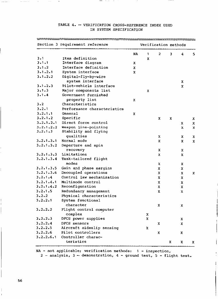
TABLE 4. - VERIFICATION CROSS-REFERENCE I N D E X USED I N SYSTEM SPECIFICATION
S e c t i o n 3 requirement r e f e r e n c e V e r i f i c a t i o n methods
3.1 3.1 .1
3.1.2.1 3.1 - 2
3.1 -2.2
3.1 e2.3 3.1 e3 3.1.4
3.2 3.2.1 3.2.1 .1 3.2.1.2 3.2.1 e2.1 3.2.1 -2.2 3.2.1 e3
3.2.1 -3.1 3.2.1 m3.2
3.2.1.3.3 3.2.1 -3.4
3.2.1 m3.5 3.2.1 -3.6 3.2.1 e4 3.2.1 e4.1 3.2.1 e4.2 3.2.1 -5 3.2.2 3.2.2.1
3.2.2.2
3.2.2.3 3.2.2.4 3.2.2.5 3.2.2.6 3.2.2.6.1
I t e m d e f i n i t i o n I n t e r f a c e diagram I n t e r f a c e d e f i n i t i o n Sys t e m i n t e r f a c e Digital-fly-by-wire
system i n t e r f a c e P i l o t - v e h i c l e i n t e r f a c e Major components l i s t Government f u r n i s h e d
p r o p e r t y l i s t Cha rac te r i s t ics Performance c h a r a c t e r i s t i c s General Specific Direct force c o n t r o l Weapon l i n e - p o i n t i n g S t a b i l i t y and f l y i n g
q u a l i t i e s N o r m a l mode Departure and s p i n
recovery L i m i t a t i o n s Task- ta i lored f l i g h t
Gain and phase margins Decoupled o p e r a t i o n s Cont ro l l a w mechanizat ion Multimode c o n t r o l Reconf igura t ion Redundancy management P h y s i c a l c h a r a c t e r i s t ics System f u n c t i o n a l
c h a r a c t e r F l i g h t c o n t r o l computer
c omp 1 e x DFCS power s u p p l i e s DFCS s e n s o r s A i r c r a f t s i d e s l i p s e n s i n g P i l o t c o n t r o l l e r s C o n t r o l l e r charac-
modes
teris t ics
NA 1 2
X X X
X 3 4
X X
X
X
X X
X X
X X
X X X X X X X
X
X X
X X
X
X X X
X X
X X
X
X X
X
X X
5
X X X
X X
X
X ~~~ ~~~~
NA - n o t a p p l i c a b l e ; v e r i f i c a t i o n methods: 1 - i n s p e c t i o n , 2 - a n a l y s i s , 3 -demons t r a t ion , 4 - ground tes t , 5 - f l i g h t test.
I 56

TABLE 4. - CONTINUED
Sec t ion 3 requirement r e f e r e n c e V e r i f i c a t i o n methods
3.2.2.6-2 3 e2.2 -6.3 3.2.2.7 3.2.2.8
3.2.2.9 3.2.2.10
3.2.2.11 3.2.2.1 2 3.2.3 3.2.3.1
3.2.3.2 3.2.4 3.2.5 3.2.6
3.2.6.1 3.2.6.2 3.2.7 3.3 3.3.1 3.3.2
3.3.2.1 3.3.2.2 3.3.2.3
3.3.2.4
3.3.2.5 3.3.3
3.3.4 3.3.5 3.3.6 3.3.6.1
3.3.6-2 3.3.6.2.1 3.3 -6.2.2
Primary c o n t r o l l e r Secondary c o n t r o l l e r T r i m DFCS c a u t i o n and warning
System weight Cont ro l led s u r f a c e ac tu-
Independent backup DFCS sof tware R e l i a b i l i t y F a i l u r e rate, loss of
c o n t r o l DFCS abort rate M a i n t a i n a b i l i t y Environmental c o n d i t i o n s Power requirements
Electrical Hydraul ic T r a n s p o r t a b i l i t y Design and c o n s t r u c t i o n P a r t s , materials, processes Electromagnet ic i n t e r f e r e n c e
and c o m p a t i b i l i t y General Design requirements I n s t a l l a t i o n and i n t e g r a t i o n
Electrical bonding r equ i r e -
Lightn ing p r o t e c t i o n Nameplates and product
marking Workmanship I n t e r c h a n g e a b i l i t y S a f e t y Sa fe ty , descending o r d e r of
Health and s a f e t y cri teria T o x i c i t y Electrical equipment
hazard
annuncia t i o n
ators
requirements
ments
precedence
NA 1 2 3 X X
X
X X
X X
X
X X X
X X X
X X
X X X
X
X X X
X
4 5 X X X
X X
X
X X X X
X X
X
X X
NA - n o t app l i cab le ; v e r i f i c a t i o n methods: 1 - i n s p e c t i o n , 2 - a n a l y s i s , 3 - demonst ra t ion , 4 - ground test , 5 - f l i g h t test.
57

TABLE 4. - CONCLUDED
S e c t i o n 3 requirement r e f e r e n c e V e r i f i c a t i o n methods
NA 1 2 3 4 5 3.3.6.2.3 Personnel hazard and
3.3.7 Human performance and human
3.4 Documentation X
3.6 Precedence X 3.6.1 Precedence of documents X 3.6.2 Appl ica t ion of pr ior q u a l i t y X
s a f e t y X
e n g i n e e r i n g X
3.5 Logis t i c s X
NA - n o t a p p l i c a b l e ; v e r i f i c a t i o n methods: 1 - i n s p e c t i o n , 2 - a n a l y s i s , 3 - demonstrat ion, 4 - ground tes t , 5 - f l i g h t test.
TABLE 5. - ANALOG AND DISCRETE INPUTS AND OUTPUTS
i Analog i n p u t s I
1 Azimuth error Azimuth error ra te B e t a a f t B e t a d e l t a p r e s s u r e B e t a f o r e Data age Demodulated l e f t canard p o s i t i o n Demodulated l e f t f l a p e r o n p o s i t i o n Demodulated l e f t h o r i z o n t a l
Demodulated r i g h t canard p o s i t i o n Demodulated r i g h t f l a p e r o n p o s i t i o n Demodulated r i g h t h o r i z o n t a l
t a i l p o s i t i o n Demodulated rudder p o s i t i o n E l e v a t i o n error E l e v a t i o n error rate Impact p r e s s u r e ( Qc
t a i l p o s i t i o n
L e f t a n g l e of a t t a c k L e f t canard p o s i t i o n L e f t f l aperon p o s i t i o n I L e f t h o r i z o n t a l t a i l p o s i t i o n L e f t main landing g e a r tachometer N o r m a l accelerometer P i t c h rate gyro P i t c h rate gyro speed d e t e c t P i t c h s t i c k command P i t c h s t i c k f o u r t h t r a n s d u c e r Redundancy management t e s t i n p u t Right a n g l e of a t t a c k Right canard p o s i t i o n Right f laperon p o s i t i o n R i g h t h o r i z o n t a l t a i 1 p o s i t i o n Right main landing g e a r tachometer R o l l r a te a m p l i f i e d R o l l rate gyro
I
1 I 1 1 I n d i c a t e d side-mounted angle of a t t a c k R o l l ra te gyro speed detect
La tera 1 accelerometer R o l l s t i c k command Leading edge f l a p p o s i t i o n Roll s t i c k f o u r t h t r a n s d u c e r Leading edge f l a p tachometer no. 1 Rudder p e d a l command I
I
1 Leading edge f l a p tachometer no. 2 Rudder p e d a l f o u r t h t r a n s d u c e r
58
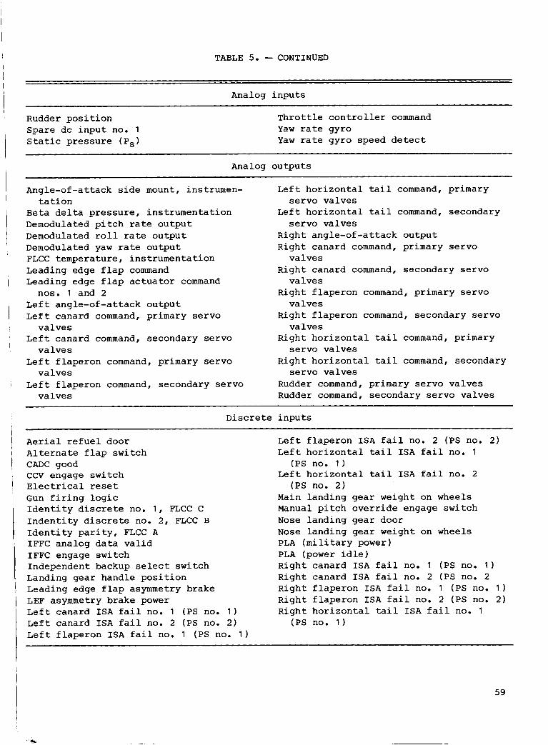
TABLE 5. - CONTINUED
I I
Analog i n p u t s I Rudder p o s i t i o n Spare dc i n p u t no. 1 Sta t i c p r e s s u r e (PSI
T h r o t t l e c o n t r o l l e r command Yaw rate gyro Yaw ra te gy ro speed d e t e c t
Analog ou tpu t s
Angle-of-attack side mount, instrumen-
B e t a d e l t a p r e s s u r e , i n s t rumen ta t ion Demodulated p i tch ra te o u t p u t Demodulated r o l l rate o u t p u t Demodulated yaw rate o u t p u t FLCC tempera ture , i n s t r u m e n t a t i o n Leading edge f l a p command Leading edge f l a p a c t u a t o r command
L e f t angle-of -a t tack o u t p u t L e f t canard command, primary s e r v o
L e f t canard command, secondary s e r v o
L e f t f l a p e r o n command, primary s e r v o
t a t i o n
nos. 1 and 2
v a l v e s
v a l v e s
v a l v e s
L e f t h o r i z o n t a l t a i l command, pr imary
L e f t h o r i z o n t a l t a i l command, secondary
Right angle-of -a t tack o u t p u t Right canard command, primary s e r v o
R igh t canard command, secondary s e r v o
Right f l a p e r o n command, primary s e r v o
Right f l a p e r o n command, secondary s e r v o
Right h o r i z o n t a l t a i l command, pr imary
Right h o r i z o n t a l t a i l command, secondary
s e r v o va lves
s e r v o va lves
va lves
va lves
va lves
va lves
s e r v o va lves
s e r v o va lves L e f t f l a p e r o n command, secondary s e r v o Rudder command, primary s e r v o v a l v e s
v a l v e s Rudder command, secondary s e r v o va lves
Discrete i n p u t s
A e r i a l r e f u e l door A l t e r n a t e f l a p swi t ch CADC good CCV engage s w i t c h Electr ical reset Gun f i r i n g l o g i c I d e n t i t y d i s c r e t e no. 1 , FLCC C I n d e n t i t y discrete no. 2 , FLCC B I d e n t i t y p a r i t y , FLCC A IFFC ana log d a t a v a l i d IFFC engage swi tch Independent backup select swi t ch Landing gea r handle p o s i t i o n Leading edge f l a p asymmetry brake LEF asymmetry brake power L e f t canard I S A f a i l no. 1 (PS no. 1 ) L e f t canard I S A f a i l no. 2 (PS no. 2 ) L e f t f l a p e r o n I S A f a i l no. 1 (PS no. 1 )
L e f t f l a p e r o n ISA f a i l no. 2 (PS no. 2 ) L e f t h o r i z o n t a l t a i l I S A f a i l no. 1
L e f t h o r i z o n t a l t a i l I S A f a i l no. 2
Main l and ing gear weight on wheels Manual p i t c h o v e r r i d e engage swi t ch Nose l and ing g e a r door Nose l and ing gea r weight on wheels PLA ( m i l i t a r y power) PLA (power i d l e ) R igh t canard ISA f a i l no. 1 (PS no. 1 ) Right canard ISA f a i l no. 2 (PS no. 2 Righ t f l a p e r o n ISA f a i l no. 1 (PS no. 1 ) Righ t f l a p e r o n I S A f a i l no. 2 (PS no. 2) Right h o r i z o n t a l t a i l I S A f a i l no. 1
(PS no. 1 )
(PS no. 2 )
(PS no. 1 )
59

TABLE 5. - CONCLUDED
Discrete i n p u t s
Right h o r i z o n t a l t a i l I S A f a i l no.
Rudder I S A f a i l no. 1 (PS no. 1 ) Rudder I S A f a i l N o . 2 (PS no. 2 ) Servo reset Speed brake extend Speed brake retract S t i c k t r i m select swi tch Trim l e f t wing down p a n e l
(PS no. 2 ) 2 Trim l e f t wing down s t i c k
Trim nose down p a n e l T r i m nose down s t i c k Trim nose l e f t p a n e l Trim nose r i g h t pane l Trim nose up p a n e l T r i m nose up s t i c k Trim r i g h t wing down p a n e l T r i m r i g h t wing down s t i c k
Discrete o u t p u t s
Analog tes t CADC reset CADC test Dual DFCS f a i L no. 1 ( h i g h ) Dual DFCS f a i l no. 2 ( h i g h ) DFCS f a i l ( h i g h ) DFCS ready IBU engage I n p u t discrete BIT tes t one I n p u t discrete B I T tes t z e r o ISA reset ( h i g h ) I S A reset ( l o w ) Lateral accelerometer torque LEF lock no. 1 LEF lock no. 2 L e f t canard c e n t e r i n g ( h i g h ) L e f t canard c e n t e r i n g ( l o w ) LHT c e n t e r i n g ( h i g h )
LHT c e n t e r i n g ( l o w ) LFLAP c e n t e r i n g ( h i g h ) LFLAP c e n t e r i n g ( l o w ) N o r m a l accelerometer torque P i t c h rate gyro torque P S A tes t P S A tes t enable Right f l a p c e n t e r i n g ( h i g h ) Right f l a p c e n t e r i n g ( l o w ) RHT c e n t e r i n g ( h i g h ) RHT c e n t e r i n g ( l o w ) Right canard c e n t e r i n g ( h i g h ) Right canard c e n t e r i n g ( l o w ) R o l l rate gyro t o r q u e Rudder c e n t e r i n g ( h i g h ) Rudder c e n t e r i n g ( l o w ) S t a 11 warning Yaw rate gyro torque
60
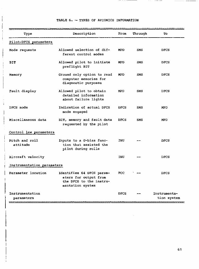
TABLE 6. - TYPES OF AVIONICS INFORMATION
Type Desc r ip t ion From Through To
Pilot-DFCS parameters
Mode r e q u e s t s
B I T
Memory
F a u l t d i s p l a y
DFCS mode
Miscel laneous
Allowed s e l e c t i o n of d i f - f e r e n t c o n t r o l modes
Allowed p i lo t to i n i t i a t e p r e f l i g h t BIT
Ground only o p t i o n t o read computer memories f o r d i a g n o s t i c purposes
Allowed p i l o t t o o b t a i n d e t a i l e d informat ion abou t f a i l u r e l i g h t s
I n d i c a t i o n of a c t u a l DFCS mode engaged
d a t a BIT, memory and f a u l t d a t a r eques t ed by t h e p i l o t
C o n t r o l l a w parameters
P i t c h and r o l l Inpu t s t o a G-bias func- a t t i t u d e t i o n t h a t a s s i s t e d t h e
p i l o t du r ing rol ls
A i r c r a f t v e l o c i t y
Ins t rumenta t ion parameters
Parameter l o c a t i o n I d e n t i f i e s 64 DFCS param- eters f o r o u t p u t from t h e DFCS to t h e i n s t r u - mentat ion system
Ins t rumen ta t ion parameters
MPD SMS DFCS
MPD SMS DFCS
MPD SMS DFCS
MPD SMS DFCS
DFCS
DFCS
SMS
SMS
I N U --
I N U --
FCC --
MPD
MPD
DFCS
DFCS
DFCS
DFCS -- I n s trumenta- t i o n system
61
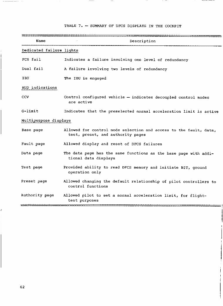
I TABLE 7. - SUMMARY OF DFCS DISPLAYS I N THE COCKPIT
N a m e D e s c r i p t i o n
Dedicated f a i l u r e l i g h t s
FCS f a i l I n d i c a t e s a f a i l u r e i n v o l v i n g one l e v e l of redundancy
Dual f a i l A f a i l u r e i n v o l v i n g two l e v e l s of redundancy
I BU The IBU i s engaged
HUD i n d i c a t i o n s
ccv Cont ro l conf igured v e h i c l e - i n d i c a t e s decoupled c o n t r o l modes are a c t i v e
G - l i m i t I n d i c a t e s t h a t t h e p r e s e l e c t e d normal a c c e l e r a t i o n l i m i t i s a c t i v e
Mult ipurpose d i s p l a y s
B a s e page Allowed €or c o n t r o l mode selection and access to the fault, data , t e s t , preset, and a u t h o r i t y pages
F a u l t page Allowed d i s p l a y and reset of DFCS f a i l u r e s
Data page The d a t a page has t h e same f u n c t i o n s as t h e base page wi th addi- t i o n a l d a t a d i s p l a y s
Te s t page Provided a b i l i t y t o read DFCS memory and i n i t i a t e BIT, ground o p e r a t i o n o n l y
P r e s e t page Allowed changing t h e d e f a u l t r e l a t i o n s h i p of p i l o t c o n t r o l l e r s t o c o n t r o l f u n c t i o n s
A u t h o r i t y page Allowed p i l o t t o set a normal a c c e l e r a t i o n l i m i t , fo r f l i g h t - t e s t purposes
62

I
TABLE 8. -MNEMONICS FOR MJ?Da
Level Type C l a s s
Recon A l l IBU 1 s t P i t c h A c t u a tor 2nd R o l l Branch Lock Yaw o u t p u t A/B LHT Compute A RHT Inpu t B L FLP "Blank 'I Center R FLP "Blank" L CND
R CND Rudder LEF A i r d a t a Switch 'I Blank"
I
Level
aLevel , type , and class are d e f i n e d i n t a b l e 9.
TABLE 9. -DESCRIPTION OF FAULT MNEMONICS
1st 2nd Recon
Lock A B
Center A/B
A 1st f a i l u r e of a p a r t i c u l a r t ype and class has occurred A 2nd l i k e f a i l u r e of a p a r t i c u l a r t ype and class has occurred Con t ro l l a w r econf igu ra t ion ( r econ) has occurred; w i l l on ly appear i f a 2nd
The l ead ing edge f l a p s are locked The secondary hydrau l i c system has f a i l e d The pr imary h y d r a u l i c system has f a i l e d A 2nd l i k e h y d r a u l i c f a i l u r e has occurred The d i sp layed c o n t r o l s u r f a c e has been cen te red
l i k e f a i l u r e of a p a r t i c u l a r t ype and class c a n ' t be i s o l a t e d
A l l P i t c h P i t c h a x i s i n p u t s have f a i l e d Roll Rol l a x i s i n p u t s have f a i l e d Yaw Yaw a x i s i n p u t s have f a i l e d LHT L e f t h o r i z o n t a l tai l RHT Right h o r i z o n t a l t a i l LFLP L e f t t r a i l i n g edge f l a p
A l l i n p u t s o r o u t p u t s of a particular class are a f f e c t e d
63
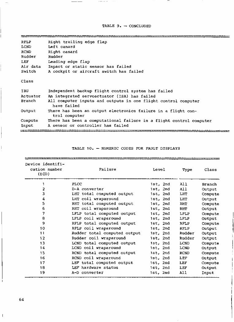
~ ~
TABLE 9. - CONCLUDED
RFLP LCND RCND Rudder LEF A i r d a t a Switch
C l a s s
I BU Actua tor Branch
o u t p u t
Compute I n p u t
Right t r a i l i n g edge f l a p L e f t canard Right canard Rudder Leading edge f l a p Impact or s ta t ic s e n s o r has f a i l ed A c o c k p i t or a i r c r a f t s w i t c h h a s f a i l e d
Independent backup f l i g h t c o n t r o l system h a s f a i l e d An i n t e g r a t e d s e r v o a c t u a t o r (ISA) h a s f a i l e d A l l computer i n p u t s and o u t p u t s i n one f l i g h t c o n t r o l computer
There h a s been a n o u t p u t e l e c t r o n i c s f a i l u r e i n a f l i g h t con-
There h a s been a computat ional f a i l u r e i n a f l i g h t c o n t r o l computer A s e n s o r or c o n t r o l l e r h a s f a i l e d
have f a i l e d
t r o l computer
TABLE 10. -NUMERIC CODES FOR FAULT DISPLAYS
Device i d e n t i f i- c a t i o n number
( D I D ) F a i l u r e
~~
L e ve 1 Type C l a s s
1 2 3 4 5 6 7 8 9
10 1 1 12 1 3 14 15 16 17 18 19
FLCC ls t , 2nd D-A c o n v e r t e r l s t , 2nd LHT to t a l computed o u t p u t l s t , 2nd LHT co i l wraparound ls t , 2nd RHT t o t a l computed o u t p u t l s t , 2nd RHT c o i l wraparound lst, 2nd LFLP t o t a l computed o u t p u t l s t , 2nd LFLP c o i l wraparound ls t , 2nd RFLP to t a 1 computed o u t p u t lst, 2nd RFLP co i l wraparound ls t , 2nd Rudder t o t a l computed o u t p u t l s t , 2nd Rudder c o i l wraparound ls t , 2nd LCND t o t a l computed o u t p u t lst , 2nd LCND c o i l wraparound lst, 2nd RCND t o t a l computed o u t p u t lst , 2nd RCND c o i l wraparound ls t , 2nd LEF to t a l computed o u t p u t lst , 2nd LEF hardware s t a t u s l s t , 2nd A-D c o n v e r t e r l s t , 2nd
A 1 1 A 1 1 LHT LHT RHT RHT LFLP LFLP RFLP RFLP Rudder Rudder LCND LCND RCND LEF LEF LEF A 1 1
Branch o u t p u t Compute o u t p u t Compute o u t p u t Compute o u t p u t Compute o u t p u t o u t p u t ou tpu t
o u t p u t
o u t p u t
o u t p u t
Compute
Compute
Compute
I n p u t
64

TABLE 10. - CONCLUDED
Device i d e n t i f i-
(DID) cat ion number F a i l u r e Le ve 1 Type C l a s s
20
21
22 23
24
25
26 27 2 8 29 30 31
32
33
34 35
36 37 38 39
40
41
42
43
44
45
46
800-Hz power supply
P i t c h rate senso r ( i n v e r t e r )
Spare R o l l rate s e n s o r
Yaw rate s e n s o r
Angle-of-attack s e n s o r
Spare LEF pot wraparound P i t c h s t i c k R o l l s t i c k Rudder p e d a l T h r o t t l e t w i s t
N o r m a l a c c e l e r a t i o n s e n s o r
Lateral d i r e c t i o n a l accel- e ra t ion s e n s o r
Spare S ta t ic or impact
Discrete IOC Discretes I B U p i t c h wraparound I B U la teral d i r e c t i o n a l
LHT ISA p r e s s u r e
RHT ISA p r e s s u r e
s e n s o r p r e s s u r e
wraparound
system
s y s tern
s y s tern
s y s t e m
s y s tern
s y s tern
system
LFLAP I S A pressure
RFLAP ISA p r e s s u r e
Rudder ISA p r e s s u r e
LCND ISA p r e s s u r e
R ~ D ISA p r e s s u r e
l s t , 2nd
l s t , 2nd recon
lst , 2nd recon
lst, 2nd recon
lst, 2nd recon
1 s t l s t , 2nd lst , 2nd ls t , 2nd l s t , 2nd
recon lst, 2nd
recon ls t , 2nd
recon
ls t , 2nd recon
lst , 2nd ls t , 2nd ls t , 2nd ls t , 2nd
A, B, A-B, c e n t e r
A, B, A-B, c e n t e r
A, B, A-B, c e n t e r
c e n t e r
c e n t e r
c e n t e r
c e n t e r
A, B, A-B,
A, B, A-B,
A , B, A-B,
A, B, A-B,
A 1 1
P i t c h
R o l l
Yaw
P i t c h
P i t c h P i t c h R o l l Yaw P i t c h
P i t c h
Yaw
Air d a t a Switch Switch P i t c h Roll
LHT
RHT
LFLP
RFLP
Rudder
LCND
RCND
Inpu t
I n p u t
I n p u t
I n p u t
I n p u t
I n p u t I n p u t I n p u t I n p u t I n p u t
I n p u t
I n p u t
I n p u t
I n p u t I n p u t I BU I BU
Actua tor
Actua tor
Actuator
Actua tor
Actuator
Actuator
Actuator
65

TABLE 1 1 . - DISCRETE INPUTS PROCESSED BY THE DISCRETE SELECTOR-MONITOR
Descript ion
Group 1 : Requires 5 msec s e t t l i n g t i m e
Nose landing gear door Landing gear handle Right h o r i z o n t a l t a i l PS no. 1 Right h o r i z o n t a l t a i l PS no. 2 S t i c k t r i m r i g h t wing down CADC v a l i d L e f t f l a p PS no. 1 L e f t f l a p PS no. 2 Rudder PS no. 1 Rudder PS no. 2 R i g h t canard PS no. 1 Gun f i r i n g CCV engage R i g h t canard PS no. 2 IFFC engage IBU select A l t e r n a t e f l a p swi tch L e f t h o r i z o n t a l t a i l PS no. 1 LEF assymetry brake
P i t c h i n t e g r a t o r i n h i b i t Right f l a p PS no. 1 Right f l a p PS no. 2 Speed break re t ract A i r r e f u e l door open LEF brake power PLA i d l e S t i c k t r i m l e f t wing down S t i c k t r i m nose up Speed break extend S t i c k t r i m nose down Weight on nose landing gear PLA a t m i l i t a r y power LARAP engage r e q u e s t LARAP disengage request Left h o r i z o n t a l t a i l PS no. 2 L e f t canard PS no. 1 L e f t canard PS no. 2 IFFC good
Group 2: Requires 80 msec s e t t l i n g t i m e
E lec t r ica l reset Panel t r i m nose down Servo reset Panel t r i m nose l e f t Pane l t r i m nose up Panel t r i m nose r i g h t Manual p i t c h override engage S t i c k t r i m d i s c o n n e c t Panel t r i m l e f t wing down weight on main l a n d i n g g e a r Panel t r i m r i g h t wing down
66

p: 0 H H z 0
p: 0 I3 u w 4 w rn w X H *
F
m n w rn rn w u 0 l3
w rn H 3 PI
u 2 3 I . (v
w v-
lil E5
I L.4
' m I u n
I C 4 5 al r n w a l
a l m k -
VI r
IC
IC
4 ZICICICICICIC
2ICICICICICIC
4 4 4 Z Z P Z
IC IC IC IC
m m m r m m m m m m
c 0
m a a l al 4J 4J 4
w 0 al d b c 4
al 4J a k
d d 0 p:
m v v m v
4 J m m
. P c -d k 0
a l p ) @ a , a l a , a l a l 4 J 4 J 4 J 4 J 4 J 4 J 4 J 4 J 0 0 0 0 0 0 0 0 z z z z z z z z
4J 7 2 5 .d
k 5 0 W
4
k 0 Iw
P c 4 k 0 4J .d c 0 E
al z d d a
67

68
TABLE 13. - HIERARCHICAL STRUCTURE OF SYSTEM USED BY FAILURE MANAGER
~~ ~ ~ ~ ~~~~
1 FLCC ( f l i g h t c o n t r o l computer) 1 .l Dig i ta l - to-ana log (D-A) c o n v e r t e r
1 .l .l L e f t h o r i z o n t a l t a i l c o i l wraparound 1.1.2 Right h o r i z o n t a l t a i l c o i l wraparound 1.1.3 L e f t f l a p c o i l wraparound 1.1.4 Right f l ap c o i l wraparound 1.1.5 Rudder c o i l wraparound 1.1.6 L e f t canard co i l wraparound 1.1.7 Right canard c o i l wraparound 1.1.8 Leading edge f l ap (LEF) t o t a l computed o u t p u t (TCO)
1 . 1.8 . 1 LEF hardware 1.2 L e f t h o r i z o n t a l t a i l TCO 1.3 Right h o r i z o n t a l t a i l TCO 1.4 L e f t f l ap TCO 1.5 Right f l a p TCO 1.6 Rudder TCO 1.7 L e f t canard TCO 1.8 Right canard TCO
2 Analog-to-digi ta l (A-D) c o n v e r t e r 2.1 I n v e r t e r (800-Hz power supply)
2.1.1 P i t c h rate s e n s o r 2.1.2 R o l l r a te sensor (normal or a m p l i f i e d ) 2.1.3 Yaw rate sensor 2.1.4 Angle-of-attack sensor 2.1.5 Beta (yaw) s e n s o r ( a t p r e s e n t n o t monitored) 2.1.6 LEF pot wraparound 2.1.7 P i t c h s t i c k 2.1 .% R o l l s t i c k 2.1.9 Rudder pedal 2.1 . l 0 T h r o t t l e t w i s t
2.2 N o r m a l a c c e l e r a t i o n sensor 2.3 Lateral d i rec t iona l a c c e l e r a t i o n s e n s o r 2.4 Impact p r e s s u r e (Qc) s e n s o r or s t a t i c p r e s s u r e (P,) sensor
3 Discrete IOC 3.1 I n d i v i d u a l d i s c r e t e s ( s w i t c h e s )
I B U p i t c h wraparound I B U l a t e ra l d i r e c t i o n a l wraparound L e f t h o r i z o n t a l t a i l ISA Right h o r i z o n t a l t a i l ISA L e f t f l ap ISA Right f l a p ISA Rudder ISA L e f t canard ISA Right canard ISA
I

TABLE 14. - SOFTWARE MECHANIZATION FOR GOOD-CHANNEL-AVERAGE SELECTOR MONITOR, NO PRIOR FAILURES
Values F a i l u r e c o n d i t i o n s
ABS (L-S) > E N N Y Y Y N N Y Y Y
ABS (S-R) > E N Y N N N Y Y Y Y Y
ABS (L-R) > E - N N Y Y Y Y N N Y LPC = f i r s t f a i l l imi t -1 - - - N Y - - - - - SPC = f i rs t f a i l l imit-1 - - - - - - - N Y -
RPC = first f a i l l imi t -1 - - - - - N Y - - -
Required act ion 1 2 2 3 4 5 6 7 8 9
Act ions :
1 .
2.
3.
4.
5.
Decrement LPC i f LPC > 0 SPC i f SPC > 0 RPC i f RPC > 0 6.
S e l e c t ( L + S + R)/3
S e l e c t (L + S + R ) / 3
Decrement SPC i f SPC > 0
Increment LPC and TPC S e l e c t (S + R)/2
RPC i f RPC > 0 7.
Decrement SPC i f SPC > 0
Increment LPC and TPC Invoke f a i l u r e manager S e l e c t based on DST M S
RPC i f RPC > 0 8.
Decrement LPC i f LPC > 0
Increment RPC and TPC SPC i f SPC > 0 9.
N o t e s :
Decrement LPC i f LPC > 0 SPC i f SPC > 0
Increment RPC and TPC Invoke f a i l u r e manager S e l e c t based on DST M S
Decrement LPC i f LPC > 0 RPC i f RPC > 0
Increment SPC and TPC S e l e c t (L + R)/2
Decrement LPC i f LPC > 0 RPC i f RPC > 0
Increment SPC and TPC Invoke f a i l u r e manager S e l e c t based on DST M S
Increment TPC S e l e c t ( L + S + R ) / 3
I n a l l cases the s e l e c t e d o u t p u t is 0 i f t h e r e c o n f i g u r a t i o n f l ag (RECF) i s set.
L l e f t XPC persis t ance coun te r s , number of i t e ra t ions S self a f a i l u r e has been present, where X is L, R r i g h t S, R, or T T t o t a l E f a u l t d e t e c t i o n l e v e l
ABS a b s o l u t e value DST d e v i c e s t a t u s t a b l e MS monitor s ta te
69

TABLE 15. - VERIFICATION TEST PLAN SUMMARY
S e c t i o n
1 Purpose
2 Applicable documents 2.1 Government documents 2.2 Nongovernment documents
3 T e s t concepts 3.1 D e f i n i t i o n of terms 3.2 Descr ip t ion of program under t e s t
3.2.1 System operational c h a r a c t e r i s t i c s 3.2.2 DFCS OFP f u n c t i o n s
3.3 T e s t phi losophy
4 Qualif i c a i t o n requirements and cri teria 4.1 Stand-alone t e s t i n g
4.1.1 AMUX d a t a i n t e r f a c e t e s t 4.1.2 Gain scheduler tes t 4.1.3 Control l a w f requency response tes t 4.1.4 Cont ro l mode selection and t r a n s i t i o n response test 4.1.5 Analog i n p u t S/M operation test 4.1.6 Discrete i n p u t S/M o p e r a t i o n 4.1.7 ISA monitor o p e r a t i o n t e s t 4.1.8 LEF monitor o p e r a t i o n t e s t 4.1.9 Long power outage test 4.1.10 S h o r t power outage test 4.1.1 1 Memory and d u t y c y c l e r e s e r v e tes t 4.1 .12 B u i l t - i n t es t 4.1 .13 F lyable hardware retest
5 T e s t 5.1 5.2 5.3 5.4 5.5 5.6 5.7 5.8
implementation Locat ion and schedule L i m i t a t i o n s and g e n e r a l comments P r e p a r a t i o n of i n p u t Conduct of tests Analysis of r e s u l t s Summary of equipment S p e c i a l t e s t sof tware Summary of p e r s o n n e l requirements
6 Cont ro l and r e p o r t i n g procedures 6.1 Conf igura t ion c o n t r o l and documentation maintenance 6.2 T e s t f a i l u r e a n a l y s i s , repair and r e t e s t i n g
7 Requirements c ross - re ference
70

TABLE 16. - REVERIFICATION ACCEPTANCE TESTS
T e s t
Ver i fy AMUX inpu t -ou tpu t i n t e r f a c e -Static SASB c o n t r o l l a w end-to-end c a l c u l a t i o n s a t Mach 0.9, sea l e v e l - M U X input -output w o r d s
V e r i f y end-to-end c o n t r o l l a w f requency response -Discrete s i n u s o i d a l i n p u t s ( 1 , 5, and 12 Hz) f o r a l l c o n t r o l modes -P i t ch and yaw feedback senso r i n p u t s
Ver i fy mul t ip l e s i n g l e f a i l - f a u l t annunc ia t ion -Ver i fy s i n g l e f a i l dev ice s t a t u s e n t r i e s f o r a l l moni tor ing p l a n e s i n
s t a n d a r d normal mode (SNRM) f o r ana log i n p u t s , d i s c r e t e i n p u t s , a c t u a t o r i n p u t s , I S A and LEF o u t p u t s
V e r i f y f i r s t f a i l f requency response - V e r i f i e s SNRM f i r s t f a i l performance i s same as n o - f a i l performance
(repeat tes t 2 f o r SNRM)
Ver i fy s i n g l e FLCC long outage restart performance - S a t i s f a c t o r y restart performance -Proper r e c o n s t r u c t i o n of dev ice s t a t u s t a b l e f a u l t h i s t o r y from non-
v o l i t i v e memory u s i n g tes t 3 f a u l t s
Ver i fy r e s t a r t e d FLCC f requency response -Ver i fy FLCC performance una f fec t ed by a long power outage u s i n g t es t 2
f o r SNRM
V e r i f y m u l t i p l e d u a l f a i l and g r a c e f u l deg rada t ion t o one FLCC -Dual f a i l d e v i c e s t a t u s e n t r i e s and AMUX f a u l t annunc ia t ion i n a l l moni-
- I n s e r t p a r i t y e r r o r i n one FLCC t o r i n g p l a n e s
Ver i fy s i n g l e FLCC f requency response test - V e r i f i e s remaining FLCC from tes t 7 has approximate ly same performance as
nominal t r i p l e x system u s i n g tes t 2 f o r SNRM
71
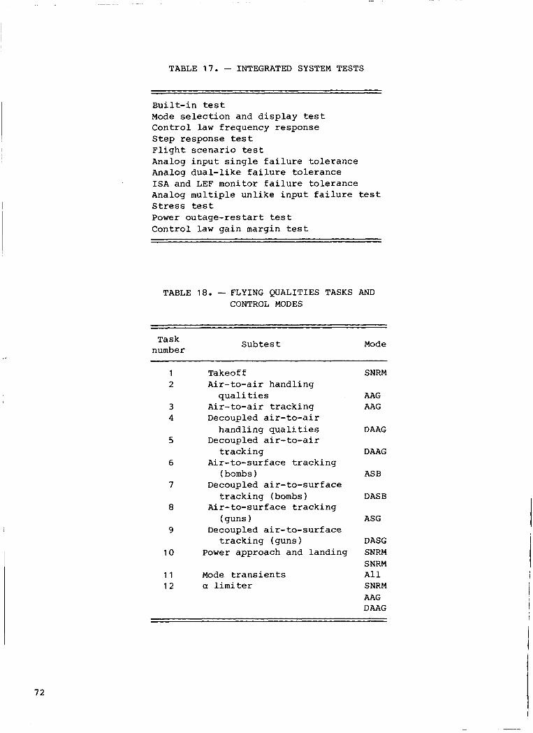
TABLE 17. - INTEGRATED SYSTEM TESTS
Bui 1 t- i n tes t Mode s e l e c t i o n and d i s p l a y t e s t Cont ro l l a w f requency response Step response t e s t F l i g h t s c e n a r i o test Analog i n p u t s i n g l e f a i l u r e t o l e r a n c e Analog d u a l - l i k e f a i l u r e t o l e r a n c e I S A and LEF monitor f a i l u r e t o l e r a n c e Analog m u l t i p l e u n l i k e i n p u t f a i l u r e t e s t S t r e s s test Power o u t a g e - r e s t a r t tes t C o n t r o l l a w g a i n margin tes t
TABLE 1 8 . - FLYING QUALITIES TASKS AND CONTROL MODES
, ”
Task number
S u b t e s t Mode
1 2
3 4
5
6
7
8
9
1 0
1 1 1 2
Takeoff A i r - to-ai r handl ing
Air-to-air t r a c k i n g Decoupled air-to-air
handl ing q u a l i t i e s Decoupled air-to-air
t r a c k i n g Air- to-surface t r a c k i n g
(bombs 1 Decoupled a i r - t o - s u r f a c e
t r a c k i n g (bombs) Air- to-surface t r a c k i n g
(guns 1 Decoupled a i r - to-sur f ace
t r a c k i n g (guns ) Power approach and landing
q u a l i t i e s
Mode t r a n s i e n t s a l i m i t e r
SNRM
AAG AAG
D AAG
DAAG
ASB
DASB
ASG
DASG SNRM SNRM A 1 1 SNRM AAG DAAG
7 2

I
~
I
j
I
I
I
i I 1 I i I
I t
,
I I
)I
I t
I
1 ~
I I I
TABLE 19. - COMPONENTS CONSIDERED I N FAILURE MODES AND EFFECTS TESTING
1 . 2 . 3. 4. 5 .
6 . 7 . 8. 9 .
10.
1 1 .
12.
13. 14. 15. 16.
Engine f a i l u r e Emergency power u n i t (EPU) f a i l u r e Main gene ra to r f a i l u r e System A h y d r a u l i c f a i l u r e Any I S A servovalve SV1 o r
System B h y d r a u l i c f a i l u r e Any I S A se rvova lve SV3 f a i l u r e ISA so leno id va lve f a i l u r e FLCC power supply f a i l u r e C e n t r a l p r o c e s s i n g u n i t
( CPU 1 f a i l u r e Input -output c o n t r o l l e r
( IOC ) f a i l u r e Analog- to-d ig i ta l (A-D) conve r t e r
f a i l u r e 800 Hz power f a i l u r e S e n s o r s - c o n t r o l l e r s E x t e r n a l 215 V dc p o w e r f a i l u r e Dig i ta l - to-ana log (D-A) con-
SV2 f a i l u r e
v e r t e r f a i l u r e
17. 18. 19. 20. 21. 22. 23 24 25.
26 27. 28 29. 30 31 32 33. 34.
I S A primary co i l s i g n a l f a i l u r e ISA secondary coi l s i g n a l f a i l u r e Leading-edge f l a p command f a i l u r e I n p u t d i s c r e t e s e c t i o n f a i l u r e System i n p u t d i s c r e t e f a i l u r e Wraparound i n p u t d i s c r e t e f a i l u r e Output d i s c r e t e s e c t i o n f a i l u r e ISA o u t p u t d i s c r e t e F a i l u r e annunc ia t ion o u t p u t d i s -
BIT o u t p u t discrete f a i l u r e D a t a l i n k transmitter f a i l u r e Data l i n k r e c e i v e r f a i l u r e Avionics m u l t i p l e x bus f a i l u r e IBU f a i l u r e LEF command s e r v o Runaway t r i m Avionics f a i l u r e s D i g i t a l va lue of a c t u a t o r commands
crete f a i l u r e
~~ ~~~~ ~~~ _____ ~~ ~
TABLE 20. - FAILURE MODES AND THEIR EFFECTS
Component F a i l u r e mode F a i l u r e effect ~~
Note: The f i r s t e i g h t components were n o t cons ide red t o be DFCS components.
9 . FLCC p o w e r Turn-of f p o w e r
supp ly Branch f a i l u r e including loss of
one set of i n p u t s , one CPU, and one set of o u t p u t s p l u s switch- i n g of one set of s e rvova lve c o i l s to t h e secondary c o i l s
10. C e n t r a l proc- H a l t CPU Branch f a i l u r e i n c l u d i n g loss of e s s i n g u n i t CPU and one set of o u t p u t s p l u s ( CPU ) swi t ch ing of one set of servo-
v a l v e c o i l s to the second- a r y coi ls
73

TABLE 20. - CONTINUED
Component F a i l u r e mode F a i l u r e e f f e c t
Input-ou t p u t c o n t r o l l e r ( I O C )
H a l t IOC Branch f a i l u r e i n c l u d i n g loss of one s e t of i n p u t s , one CPU, and one set of o u t p u t s p l u s switch- i n g of one set of se rvovalve co i l s t o t h e seccondary c o i l s
1 1 .
12.
13.
14.
15.
16.
17.
18.
19.
20.
21.
22.
Hard-over A-D i n p u t s Ripple A-D and D-A f a i l u r e trees A-D c o n v e r t e r
20 V ac 800 HZ
power Turn-off power by
p u l l i n g breaker t o a branch i n v e r t e r
Ripple t h e i n v e r t e r r e s u l t i n g i n loss of one set of 800 Hz i n p u t s
Sensor and con- t r o l l e r i n p u t s
Turn-off any s e n s o r or p i l o t c o n t r o l l e r i n p u t
L o s s of a s i n g l e i n p u t ; o t h e r t w o i n p u t s are monitored t o o b t a i n a v a l i d s i g n a l
E x t e r n a l f 1 5 V dc p o w e r
a. Ground + I 5 V d c from
b. Ground -1 5 V d c from one F'LCC
one FLCC
a. Ripple A-D f a i l u r e tree i n
b. R i p p l e A-D f a i l u r e tree i n one E'LCC
one FLCC
Hard-over D-A o u t p u t s Ripple D-A r e s u l t i n g i n loss of one set of o u t p u t s p l u s switch- i n g of one set of se rvovalve co i l s t o t h e secondary co i l s
D-A c o n v e r t e r
ISA primary c o i l
Open co i l c u r r e n t wraparound
C o i l c u r r e n t f a i l u r e ; s w i t c h to backup s e r v o a m p l i f i e r f o r d r i v - i n g secondary c o i l of one ISA
ISA secondary coi 1
Open backup c o i l cur- r e n t wraparound
Backup s e r v o amplifier f a i l u r e
LEF command Hard-over command on FLCC C
LEF o u t p u t e l e c t r o n i c f a i l u r e p l u s swi tch ing LEF d r i v e to FLCC B
IOC i n p u t dis- crete s e c t i o n
Simultaneous f a i l u r e of a l l system and wrap- around discrete i n p u t s t o no change
I n d i v i d u a l d i s c r e t e s f a i l u r e i n one FLCC each t i m e a discrete i n p u t is changed by t h e p i l o t
F a i l a l l system i n p u t discretes of one FLCC t o undriven bus
Discrete f a i l u r e r e s u l t i n g i n loss of a par t ia l set of system i n p u t d i scre tes
System i n p u t d i s c r e t e s
N o t applicable Wraparound ( w / A ) i n p u t d i s c r e t e s
Incorpora ted i n compo- n e n t no. 20

TABLE 20. - CONTINUED
~~ ~ ~~ ~ ~ ~~
Component F a i l u r e mode F a i l u r e e f f e c t
23. IOC o u t p u t d i s - Fa i l a l l BIT , ISA and Undetected f i r s t f a i l u r e Crete s e c t i o n f a i l u r e annunc ia t ion
o u t p u t d i s c r e t e s of one l?LCC t o no change
24. I S A o u t p u t Incorpora ted i n compo- Not a p p l i c a b l e d i s c r e t e s n e n t no. 23
25. F a i l u r e Incorpora ted i n compo- N o t applicable annunc ia t ion n e n t no. 23 d i s c r e tes
26. B I T o u t p u t a. Landing g e a r handle a. L a t e r a l - d i r e c t i o n a l I B U f a i l - d i s cre tes d i s c r e t e B I T in - u r e on l and ing
j ec t
i n j e c t swi t ch ing to backup coi ls b. Analog i n p u t B I T b. ‘Ripple A-D f a i l u r e tree, p l u s
hardware i n one FLCC C. IBU i n t e g r a t o r B I T C. P i t c h I B U f a i l u r e
i n j e c t
27. D a t a l i n k Open both data l i n k Branch f a i l u r e i n c l u d i n g loss of t ransmi t t e r l i n e s from FLCC B one set of i n p u t s , one CPU, and
one set of o u t p u t s p l u s switch- i n g of one set of servovalve co i l s t o t h e secondary co i l s
28. Data l i n k F a i l one r e c e i v e r of Branch f a i l u r e i n c l u d i n g loss of r e c e i v e r FLCC B to s t a t u s one s e t of i n p u t s , one CPU, and
good, d a t a bad one set of o u t p u t s p l u s switch- ing of one set of se rvova lve c o i l s t o t h e secondary co i l s
29. AMUX
30. I B U
a. S t a t u s good, d a t a a. L o s s of AMUX p l u s command t o
b. Good d a t a on bo th b. Loss of AMUX and p o s s i b l y
C. Bus c o n t e n t i o n C. I nde te rmina te , p o s s i b l e
d. Accepting any ter- d. Inde termina te , p o s s i b l e
bad on one bus ASB mode
buses one FLCC
FLCC loss
mina l addres s FLCC loss
Incorpora ted i n compo- N o t a p p l i c a b l e n e n t no. 26
31. LEF command K i l l power to one motor Lock one motor d r i v e s e r v o

TABLE 20. - CONCLUDED
Component F a i l u r e mode F a i l u r e e f f e c t
32. Runaway t r i m a. b.
d. C.
33. Avionic a. f a i l u r e s b.
34. D i g i t a l value a. of a c t u a t o r commands
N o s e-up N o s e-down Right wing down L e f t wing down
FCC f a i l SMS f a i l
R a m p on o u t p u t of s i n g l e s u r f a c e o u t p u t command, channel B
Hard-over o u t p u t of s u r f a c e o u t p u t commands by a l l computers
F a i l u r e of s t i c k t r i m swi tches
a. Force c o n t r o l of AMUX t o SMS b. Loss of MPD
a. Simulated sof tware error causes TCO miscompare
b. Simulated g e n e r i c software error r e q u i r i n g manual s e l e c t i o n of t h e I B U
TABLE 21. - REVALIDATION TESTS
T e s t
1 V e r i f y DFCS and s i m u l a t i o n i n t e r f a c e s pass p r e f l i g h t B I T 2 Ver i fy mode s e l e c t i o n and o t h e r base page o p t i o n s
-MPD mode menu and CCV swi tches -DGFT/MSOV/CCV swi tches -HUD miss ion phase mode and CCV swi tch -Optimum flap-no scheduled f l a p -Drag modulation-drag convent iona l
-Cont ro l le r i n p u t f a i l u r e s -Switch f a i l u r e s -Sensor i n p u t f a i l u r e s ( f i r s t and second l i k e )
-Prese lec ted pedal , s t i c k , t h r o t t l e o p t i o n s f o r decoupled ASG modes -Mode o p t i o n c h a n g e a b i l i t y
-Landing g e a r up-down -Panel t r i m -Nose g e a r door open-closed -S t ick t r i m
6 V a l i d a t e take-off and landing performance -Stores-clean ( s t a n d a r d normal) -P i tch ra te r e c o n f i g u r a t i o n ( l a n d i n g o n l y ) -Standby g a i n s ( l a n d i n g o n l y ) -1BU ( l a n d i n g o n l y )
-Coupled maximum s t ick- rudder p e d a l - t h r o t t l e t w i s t commands ( se lec t modes) -Maximum a l t i t u d e - s p e e d loops ( a l l modes)
- F l a t t u r n d e c o u p l e d - f l a t t u r n coupled 3 V e r i f y f a u l t annuncia t ion of DFCS i n p u t s
4 V e r i f y preset decoupled o p t i o n s
5 Ver i fy p i l o t i n p u t d i s c r e t e
7 High-performance maneuvers
76
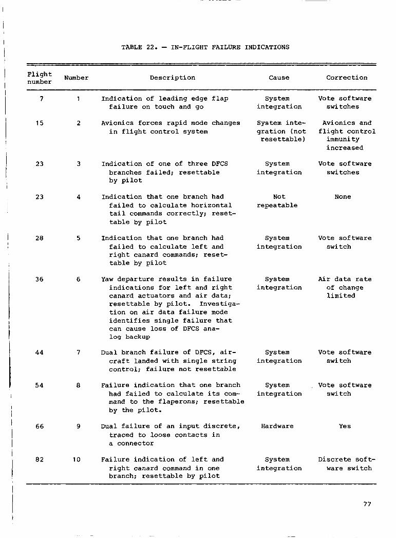
TABLE 22. - IN-FLIGHT FAILURE INDICATIONS
F1i gh Number number Desc r ip t ion Cor rec t ion Cause
7
15
23
23
28
36
44
54
66
82
1
2
3
4
5
6
7
8
9
10
I n d i c a t i o n of l e a d i n g edge f l a p f a i l u r e on touch and go
System i n t e g r a t i o n
Vote so f tware swi t ches
Avionics f o r c e s r a p i d mode changes i n f l i g h t c o n t r o l system
System i n t e - g r a t i o n ( n o t rese t t a b l e )
Avionics and f l i g h t c o n t r o l
immunity i n c r e a s e d
I n d i c a t i o n of one of t h r e e DFCS branches f a i l e d ; r e s e t t a b l e by p i l o t
Sys t e m i n t e g r a t i o n
Vote so f tware swi t ches
I n d i c a t i o n t h a t one branch had f a i l e d to c a l c u l a t e h o r i z o n t a l t a i l commands c o r r e c t l y ; reset- t a b l e by p i l o t
N o t repea t a b l e
None
Sys t e m V o t e so f tware i n t e g r a t i o n swi t ch
I n d i c a t i o n t h a t one branch had f a i l e d to c a l c u l a t e l e f t and r i g h t canard commands; reset- table by p i l o t
System i n t e g r a t i o n
Air data rate of change l i m i t e d
Yaw d e p a r t u r e r e s u l t s i n f a i l u r e i n d i c a t i o n s f o r l e f t and r i g h t canard a c t u a t o r s and a i r da t a ; resettable by p i l o t . Inves t iga - t i o n on a i r d a t a f a i l u r e mode i d e n t i f i e s s i n g l e f a i l u r e t h a t can cause l o s s of DFCS ana- log backup
Dual branch f a i l u r e of DFCS, air- c r a f t landed wi th s i n g l e s t r i n g c o n t r o l ; f a i l u r e n o t resettable
Sys t e m i n t e g r a t i o n
Vote so f tware swi t ch
F a i l u r e i n d i c a t i o n t h a t one branch had f a i l e d to c a l c u l a t e i t s com- mand to the f l ape rons ; resettable by the pi lot .
Sys t e m i n t e g r a t i o n
Vote so f tware swi tch
Dual f a i l u r e of an i n p u t d i s c r e t e , t r a c e d to loose c o n t a c t s i n a connector
Hardware Y e s
F a i l u r e i n d i c a t i o n of l e f t and r i g h t canard command i n one branch; r e s e t t a b l e by p i l o t
Discrete s o f t - ware swi t ch
Sys t e m i n t e g r a t i o n
77

TABLE 22. - CONCLUDED
Number D e s c r i p t i o n Cause C o r r e c t i o n F l i g h t number
85
91
~~~ ~~~~
1 1 I n d i c a t i o n of one of t h r e e Sys tern V o t e sof tware DFCS branches f a i l e d ; i n t e g r a t i o n swi tch r e s e t t a b l e by p i l o t
12 I n d i c a t i o n of one of t h r e e DFCS branches f a i l e d ; re- s e t t a b l e by p i lo t ; occurred d u r i n g a i r c r a f t r e f u e l i n g
Various f l i g h t s 13 F a i l u r e i n d i c a t i o n s t h a t an ~ from f l i g h t 72 i n p u t d i s c r e t e had f a i l e d ;
t o f l i g h t 100 rese t tab le by p i l o t ; occur red f i v e t i m e s
Various f l i g h t s 14 F a i l u r e i n d i c a t i o n t h a t I a n i n p u t swi tch faded,
occur red upon a c t i v a t i o n of a c o c k p i t switch; reset- table by p i l o t ; occurred many t i m e s
Unknown
Unknown
Switch des ign
None
None
None
None 95 15 F a i l u r e i n d i c a t i o n of angle- D i s s i m i l i a r o f - a t t a c k s e n s o r a f t e r angle-of - f l y i n g through wake of a t t a c k s e n s o r s a n o t h e r a i r c ra f t ; reset- table by p i l o t
TABLE 23. - B I T DETECTED FAILURES OF HARDWARE AND SOFTWARE
Number D e s c r i p t i o n
1 BIT d e t e c t e d a f a u l t y r e l a y used i n swi tch ing commands to t h e l e a d i n g
2 BIT detected f a i l u r e s of semiconductor random access memory a t approximately
3 BIT d e t e c t e d f a i l u r e of a semiconductor d i s c r e t e d r i v e used i n l o g i c t h a t
4 BIT detected a f a i l u r e of a h y d r a u l i c a c t u a t o r 5 B I T d e t e c t e d a p a r i t y error and would n o t f i n i s h BIT test; t h e p a r i t y
e r r o r i n d i c a t i o n r e s u l t e d from a sof tware error i n t h e B I T test for p a r i t y errors
edge f l a p s
40°F
d e t e c t s second f a i l u r e s of t h e computers

TABLE 24. - UNRESOLVED B I T FAILURE INDICATIONS
Number Desc r ip t ion
1 One of the t h r e e computers f a i l e d du r ing BIT; s u s p e c t cause was loss of
2 B I T f a i l e d numerous times whi le t e s t i n g va r ious DFCS components; EM1 w a s power t o channe 1
be l i eved t o be t h e cause
TABLE 25. - B I T FAILURES DUE TO SYSTEMS INTEGRATION
Number Desc r ip t ion ~
1 After tests t o check b a t t e r y p o w e r t o t h e DFCS, BIT would d e t e c t f a i l u r e s of a l l i n p u t s e n s o r s
2 B I T so f tware w a s unable to use back-up a v i o n i c s bus i n t h e e v e n t of a f a i l - u re ; r e s u l t e d i n p i l o t unable t o monitor or o p e r a t e BIT; system locked up
3 Accidenta l 2nd a c t i v a t i o n of B I T f a i l e d because of an unknown t iming con- s t r a i n t f o r BIT ope ra t ions
4 B I T d e t e c t s l ead ing edge f l a p lock and i n p u t f a i l u r e s because of improper procedures
5 B I T i n d i c a t e d f a i l u r e s because of no i se induced from running a c t u a t o r tests, numerous accounts
6 A procedure e r r o r causes BIT t o be run wi th f a i l u r e s p r e s e n t ; r e s u l t e d i n B I T locking up
7 B I T f a i l s to d e t e c t a f a u l t i n t h e IBU a f t e r a mod i f i ca t ion to t h e IBU w a s made; hardware mod i f i ca t ion d i d n o t have corresponding change i n BIT t es t
TABLE 26. -ANOMALIES WITH MEMORY MODE OPERATION
1 . One of t h r e e computers f a i l e d because of e n t e r i n g memory mode wi th c o n t r o l i n -
2. Engine s t a r t i n the memory mode caused complete DFCS f a i l u r e and hard-over ca- p u t s ; f a u l t d e t e c t i o n upon e x i t of memory mode causes i n t e r c h a n n e l d i f f e r e n c e s
na rds to impinge on nose wheel door
79

a VI
6 3
3
H cn
h I: 3 5
z cn cn 2
0,
F 0
z H u z 3 F
4
2 cn h z w H
5 w & 3 d 2
i z >( a 0
4 I . r- N
w I4 a 2
d 0
4J .4 [I) 0 a $* k a, 3 0 V a, k
E 0 k W
$* a 5 a, 3
r- r- .
02 N
m m .
b P
0
m m 0 .
m m 0 .
4J W
m o 0 0
0 0
N
L
x o '
k .4 a 0 4J
k 4
r- b .
m m
* .3 .
F r- 0 .
m m 0 .
m m 0 .
4J .w tD .O 0 0 0
"Ln'
a, V a
W k 5 [I)
0 4J
k -4 4
w 3 ;17 2
2 z w u g o 3 H cnB
4 Glu O H & F B H z u o w uPl cn
cnz o w PlH ocn
8 B
q I B . co N
w 4 4 h a
m m o m r - 0 F c
m m m m m m m m m c n m m 0 0 0 0 0 0
e . . . . .
ai 3 0 0 3 0 0 a , o o o ) o o d O O d 0 0
c - - - a o o a o o a , - * a I r w cn cn
8 0

Figure 1. The AFTI F16 airplane.
Flight control panel switches Caution, warning, and stick_/ trim : y r t rlrl advisory indication Triplex
electrical commands 7
Aircraft -w power Dual 28-V dc essential buses -B
Sensor power
800 Hz
Triplex force sensors b
Pilot inp-
Triplex rate sensors
Accelerations Triplex accelerometers - Dual airflow sensors
Air data Pneumatic sensor assembly
1
RH horizontal ISA / * DFCS complex
r---*
no. 1 no. 2 no. 3 j LH horizontal ISA
Three identical FLCC One AIU :-- RH flaperon ISA Signal selecting, voting, I I
Multimode control laws Gain scheduling I
Stall-spin prevention Power monitors Aileron-rudder I
interconnect I
Structural filters
I I
monitoring
I
I Rudder ISA I-- - -*
I I
I
LEF power drive
Aircraft dual hydraulic system
Central air data computer LEF command servo
Avionics subsystems
Mode selection,
inertial references -failure annunciation, -
7278
Figure 2. Digital flight control system architecture.
ORIGINAL PAGE BLACK AND W,HITE P,WTOGRAP.H
81

Single-channel design
Sensors and
controllers
Flight Actuator interface - control
computer unit
--
Figure 3 . R e l i a b i l i t y requirements f o r c e redundancy.
J - A Sensors Flight - Actuator
and I - control I - interface controllers computer unit
, Independent backup unit
I I
I Primary DFCS I I
I I , I
Figure 4 . Independent back-up u n i t i n t e r f a c e t o t h e d i g i t a l f l i g h t con t ro l system.
82

‘haAnnel L Sensors and controllers A Flight control computer
Analog and
Flight control computer
Flight control computer
Analog and
Chynel I S e n s m 1 - 4 Fligot control computer
Chagnnel I Sensors a n G o q - 9 Flight control computer
Channel I Sensors and controllers 1-4 Flight control computer
,’
C
t
discrete input 4
and conversion
t \ \ \
.\ ,>-Serial, digital
data links
7281
discrete output and conversion
Figure 5. digital cross-strapping .
Architectural comparison of analog cross-strapping compared to
Actuator Independent
From right channel
From left channel
- interface unit backup unit
o Prefilter = -
s + o
- 7283
20
18
16
14
12 Interchannel difference, 10
percent 8
6
4
2
s is a variable used in a Laplace transform -
/
-Y w = 50 radlsec
Sensor sample sample period period k
0 2 4 6 8 10 12 14 16 18 20 Sample period, msec
7282
Figure 6. Interchannel difference for 1000 percent/sec ramp.
Central processor,
Failure logic Military standard 15538 interface
I
Input-output lntercomputer controller I data links
Figure 7. diagram.
Flight control computer block
83

00000
?
Programmable d i s p I a y
generator
oooon
Multipurpose
0
Programmable d i s p I a y
generator
Fire control computer
Primary bus control
Figure 8 . D i g i t a l f l i g h t con t ro l system and i n t e r f a c e w i t h a v i o n i c s .
Dual-redundant -
stores management set Inertial navigation Head-up central interface unit unit display
HUD - mode
control
84
- 1 -
Backup bus control
1 1 7
Avionics multiplex bus - r----------
- 1 - - - - -------
I 1FC-b Instrumentation
I Controllers
Fire control radar
Control surface I I I
- actuators (ISAS) DFCS complex
Triply redundant I Side stick digital FLCCs - I * Throttle Actuator interface
Pedals I Leading-edge flap actuators
1 : I I I
I I I I I
unit
Redundant inverters
Inertial Navigation
Rate gyros Accelerometers
-

,- Wide-field
I
TRIM
LYAW LWINGON
RYAW RWINGON up
IBU
7205
Figure 9 . AFTI cockpit .
85

2
4
Pilot’s side-stick controller 1. Weapons release 2. Trim (pitch and roll)
5. Record-laser-gun 6. CCV
3. Designate or return to search or 7. IFFC (DFCS stick
4. Nose wheel steering-air refueling 8. IBU helmet-mounted site limiting)
disconnect-missile step
Functions common to F-16 and AFT1 F-16 Weapons release button Trim button (pitch and roll) Designate or return to search
Nose wheel steering-air refuel disconnect-mean sea level step
Camera-gun trigger
Additional functions peculiar to AFT1 F-16 CCVengage IBU engage IFFCengage
7286
Figure 1 0 . Right-hand c o n t r o l l e r .
86
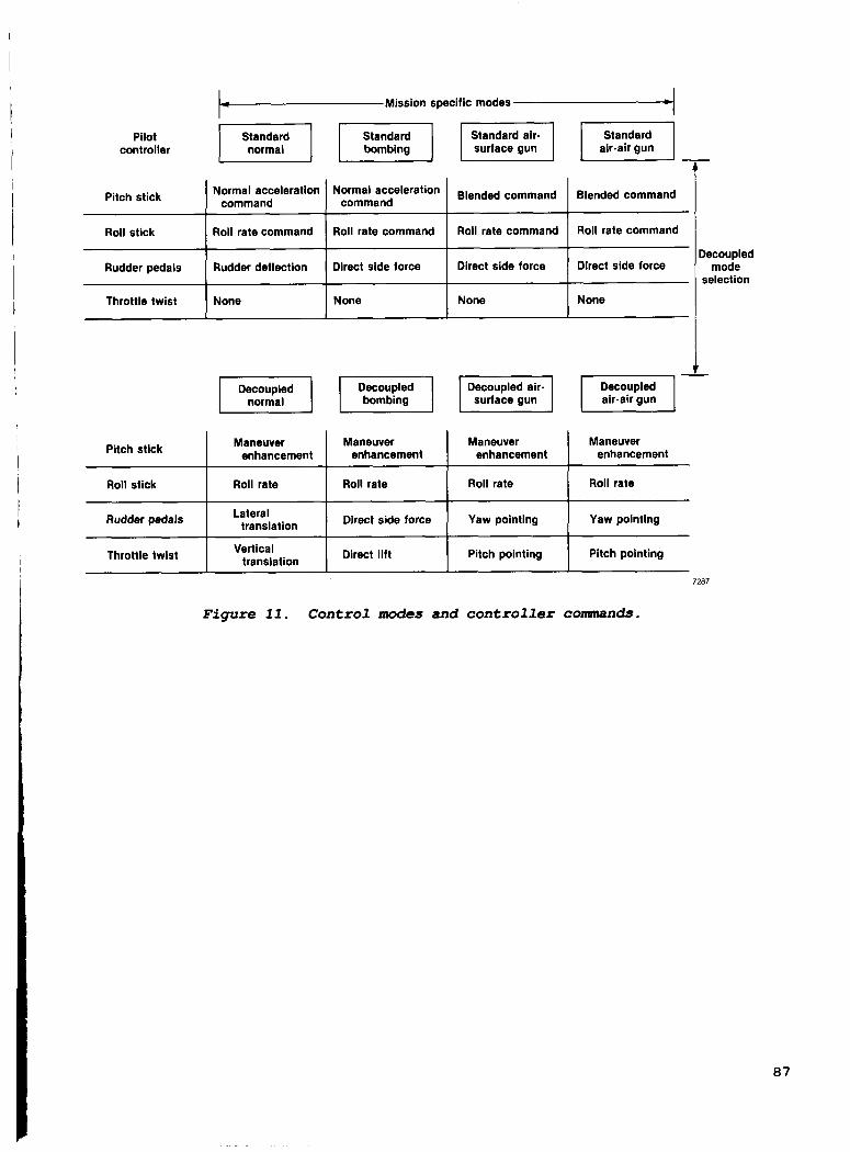
Mission specific modes
Pilot controller
7-
Rudder pedals
Throttle twist
Normal acceleration Normal acceleration Blended command command command Pitch stick
Rudder deflection Direct side force Direct side force
None None None
Roll stick
Maneuver Maneuver Maneuver enhancement enhancement enhancement Pitch stick
Roll stick Roll rate Roll rate Roll rate
Rudder pedals
Throttle twist
Direct side force Yaw pointing Lateral
Vertical Direct lift Pitch pointing
translation
translation
I Roll rate command 1 Roll rate command I Roll rate command
Maneuver enhancement
Roll rate
Yaw pointing
Pitch pointing
Blended command
Roll rate command
Direct side force
None
Decoupled mode
selection
7287
Figure 11 . Control modes and c o n t r o l l e r commands.
87

(a ) V e r t i c a l t r a n s l a t i o n : ver- t i c a l velocity control a t cons tan t p i t c h a t t i t u d e .
V y\ ,
(b) D i r e c t l i f t : v e r t i c a l f l i g h t p a t h control a t cons tan t angle of a t t a c k .
( d ) La te ra l t r a n s l a t i o n : l a t e r a l velocity c o n t r o l a t cons tant yaw a t t i t u d e .
(e) D i r e c t s i d e f o r c e : direc- t ional f l i g h t p a t h control a t zero s i d e s l i p ang le .
7288
(c) P i t c h p o i n t i n g : p i t c h a t t i - t u d e control a t cons tan t f l i g h t - p a t h angle .
(f) Yaw p o i n t i n g : d i r e c t i o n a l a t t i t u d e control a t cons tan t f 1 i g h t p a t h ang le .
Figure 12. Decoupled control d e s c r i p t i o n s .
88

HUD panel DFCS and avionics mode selection All mission-specific standard control
modes
Right MPD Independent DFCS mode selection All mission.specific standard control
modes Stores
Left MPD Independent DFCS mode selection All mission-specific standard control
modes - I management I
Right-hand controller Avionics 1 Decoupled mode multiplex selection
IBU selection (discrete inputs)
Throttle Dogfight switch DFCS and avionics
mode selection Air to air only
Figure 13.
Action selects test page
f FAULT DATA TEST PRSET AUTH
NORM NONE GCMD RUD
FLAP OPTIMUM
AUTO DRAG STORES MODUL
FCS
Digital flight control system
Fl igh t control mode s e l e c t i o n .
F FAULT OATA PRSET AUTH
t MEMORY C 0 N T E N T LOC
xxxx xxxx xxxx xxxx
BIT
FCS
7289
FCS base page
PRSET preset RUD rudder AUTH authority MODUL modulation NORM normal LOC location GCMD G. command FCS flight control system
(normal acceleration)
Figure 1 4 . tes t pages .
Multipurpose d i s p l a y s o f d i g i t a l f l i g h t control system base and
89

II FCS VID I II
PRSET preset AUTH authority ACK acknowledge VID video INU inertial navigation unit GBIAS G (normal acceleration) bias 7291
Figure 15. Multipurpose fault display.
90

Inter- computer data links
7292
Figure 16. Actuator in ter face t o d i g i t a l f l i g h t control system.
91

I- r I-
E tE -
r
L 3
1 -f
d
1
r I I I I
92
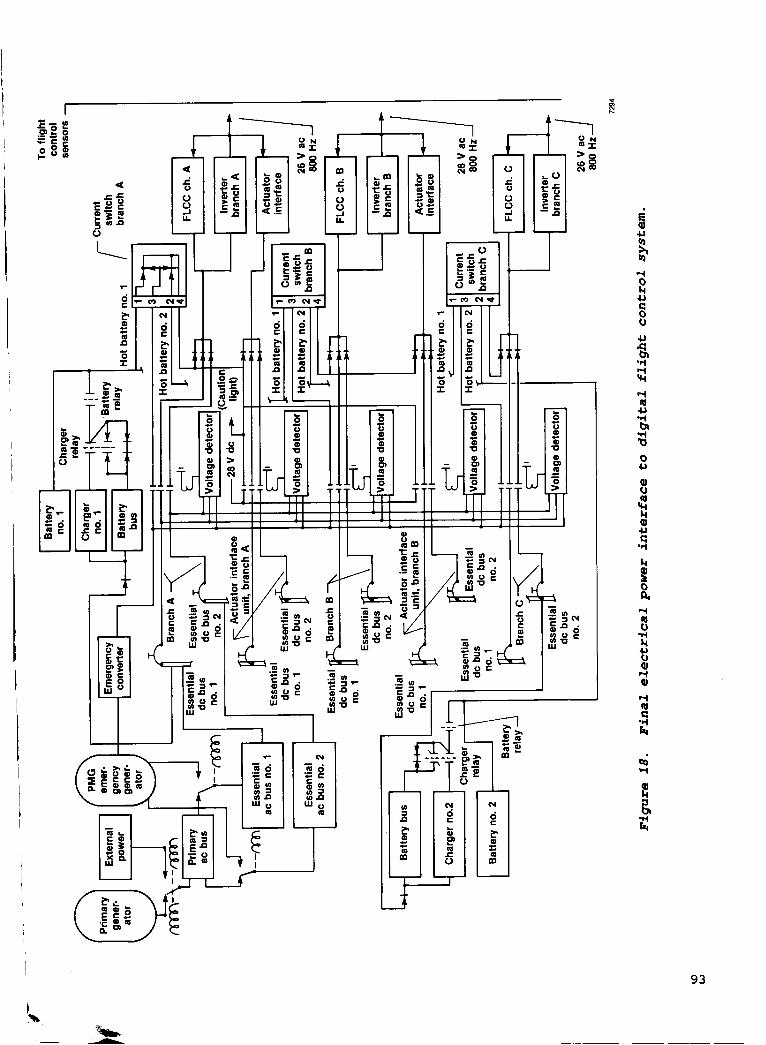
I
t
E
u
'1 1 ur 1 4 u 'e b '1 v 0 U
%I
93

94
- - Serial receiver
Channel C Scratchpad sensors memory
Serial receiver
11-1
" Serial receiver
Channel A Scratchpad sensors memory
Processor ii' Serial receiver I Channel B I I ,, I Scratchpad
sensors Serial receiver
FLCC B
f 1 -
I I 1
Processor 174
Figure 19. Cross-channel monitoring uses information sent on digital links.
C - 3-

t Input-output H controller
Central processing unit (CPU)
and memory i
Figure 2 0 . O v e r v i e w o f good-channel- average s e l e c t i o n .
Input A
Input B
Input C
Selected value
(good channel average)
Analog multiplexer
Sensor
/f-i-- Failure threshold ; A + +
4 f- LAverage Of
3
remaining good - A + B channels - - persistance I
frames I time =1/; 2
I
I I declared
failed w
Fail Fail Fault detection method
L 1. Three or more digital surface commands fail
1. Watchdog timer
Fault detection method
2. Consensus of other two channels
3. Self-test failure (only used to resolve failure when two channels remain)
--c
- Sensor
2 w
7297
1 - Analog- CPU Digital-
digital built-in-test analog t o operating to-
converter software converter 2 - r
Figure 21 . a channel f a i l u r e .
Logic used t o determine
. . . . I BIT bias injection signals rlq Sensor 1
7298
Figure 22. input c i r c u i t r y f a u l t s .
Bias i n j e c t i o n t o resolve sensor and
95

Decoupled normal SP-FPME SR-roll rate
T-translation
- CCV.control configured
- Controllers - SP-pitch stick - SR-roll stick - P-pedals - T-throttle twist
vehicle - FPME-flightpath
maneuver enhancement
- PRME-pitch rate maneuver enhancement
Reconfiguration Normal
acceleration Pitch rate Angle of attack Roll rate Yaw rate
Landing
t Standard normal SP-normal
SR-roll rate P-rudder
deflect T-none
acceleration
Decoupled air- to-air gun
SR-roll rate P-pointing T-pointing
SP-FPMEIPRME
t t .c Standard air- to-air gun SP-pitch rate SR-roll rate P-flat turn T-none
Decoupled air- to-surface gun SP-PRME SR-roll rate P-pointing T-pointing
t Standard air- to-surface gun SP-pitch rate SR-roll rate P-flat turn T-none -
I I Independent backup unit (from any digital mode) I
Decoupled air- to-surface bomb SP-FPME SR-roll rate P-flat turn T-direct lift
lever
Standard air.
SP-normal
SR-roll rate P-flat turn T-none
to- surf ace bomb
acceleration
50
40
30 Altitude, 1000 ft ~
Figure 23. Standard and decoupled mission specific control s t r u c t u r e .
20
10
0
0 SNRM gains E B l Transition region from bombs
n SASB mode optimal gains mode gains to normal mode gains
-
.2 .4 .6 .8 1.0 1.2 1.4 7300
Mach number
Figure 2 4 . Bombing mode f l i g h t envelope and gain changes.
7299
N1 Mach number 10.00 ' I I
1 10.2) I 5) I I
6.90 7.50
4.60 5.83 4.60 4.01 4.14
3.45 2.00 3.10 1.67 1.10
n " 50,000 30,000 10,000 Sea
level Altitude, ft 7301
Figure 25. Longitudinal f e e d forward gain N1 requ i r ing double i n t e r p o l a t i o n .
96
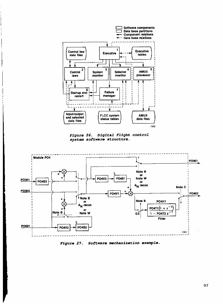
0 Software components 0 Data base partitions - Component relations *-- Data base relations
----------------- - - I I
I I
1 Executive data files
3 4 ' 5 1 System Selector ! AMUX I [ monitor monitor processor 1 Control
laws I I A A A 4' 1 ! . ) .
Startup and - 1 ; ; ;
I I I I I I I I
I I I
I I I I I
I - ; ; 7 1 1 1 l l
I -_I I 1 I I I 1
' Failure
I I restart 7 manager I I I I I
6 1
I I I I I _ I ; I j 1 ; , - - - - - - - - - - - - - - I ----- J I I_- J L A r L;
I ------ ---- 4 - L - - L - l I
I
7302
Figure 26. Digital flight control system software structure.
I Module PO4 I I I I I I
I PO303 I
I I I I I I I I I I I I
PO601 ! I I I
I ! I I
; PO401 I ., I I I
-1, I I L
: I + I P04V1
or 6-1 A, recon
Note B or
Note W or
A,,, recon Note C
I Filter
7303
I I I I I I I I I I
; PO402 I I I I I I I
c
I
97
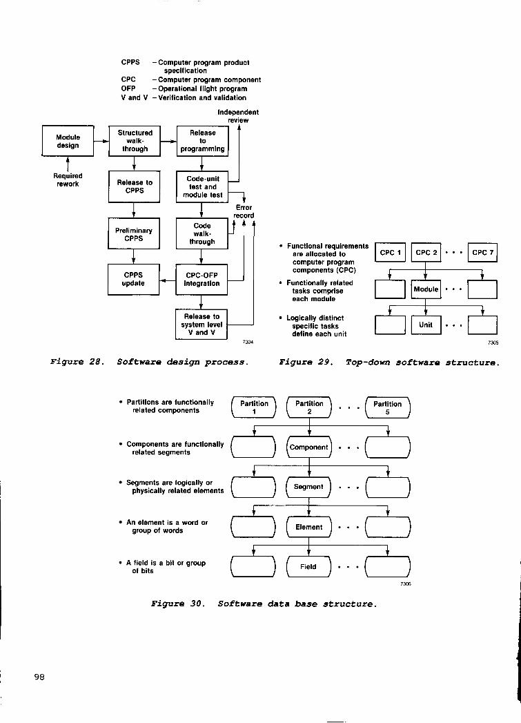
CPPS -Computer program product specification
CPC -Computer program component OFP -Operational flight program V and V -Verification and validation
Independent review
I , I r A I Module H stz:i~d H I 1 design through programming
Code-unit
module test
Release to
Preliminary through
CPC-OFP update integration
4 A
1 lcpcll pq Functional requirements are allocated to computer program components (CPC)
Functionally related tasks comprise each module
Release to Logically distinct
define each unit system level specific tasks
V and V 7304 7305
Figure 2 8 . Software des ign p r o c e s s . Figure 29 . Top-down so f tware s t r u c t u r e .
Partitions are functionally related components
Components are functionally ( ) ( c o m p y n t ) . ( related segments
1 A 1
Segments physically are related logically elements or (-) (Segment) . . . [ )
An group element of words is a word or (-) ("T""') ' (-) A of field bits is a bit or group (-) (ZT) (-)
Figure 30 . Software da ta base s t r u c t u r e .
I 98

System specification
Preliminary design
documentation (mechanization
document)
Software design
Unit program product
specification gramming software team package
Retest r . Software
test to the Mechanization
(updated)
Discrepancy causes remechanization specification validation:
(updated) FMET and
FMET failure modes and effects testing FQ flying qualities testing
Flight qualified system
First flight
Integrated system test (validation) complete
Stand-alone test complete
First DFCS software release
Test environment
Emulation of flight computer on software development station
Triplex flight computer complex
Complete flight control hardware with aerodynamic simulation
7307
Figure 31. System-software qualification and design iterations.
AScheduled Actual A
A Scheduled Actual A
A Scheduled A Actual
A A Actual Scheduled
J I 1 I I I I I I I I I I I I I I I I 1 1 1 1 ) O N D J F M A M J J A S O N D J F M A M J J A
I I
Complete, percent
100
80
60
40
20
1981 1982
7308 Time, mo
Figure 32. Qualification schedule.
0
- - -
1 2 3 4 5 6 7 a 9 1 0 Months from test initiation 7309
Figure 33. and testing .
History of software coding
99

100
80
60-
40-
20-
Complete, percent
I 100
- Originally
-/ EzRePqEn date
Figure 3 4 . History o f Software v e r i f i c a t i o n .
100
8 0 -
60-
40-
20-
bus simulation
Transmit and receive single
message Switch from
7 scheduled - completion
Actual completion
I I l l I l l *
Complete, percent
Computer control unit (CCU) AIU - - - OFP loading FLCC A
OFP patching FLCC monitoring - FLCC control
- FLCC B
FLCC C
ETSE input-output test panel
Redundant input
- -
I I Strip-chart .t
I recorder I -
I Strip-chart I -
+ I
+ I I I
I
recorder
FLCC interface
insertion panel
Redundant input
Recording I malfunction fault
I. Multiplex interface I
I t
Figure 35. H i s t o r y o f system v a l i d a t i o n .
ahd output simulation interface
Test voltages - Bias test voltages Failure mode +. - Failure mode Simulation
and output FLCC simulation
simulation I I I
- - Multiplex analyzer
Figure 36 . Support equipment f o r v e r i f i c a t i o n t e s t i n g .
t t t Single word I generator
I I I I RM test I
FLCC A to FLCC B
4 - I signal d i s p I a y I
I Manual control
7312
-- Bus control Bus monitor
Avionics I I I
multiplex bus

L
Scan converter (525 line)
- 1 picture system
- SMS and PDG emula tor
Visual system
Light projector Target projection system Earth-sky-horizon projector Visual interface
FCC support
Programmable Stores Fire control management computer - display
generator (PDG)
7313
set (SMS) (FCC)
Figure 37. Validation support equipment.
t 4 4 4 - 9 4 1 AMUX * interface
Strip-chart recorders
101
- Cockpit ETSE- FLCC FLCC interface Patch panel Computer system - interface - Dual mainframe MPDs, HUD interface monitor - fault insertion
computer with Stick panel panel peripherals Pedals
Relative geometry Simulated analog ISAs INU, radar
Air-to-air target Left horizontal tail Air-tomground target Right horizontal tail Real-time scoring Left trailing-edge flap Data acquisition Right trailing-edge flap Data display Left canard Initialization
Throttle twist Linear throttle ADI, HSI Rpm indicator Altimeter Mach-airspeed Angle-of -attack
indicator Right canard Visual system drives
Angle-of-attack indexer
FLCC - interface malfunction and cockpit
t w 4
FLCC A m - Rudder
t Video
Interface software

altitude, 30 Pressure
1000 ft 40i 0 0
2ol: 10
500
(1.2150,OOO)
(1.6130,OOO)
-
(1.411 0,000) 1
1.6150,OOO)
Mach number 7314
Figure 3 8 . Phase 1 stress test cond i t ions .
Point A Mach 1.2 at 500 ft, maximum g, 90' pitch up Point B Perform desired maneuver from table Point C Pitch over to -90" pitch attitude Point D Perform desired maneuver from table Point E 11,000 ft begin maximum g pullout Point F Mach 1.215000 ft, reset Note: Throttle set at maximum afterburner power
throughout test trajectory for phase 2
50,000
40,000
Pressure 30,000 altitude,
ft 20,000
10,000
B
7315 Downrange
Figure 39. Stress t es t , i n s i d e loop.
102

103

Aircraft sensors laws
30-
deg 0
T I
FLCC C
Lateral accelerations
1.2 r -1.2 u r
-1.2 I
l.* r -1.2 u
Airframe I Figure 4 1 . Setup for structural coup1 i n g t es t s .
7311
Rudder commands before fix
30
deg 0
- 30
30
- 30
30
- 30
Rudder commands after fix
deg 0 A
- 30
30
FLCC deg 0 B
-30 w
- 30 u I Time 7318
b
Figure 4 2 . Gunfire test data.
104

30
20 Flights
Per mo.
10
0
update -c Analysis
design
New hardware system
requirement
+ and
Design change required -,
Hardware Inspection
modlflcatlon or fabrication * asgs",$&
Discrepancy noted +
- TXX 0 Software release no.
Discrepancy report - analysis
7319
Figure 4 3 . Configuration control p r o c e s s .
New Analysis Documen- Assemble
test c and tatlon - new 4 software system design update release
requirement - *
T12
i?i
Vehicle preflight
test
- T3 -
T7 T4
0 7 4 9 0 20 14 27-
Validation test
Software change notice
-
I J A S O N D J F M A M J J 1982 1903
Flight test
F i g u r e 4 4 . F l i g h t test sunmary.
I
Delay
- 21.5 I 0.0 -t B 1 I 1 - 1
1
Limiter
i Proportional + integral
steady-state decoupling
From 1
I I I I I 1 I I I I I I I I
I To I control I surfaces
G-- I 1 I 1
.J
dback 7320 sensors 7321
F i g u r e 4 5 . s w i t c h used i n the control l a w s .
Example o f a s o f t w a r e
105
Power sources - Engine
bleed air
28 v Regulated 28 V
generator output *
Emergency Unregulated permanent magnet generator ac voltage
power unit
emergency
-20 -15 -10 -5
Sideslip, 0
10 15 20 25
deg
- - - - -
5 -
- -
-
Hydrazine 1 and 1 \ [YE - converter turbine generator
Overvoltage detected 1 _ _ _
- ' /*------
Normal operation 80-percent throttle
7322 Time
Figure 46. Overview of electrical system over- voltage shutdown.
Normal f , acceleration,
9 -2 1 sec -4 -6
Figure 47. N o r m a l acceleration and sideslip of flight 36 yaw departure.
Scales are not relative
Air data sensor A, nose boom Air data sensor B. nose boom
Selected air data
Random in time due to
asynchronous
Computer A, gain update Computer B, gain update Computer C, gain update I j operation
ComDuter A. surface command Computer B, surface command- Cornouter C. surface command I I
- to + 0.25 sec to + 1.0 sec
7324 Time
Figure 48. How an air data failure causes errors in surface commands.
106

Digital 20 - Channel A commands
for right flaps, deg -20
value of dynamic 400 pressure, 350 -
Channel C Digital 20 r-
1 sec
I
n
commands for right
flaps, deg -20 * Selected 640 r- Average of 3 7 rAve rage Of
Figure 49. effects on surface commands.
A i r data trans ients and
Flights 1-9
Not flown
Flights 10.15
Flights 16-25
Flights 26-35
Flights 36-39
Flights 40-48
Flights 49-56
Flights 57-77
Flights 78-86
Flights 87-96
Flights 97.101
Flights 102.118
1982
ware relec I '02
s-
A TO3
c I
1983
Rpr Ma)
'08 rn n To9 I-
I I
- uric -
'10
a- m
13
7326
Figure 50. Software re l ease sumnary.
107
D64 Rudder structural breakout limits
I I
x 2.5 - Rudder pedal - 20 input = 20 Ib S I
I
Rudder command,
deg
- command 10 - S fault -
25.0
D64
14.0 12.5
9.0 7.0 5.0
2.5
0
jl). Channel B
1
qc, lb/ft2 7327
I
2.6i I 2 0 O I
Figure 5 1 . ment v e r t i c a l t a i l load l i m i t i n g .
Rudder l i m i t used t o imple-
ClO! c
I I D69 I
20 S
Rudder pedal - input = 20 Ib
Airspeed inputs Channel = knots
A 175 B 172 C 170 2.6
Canard command,
deg 1.0
0
I Channel A I
Channel C Pool I . 8 O
D69 output values I I for corresponding
I airspeed inputs
tional'bl&ks
Channel A
32 O
Channel B I
Channel C
Outputs after integrator
I I I I I I I I
- 1 I I Normalized
I to canard
I
I outputs
52'1 surface
I I
- 1
Channel A
Channel B
Channel C
I 0 1 2 3 4 Frames (time) I
I I Output values sent to
fault detectlon routines 7328
Figure 52. Summary o f cond i t ions causing f l i g h t 44 anomaly.
108

ORIGINAL PAGE IS OF POOR QUALtTY
A -
I I I I I I
I I I I I I I I I I I I I I I I I I I I I I I I I I I I I I
I I I r--
I
I
I
I Z
I I I I I I I I I I I - I I I I I I
I
; f€ l f I
L----- I:
-- - I i------- I
++-I-,
I I I I I I I I I I I I I I I I I I I I I I I I I I I I
I I
* I I I I I I I I I I I I
I ;
. - - - - - - - I
109
r I E; I
-
h
z-- I 1
110

Y07K3 I I I I I
I I I
Y07K1 Y07V1
I Absolute Positive I
value I value I
I I I
I I I I I I I I I I I I I I I I I I
Figure 55. Angle-of-attack gain t o aileron-rudder interconnect .
PO701
l- Limiter I Fixed gain
Y07V1 Variable '171 Y07K3
gain
Positive value 7332
Absolute I value Y07K1
Figure 56. i n t o indiv idual blocks.
Control law module broken
111

Report Documentation Page 1. Report No.
NASA TP-2857 2. Government Accession No. 3. Recipient's Catalog No.
19. Security Classif. (of this report)
u n c l a s s i f i e d
5. Report Oate
November 1988
20. Security Classif. (of this page) 21. No. of pages
116
22. Price
A0 6 u n c l a s s i f i e d
6. Performing Organization Code
8. Performing Organization Report No. H-1344
10. Work Unit No.
RTOP-999-12-08
11. Contract or Grant No.
13. Type of Report and Period Covered
Technica l Paper
14. Sponsoring Agency Code
16. Abstract
I Engineers and s c i e n t i s t s i n t h e advanced f i g h t e r technology i n t e g r a - t i o n (AFTI) F-16 program i n v e s t i g a t e d t h e i n t e g r a t i o n of emerging tech- n o l o g i e s i n t o an advanced f i g h t e r a i r c r a f t . A F T I ' s t h r e e major technol - o g i e s inc luded ( 1 ) f l i g h t - c r u c i a l d i g i t a l c o n t r o l , ( 2 ) decoupled a i rc raf t f l i g h t c o n t r o l , and ( 3 ) i n t e g r a t i o n of a v i o n i c s , f l i g h t c o n t r o l , and p i l o t d i s p l a y s . In a d d i t i o n to i n v e s t i g a t i n g improvements i n f i g h t e r perform- ance , r e s e a r c h e r s s t u d i e d t h e g e n e r i c problems conf ron t ing t h e d e s i g n e r s of h i g h l y i n t e g r a t e d f l i g h t - c r u c i a l d i g i t a l c o n t r o l . The a u t h o r p rov ides a n overview of both t h e advantages and problems of i n t e g r a t i o n d i g i t a l c o n t r o l systems. An examination of t h e s p e c i f i c a t i o n , des ign , q u a l i f i c a - t i o n , and f l i g h t test l i f e - c y c l e phase is provided. An overview i s g iven of t h e f a u l t - t o l e r a n t des ign , multimcded decoupled f l i g h t c o n t r o l l a w s , and i n t e g r a t e d a v i o n i c s des ign . The approach t o q u a l i f y i n g t h e so f tware and system des igns i s d i scussed , and t h e e f f e c t s of des ign c h o i c e s on system q u a l i f i c a t i o n a r e h i g h l i g h t e d .
17. Key Words (Suggested by Author(s1) F l i g h t c o n t r o l F l i g h t test v a l i d a t i o n ve r i f i c a t i on
18. Distribution Statement I Unclas s i f i ed - Unlimited
S u b j e c t c a t e g o r y 08
NASA FORM 1628 OCT 88 *For sale by the National Technical Information Service, Springfield, Virginia 22161
NASA-Langley, 198