Embed Size (px)
Citation preview

1
Design and proof of concept of a continuous pressurized multistage fluidized bed unit for deep removal of sour gas using adsorptionRick T. Driessen, Benno Knaken, Tim Buzink, Daan A.F. Jacobs, Juraj Hrstka,
Derk W.F. Brilman
Sustainable Process Technology, University of Twente, Enschede (The Netherlands)[email protected]
29 May 2019

2
v
Agenda
Introduction Results andproof of concept
ConclusionsPilot plant design
Background and goals

3
v
Disadvantages of fixed bed adsorption
Ineffective use of sorbent Slow heat transfer
0
1
0 1
C/C i
n
z/L
fixed bed adsorber
T
Only this part of thebed is active

4
v
Continuous adsorption process
Product gas
Gas + impurities
Impurities + purge gas
Purge gas
Adsorber(low T)
Desorber(high T)
solid
sor
bent
Driessen et al., Ind. Eng. Chem. Res., 57, 3866-3875 (2018)

5
v
Continuous adsorption process
Product gas
Gas + impurities
Impurities + purge gas
Purge gas
Adsorber(low T)
Desorber(high T)
solid
sor
bent
Driessen et al., Ind. Eng. Chem. Res., 57, 3866-3875 (2018)
Heat transfer
Effective use of sorbent

6
v
Continuous pressure swing
AdsorberElevated pressure
HP/LP lock
DesorberLow pressure
LP/HP lock
Feed gas + Adsorbates
Adsorbates + Purge gas
Sorbent circulation
Purge gas
Product gas

7
v
Continuous pressure swing
CaseCO2 and H2S removal from natural gas using supported amine sorbents
GoalShow that continuous PSA in a MSFB is technically possible for sour gas removal from natural gas.
AdsorberElevated pressure
HP/LP lock
DesorberLow pressure
LP/HP lock
Feed gas + Adsorbates
Adsorbates + Purge gas
Sorbent circulation
Purge gas
Product gas
7.0 m

8
v
Rotary valve
Back pressureregulator
Riser
N2
Buffer
LP/HP lock
Buffer
Adsorber
to HP/LP lock
Cyclone
N2/CO2
to analyser
Design of pilot plant1 bara
10 bara
10 bara
1 bara
1/10 bara
30 - 60 °C
Top section

9
v
Rotary valve
Back pressureregulator
Riser
N2
Buffer
LP/HP lock
Buffer
Adsorber
to HP/LP lock
Cyclone
N2/CO2
to analyser
Design of pilot plant1 bara
10 bara
10 bara
1 bara
1/10 bara
30 - 60 °C
PI-1
V-2
V-1A
V-1B
V-3
V-4A
V-4B
PCVN2
LP/HP lock
Top section

10
v
Rotary valve
Back pressureregulator
Riser
N2
Buffer
LP/HP lock
Buffer
Adsorber
to HP/LP lock
Cyclone
N2/CO2
to analyser
Design of pilot plant1 bara
10 bara
10 bara
1 bara
1/10 bara
30 - 60 °C
Top section

11
v
Rotary valve
Back pressureregulator
Riser
N2
Buffer
LP/HP lock
Buffer
Adsorber
to HP/LP lock
Cyclone
N2/CO2
to analyser
Design of pilot plant1 bara
10 bara
10 bara
1 bara
1/10 bara
30 - 60 °C
3 stage MSFB(50 mm ID)
Top section

12
v
Rotary valve
Rotary valve
Riser
From adsorber
HP/LP lock
Buffer
Desorber
N2
Design of pilot plant
1 bara
10/1 bara
1 bara
100 °C
Bottom section

13
v
Rotary valve
Rotary valve
Riser
From adsorber
HP/LP lock
Buffer
Desorber
N2
Design of pilot plant
1 bara
10/1 bara
1 bara
100 °C
Bottom section
7 stage MSFB(200 mm ID)

14
v
Results
Bos et al., Chem. Eng. J., doi:10.1016/j.cej.2018.11.072 (2018)
Murphree tray efficiency‘Extent to equilibrium’
Definition of tray efficiency

15
v
1 2 3
Stage
0.0
0.2
0.4
0.6
0.8
1.0
Etr
ayG
[-]
S = 1.02 kg/(mR2 s)
S = 1.53 kg/(mR2 s)
S = 2.04 kg/(mR2 s)
S = 3.06 kg/(mR2 s)
Inlet 1 2 3
Stage
10 0
10 2
10 4
Con
cent
ratio
n C
O2
[mol
ppm
]
S = 1.02 kg/(mR2 s)
S = 1.53 kg/(mR2 s)
S = 2.04 kg/(mR2 s)
S = 3.06 kg/(mR2 s)
3.5 mol ppm specification
1 2 3
Stage
20
30
40
50
60
70
Tem
pera
ture
[° C
]
S = 1.02 kg/(mR2 s)
S = 1.53 kg/(mR2 s)
S = 2.04 kg/(mR2 s)
S = 3.06 kg/(mR2 s)
ResultsVarying solid flux
Parameters• P = 10 bara• cin = 20 000 mol ppm• u0 = 0.084 m/s• H = 130 mm

16
v
1 2 3
Stage
0.0
0.2
0.4
0.6
0.8
1.0
Etr
ayG
[-]
S = 1.02 kg/(mR2 s)
S = 1.53 kg/(mR2 s)
S = 2.04 kg/(mR2 s)
S = 3.06 kg/(mR2 s)
Inlet 1 2 3
Stage
10 0
10 2
10 4
Con
cent
ratio
n C
O2
[mol
ppm
]
S = 1.02 kg/(mR2 s)
S = 1.53 kg/(mR2 s)
S = 2.04 kg/(mR2 s)
S = 3.06 kg/(mR2 s)
3.5 mol ppm specification
1 2 3
Stage
20
30
40
50
60
70
Tem
pera
ture
[° C
]
S = 1.02 kg/(mR2 s)
S = 1.53 kg/(mR2 s)
S = 2.04 kg/(mR2 s)
S = 3.06 kg/(mR2 s)
ResultsVarying solid flux
Parameters• P = 10 bara• cin = 20 000 mol ppm• u0 = 0.084 m/s• H = 130 mm
From 20 000 ppm to <10 ppmin 0.5 s
Concentrations lower by orders of magnitude
17
v
1 2 3
Stage
0.0
0.2
0.4
0.6
0.8
1.0
Etr
ayG
[-]
S = 1.02 kg/(mR2 s)
S = 1.53 kg/(mR2 s)
S = 2.04 kg/(mR2 s)
S = 3.06 kg/(mR2 s)
Inlet 1 2 3
Stage
10 0
10 2
10 4
Con
cent
ratio
n C
O2
[mol
ppm
]
S = 1.02 kg/(mR2 s)
S = 1.53 kg/(mR2 s)
S = 2.04 kg/(mR2 s)
S = 3.06 kg/(mR2 s)
3.5 mol ppm specification
1 2 3
Stage
20
30
40
50
60
70
Tem
pera
ture
[° C
]
S = 1.02 kg/(mR2 s)
S = 1.53 kg/(mR2 s)
S = 2.04 kg/(mR2 s)
S = 3.06 kg/(mR2 s)
ResultsVarying solid flux
Parameters• P = 10 bara• cin = 20 000 mol ppm• u0 = 0.084 m/s• H = 130 mm
From 20 000 ppm to <10 ppmin 0.5 s
Equilibrium is almost reached
Temperature increase dueto increased sorbent flow
from desorber
Concentrations lower by orders of magnitude

18
v
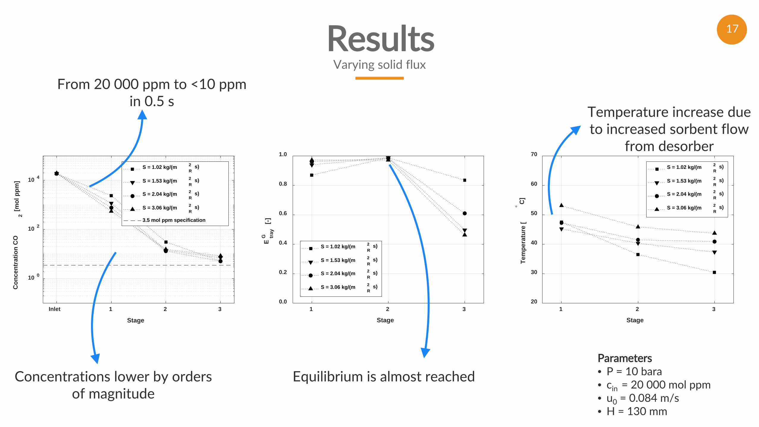
ResultsEffect of diverter on top stage

19
v
ResultsEffect of diverter on top stage
Diverter
20
v
ResultsEffect of diverter on top stage
Diverter
Inlet 1 2 3
Stage
10 -1
10 0
10 1
10 2
10 3
10 4
10 5
Con
cent
ratio
n C
O2
[mol
ppm
]
without diverterwith diverter
3.5 mol ppm specification
1 2 3
Stage
20
30
40
50
60
70
Tem
pera
ture
[° C
]
without diverterwith diverter
1 2 3
Stage
0.0
0.2
0.4
0.6
0.8
1.0
Etr
ayG
[-]
without diverterwith diverter
Parameters• P = 10 bara• cin = 20 000 mol ppm• u0 = 0.084 m/s• H = 130 mm
Sorbent bypassing without diverter is significant

21
v
Inlet 1 2 3
Stage
10 0
10 2
10 4
Con
cent
ratio
n C
O2
[mol
ppm
]
cin
= 37.300 mol ppm
cin
= 24.100 mol ppm
cin
= 10.600 mol ppm
cin
= 4.800 mol ppm
3.5 mol ppm specification
1 2 3
Stage
20
30
40
50
60
70
Tem
pera
ture
[° C
]
cin
= 37.300 mol ppm
cin
= 24.100 mol ppm
cin
= 10.600 mol ppm
cin
= 4.800 mol ppm
1 2 3
Stage
0.0
0.2
0.4
0.6
0.8
1.0
Etr
ayG
[-]
cin
= 37.300 mol ppm
cin
= 24.100 mol ppm
cin
= 10.600 mol ppm
cin
= 4.800 mol ppm
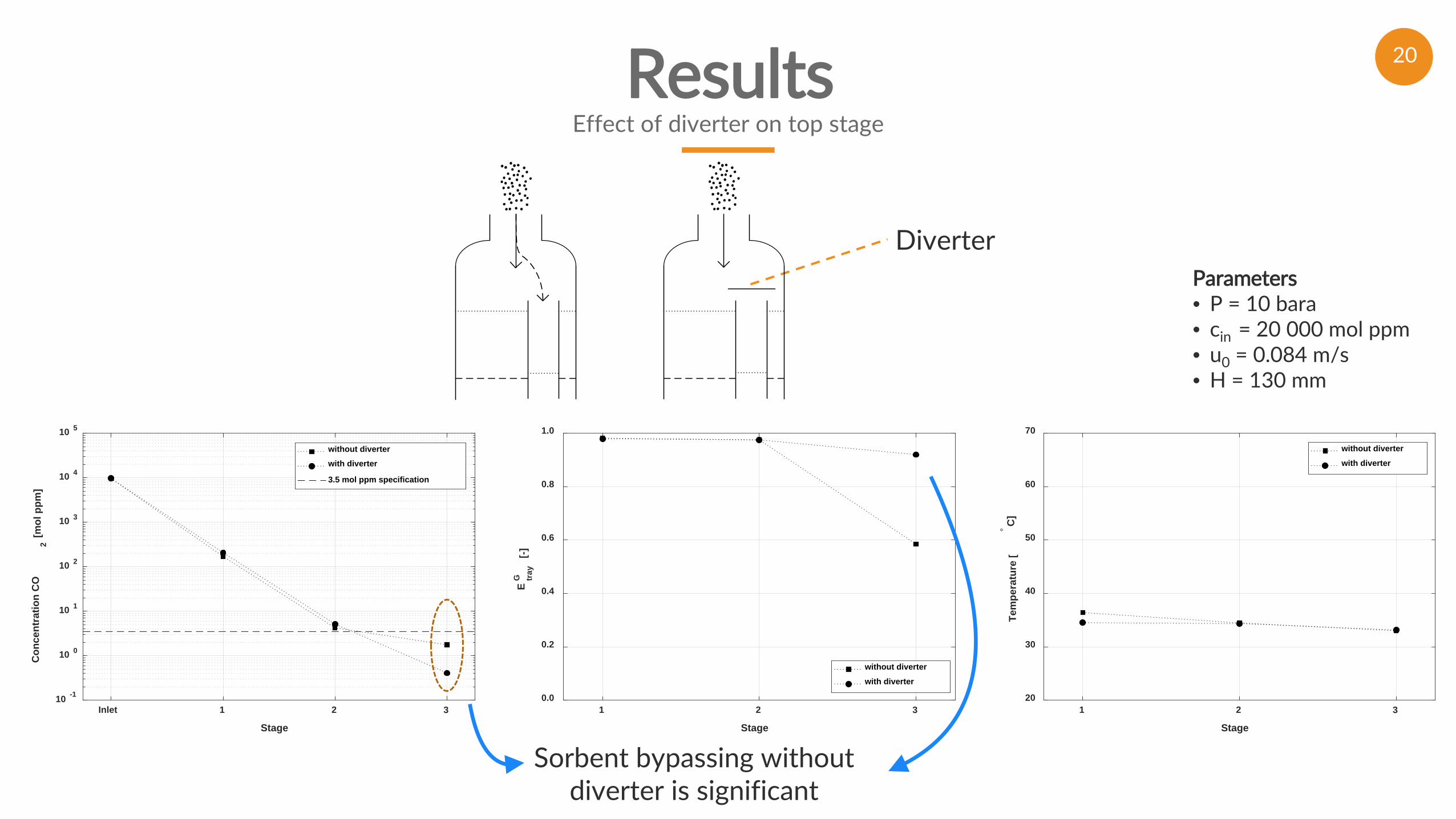
ResultsVarying inlet concentration
Parameters• P = 10 bara• u0 = 0.084 m/s• S = 2.04 kg/(mR
2 s)• H = 130 mm
22
v
Inlet 1 2 3
Stage
10 0
10 2
10 4
Con
cent
ratio
n C
O2
[mol
ppm
]
cin
= 37.300 mol ppm
cin
= 24.100 mol ppm
cin
= 10.600 mol ppm
cin
= 4.800 mol ppm
3.5 mol ppm specification
1 2 3
Stage
20
30
40
50
60
70
Tem
pera
ture
[° C
]
cin
= 37.300 mol ppm
cin
= 24.100 mol ppm
cin
= 10.600 mol ppm
cin
= 4.800 mol ppm
1 2 3
Stage
0.0
0.2
0.4
0.6
0.8
1.0
Etr
ayG
[-]
cin
= 37.300 mol ppm
cin
= 24.100 mol ppm
cin
= 10.600 mol ppm
cin
= 4.800 mol ppm
ResultsVarying inlet concentration
Parameters• P = 10 bara• u0 = 0.084 m/s• S = 2.04 kg/(mR
2 s)• H = 130 mm
Pressurized MSFB technologyis also suitable for high
concentrations
H2S specification (<3.5 ppm) can be reached

23
v
Inlet 1 2 3
Stage
10 0
10 2
10 4
Con
cent
ratio
n C
O2
[mol
ppm
]
cin
= 37.300 mol ppm
cin
= 24.100 mol ppm
cin
= 10.600 mol ppm
cin
= 4.800 mol ppm
3.5 mol ppm specification
1 2 3
Stage
20
30
40
50
60
70
Tem
pera
ture
[° C
]
cin
= 37.300 mol ppm
cin
= 24.100 mol ppm
cin
= 10.600 mol ppm
cin
= 4.800 mol ppm
1 2 3
Stage
0.0
0.2
0.4
0.6
0.8
1.0
Etr
ayG
[-]
cin
= 37.300 mol ppm
cin
= 24.100 mol ppm
cin
= 10.600 mol ppm
cin
= 4.800 mol ppm
ResultsVarying inlet concentration
Parameters• P = 10 bara• u0 = 0.084 m/s• S = 2.04 kg/(mR
2 s)• H = 130 mm
Tray efficiencies remain high: >90%
Pressurized MSFB technologyis also suitable for high
concentrations
H2S specification (<3.5 ppm) can be reached
Temperature increase dueto exothermic adsorption

24
CompactA pressurized MSFB provides small adsorption equipment.
Conclusions
PossibleContinuous PSA is technically possible and demonstrated.
FastDeep removal is possible: 40 000 ppm to <10 ppm in <2 s.
EfficientEquilibrium is almost reached at every stage.