Embed Size (px)
Citation preview

U.S. Department o f A g r i c u l t u r e Soi 1 Conserva t ion S e r v i c e Eng ineer ing D i v i s i o n
SOIL MECHANICS NOTE NO. 7
THE MECHANICS OF SEEPAGE ANALYSES
October 1979
•
•
•
u.s. Department of AgricultureSoil Conservation ServiceEngineering Division
SOIL MECHANICS NOTE NO. 7
THE MECHANICS OF SEEPAGE ANALYSES
October 1979

•
•
•
•

Table o f Contents
. . . . . . . . . . . . . . . . . I . P u r p o s e a n d s c o p e
. . . . . . . . . . . . . . . . . . . I 1 . I n t r o d u c t i o n
. . . . . . . . . . . . . I 1 1 . Requi red S i t e I n f o r m a t i o n
I V . C o n s i d e r a t i o n s r e l a t i n g t o seepage ana lyses . . . .
. . . . . . . . . . . . . . . . V . Methods o f a n a l y s i s
A . Flow ne ts . . . . . . . . . . . . . . . . . . . . . . . . . . . . . . . . . . . . . B S p e c i a l cases
1 . P h r e a t i c l i n e f o r an embankment . . . . .
2 . Unconf ined a q u i f e r w i t h v e r t i c a l o r s t e e p l y s l o p i n g i n l e t and o u t l e t faces .
3 . Conf ined a q u i f e r w i t h f i n i t e l e n g t h . . .
. . . . . . . . 4 . B l a n k e t - A q u i f e r S i t u a t i o n s
Page No .
1
1
1
2
3
3
5
6
Appendix A . Examples
•Table of Contents
I. Purpose and Scope
I I. Introducti on
III. Required Site Information
IV. Considerations relating to seepage analyses
V. Methods of analysis
A. Flow nets . .
PageNo.
1
1
1
2
3
3
B. Special cases
•l.
2.
3.
4.
Phreatic line for an embankment
Unconfined aquifer with vertical orsteeply sloping inlet and outlet faces
Confined aquifer with finite length
Blanket-Aquifer Situations .
5
6
6
13
13
•
Appendix A - Examples

•
•
•

U.S. Department o f A g r i c u l t u r e S o i l C o n s e r v a t i o n S e r v i c e E n g i n e e r i n g D i v i s i o n
October 1979
S o i l Mechanics Note No. 7 : The Mechanics o f Seepage Analyses
I. Purpose and scope
Accepted methods f o r a n a l y s i s o f seepage and groundwater f l o w a r e p resen ted h e r e i n . Most o f t hese methods a r e g e n e r a l l y a p p l i c a b l e t o a v a r i e t y o f s t r u c t u r e s and f o u n d a t i o n s . A n a l y t i c a l and g r a p h i - c a l p rocedures a r e g i v e n w i t h examples t o demonst ra te t h e i r use.
11. I n t r o d u c t i o n
The p r i n c i p l e s of w a t e r f l o w t h r o u g h s o i l s a r e used t o d e t e r m i n e seepage q u a n t i t i e s , p ressu res , and f o r c e s . There a r e approx ima te s o l u t i o n s f o r s p e c i f i c boundary c o n d i t i o n s . These a r e g e n e r a l l y l i m i t e d t o t h e s o l u t i o n o f one va lue , u s u a l l y seepage q u a n t i t y . The process o f d e t e r m i n i n g boundary c o n d i t i o n s , s e l e c t i n g permea- b i l i t y va lues, and making t h e a n a l y s i s i s a l o g i c a l approach f o r e v a l u a t i n g s t r u c t u r e and f o u n d a t i o n per formance and f o r s e l e c t i n g a p p r o p r i a t e c o n t r o l measures. R e f e r t o S o i l Mechanics Note No. 6 f o r d e f i n i t i o n s .
111. Requ i red s i t e i n f o r m a t i o n
S i t e i n f o r m a t i o n s p e c i f i c a l l y r e l a t i n g t o p e r m e a b i l i t y o f m a t e r i a l s and seepage f l o w must be c o l l e c t e d f o r each s i t e . T h i s i n c l u d e s i n f o r m a t i o n f o r l o c a t i n g boundar ies between m a t e r i a l s o f d i f f e r e n t p e r m e a b i l i t y . G e n e r a l l y , t h e f o l l o w i n g i t e m s a r e r e q u i r e d t o e v a l u a t e s i t e c o n d i t i o n s f o r making seepage a n a l y s i s :
A . Topograph ic maps o f t h e s i t e a rea .
B . D e t a i l e d g e o l o g i c maps and s e c t i o n s o f t h e s i t e t h a t c o n t a i n c o r r e l a t i o n o f a1 1 s t r a t a o r zones between i n v e s t i g a t i o n p o i n t s . Maps shou ld i n c l u d e f e a t u r e s such as r e s e r v o i r s , channe ls , and o t h e r i t ems t h a t may a f f e c t downstream areas and a d j a c e n t v a l l e y s . Geo log ic i n f o r m a t i o n i s t o be i n t e r - p r e t e d t o i n d i c a t e u n i f o r m i t i e s , d i s c o n t i n u i t i e s , i s o t r o p y , a n i s o t r o p y , p o r o s o i ty, i n t e r v o i d permeabi 1 i ty, mass permea- b i l i t y , e t c .
C . D e t a i l e d l o g s and d e s c r i p t i o n s o f a l l m a t e r i a l s i n t h e embank- ment f o u n d a t i o n and r e s e r v o i r abutments. I tems such as grada- t i o n , s o i l s t r u c t u r e , s t r a t i f i c a t i o n , c o n t i n u i t y o f s t r a t a , bedrock p r o f i l e s , a r t e s i a n p r e s s u r e , and m o i s t u r e c o n t e n t a r e i m p o r t a n t .
T h i s Note p repared by James R . T a l b o t and Rober t E. Ne lson w i t h a s s i s t a n c e o f S o i l Mechanics Eng ineers f r o m o t h e r T e c h n i c a l S e r v i c e Cen te rs .
•U.S. Department of AgricultureSoil Conservation ServiceEngineering Division
October 1979
•
•
Soil Mechanics Note No.7: The Mechanics of Seepage Analyses
I. Purpose and scope
Accepted methods for analysis of seepage and groundwater flow arepresented herein. Most of these methods are generally applicableto a variety of structures and foundations. Analytical and graphi~
cal procedures are given with examples to demonstrate their use.
II. Introduction
The principles of water flow through soils are used to determineseepage quantities, pressures, and forces. There are approximatesolutions for specific boundary conditions. These are generallylimited to the solution of one value, usually seepage quantity.The process of determining boundary conditions, selecting permeability values, and making the analysis is a logical approach forevaluating structure and foundation performance and for selectingappropriate control measures. Refer to Soil Mechanics Note No.6for definitions.
III. Required site information
Site information specifically relating to permeability of materialsand seepage flow must be collected for each site. This includesinformation for locating boundaries between materials of differentpermeability. Generally, the following items are required toevaluate site conditions for making seepage analysis:
A. Topographic maps of the site area.
B. Detailed geologic maps and sections of the site that containcorrelation of all strata or zones between investigationpoints. Maps should include features such as reservoirs,channels, and other items that may affect downstream areasand adjacent valleys. Geologic information is to be interpreted to indicate uniformities, discontinuities, isotropy,anisotropy, porosoity, intervoid permeability, mass permeability, etc.
C. Detailed logs and descriptions of all materials in the embankment foundation and reservoir abutments. Items such as qradation, soil structure, stratification, continuity of strata,bedrock profiles, artesian pressure, and moisture content areimportant .
This Note prepared by James R. Talbot and Robert E. Nelson with assistanceof Soil Mechanics Engineers from other Technical Service Centers.

D. Loca t ion , depth, g r a d i e n t , and e x t e n t o f wa te r t a b l e s .
E. D i r e c t i o n o f ground wa te r f l o w .
F. Pressure g r a d i e n t s i n and f r o m c o n f i n e d l a y e r s . ( P i e z o m e t r i c l e v e l s a t v a r i o u s l o c a t i o n s and depths. )
G. P e r m e a b i l i t y o f a l l m a t e r i a l s i n t h e c o n d i t i o n under which t h e y w i l l e x i s t a f t e r t h e s t r u c t u r e has been c o n s t r u c t e d .
H. Geometry o f t h e s t r u c t u r e and t h e r e l a t e d upstream and down- s t ream water l e v e l s d u r i n g t h e planned o p e r a t i o n .
I V . Cons ide ra t ions r e l a t i n g t o seepage a n a l y s i s
Prepare c ross s e c t i o n s t o s c a l e showing t h e boundar ies o f t h e s t r u c t u r e , en t rance and d i s c h a r g e faces, and boundar ies o f seepage p a r a l l e l t o t h e d i r e c t i o n o f f l o w . The v a r i o u s zones o f m a t e r i a l i n t h e f o u n d a t i o n and t h e s t r u c t u r e must be d e l i n e - a t e d i n r e l a t i o n t o p e r m e a b i l i t y and shown on t h e cross s e c t i o n s . Each c ross s e c t i o n should r e p r e s e n t a d e f i n i t e reach o r area o f t h e s t r u c t u r e hav ing s i m i l a r head r e l a t i o n s h i p s and s o i l cond i - t i o n s . Sand g r a v e l l a y e r s , n a t u r a l b l a n k e t m a t e r i a l s , broken o r t i g h t bedrock fo rmat ions , and upstream and downstream wate r l e v e l s a r e o f pr ime impor tance and shou ld be i n c l u d e d .
I n check ing water budgets f o r s t o r a g e r e s e r v o i r s , computed losses may be based on heads commensurate w i t h t h e permanent s t o r a g e l e v e l . For s l o p e s t a b i l i t y a n a l y s i s and check ing p i p i n g p o t e n t i a l , seepage pressures and g r a d i e n t s should be determined w i t h t h e r e s e r v o i r f i l l e d a t l e a s t t o t h e emergency s p i l l w a y c r e s t .
Cross s e c t i o n s should be t ransformed when p rev ious m a t e r i a l s a r e s t r a t i f i e d and/or a n i s o t r o p i c . Methods f o r making t r a n s - fo rmat ions a r e g i v e n i n S o i l Mechanics Note No. 5. Transformed s e c t i o n s can be used w i t h e i t h e r a n a l y t i c a l o r g r a p h i c a l methods.
A n a l y s i s can be l i m i t e d t o t h e embankment c o r e and f o u n d a t i o n c u t o f f when t h e embankment s h e l l s and f o u n d a t i o n s o i l s have r e l a t i v e l y h i g h permeabi 1 i ty i n comparison t o t h e p e r m e a b i l i t y o f t h e co re and c u t o f f (100 t o 1,000 t imes o r g r e a t e r ) . Where permeable s t r a t a ex tend th rough o r under a r e l a t i v e l y imper- v i o u s s t r u c t u r e , t h e seepage a n a l y s i s i s made o n l y on t h e permeable s t r a t a .
2
D. Location, depth, gradient, and extent of water tables. •E. Direction of ground water flow.
F. Pressure gradients in and from confined layers. (Piezometriclevels at various locations and depths.)
G. Permeability of all materials in the condition under whichthey will exist after the structure has been constructed.
H. Geometry of the structure and the related upstream and downstream water levels during the planned operation.
IV. Considerations relating to seepage analysis
A.
B.
Prepare cross sections to scale showing the boundaries of thestructure, entrance and discharge faces, and boundaries ofseepage parallel to the direction of flow. The various zonesof material in the foundation and the structure must be delineated in relation to permeability and shown on the cross sections.Each cross section should represent a definite reach or area ofthe structure having similar head relationships and soil conditions. Sand gravel layers, natural blanket materials, brokenor tight bedrock formations, and upstream and downstream waterlevels are of prime importance and should be included.
In checking water budgets for storage reservoirs, computedlosses may be based on heads commensurate with the permanentstorage level. For slope stability analysis and checkingpiping potential, seepage pressures and gradients should bedetermined with the reservoir filled at least to the emergencyspillway crest.
•C. Cross sections should be transformed when previous materials
are stratified and/or anisotropic. Methods for making transformations are given in Soil Mechanics Note No.5. Transformedsections can be used with either analytical or graphicalmethods.
D. Analysis can be limited to the embankment core and foundationcutoff when the embankment shells and foundation soils haverelatively high permeability in comparison to the permeabilityof the core and cutoff (100 to 1,000 times or greater). Wherepermeable strata extend through or under a relatively impervious structure, the seepage analysis is made only on thepermeable strata.
•

E. I t i s e s s e n t i a l t o recogn ize t he l i m i t a t i o n s o f da ta used. I f a h i gh degree o f accuracy i s needed, e f f o r t should f i r s t be spent i n r e f i n i n g and c o l l e c t i n g da ta b e f o r e a r e f i n e d a n a l y s i s i s made. The l o c a t i o n o f boundar ies o f seepage f l o w has a marked e f f e c t on t h e r e s u l t s o f t h e a n a l y s i s . These boundar ies a r e o f t e n t h e most d i f f i c u l t i t e m t o d e f i n e .
V . Methods o f a n a l y s i s
The methods used most f r e q u e n t l y i n SCS work sec t i on . Other methods can be found i n t h e
a r e exp la ined i n t h i s l i s t e d re fe rences .
Some methods app ly o n l y t o s p e c i f i c boundary can be used t o o b t a i n seepage q u a n t i t i e s b u t g rad ien t s , pressures, o r f o r ces .
c o n d i t i o n s . A1 1 methods may n o t g i v e seepage
The f o l l o w i n g t a b l e i s p rov i ded as a gu ide t o t h e i n f o r m a t i o n t h a t can be ob ta ined f rom each procedure:
Seepage Method Gradi en ts Pressures Quan t i t y
Flow Net X X X Embankment Ph rea t i c L i n e X X Unconf ined A q u i f e r
(Dupui t ' s assumption) X Conf ined A q u i f e r o f f i n i t e
l e n g t h and un i f o rm th ickness X B lanke t -Aqu i fe r , Continuous
and Discont inuous) X X
A. Flow ne ts
A d e t a i l e d exp lana t i on o f f l o w ne ts i n c l u d i n g t h e c o n s t r u c t i o n and use i n seepage a n a l y s i s i s g i ven i n S o i l Mechanics Note No. 5. A l l t h e i n f o r m a t i o n i n c l u d i n g seepage q u a n t i t i e s , pressures, g rad ien t s , forces, and v e l o c i t i e s can be eva luated. I n a d d i t i o n , f l o w nets can be cons t ruc ted f o r any c o n f i g u r a t i o n o f i n l e t , o u t l e t , and f l o w boundar ies.
F i gu re 1 con ta ins t h e nomenclature, p r o p e r t i e s , and equat ions f o r making c a l c u l a t i o n s and de te rmina t ions f rom f l o w ne ts . Seepage g rad ien t s can be determined a t any p o i n t i n t h e f l ow ne t . Th i s i s done by d i v i d i n g t h e drop i n head between e q u i p o t e n t i a l l i n e s (ah) by t h e d i s t a n c e between these l i n e s ( A R ) measured a long t he f l o w path. The seepage g r a d i e n t changes throughout t he f l o w ne t . The l a r g e s t g r a d i e n t occurs a long t he s h o r t e s t f l o w path.
•3
E. It is essential to recognize the limitations of data used. Ifa high degree of accuracy is needed, effort should first bespent in refining and collecting data before a refined analysisis made. The location of boundaries of seepage flow has amarked effect on the results of the analysis. These boundariesare often the most difficult item to define.
V. Methods of analysis
The methods used most frequently in SCS work are explained in thissection. Other methods can be found in the listed references.
Some methods apply only to specific boundary conditions. All methodscan be used to obtain seepage quantities but may not give seepagegradients, pressures, or forces.
The following table is provided as a guide to the information thatcan be obtained from each procedure:
MethodSeepage
Gradients Pressures Quantity
•Flow NetEmbankment Phreatic Line
Blanket-Aquifer, Continuousand Discontinuous)
A. Flow nets
xx
x
x
xx
x
x
x
•
A detailed explanation of flow nets including the constructionand use in seepage analysis is given in Soil Mechanics NoteNo.5. All the information including seepage quantities,pressures, gradients. forces. and velocities can be evaluated.In addition. flow nets can be constructed for any configurationof inlet, outlet, and flow boundaries.
Figure 1 contains the nomenclature, properties, and equationsfor making calculations and determinations from flow nets.Seepage gradients can be determined at any point in the flownet. This is done by dividing the drop in head betweenequipotential l"ines (N1) by the distance between these lines(~£) measured along the flow path. The seepage gradient changesthroughout the flow net. The largest gradient occurs along theshortest flow path .

4 / Upper flow boundary( phreatic line)
v
Equipotent~al lines
Lower flow boundary/ Square
Flow net when k of embankment = k of foundation
Symbols :
h = head of water (upstream water surface minus downstream water surface)
A h = head increment between equipotential lines = h/Nd
k = permeability coefficient
Nd = number of equipotential lines (drops) in flow net
Nf = number of flow channels in flow net
$ = shape factor' Nf/Nd
L = total structure length normal to the section represented by the flow net cross section
ak? = flow path length across square at discharge face (see sketch)
Downstream toe
Equations :
Rate of discharge q = k h $
Discharge gradient i d = a h /a1
Seepage pressure % = Lid Total seepage quantity Q = q L
Fiqure I. Flow net properties and equations
Exit boundary
4
Entrance boundary
Flow lines~
Equipotential lines---
Lower flow boundary
Upper flow boundary (phreatic line)
106h h •
Flow net when k of embankment = k of foundation
Symbols:
h = head of water (upstream water surface minus downstream water surface)
6h = head increment between equipotential lines = hi Nd
k = permeability coefficient
Nd = number of equipotential lines (drops) in flow net
Nt = number of flow channels in flow net
~ = shape factor = Nf
INd
L = total structure length normal to the section represented by the flownet cross section
62. = flow path length across square at discharge face (see sketch)
Downstream toe
Equations:
•
Fiqure I. Flow net properties and equations
Rate of discharge
Discharge gradient
Seepage pressure
Total seepage quantity
q = kh ~
id = 6h loR
t:>='lls W d
Q =q L
•

The p o t e n t i a l f o r p i p i n g can be eva lua ted f o r p ip ing-p rone s o i l s w i t h f r e e d ischarge a t a h o r i z o n t a l face ( f l o w upward). The l a r g e s t d ischarge g r a d i e n t i s compared t o t h e c r i t i c a l (a1 lowabl e) g r a d i e n t f o r t h a t m a t e r i a l . The c r i t i c a l g r a d i e n t f o r p ip ing -p rone s o i l s i s determined by c a l c u l a t i n g t he g r a d i e n t t h a t w i l l produce a seepage f o r c e equal t o t he buoyant we igh t of t h e s o i l .
C r i t i c a l g rad ien t s f o r low p l a s t i c i t y s o i l s can be c a l c u l a t e d by d i v i d i n g t he buoyant u n i t we igh t o f t he s o i l by t h e u n i t we igh t o f wa te r . Normal ly , n a t u r a l p ip ing -p rone s o i l s w i l l have c r i t i c a l g rad ien t s between approx imate ly 0 .8 and 1.0. Evidence o f p i p i n g (sand b o i l s ) has occur red when measured g rad ien t s a re below t h e c a l c u l a t e d c r i t i c a l g rad ien t . Tests d u r i n g h i g h wa r a long t h e levees i n t h e lower M i s s i s s i p p i ! 7 V a l l e y i n 1950- i n d i c a t e d a c t i v e sand b o i l s were e v i d e n t where g rad ien t s were measured a t va lues between 0.5 and 0.8. Th is i n d i c a t e s a f a c t o r o f s a f e t y o f a t l e a s t two may be needed when e v a l u a t i n g d ischarge g rad ien t s on t he bas i s o f c a l c u l a t e d c r i t i c a l g rad ien ts .
Methods f o r e v a l u a t i n g c r i t i c a l p i p i n g cond i t i ons have n o t been developed us i ng t h e f l o w n e t f o r seepage d ischarge on n a t u r a l o r embankment s lopes. C o n t r o l l e d dra inage i s g e n e r a l l y used t o p reven t d ischarge on to s lopes c o n s i s t i n g o f p ip ing -p rone m a t e r i a l s . M a t e r i a l s most l i k e l y t o exper ience p i p i n g i n c l u d e s i l t s o r sandy s i l t s o f low o r no p l a s t i c i t y (ML), s i l t y f i n e sands (SM), s i l t y c l ays o f low p l a s t i c i t y (CL) ( P I < l 5 ) , and most p o o r l y graded f i n e sands (SP) .
Seepage pressures may be determined a t any p o i n t by deduc t ing t h e head l o s s accrued t o t h a t p o i n t f rom t h e n e t head across t h e s t r u c t u r e . Uni form d i s t r i b u t i o n o f p ressure i s assumed between e q u i p o t e n t i a l l i n e s . Average seepage v e l o c i t i e s can be determined by d i v i d i n g t h e seepage d ischarge w i t h i n a f l ow channel by t he area o f t h e f l o w channel ( d i s t ance between f l o w 1 ines t imes a u n i t l e n g t h of s t r u c t u r e ) . The t o t a l seepage i s equal l y d i v i d e d between a1 1 f l o w channels.
B. Spec ia l cases
Methods have been developed f o r s p e c i a l boundary c o n d i t i o n s whereby t he seepage r a t e ( q ) o r q u a n t i t y ( Q ) can be determined. Est imates o f pressures and g rad ien t s can a l s o be made i n some cases.
1/ ASCE Journa l o f t h e S o i l Mechanics and Foundations D i v i s i o n . - Vol . 85, No. SM4, August 1959. W . J. T u r n b u l l and C. I . Mansur
•
•
•
5
The potential for plplng can be evaluated for plplng-pronesoils with free discharge at a horizontal face (flow upward).The largest discharge gradient is compared to the critical(allowable) gradient for that material. The critical gradientfor piping-prone soils is determined by calculating the gradientthat will produce a seepage force equal to the buoyant weightof the soil.
Critical gradients for low plasticity soils can be calculatedby dividing the buoyant unit weight of the soil by the unitweight of water. Normally, natural piping-prone soils willhave critical gradients between approximately 0.8 and 1.0.Evidence of piping (sand boils) has occurred when measuredgradients are below the calculated critical gradient. Testsduring high war~r along the levees in the lower MississippiValley in 1950-1 indicated active sand boils were evident wheregradients were measured at values between 0.5 and 0.8. Thisindicates a factor of safety of at least two may be needed whenevaluating discharge gradients on the basis of calculatedcritical gradients.
Methods for evaluating critical piping conditions have notbeen developed using the flow net for seepage discharge onnatural or embankment slopes. Controlled drainage is generallyused to prevent discharge onto slopes consisting of piping-pronematerials. Materials most likely to experience piping includesilts or sandy silts of low or no plasticity (ML), silty finesands (SM), silty clays of low plasticity (CL) (PI<15), andmost poorly graded fine sands (SP).
Seepage pressures may be determined at any point by deductingthe head loss accrued to that point from the net head acrossthe structure. Uniform distribution of pressure is assumedbetween equipotential lines. Average seepage velocities canbe determined by dividing the seepage discharge within a flowchannel by the area of the flow channel (distance between flowlines times a unit length of structure). The total seepage isequally divided between all flow channels.
B. Special cases
Methods have been developed for special boundary conditionswhereby the seepage rate (q) or quantity (Q) can be determined.Estimates of pressures and gradients can also be made in somecases.
l! ASCE Journal of the Soil Mechanics and Fo~ndations Division.Vol. 85, No. SM4, August 1959. W. J. Turnbull and C. I. Mansur

1. P h r e a t i c l i n e f o r an embankment
T h i s method was developed by casagrandeL f o r embankments 1 oca ted on r e 1 a t i v e l y imperv ious f o u n d a t i o n s ( k e l o o k f ) . The procedure i n v o l v e s l o c a t i n g t h e l i n e o f s a t u r a t i o n ( p h r e a t i c 1 i n e ) th rough a n embankment when f u l l seepage e q u i l i b r i u m has developed. Seepage r a t e ( q ) can be c a l c u l a t e d f rom c e r t a i n p o i n t s on t h e p h r e a t i c l i n e . T h i s method can be a p p l i e d t o embankments w i t h v a r i o u s zon ing p a t t e r n s and d r a i n a g e c o n d i t i o n s as d e p i c t e d i n F i g u r e s 2, 3, 4, and 5. I t can a l s o be a p p l i e d t o t r a n s - formed s e c t i o n s as d e p i c t e d i n F i g u r e 6. D e f i n i t i o n s o f terms, assumpt ions, and methods o f s o l u t i o n a r e i n d i c a t e d i n t h e f i g u r e s .
Seepage th rough t h e embankment above t h e base can be determined by t h i s method. To be a p p l i c a b l e , t h e s l o p e ang les ( a ) o f t h e embankment and zones shou ld be w i t h i n t h e l i m i t s i n d i c a t e d i n t h e f i g u r e s . The method can be used on c o r e s e c t i o n s o f zoned e a r t h f i l l s and on t r a n s - formed s e c t i o n s p r o v i d e d t h e r a t i o o f d/h i s g r e a t e r t h a n u n i t y .
T h i s method i s used m a i n l y f o r c a l c u l a t i n g t h e seepage d i s c h a r g e w i t h i n a g i v e n reach o f an embankment. I t i s a l s o used t o de te rm ine t h e l i n e o f s a t u r a t i o n f o r s t a b i l i t y c a l c u l a t i o n s and may be used as a s t a r t i n g p o i n t f o r c o n s t r u c t i n g a f l o w n e t . The c o n s t r u c t i o n o f t rans fo rmed s e c t i o n s i s a l s o covered i n S o i l Mechanics Note 5. I t shou ld be noted t h a t whenever t h e seepage d i s c h a r g e i s c a l c u l a t e d f o r a t rans fo rmed s e c t i o n , t h e c o e f f i c i e n t of p e r m e a b i l i t y t o be used i s
2. Unconf ined a q u i f e r w i t h v e r t i c a l o r s t e e p l y s l o p i n g i n l e t and o u t l e t f aces
31 T h i s method i s based on D u p u i t ' s - assumpt ion. I t i s an e x a c t s o l u t i o n f o r d e t e r m i n i n g t h e d i s c h a r g e f o r t h e case shown i n F i g u r e 7 where t h e i n l e t and o u t l e t faces a r e v e r t i c a l and t h e base i s impermeable. Few f i e l d s i t u a t i o n s f i t t h e i n l e t and o u t l e t c o n f i g u r a t i o n f o r an e x a c t s o l u t i o n .
2/ "Seepage t h r o u g h Dams" by A r t h u r Casagrande, C o n t r i b u t i o n s t o S o i l - Mechanics. Boston S o c i e t y o f C i v i l Eng ineers , 1925-1940, pp 295-336
Groundwater and Seepage by M. E. Har r , McGraw H i l l , pp.
6
1. Phreatic line for an embankment
This method was developed by Casagrande2 for embankmentslocated on relatively impervious foundations (ke 100kf ).The procedure involves locating the line of saturation(phreatic line) through an embankment when full seepageequilibrium has developed. Seepage rate (q) can becalculated from certain points on the phreatic line.This method can be applied to embankments with variouszoning patterns and drainage conditions as depicted inFigures 2, 3, 4, and 5. It can also be applied to transformed sections as depicted in Figure 6. Definitions ofterms, assumptions, and methods of solution are indicatedin the figures.
Seepage through the embankment above the base can bedetermined by this method. To be applicable, the slopeangles (a) of the embankment and zones should be withinthe limits indicated in the figures. The method can beused on core sections of zoned earth fills and on transformed sections provided the ratio of d/h is greater thanunity.
This method is used mainly for calculating the seepagedischarge within a given reach of an embankment. It isalso used to determine the line of saturation for stabilitycalculations and may be used as a starting point forconstructing a flow net. The construction of transformedsections is also covered in Soil Mechanics Note 5. Itshould be noted that whenever the seepage discharge iscalculated for a transformed section, the coefficient ofpermeability to be used is
•
•2. Unconfined aquifer with vertical or steeply sloping
inlet and outlet faces
This method is based on Dupuit's1l assumption. It is anexact solution for determining the discharge for the caseshown in Figure 7 where the inlet and outlet faces arevertical and the base is impermeable. Few field situationsfit the inlet and outlet configuration for an exact solution.
?J "Seepage through Dams" by Arthur Casagrande, Contri buti ons to SoilMechanics. Boston Society of Civil Engineers, 1925-1940, pp 295-336
11 Groundwater and Seepage by M. E. Harr, McGraw Hill, pp. 40
•

water Surbce ry 0os1c Porobolo
Egress Tronsltlon
_ 03m 1 x
A f o= vo
02 111
L d
GROSS-SECTION OF DAM
DEFINITION OF TERMS
El,- PI of Intersecllon Of bos,c plxObol0 Md *rote, surkxe.
a Slope dlstonce from toe of dam to pomt of dwhorge
a - Angle of dtschnge face Itram horeonlol )
x,y- Coordinates of any poant on the boslc porobolo, measured from toe of dam.
oo- Dtstonce along base hne between toe of dom and verte.x of bosx porobolo
y. - Ordmate of bow porobolo 01 toe ot dam
k Coeffvxnt of permeability of so$l
0 Seepage discharge through dam per foot lenqfh
C Pomt 01 uhxh phreollc hne mlersecls dechorge slope.
C,- Fbmt ot which bow potobolo intersects dlschorge slope
m - Distonre between C ond Co
METHOD OF CONSTRUCTION
GRAPHICAL SOLUTION E o = m- Jd’-h*cot*,
I Pass ox through B,, wth center ot A to ~nfersect the dlschorge lace ,kxtended) 01 point (II
2 Pass o semi-ctrcle through po~nls III and (A) with center on dtschorge face.
3. Extend horlZontol Me through point 6, to intersect the dtschorge tow 01 po~nl 12)
4 Protect dlstonce 2-A onto semi-circle (point 3)
5 Pro,ect d,Stonce l-3 onto dlschorge face lpotnt C)
6 o=E
GRAPHICAL SOLUTION o_F yg= m-d
From:
ANALYTICAL SOLUTION (O-=c4<60”)
EO’JATIONS
/ yo’ t,%-d
2 a=~-~~
3 ,’ w 2Yo ’
Y’dGq
4 q= kO sdo
PROCEDURE
I Draw cross-secho” of dam to scale
2 LocoIe 0, OS shown
3 Colculo~ VOIWS of Cyd and (01
4 Calculate values of (y) corresponding to vor~ous values of (x)
5 Plot boslc parobolo
6 Sketch Ingress tron~lt~on
7 Sketch egress trons~tvan (between porabolo and pant C I
8 Colculote (q)
"Seepage Through Dams" by A. Casaqrande, Contributions to Soil Mechanics, ios.ton Society of Civil Engineers, 1925-1940, p. 275-336.
Figure 2. Phreatic Line Case I - Plain Cross Section
GRAPHICAL DETERMINATION OF (a) AND (ya). FOR Oao< 430’
90'
O.3m
m
Yo2"
ASSUMPTIONS
I. Homogeneous. IsotropIC cross-secllon.
2 ReJollveJy impervious bose.
3 q: xy'!!d"
4. No ...peclOl toe dralnoge.
CROSS - SECT ION OF DAM
METHOD OF CONSTRUCTION
Dams" by A. Casagrande,Soil Mechanics, BostonEngineers, 1925-1940,
Sketch egress lran'iilion (between parabola and point C.)
Colculate (0)
Draw cross- section of dam fa scale.
Locale 80 as shown.
Colcula!e values of lye! onO (a).
Calculate values of ('I) corresponding '0 various values of (x)
Phreatic LineCase I - Plain Cross Section
4.
2.
2
3
4
3
5. Plo' baSIC parabola
6 Ske1ch ingress IronSlllon
7.
8
EQUATIONS:
Yo:: ~h2+d2 - d
.,Jh'+ o' - ~'d'"--h""c-o'-"-o
'/-'102y~~
2yo 0 0
ko sln20
PROCEDURE
"Seepage ThroughContributions toSociety of Civilp. 275-336.
Figure 2.
From:
AI-(
FOR 0 c.QC .: 30·
Pnss ort 1hrough 80 WI'h center ot A to lnlersecl 1he
horilontai rose
Yo' R-O2
GRAPHICAL SOLUTION QE 0'~.~d'·h·cal'o
I. Pass ore through 80 Wllh center at A to Intersect thedischarge face, (ex'ended) at pOln! (I)
2. Poss 0 semi-Circle through pOlnls 0) and (A) withcenter on d ischorge foce.
3. E)(lend horizontal line IhrouQh POIr'l1 8 0 to intersect thedischorge foce 01 pain! (2)
4 Projecf distance 2-A onlo semi-circle (poinl 3)
5. Project dlstonce 1-3 onto diSCharge foce (point C).
6. 0' AC.
GRAPHICAL SOLUTION Q[ yo' ii!+ff- d
------------.- .~~
/~I\
GRAPHICAL DETERMINA TJON OF (a) AND (Yo).
Distance olong bose Ime between loe of dam and ~erlell:
of basic parabola.
Ordinate at basic parabola 01 foe of dam
Coefficient of permeability of soil.
Seepage discharge through dam p'" foot lenqthPoint 01 which phrea1ic line intersects discharge slope.
Point of which basic parabola intersects discharge slope
Distance between C and Co
60 - Pl. of intersection of bosie poroholo and 'HOter surfece.
D - Slope distonce from loe of dam fa pOint 0' discharge
0. - AnQJe of discharge foce (from hOrlZon1ol)
x,y - Coordinates of ooy point on the basic porabola,measured from 'oe of demo
o C
Co-''0 .
"'af.' Surroc:e'-'l,,'--- _

Note If locot,on of phreohc 11ne 1s not delerm~ned, hetghl of loe drom s h l d equal 0 3 k q h t
0 ol dom
( a ) CROSS-SECTION OF DAM
METHOD OF CONSTRUCTION PROCEDURE. EQUATIONS
Drow cross-sectlon of dam to scale
Delermme locot~on of Bo 0s shown. I yo= m - d
Co~culote value o f (YO). 2. y = -; L 9 wL Calculate volues of (y) correspond~ng to vorious values of (a) 3, q = kyo (approx.)
Plot baslc porobolo and locote polnt Co. Determine dtslonce ATo = 0 + AO.
De!ermme value of I d from - f lpure(b) =low colculote d u e of A a = c(o t ~ d . Plot point (C).
Drow Ingress and egress Iransitlons.
Colculote (g)
: Slope of O~schorge Face
(C) RATIO OF- @ a ) TO b + ~ d
r Basic Porobolo
-D~schorge Slope
(b ) DISCHARGE FACE ENLARGED FOR 90'4 a lsoe
ASSUMPTIONS
I Homogeneous ,sotrop,c cross-sechon
2 Relol,ve/y ~rnperv,ous bose
3 6O0<o .z 180'
From: "Seepaqe Through Dams," by A . Casaarande. . -
c o n t r i b u t i o n s t o S o i l ~ e c h a n i c s , ~ 6 s t o n - S o c i e t y o f C i v i 1 Engineers, 1925-1940,
F i g u r e 3. P h r e a t i c L i n e Case I1 - E f f e c t o f Toe D r a i n
~---Jm
IJ
I.(a) CROSS- SECTIOKJ OF
METHOD OF CONSTRUCTION
(Xl
DischOrge Slope
-------~-~
Note: If 10coli0n of phreotlC Ime IS nol drHermlnerJ,heigh! of loe drom should equal 03 heif}htaf dom.
•• t l- Yo~
210
DAM
yo= ~ht+ d' -d
2 y' ~2 yoX +y'; ;
3. Q' kyo (Opprol.)
EQUATIONS'
Basic Porabola
-Bo
PROCEDURE
I Draw cross-section of dam to scale
2. Determine locatIon of 80 as shown.
3. Colculote volue of {Yo).
4. Calculate values of (y) corresponding to various values of {x).
5. Plot basic parabola and locote point Ca.6. Determine distonce AGO' 0+ .0.0.
7 Delermlne value of Ic) from _Figure(<;.) e>elow8. Colculote value of A a • c (0 +00).
9. Plot point (C).
10. Draw ingress and egress transitions.
1L Calculate (Q).
Waler Surface 'j7-----r-
I
i
~II
I~
t--... I'- ...... r-....
~
~"~~
u~
!
0
I
u
~
~~ve""ng,ng Slope
I
0. = Slope of Discharge Face
(c) RATIO OF" (.40) TO (ouo)
Figure 3.30' 60' 90' 120' 150'
04
03
°l~o +
0.20
01
0.0180'
From:
(b) DISCHARGE FACE ENLARGEDFOR 90'" Of • ISO·
ASSUMPTIONS
I Homogeneous isolroplc croSS-$echon
2 Relolively imperVIOus bose
3 60'<: 0 <: 180'
"Seepage Through Dams," by A. Casagrande,Contributions to Soil Mechanics, BostonSociety of Civil Engineers, 1925-1940,p 275-336.
Phreatic LineCase II - Effect of Toe Drain

2
d
GROSS - SECTION OF DAM
METHOD OF CONSTRUCTION
EOUPTIONS:
I y o z m - d
/ Homogeneous ~solropic cross-secl~on
2 Relatively impervious bose
PROCEDURE:
Drow cross-sectlon of dom lo scole
Determme locotton of Bo os shown
Colculole yo
Plot pomt C
Calculate volues of (y) correspond~ng to vor~ous volues of (a)
Plot boslc parabolo
Sketch rngess lronslf~on
Colculote (q).
d m .
From: "Seepage Through Dams," by A . Casagrande, C o n t r i b u t i o n s t o S o i l Mechanics, Boston S o c i e t y o f C i v i l Eng ineers , 1925-1940, p 275-336.
F i g u r e 4. P h r e a t i c L i n e Case I11 - E f f e c t o f B l a n k e t D r a i n a = 180°
Waler Surface
O.3m
Grovel
Drain or filter relatIvely pervtous ,n relotion 10 rest of dam.
CROSS - SECTION OF DAM
METHOD OF CONSTRUCTION
EQUATIONS: PROCEDURE:
Determine location of Be as shown.
Plot basic parabola.
Sketch in9"ess tronsitian
Calculate (q).
Calculate Yo .
Pial point C.
Colculate values of (y) corresponding to various values of (x).
cross -section of dam to scoleI. Draw
2.
34.
5.
6.
7.
8
2. 0' Co ' ~ Yo
yo'~h'+d'-d
.""'-------' yA. Yo"3. ,2 \/OX + y.; Xe--zy;-
ASSUMPTIONS
I. Homogeneous isotropic cross-sec/ion
2. Relalively Impervious base
From: "Seepage ThroughContributions toSociety of Civilp 275-336.
Dams," by A. Casagrande,Soil Mechanics, BostonEngineers, 1925-1940,
Figure 4. Ph r ea tic Lin eCase III - Effect of Blanket Draina = 1800

Woter Surface o I
r
1 0 . 3 m
(a) CROSS-SECTION OF DAM
METHOD OF CONSTRUCTION Egress
EQUATIONS: PROCEDURE,
I I. Draw cross-section of dom to scole.
2 a = \1=- \Id'-h'col'o (for a<6O0) 2. Locote 4; colculote yo and a.
Note. Where o >60; use Fig ( C ~ O S ~ r. 3. Plot baste parabolo.
3 y = ; :=wz Note: Upstreom shell 1s considered so ZY0
4 q (core) = kosm' a (for a<60° ) perwous 0s lo couse no effect on phreohc line through core
5. q (core) = kyo (for a 7 6 0 ° ) 4. Sketch ingress ond egress Ironsitions through
6. q (d.s, shell)= k lA krh'P, core. L
5 Colculale (q) through core Where, 6 Know~ng Iq), ($1, ond IL), colculote f ha)
k = coeff~c~ent of perrneob~l~ty of core 7 Sketch shell trons~llon and seepage l ~ n e Lq: coeff~c~ent of perrneob~l~ty of shell
y L 1 (b) DOWNSTREAM SHELL
I hydroullc gradlent of flow through shell
h = ddference In elevot~on of seepage line Note Thrs method produces saf/s/aclwy resdts on/; when k, IS sever01 hundred
lhrough d s shell. frrnes os lorge os k Exomple Cloy or srll core with smd ond grovel shell
L = length of path of flow through ds shell
A = overage oreo under seepage 11ne through From: "Seepage Through Dams," by A . Casagrande, d s shell C o n t r i b u t i o n s t o S o i l Mechanics, Boston
S o c i e t y o f C i v i l Engineers, 1925-1940, ASSUMPTIONS p 275-336.
I Homogeneous core sechon
F iqu re 5. P h r e a t i c L i n e - Case IV - Composite S e c t i o n
Water Surface sz
U. S. Shell
I 03m~_~m__-I
I
Egress
Core TOtlwoter
(a) CROSS-SECT ION OF DAM
Nole' Thi(; melhod prodflCH salrs/actor)' resulls ant; when k $ rs several hundredlimes as large as k. Example: Clay or sill core wilh sand andgravel shell.
I Homogeneous core sectIOn
2. Relalively impervious base
METHOD OF CON STRUCT ION
SHELL
Dams> II by A. Casagrande,Soil Mechanics, BostonEngineers, 1925-1940,
(b) DOWNS.REAM
Phreatic LineCase IV - Composite Section
II Seepage ThroughContributions toSociety of Civilp 275-336.
Figure 5.
From:
Draw cross-section of dam to scale
2. Locate Bo ; calculate Yo and a.
3. Plot basic parabola.
No/~: Upslr~om sh~/1 IS consider~d sopervious os 10 couse no ~ff~1
on phreollc line Ihrough core.
4. Sketch ingress and egress transitions throughcore.
5 Calculate (Q) through core.
6. Knowing (Q), (k,), and (Ll, calculate th').
7 Sketch shell transilian and seepage line.
PROCEDURE'
ASSUMPTIONS
A=: overage area under seepage line throughd. s. shell.
Where,
k 'coefficient of permeability of Core.
"s' coefficient of permeability of shell.
hydraulic gradient of flow through shell.
h'; difference in elevotlon of seepage linethrough d. s. shell.
L' length of path of flow through d. s. shell
I Yo'~-d2 a ' ~h'+d' - ~rd:;-'---'h"--'CO--'I-"o- (for 0<60·)
No/~.· Wh~r~ a >60·, us~ Fig.(c)Cos~ Jr.
3. Y' ~2\W{+~' ; ¥-,~2'<J o. 2yo
4. Q(core) , kosan'o (for 0<60·)
5. Q(core) • kyo (for a ?(,OO)
6. Q(d.s. shell)' kiA'~L
EQUATIONS:

TRUE SECTION
Ingress Tronslt~on
TRANSFORMED SECT ION
METHOD OF CONSTRUCTION To conslruct the phreotlc lhne through o darn sect~on composed of on on~sotroplc soll.
the method of !he tronslorrned sectlon IS used
Des~gnotmg the rnorlmum and mlnlrnum coell lc~ents of permeob~l~ly of the sol1 0s kmol ond km,,, the entlre cross-sectlon IS tronslorrned In such o rnonner tho1 o l l d~men- smns tn Ihe d ~ r e c t ~ o n of kmo, ore reduced by the foctor
or tho? O l l d~mens~ons In the d~rect~on o l kmln ore lncreosed by Ihe loctor
The methods for constructing the phreottc hne, shown In coses I - IV, ore oppltcoble to the tronslorrned sectlon Cose Il l IS ~l lustroted In t h ~ s exornpte ( kh = lo k,)
Procedure (Where kh > k,)
I Drow the true cross-sect~on of dom to scole 2 Drow the tronslormed secllon of dom to scole
o Vert~col dimens~ons remoln the some 0s for true secl~on b Hor~zonlOI d~menslons ore reduced by the factor
kh 3 Construct phreottc line through tronsformed section by methods shown In coses I - IV 4 Project phreot~c l ~ n e bock to true secllon
o Verl~col d~mens~ons rernoln the some b Hortzonlol d~rnenslons ore ~ncreosed by the foctor I
5 Colculote d~schorge ( q )
a. q = kIyo where d s h and&> 60°
b. q= K' where d 4 h 2d
Note - For computmq d~schorge t h r q h the dm7, the coelhc,ent a/ permeob~l~ ty equols
I Homogeneous cross -section 2 Relotwely ~nperv~ous base
From: "Seepage Through Dams," by A. Casagrande, C o n t r i b u t i o n s t o S o i l Mechanics, Boston S o c i e t y o f C i v i 1 Eng ineers , 1925-1940, p 275-336.
F i g u r e 6 . P h r e a t i c L i n e Case V - A n i s o t r o p i c S o i l
Water Surface
L---=--m~TRUE SECTION
d
TRANSFORMED SECTIONMETHOD OF CONSTRUCTION
To conslruct the phreatIC line lhrough a dam sectIon composed of on anisotropic soil,the method of lhe transformed section is used.
Des19nattng the maximum and minimum coefficients of permeability of the 5011 askmOl( and kmin. the entire cross~section 1$ transformed in such a monner thol 011 dimenSions in Ihe directIOn of kmal( ore reduced by the factor:
Note:- For computmg dischorge /hrOUtJh the dcYn,the coefflclen! 01 permeability equals:
or ',",ot all dimensions in the direction of kmin are Increased by lhe faclor:
The melt-,ods for constructing the phreofic line. shown in cases 1- IV, ore applicableto the transformed seCTIOn. Case III IS Illustrated In this example (kh~ IOk v )
I. Homogeneous cross - seCfion2 RelatIVely 'trrJervlous bose.
Dams," by A. Casagrande,Soil Mechanics, BostonEngineers, 1925-1940,
"Seepage ThroughContributions toSociety of CivilP 275-336.
From:shown In cases 1- IV
section
~\Jk;;
melhods
the true cross-section of dam to scale.1he transformed section of dam to scale.Vertical dimensions remain the some as for trueHorizontOI dimensions ore reduced by the foctor
Construct phreafic line through tronsformed seClIon byPrOlect phreatiC line bock 10 Irue secllon
a Vertical dimensions remain the some.b. Horizontal dimensions Ore increased by the foclor:
I. Drow2 Draw
ab
34
5. Calculate dIscharge (q).
Q. q:
b.q=
k' yo where d> h and pC.:> fi,Oo
k:.' h,2-hl where d< h2-d
Figure 6. Phreatic LineCase V - Anisotropic Soil

Flow from one body of water to another through an unconfined
aquifer with vertical inlet and outlet faces :
Figure 7. Unconfined aquifer with vertical inlet and outlet foces
q = k
12
k
d
Level impervious base
Flow from one body of water to another through an un conf ined
aquifer with vertical inlet and outlet faces:
h2_h 2I 2
2d
•
•
Figure 7. Unconfined aquifer with vertical inlet andoutlet faces
•

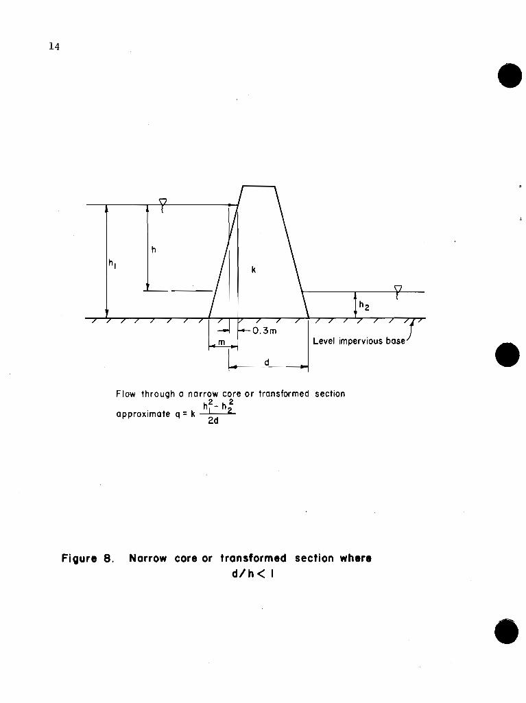
I t i s r e a s o n a b l e t o use t h i s method on t h i n c o r e s e c t i o n s i n e a r t h dams where t h e s l o p e s o f t h e c o r e a r e r e l a t i v e l y s teep . Transformed s e c t i o n s where d / h i s l e s s t h a n one, as shown on F i g u r e 8, a l s o f i t i n t h i s c a t e g o r y .
The seepage q u a n t i t y t h r o u g h an abutment can be e s t i m a t e d by c o n s t r u c t i n g d f l o w n e t i n a t y p i c a l h o r i z o n t a l p l a n e f o r e i t h e r c o n f i n e d o r u n c o n f i n e d f l o w c o n d i t i o n s . D u p u i t ' s assumpt ion has been a p p l i e d t o each f l o w l i n e and e q u a t i o n s w r i t t e n f o r c a l c u l a t i n g d i s c h a r g e t h r o u g h t h e abutment . T h i s s o l u t i o n i s c o n s i d e r e d t h e o r e t i c a l l y c o r r e c t f o r v e r t i - c a l abutments and r e l a t i v e l y a c c u r a t e f o r s l o p i n g abutments. F i g u r e 9 shows an example o f a h o r i z o n t a l f l o w n e t and i n d i c a t e s t h e a p p l i c a b l e e q u a t i o n s f o r c a l c u l a t i n g abutment seepage f o r b o t h v e r t i c a l and s t e e p l y s l o p i n g abutments.
3. Con f ined a q u i f e r o f f i n i t e l e n g t h and u n i f o r m t h i c k n e s s
T h i s method a p p l i e s t o a l a y e r o f permeable m a t e r i a l t h a t i s bounded by a r e l a t i v e l y impermeable l a y e r on t h e bo t tom and by an impermeable s t r u c t u r e o r l a y e r o f g i v e n d imens ion ( d ) on t h e t o p ( see F i g u r e 10) . D a r c y ' s l a w can be a p p l i e d d i r e c t l y when t h e downstream w a t e r l e v e l i s above t h e t o p o f t h e permeable l a y e r . The s o l u t i o n i s l i m i t e d t o t h e r a t e o f d i s c h a r g e f o r t h i s case.
The d i s c h a r g e r a t e can a l s o be c a l c u l a t e d when t h e t a i l - w a t e r l e v e l i s be low t h e t o p o f t h e permeable l a y e r . T h i s i s done by a p p l y i n g D a r c y ' s law and D u p u i t ' s assumpt ion as i n d i c a t e d i n F i g u r e 11.
T h i s method a p p l i e s t o a dam, d i k e , o r d i v e r s i o n s t r u c t u r e t h a t has no c u t o f f t r e n c h and i s c o n s t r u c t e d o v e r a permeable l a y e r . I t can be used f o r any permeable l a y e r w i t h a u n i f o r m t h i c k n e s s t h a t has a d i r e c t i n l e t i n t h e r e s e r v o i r and a d i r e c t o u t l e t downstream f r o m t h e s t r u c t u r e . The permeable l a y e r s a r e o f t e n l o c a t e d t h r o u g h abutments o r t h r o u g h t h e f o u n d a t i o n benea th t h e dam.
4. B l a n k e t - a q u i f e r s i t u a t i o n s
T h i s method has been deve loped f r o m B e n n e t t ' s / p rocedures f o r c a l c u l a t i n g seepage r e l a t i o n s h i p s w i t h n a t u r a l o r c o n s t r u c t e d b l a n k e t s o f r e l a t i v e l y l o w permeable n i a t e r i a1 o v e r p e r v i o u s founda t ions . T h i s method i s used t o ( 1 ) e s t i w a t e seepage q u a n t i t i e s t h r o u g h a n a q u i f e r under an e a r t h dam t h a t i s o v e r l a i n by a b l a n k e t , ( 2 ) e s t i m a t e t h e f a c t o r o f s a f e t y a g a i n s t u p l i f t o f t h e b l a n k e t a t t h e downstream t o e , and ( 3 ) d e t e r m i n e t h e e f f e c t s o f d i s c o n - t i n u o u s b l a n k e t s o r c o n s t r u c t e d upst ream b l a n k e t s .
4/ "The E f f e c t o f B l a n k e t s on Seepage t h r o u g h P e r v i o u s Founda t ions " by P . T . Benne t t , ASCE T r a n s a c t i o n s . V o l . 111, 1946, pp. 215-252.
• It is reasonable to use this method on thin core sectionsin earth dams where the slopes of the core are relativelysteep. Transformed sections where d/h is less than one,as shown on Figure 8, also fit in this category.
13
•
•
The seepage quantity through an abutment can be estimatedby constructing d flow net in a typical horizontal planefor either confined or unconfined flow conditions. Dupuit'sassumption has been applied to each flow line and equationswritten for calculating discharge through the abutment.This solution is considered theoretically correct for vertical abutments and relatively accurate for sloping abutments.Figure 9 shows an example of a horizontal flow net andindicates the applicable equations for calculating abutmentseepage for both vertical and steeply sloping abutments.
3. Confined aquifer of finite length and uniform thickness
This method applies to a layer of permeable material thatis bounded by a relatively impermeable layer on the bottomand by an impermeable structure or layer of given dimension(d) on the top (see Figure 10). Darcy's law can be applieddirectly when the downstream water level is above the topof the permeable layer. The solution is limited to therate of discharge for this case .
The discharge rate can also be calculated when the tailwa ter 1eve1 is below the top of the permeable 1ayer. Th i 5
is done by applying Darcy's law and Dupuit's assumption asindicated in Figure 11.
This method applies to a dam, dike, or diversion 5truc~ure
that has no cutoff trench and is constructed over apermeable layer. It can be used for any permeable layerwith a uniform thickness that has a direct inlet in thereservoir and a direct outlet downstream from the structure.The permeable layers are often located through abutmentsor through the foundation beneath the dam.
4. Blanket-aquifer situations
This method has been developed from Bennett's±! proceduresfor calculating seepage relationships with natural orconstructed blankets of relatively low permeable materialover pervious foundations. This method is used to (1)estimate seepage quantities through an aquifer under anearth dam that is overlain by a blanket, (2) estimate thefactor of safety against uplift of the blanket at thedownstream toe, and (3) determine the effects of discontinuous blankets or constructed upstream blankets .
"The Effect of Blankets on Seepage thY'ough Pervious Foundations"by P. T. Bennett, ASCE Transactions. Vol. III, 1946, pp. 215-252.
I Level impervious base'
Flow through a narrow core o r transformed section hF- h;
approximate q = k 2d
Figure 8. Narrow core or transformed section where d / h < I
14
h
Level impervious base
d
•
•Flow through a narrow core or transformed section
h2 _ h 2approximate q = k 2d 2
FiQure 8. Narrow core or transformed section whered/h< I
•

Flow net on horizontal plane at center of aquifer in abutment
(pion v~ew)
Top of dam 3
US water surface ~n abutment
D.S. water surface . . . . ... . . . ... . . . . .. . . : . . . . . . . . _ . . . . . . .
Base of dam- h 2 - h $ * q = q l 2
aqulfer In Top of dam 7 abutment
1
Base of dom' *q=+ k $ [ q t - : h j
Elevations of near vertical abutment
Top of dom 2
1 U.S. water surface 1 ; h,
D S water surfoce?
p 2 / / / ' / / I / ' / / / / / ,/ , Base of dam- v
Top of dam 7 ~rnperrneable boundary
r = Z r surface
h I I
D S woter surfoce
Bose of dam'
X q = d~scharge In one abutment for each case
4 = shope foctor = Nf / Nd
Elevations of sloping abutment
Figure 9. Abutment seepageusing horizontal flow net From: Course t i t led "~eepocje and ground water f low"
presented by A . Cosogronde of Horvord University
. 15
'tI
confined
aquifer In
abutment
" ,,:'., .
: .".::.: .
water surface
US water surface
I US water surface
Top of dam
D.S water surface-,.---'--
Base of dam
Base of dam
Top of dam------L----------f:.:.. unconfined
..:'. aquifer
::' In abutment
D.S.toeof dam
--Ci.
U. S. toe of dam
Abutment contour atcenter of aQuifer
Imperviousboundary
•
[ I 'Js T s
....
Elevations of near vertical abutment
water surface
l. US water surface
Bose of dam/
Top of dam______-L ~.".....:.:.; .unconflned aquifer
~~~~~~--~f(.<'.:.':in abutment.. "" .
Flow net on horizontal plane atcenter of aquifer in abu1men1
(plan view)
•
Elevations of sloping abutment
Abutment seepage using horizontal flow net
confined aqu Ifer
in abutment
(impermeable boundary
DS water surface
Base of dam /
Top of dam
*q =-+- kf, [2 hi s' - t s' - h2
s,,]
* q =discharge in one abutment for each case
j = shape factor = Nf / Nd
r~ US ~~r surface
ihi
Figure 9.•From: Course titled "Seepage and ground water flow"
presented by A. Casagrande of Harvard University.

r lmpermeable structure
-4 ~lmpermeable base
Compute seepage discharge per foot of length by ~ a r c ~ ' s Law:
Where : k = permeability coefficient of the aquifer
h i= -= hydraulic gradient d
A= t ( I ) =cross sectional area of aquifer
for one foot length ( L = l )
Figure 10 Confined aquifer of finite length with submerged discharge face
( ~ a r c y ' s law)
16
d
aquifer
Impermeable base
•
I
Com pute seepage discharge per foot of length by Darcy sLaw:
q = kiA
Where: k= permeability coefficient of the aquifer
i= += hydraulic gradient
A= t ( I ) =cross sectional area of aquifer
for one foot length ( L =I)
•
Figure 10 Confined aquifer of finite lengthwith submerged discharge face
(Darcy·s law)
•

/ Impermeable structure
Compute discharge per foot of length by the following equation :
v
Where : k = permeability coefficient of the aquifer
L
Figure I I . Combined aquiter of finite length with partially submerged discharge face
( ~ a r c ~ b law 8 ~ u ~ u i t h assumption)
hl aquifer
t n V
t / / / / / / / / / / / / / / / / / / / / U /
d k h 2 4
Level impermeable base
•17
Compute discharge per foot of length by the following equation:
k 2 2q =-( 2 h t- t -h )2d I 2•
d
aquifer
h2
Level impermeable base
•
Where k =permeability coefficient of the aquifer
Figure II. Combined aquifer of finite length with partiallysubmerged discharge face
(Dorey's low a Dupuit', assumption)

Symbols and terms used i n b l a n k e t - a q u i f e r c a l c u l a t i o n s a re shown i n F i gu re 12.
E f f e c t i v e b l a n k e t l eng ths (L1 and L3) a r e c a l c u l a t e d f rom t h e equa t ion :
Pressure head (ho) under t h e b l a n k e t a t t h e downstream t o e c a l c u l a t e d f rom t h e equa t ion :
L?
The c r i t i c a l head ( h c ) beneath t h e b l a n k e t a t t h e downstream t o e i s c a l c u l a t e d f rom t h e equat ion:
The f a c t o r o f s a f e t y r e l a t i v e t o heav ing o f t h e b l a n k e t (Fh) a t t h e downstream t o e i s c a l c u l a t e d f rom t h e equa t ion :
To be s a f e a g a i n s t u p l i f t o r b lowout a s u i t a b l e f a c t o r o f s a f e t y i s needed. A va l ue o f 1.5 t o 2 i s suggested w i t h t h e h i ghe r va lues t o be used on t h e more p i p i n g prone m a t e r i a l s . When unsafe u p l i f t c o n d i t i o n s e x i s t , t h e b e s t s o l u t i o n i s u s u a l l y t o p r o v i d e c o n t r o l l e d d ra inage a t o r under t h e downstream toe.
The q u a n t i t y o f seepage per f o o t o f a q u i f e r i s ob ta ined by app l y i ng Darcy 's law t o t h e perv ious a q u i f e r where t h e i n l e t i s a t t h e e f f e c t i v e l e n g t h o f t h e upstream b l a n k e t and o u t l e t i s a t t h e e f f e c t i v e l e n g t h on t h e downstream s ide . The seepage r a t e i s ob ta ined f rom t h e equa t ion :
B lanke ts and a q u i f e r s a r e o f t e n d iscon t inuous o r hav ing been eroded away i n c e r t a i n l o c a t i o n s . These f a c t o r s can have ext remely adverse e f f e c t s on t h e performance o f t h e b l a n k e t t o c o n t r o l seepage t o accep tab le amounts o r t o p r o v i d e adequate s t a b i l i t y .
18
Symbols and terms used in blanket-aquifer calculations areshown in Figure 12.
Effective blanket lengths (L1 and L3) are calculated fromthe equation:
Ll' L3 = I(kf!kb)(z)(d)
Pressure head (ho) under the blanket at the downstream toecalculated from the equation:
L3h = ho L1 + L2 + L3
The critical head (hc) beneath the blanket at the downstreamtoe is calculated from the equation:
hc = ZYsub./Yw.
The factor of safety relative to heaving of the blanket (Fh)at the downstream toe is calculated from the equation:
Fh = hc/ho
To be safe against uplift or blowout a suitable factor ofsafety is needed. A value of 1.5 to 2 is suggested withthe higher values to be used on the more piping pronematerials. When unsafe uplift conditions exist, the bestsolution is usually to provide controlled drainage at orunder the downstream toe.
The quantity of seepage per foot of aquifer is obtainedby applying Darcy's law to the pervious aquifer where theinlet is at the effective length of the upstream blanketand outlet is at the effective length on the downstreamside. The seepage rate is obtained from the equation:
qf = kf h dL1 + L2 + L3
Blankets and aquifers are often discontinuous or havingbeen eroded away in certain locations. These factors canhave extremely adverse effects on the performance of theblanket to control seepage to acceptable amounts or toprovide adequate stability.
•
•
•

L 3 rl
-
blanket 7 s u b <-
aquifer
impervious N N f l / I N / /
(a) Continuous b l m k e t and aquifer
4 v
- blanket
aquifer / I N / /
impervious /IN//
( b ) D i s c o n t i n u o u s upstream b l a n k e t - c o n t i n u o u s a q u i f e r
L1 = E f f e c t L2 = Length L3 = E f f e c t Lo = Length
i v e l e n g t h o f upstream n a t u r a l b l a n k e t o f embankment base
i v e l e n g t h o f downstream n a t u r a l b l a n k e t o f d i s c o n t i n u o u s upstream b l a n k e t
Net head t o d i s s i p a t e Th ickness o f n a t u r a l b l a n k e t Th ickness o f a q u i f e r Permeabi 1 i t y c o e f f i c i e n t o f b l a n k e t Pernieabi l i t y c o e f f i c i e n t o f a q u i f e r Submerged u n i t w e i g h t o f b l a n k e t P ressu re head under b l a n k e t a t downstream t o e o f dam C r i t i c a l head under b l a n k e t a t downstream t o e o f dam F a c t o r o f s a f e t y r e l a t i v e t o heav ing a t downstream t o e U n i t w e i g h t o f w a t e r (62.4 p c f ) Rate o f d i s c h a r g e t h r o u g h a q u i f e r w i t h u n i t l e n g t h normal t o t h e s e c t i o n .
F i g u r e 12. Symbols and Terms used i n B l a n k e t - A q u i f e r Systems
l19
blanketz
•d aquifer
impervious
(a) Continuous blanket and aquifer
~I
l1llperVlOus
Sl /
h-l I-~ - - - \7.......
~r-/ z blanket
daquifer
I'/~':"fll //~/I //1CV//•(b) Discontinuous upstream blanket - continuous aquifer
•
Effective length of upstream natural blanketLength of embankment baseEffective length of downstream natural blanketLength of discontinuous upstream blanketNet head to dissipateThickness of natural blanketThickness of aquiferPermeability coefficient of blanketPermeability coefficient of aquiferSubmerged unit weight of blanketPressure head under blanket at downstream toe of damCritical head under blanket at downstream toe of damFactor of safety relative to heaving at downstream toeUnit weight of water (62.4 pcf)Rate of discharge through aquifer with unit length normal tothe section.
Figure 12. Symbols and Terms used in Blanket-Aquifer Systems

Blanke ts can be added upon o r be cons t ruc ted comple te ly f rom m a t e r i a l s t h a t have low p e r m e a b i l i t y c h a r a c t e r i s t i c s . Const ructed b lanke ts a r e u s u a l l y compacted. The d i s t a n c e i n t o t h e r e s e r v o i r t o which b l a n k e t i n g i s needed can be determined. A1 1 t he area w i t h i n t h i s 1 i m i t must have a b l a n k e t and an a q u i f e r o f t h e th i ckness and p e r m e a b i l i t y c h a r a c t e r i s t i c s t h a t w i l l n o t exceed t h e assumed c o n d i t i o n s used i n t he c a l c u l a t i o n s .
F i gu re 13 prov ides a s o l u t i o n f o r de te rmin ing t h e e f f e c t i v e l e n g t h o f d i scon t inuous b l anke t s .
It should be noted t h a t i n most b l a n k e t - a q u i f e r r e l a t i o n s h i p s t h e p e r m e a b i l i t y c o e f f i c i e n t s o f t h e b l a n k e t and a q u i f e r a r e en te red as a r a t i o , ( k / k ) . These va lues a r e u s u a l l y r e f e r r e d t o i n terms o f t h i s r a t i o , such as 25, 50, o r 100: Meaning t h a t t he p e r m e a b i l i t y o f t h e a q u i f e r i s 25, 50, o r 100 t imes as g r e a t as t h e p e r m e a b i l i t y o f t h e b l anke t .
The f o l l o w i n g procedure i s recommended f o r de te rmin ing t he l e n g t h t o which a b l a n k e t must be p rov ided i n t h e upstream d i r e c t i o n f rom the t o e o f t h e dam.
Ca l cu la te the p roduc t ( Z ) ( d ) and t h e r a t i o k /kb, then determine L f o r a cont inuous b l a n k e t us i ng f h e equat ion. conse rva t i ve va lue o f kh/kb should be used, i . e . , t he h i g h e s t p robab le r a t i o .
Ca l cu l a te h , hc, and F f rom the g i ven equat ions.
7 6 The va lue o? F should e equal t o o r g r e a t e r than t he minimum va ue e s t a b l i s h e d by c r i t e r i a . I f t h e va lue o f F h i s l e s s than t h e a l l owab le , a d ra inage system may be used, t h e b l a n k e t th i ckness may be increased o r t h e p e r m e a b i l i t y c o e f f i c i e n t o f t h e b l a n k e t may be decreased by compaction.
Ca l cu l a te t he q u a n t i t y o f seepage ( q f ) us i ng t h e app rop r i a t e equa t ion . Compare t h e seepage q u a n t i t y w i t h t he water budget and o t h e r cons ide ra t i ons r e l a t e d t o seepage l oss . I f t h e seepage q u a n t i t y i s excessive, a r e d u c t i o n can be r e a l i z e d by adding t o t h e th i ckness o f t he b l anke t o r by a r e d u c t i o n i n t h e p e r m e a b i l i t y c o e f f i c i e n t o f t he b l a n k e t w i t h a d d i t i o n a l compaction o r o t h e r means. When these methods a r e used, s teps a, b, and c a re repeated be fo re go ing t o s t ep d.
20
Blankets can be added upon or be constructed completely •from materials that have low permeability characteristics.Constructed blankets are usually compacted. The distanceinto the reservoir to which blanketing is needed can bedetermined. All the area within this limit must have ablanket and an aquifer of the thickness and permeabilitycharacteristics that will not exceed the assumed conditionsused in the calculations.
Figure 13 provides a solution for determining the effectivelength of discontinuous blankets.
It should be noted that in most blanket-aquifer relationshipsthe permeabil ity coeffi ci ents of the bl anket and aquifer areentered as a ratio, (kf/k). These values are usuallyreferred to in terms of tRis ratio, such as 25, 50, or 100:Meaning that the permeability of the aquifer is 25, 50, or100 times as great as the permeability of the blanket.
The following procedure is recommended for determining thelength to which a blanket must be provided in the upstreamdirection from the toe of the dam.
a.
b.
c.
Calculate the product (Z)(d) and the ratio kf/k b, thendetermine L1 for a continuous blanket using theequation. A conservative value of kh/kb should beused, i.e., the highest probable ratio.
Calculate ho' hc ' and Fh from the given equations.The value ot Fb should be equal to or greater thanthe minimum value established by criteria. If thevalue of Fh is less than the allowable, a drainagesystem may be used, the blanket thickness may beincreased or the permeability coefficient of theblanket may be decreased by compaction.
Calculate the quantity of seepage (qf) using theappropriate equation. Compare the seepage quantitywith the water budget and other considerations relatedto seepage loss. If the seepage quantity is excessive,a reduction can be realized by adding to the thicknessof the blanket or by a reduction in the permeabilitycoefficient of the blanket with additional compactionor other means. When these methods are used, steps a,b, and c are repeated before going to step d.
•
•

Actual length of discontinuous blanket ( b) , f t
F igure 13. Values of L , and L3for discontinuous natural blankets
•21
2000--:-r-
oo§0 0 0
8 0 0 0 0 0 0 0 0
~0 0008 0 i 0 ~ 0 00 • o. q,
~ID ,.. Ql) CJ)_ N It') In ,.. Ql)CJ)- _.N It')
+-+-llt ~1~: 'L-:I=i=j::: I .. GTC +- . ----tt
40 '·If·+ -n T-4-l=~+:-t'-+- I, '
-, f
-- I
t TI I-
0.002 -r
0.0004
N
-'1:lI--
II
U•0.0003
0.0002
-r -t -oi- r ,- ,
o 0 000000It') ~ In ID,.. Ql) CJ)~
ooN
00000000o 0 0 00000It') ~ In ID ,.. III CJ) o.
o~N
o 0
8 8.,,; ~
Actual length of discontinuous blanket (Lo), ft
•L1,3 = 2cL
c(e °+1)
Fi gure 13. Values of L I and L3
for discontinuous natural blankets

d. I f t he q u a n t i t y o f seepage i s acceptab le , c a l c u l a t e
f a c t o r c = 1
J( kf/ kb) ( Z ) ( d )
e. En te r F i g u r e 13 w i t h va lues o f c and L1 t o o b t a i n Lo which i s t he d i s t a n c e f rom t h e upstream t o e t o where a d i s c o n t i n u i t y i n t h e b l a n k e t w i l l have no e f f e c t on t h e seepage o r u p l i f t values. Th is i s t h e p o i n t beyond which a n a t u r a l b l a n k e t may be removed i n a borrowi ng o p e r a t i on.
I t should be noted t h a t i f d ra inage i s p rov i ded a t t h e downstream toe o r i f a cons t ruc ted b l a n k e t extends o n l y i n t h e upstream d i r e c t i o n , t h e va lue o f L3 i s zero. Th i s method may be used f o r des ign ing a compacted b l a n k e t over a perv ious a q u i f e r t h a t has no n a t u r a l b l anke t . The optimum l e n g t h o f a compacted upstream b l a n k e t f o r t h e purpose o f reduc ing t h e seepage q u a n t i t y can be es t imated
t h e f o l l owing manner.
Assume severa l values o f L ( t h e l e n g t h o f upstream b l a n k e t fo rm t h e upstream t o e o f t h e dam o r t h e co re s e c t i o n o f a zoned embankment.)
Ca l cu l a te c = 1 f rom t h e des ign th icknesses J(k f /kb) ( Z ) ( d )
and p e r m e a b i l i t y r a t e s determined f o r t h e cons t ruc ted b l a n k e t and t h e n a t u r a l a q u i f e r .
En te r F i g u r e 13 w i t h t h e assumed va lues o f Lo and t h e c a l c u l a t e d va lue o f c t o o b t a i n cor responding va lues of L1 f o r each assumed va lue o f Lo.
Ca l cu l a te va lues o f qf f o r t h e values o f L1 (L3 = 0 w i t h no downstream b l anke t ) . P l o t qf vs. Lo. The curve w i l l i n d i c a t e a r a p i d decrease i n q f f o r i n c r e a s i n g va lues o f L up t o a p o i n t where t h e cu rve f l a t t e n s o u t i n d i c a ? i n g an optimum l eng th . The b l a n k e t can be te rmina ted a t any p o i n t where t h e des i r ed r e d u c t i o n i n seepage i s achieved. A d ra inage system i s always recommended near t h e down- stream t o e t o c o n t a i n t he seepage and d i r e c t i t t o t h e stream channel.
22
d. If the quantity of seepage
fa ctor c = -;:;::::;:;::1~~;::::;:::/(kf/kb) (Z) (d)
is acceptable, calculate •e. Enter Figure 13 with values of c and Ll to obtain Lo
which is the distance from the upstream toe to wherea discontinuity in the blanket will have no effect onthe seepage or uplift values. This is the pointbeyond which a natural blanket may be removed in aborrowing operation.
It should be noted that if drainage is provided at thedownstream toe or if a constructed blanket extends onlyin the upstream direction, the value of L3 is zero. Thismethod may be used for designing a compacted blanket overa pervious aquifer that has no natural blanket. Theoptimum length of a compacted upstream blanket for thepurpose of reducing the seepage quantity can be estimatedin the following manner.
a.
b.
Assume several values of Lo (the length of upstreamblanket form the upstream toe of the dam or the coresection of a zoned embankment.)
from the design thicknesses •and permeability rates determined for the constructedblanket and the natural aquifer.
c. Enter Figure 13 with the assumed values of Lo and thecalculated value of c to obtain corresponding valuesof L1 for each assumed value of Lo.
d. Calculate values of qf for the values of L1 (L3 = awith no downstream blanket).
e. Plot qf vs. Lo. The curve will indicate a rapiddecrease in qf for increasing values of L up to apoint where the curve flattens out indica~ing anoptimum length. The blanket can be terminated at anypoint where the desired reduction in seepage is achieved.A drainage system is always recommended near the downstream toe to contain the seepage and direct it to thestream channel.
•

The procedures expla ined above are f o r homogeneous and i s o t r o p i c cond i t i ons w i t h i n the b lanke t and w i t h i n the aqu i fe r . Transformations can be made f o r a s t r a t i f i e d b lanke t (mu1 t i - l a y e r e d ) a s t r a t i f i e d a q u i f e r o r both s t r a t i f i e d b lanket and a q u i f e r .
•
•
•
23
The procedures explained above are for homogeneous andisotropic conditions within the blanket and within theaquifer. Transformations can be made for a stratifiedblanket (multi-layered) a stratified aquifer or bothstratified blanket and aquifer .

•
•
•

APPENDIX A
Appendix A contains examples for the various methods of analysis discussed
•
•
•
APPENDIX A
Appendix A contains examples for thevarious methods of analysis discussed

•
•
•

Fme Sdty Sand k = 30 fpd 6=100 pcf G,= 2.65
" / /' '' / /
[ D e t e r m i n e t h e seepage d i s c h a r g e p e r f o o t o f s t r u c t u r e l e n g t h t h r o u g h t h e f o u n d a t i o n sand l a y e r and check t h e p o t e n t i a l f o r p i p i n g a t t h e downstream t o e .
1. C o n s t r u c t t h e f l o w n e t a c c o r d i n g t o p rocedures i n S o i l Mechanics Note No. 5, and c a l c u l a t e t h e shape f a c t o r $ = Nf/Nd = 3/20 = 0.15 -
2. q = k h $ = 30 f p d (40 f t . ) ( . 1 5 ) = 180 c f s / f t .
3 . C a l c u l a t e d i s c h a r g e g r a d i e n t a t t h e t o e : n h = h/ Fld 40/20 = 2;nl (measured) = 4 f t. ; i d = Ah/Ak = 2/4 = 0.50
4 . C a l c u l a t e c r i t i c a l g r a d i e n t : J = yw ic = vsub.
5. Compare t h e c r i t i c a l g r a d i e n t w i t h t h e d i s c h a r g e g r a d i e n t t o check f o r p i p i n g p o t e n t i a l .
Example 1 F low Ne t - Embankment F o u n d a t i o n
Upstream toe
k= 0.003 fpd
<t of net
IDownstream toe
h=40'
Fine Silty Sandk=30fpd)d=IOO pet
Gs =2.65
I Determine the seepage discharge per foot of structure length through the foundation sand layer and checkthe potential for piping at the downstream toe.
1. Construct the flow net according to procedures in Soil Mechanics Note No.5, and calculate the shapefactor $ = Nf/Nd = 3/20 = 0.15
2. q = k h j = 30 fpd (40 ft.) (.15) = 180 cfs/ft.
3. Calculate discharge gradient at the toe: ~h = hiNd 40/20 = 2;~£ (measured) = 4 ft.;id Ah/~i 2/4 = 0.50
4. Calculate critical gradient: J = Yw i c = ysub.
i c = ysub/yw= Yd/Yw (1 - 1/Gs ) = 100/62.4(1 - 1/2.65) = 1.0.
5. Compare the critical gradient with the discharge gradient to check for piping potential.
Example 1 Flow Net - Embankment Foundation
:poI
N

No
te:
Sin
ce t
he
pe
rme
ab
ilit
y o
f th
e f
ou
nd
ati
on
is
muc
h m
ore
tha
n t
ha
t o
f th
e e
mba
nkm
ent,
Sca
le (
feet
1
co
ns
tru
ct
the
flo
w n
et
for
the
fo
un
da
tio
n o
nly
.
Est
ima
te t
he
dis
cha
rge
to
th
e f
ou
nd
ati
on
dra
in.
Aft
er
su
bd
ivis
ion
, Nf
=
12 a
nd N
d =
44.
N
12
q
= k
h
= 1
00
x 4
0 x
=
1090
cfd
/ft.
o
f da
m
(to
tal
dis
ch
arg
e p
er
ft.)
d
Abo
ut
9.5
flo
w c
ha
nn
els
co
nta
ct
the
dra
in.
9'5
x 1
090
=
860
cfd
/ft.
o
f da
m
len
gth
. D
isch
arg
e t
o t
he
dra
in =
12
Exa
mpl
e 2.
D
isch
arg
e t
o a
dra
in
o<D
k'V 0
Note: Since the permeability of the foundation is much more than that of the embankment,construct the flow net for the foundation only.
Estimate the discharge to the foundation drain.
k= 100 fpd
o 10 20 3040! , ! , ,
Scale (feet)
»I
W
•
After subdivision, Nf = 12 and Nd = 44.
Nf 12q = k h w- = 100 x 40 x 44 = 1090 cfdjft. of dam (total discharge per ft.)
d
About 9.5 flow channels contact the drain.
Discharge to the drain = ~'i x 1090 = 860 cfdjft. of dam length.
Example 2. Discharge to a drain
• •

/ Phreatic line for k,, = k,
Partial flow channel Phreatic line for kh = 16kv (transposed back from Example 3( b ) below)
'Drain ( a ) True section ( isotropic case, kh = k,)
Dete rm ine t h e l o c a t i o n o f t h e p h r e a t i c l i n e and c a l c u l a t e t h e seepage r a t e f o r t h e i s o t r o p i c and a n i s o t r o p i c cases as i n d i c a t e d u s i n g a f l o w n e t .
For i s o t r o p i c case q = k h Nf/Nd = 0.001 x 40 x 3.7112 = 0.012 c f d p e r f o o t o f s t r u c t u r e .
A Note: Horizontal transformation factor=
\/? = \/k = 0.25 kh
Assume k, = 0.001 , kh= 0.016
of structure ( b ) Transformed section (kh = 16kv)
= 0.004 fpd
= 0 . 1 0 7 cfd per foot
Example 3. E f f e c t o f a n i s o t r o p h y o f embankment on t h e p h r e a t i c l i n e
h =40'
Partial flow channel
Phreatic line for kh =ky
Phreatic line for kh = 16ky (transposedbock from Example 3( b) below)
(0) True section (isotropic case, kh = ky)
Determine the location of the phreatic line and calculate the seepage rate for the isotropic and anisotropiccases as indicated using a flow net.
For isotropic case q = k h Nf/Nd = 0.001 x 40 x 3.7/12 = 0.012 cfd per foot of structure.
Note: Horizontal transformation factor =
~= II = 025v~ v~ .
Assume ky=O.OOI, kh=0.016
k'=~ = )0.001 (0.016) = 0.004 fpd
q = kh ~~ = 0.004 (40) (: ) = 0.107 cfd per foot
of structure(b) Transformed section (kh = 16ky)
Example 3. Effect of anisotrophy of embankment on the phreatic line

Piezometric surface along upper flow boundary v
Ground s u r f a c e 1
Scale (feet) h = N, = 13.8; Ah =- 1 2 " = 0.93 ft. "J d 13.8
Uplift pressure 1 Discharge gradient at toewall and transverse sill : Head loss = (Ah x No. drops)
( f t. 1
Point designation
Example 4 . Concre te drop s p i l l w a y - b a s e u p l i f t and d i s c h a r g e g r a d i e n t
No. of drops to point
Tail water
II.s:::.-
Piezometric surface along upper flow boundary
9! ! " T! ! "IfScale (feet)
..'------.~ ..
:.~:r-------'------:-----.------;-----....!...------JL...-....£...---------lo'----
12.8 =0.93 ft13.8 .
Head water:
Ground surface -w--------r=:llo.---------.----+---i':'...:':"I. 10 Lri
'r::',:
Discharge gradient at toewall and transverse sill:Point No. of drops Head loss = Upl ift pre ssuredesignation to point (6h x No. drops) {18.8'- hd.loss )Yw
( ft. ) ( p.s.f.)
A 5.5 5.1 855
B 6.0 5.6 824
C 7.0 6.5 768
D 7.8 7.2 725
E 8.8 8.2 662
F 9.5 8.8 624
i =d0.93= =0.224.2
Example 4. Concrete drop spillway - base uplift and discharge gradient

Step I ----/ v
L embankment k= 1.0 fpd - homogeneous and isotropic 0 m I I c
A
Determine t h e d i s c h a r g e p o i n t o f t h e p h r e a t i c s u r f a c e on t h e downstream f a c e o f t h e dam and t h e seepage q u a n t i t y u s i n g t h e g r a p h i c a l methods and a n a l y t i c a l s o l u t i o n on F i g u r e 3.
1: d=108' -
A . G r a p h i c a l S o l u t i o n :
w Scale (feet)
1. Determine m d i s t a n c e and p l o t Bo = 0.3 m f r o m p o i n t B. 2. F i n d t h e l o c a t i o n s o f p o i n t s 1, 2, 3, and C f o l l o w i n g t h e s teps g i v e n on F i g u r e 3. P o i n t C i s
t h e d i s c h a r g e p o i n t o f t h e p h r e a t i c s u r f a c e . 3. Sca le t h e d i s t a n c e A C = a = 23 f t . 4. Determine a : t a n a = + = 0.5 a = 26.56O 5. C a l c u l a t e seepage d i s c h a r g e = k a s i n 2 a
= 1.0 (23)(.4472)(.4472) = 4.60 c f d / f t . l e n g t h
B. A n a l y t i c a l S o l u t i o n
1. Compute a = - 4d2-h2cot2a = 412564 - 48064 = 22.3 f t .
2. Compute q = k a s i n 2 a = 1 .0(22.3)(.447Z)2 = 4.46 c f d / f t . l e n g t h .
Example 5. P h r e a t i c L i n e - Graph ica l S o l u t i o n
m=60'
Step 4
tep 3
30'
L d= loa'f------------~
A
embankment k= 1.0 fpdhomogeneous and isotropic
k '\/0
o 10 2030 40I I!~Scale (feet)
Determine the discharge point of the phreatic surface on the downstream face of the dam and the seepagequantity using the graphical methods and analytical solution on Figure 3.
A. Graphical Solution:
1. Determine m distance and plot Bo = 0.3 m from point B.2. Find the locations of points 1, 2, 3, and C following the steps given on Figure 3. Point C is
the discharge point of the phreatic surface.3. Scale the distance A C = a = 23 ft.4. Determine a: tan a = ~ = 0.5 a = 26.5605. Calculate seepage discharge k a sin 2a
= 1.0 (23)(.4472)(.4472) = 4.60 cfdjft. length
B. Analytical Solution
1. Compute a = la 2+d 2 - Id 2-h2cot2a = 112564 18064 = 22.3 ft.2. Compute q = k a sin2a = 1.0(22.3){.4472)2 ; 4.46 cfdjft. length.
Example 5. Phreatic Line - Graphical Solution

n
embankment k = 1.0 f pd homogeneous and isotropic
/ k.uo / / / , / / / / /
Pervious drain or filter - 3'thick
Dete rm ine t h e p h r e a t i c s u r f a c e and seepage r a t e p e r f o o t l e n g t h normal t o t h e s e c t i o n t h a t d i scha rges i n t o t h e b l a n k e t d r a i n and compare w i t h example 5 h a v i n g no d r a i n .
1. D e t e r m i n e m = 2 ( 3 3 ) = 6 6 f t . ; 0 . 3 ( 6 6 ) = 1 9 . 8 f t . ; d = 63.8 ft.
2. C a l c u l a t e yo = - d J900 + 4070 - 63.8 = 6.70 f t .
3 . De te rm ine P a r a b o l i c Equa t ion : x = y2 - yo2 = -= 0 . 0 7 4 6 ~ 2 - 3 - 3 5 2 ~ o 2 6.70
4. C a l c u l a t e va lues o f x and y : (y = 6.70, x = 0 ) ; ( y = 12, x = 7 .39) ; (y = 16 , x = 1 5 . 7 ) ; (y = 20, x = 26.5); ( 6 = 24, x = 39.6); ( y = 30, x = 63.8) .
5 . P l o t p a r a b o l a and s k e t c h i n g r e s s t r a n s i t i o n .
6. C a l c u l a t e t h e seepage r a t e : q = k y o = 1 . 0 x 6.70 = 6.70 c f d p e r f o o t o f s t r u c t u r e normal t o t h e c r o s s s e c t i o n .
7 . Compare w i t h Example 5: 6.70 > 4.60. Seepage i n c r e a s e s w i t h d ra inage .
Example 6 . P h r e a t i c L i n e - Embankment w i t h D r a i n
;x:,I
........
m=66'
y
d=63.S'
embankment k = 1.0 f pdhomogeneous and isotropic
Pervious drain or filter - 31thick
o 10 20 30~
Determine the phreatic surface and seepage rate per foot length normal to the section that dischargesinto the blanket drain and compare with example 5 having no drain.
1. Determine m = 2(33) = 66 ft.; 0.3(66) 19.8 ft.; d = 63.8 ft.
0.0746y2 - 3.35Determine Parabolic Equation:
Calculate Yo = /h 2 + d2 - d2.
3.
/900 + 4070 - 63.8 = 6.70 ft.
x = y2 - Yo2 _ y2 - (6.70)2_2yo - 2(6.70) -
4. Calculate values of x and y: (y = 6.70, x = 0); (y = 12, x = 7.39); (y = 16, x = 15.7);(y = 20, x = 26.5); (6 = 24, x= 39.6); (y = 30, x = 63.8).
5. Plot parabola and sketch ingress transition.
6. Calculate the seepage rate: q k Yo = 1.0 x 6.70 = 6.70 cfd per foot of structure normal to thecross section.
7. Compare with Example 5: 6.70 > 4.60. Seepage increases with drainage.
Example 6. Phreatic Line - Embankment with Drain

A d r a i n a g e d i t c h p a r a l l e l s a r i v e r t o i n t e r c e p t s e e p a g e and p r e v e n t r a i s i n g t h e ground water l e v e l i n t h e lower f a rm l a n d . Pumping s t a t i o n s w i l l b e i n s t a l l e d a t 1000 f o o t i n t e r v a l s t o r e t u r n t h e s e e p a g e f l o w s t o t h e r i v e r . Determine t h e needed c a p a c i t y o f e a c h pumping s t a t i o n f o r t h e c o n d i t i o n shown.
1. From F i g u r e 7 q = k h12 - h 2
2 q = 50 (12)2 - ( 2 . 5 ) = 0 .50 (144 - 6 . 2 5 ) = 6 8 . 9 c i d p e r f o o t of l e n g t h 100
2 . Pumping c a p a c i t y i n gpm
68 .9 c f d ( 7 . 4 8 g a l / c u f t ) a = 1440 min/day = 0.358 gpm p e r f o o t o f l e n g t h
f o r 1000-foot l e n g t h : Q = qL = 0.358(1000) = 358 gpm
Example 7 - Unconf ined a q u i f e r w i t h v e r t i c a l i n l e t and o u t l e t f a c e s ( D u p u i t ' s Assumpt ion)
•A-8
II.£
I.
k = 50 fpd
d=50'
hi 2.5'
•A drainage ditch parallels a river to intercept seepage and prevent raisingthe ground water level in the lower farm land. Pumping stations will beinstalled at 1000 foot intervals to return the seepage flows to the river.Determine the needed capacity of each pumping station for the condition shown.
1. From Figure 7 q = k
q 50 (12)2 - (2.5)2100
0.50 (144 - 6.25) 68.9 cfd per foot of length
2. Pumping capacity in gpm
q = 68.9 cfd (7.48 gal/cu ft)1440 min/day = 0.358 gpm per foot of length
for 1000-foot length: Q qL 0.358(1000) 358 gpm
• Example 7 - Unconfined aquifer with vertical inlet and outlet faces(Dupuit1s Assumption)

A 200 f t . l o n g by 50 ft. w ide e x c a v a t i o n i s t o be made para1 1 e l t o a s t ream. S o i l s i n v e s t i g a t i o n r e v e a l e d t h a t a u n i f o r m d e p o s i t o f medium sand, 10 f t . t o 12 f t . t h i c k , o v e r l i e s a c l a y e y s i l t . P e r m e a b i l i t y o f t h e sands ranges from 1 fpd. t o 5 f p d . The c l a y e y s i l t i s r e l a t i v e l y imperv ious . The s t ream l e v e l i s n o r m a l l y be low t h e c o n t a c t between t h e sands and t h e c l a y e y s i l t and groundwater l e v e l s were s l i g h t l y above t h e c o n t a c t . D u r i n g t h e wet season, t h e s t ream may f l o w h a l f f u l l f o r s e v e r a l weeks w i t h o c c a s i o n a l f u l l bank f l o w . The e x c a v a t i o n w i l l ex tend i n t o t h e c l a y e y s i l t . E s t i m a t e d i s c h a r g e i n t o t h e e x c a v a t i o n f o r t h e f u l l bank f l o w c o n d i t i o n s .
E x c a v a t i o n
A- Plan
Ground surface is nearly level
Clay
h, = 12' V r
Scale : 50' Section A-A
k = 5 f p d Sands datum
C o n s t r u c t a f l o w n e t i n p l a n and combine w i t h t h e D u p u i t equa t ion . I n t h i s case, t h e D u p u i t assumpt ion i s v a l i d .
/ Clayey silt v - k < 0.01 fpd
- j h 2 = 0
= c o e f f i c i e n t o f p e r m e a b i l i t y = shape f a c t o r f rom f l o w n e t
hl = sou rce head, above datum h2 = t a i l w a t e r head, above datum
Example 8. Flow t o an E x c a v a t i o n
A-9
A 200 ft. long by 50 ft. wide excavation is to be made parallelto a stream. Soils investigation revealed that a uniform depositof medium sand, 10 ft. to 12 ft. thick, overlies a clayey silt.Permeability of the sands ranges from 1 fpd. to 5 fpd. The clayeysilt is relatively impervious. The stream level is normally belowthe contact between the sands and the clayey silt and groundwaterlevels were slightly above the contact. During the wet season, thestream may flow half full for several weeks with occasional full bankflow. The excavation will extend into the clayey silt. Estimatedischarge into the excavation for the full bank flow conditions.
200'
A~
Excavation ]50'100' Ground surface is
Scale: 1"= 100' nearly level
- ----- ----.~tream --
A-Plan
•
•
Scale: 1"= 50'
-- s:: 0J--rh_,=-~_2~-n-dS---d-a-tu-m-=kh2=~Clayey silt _ .........._--
---Clay
k = 5 fpd----
k < 0.01 fpd
Section A-A
Construct a flow net in plan and combine with the Dupuit equation.In this case, the Dupuit assumption is valid.
k ; coefficient of permeability} = shape factor from flow nethI = source head, above datumh2 = tailwater head, above datum
Example 8. Flow to an Excavation •

Horizontal Flow Net
Nf = 9.5 x 2 = 19
Nd = 4
N 19 $ = - = - =4 .75 d 4
Edge of stream
Plan view I- 9
Scale : I"= 100'
Example 8. Flow to an excavation (cont'd)
•Horizontal Flow Net
Nf: 9.5 x 2 : 19
Nd: 4
:I : ~=_1_9_:475N 4 .
d
k = 5 fpd
A-IQ
II)-oII)
)(
~
•
Edge of stream
Plan view Scale: 1'1: 100'
•Ir
5 x 4.75 x ""2 : 1710 cfd
Example 8. Flow to an excavation (cont'd)

An embankment c o r e w i t h k = 0.1 f p d i s p laced on an imperv ious founda t ion . P e r m e a b i l i t y o f s h e l l m a t e r i a l i s 100 fpd). Determine t h e seepage r a t e th rough t h e c o r e by: ( 1 ) f l o w n e t , ( 2 ) p h r e a t i c l i n e , and ( 3 ) uncon f ined a q u i f e r , Dupui t s Assumption.
1. Flow Net. Shape f a c t o r $ = Nf/Nd = 3/10 = 0.300
q = h k $ = (72 ) (0 .1 ) ( .30 ) = 2.16 c f d pe r f o o t o f l e n g t h
2. P h r e a t i c L i n e : a = - 4d2 - h2cot2a
= 45184 + 17849 - 417849 - 5 1 8 4 ( 1 ) = 151.8 - 112.5 = 39.3 ft.
q = k a s i n 2 a = (0 .1) (39.3) ( .707)( .707) = 1.97 c f d pe r f o o t o f l e n g t h
3. Unconf ined a q u i f e r - D u p u i t ' s Assumption:
h 7 z2 q = k = (0.1) (2) = 1.94 c f d pe r f o o t o f l e n g t h
Example 9.A - Comparat ive Methods, Seepage Through an I s o t r o p i c Embankment Core
A-ll
An embankment core with k = 0.1 fpd is placed on an impervious foundation.Permeability of shell material is 100 fpd i • Determine the seepage rate through •.the core by: (1) flow net, (2) phreatic line, and (3) unconfined aquifer,Dupuits Assumption.
100hcore zonek=O.1 Ipd
;
1. Flow Net. Shape factor ~ = Nf/Nd = 3/10 = 0.300
q = h k ~ = (72)(0.1)(.30) = 2.16 cfd per foot of length
•-OJ..."~
m = 12
IIi:!
d = 133.6'
k=O.IIpd
2. Phreatic Line: a = 1hz + d2 - Id 2 - h2cot2a
- /5184 + 17849 - 117849 - 5184(1) = 151.8 - 112.5 = 39.3 ft.q = k a sin2a = (0.1)(39.3)(.707)(.707) = 1.97 cfd per foot of length
3. Unconfined aquifer - Dupuit's Assumption:h2 722
q = k 2d = (0.1) (2) 133.6 = 1.94 cfd per foot of length
Example 9.A - Comparative Methods, Seepage Through an IsotropicEmbankment Core
•

Same as Example 9A, except t h a t t h e co re m a t e r i a l i s a n i s o t r o p i c ; kv = 0.33 f d and k ~ = 3.0 fpd. Determine t h e seepage r a t e through t h e core by: (!) f l o w ne t , ( 2 ) p h r e a t i c l i n e development does n o t app ly because d/h i s l e s s than 1.0, and ( 3 ) unconf ined a q u i f e r , Dupui ts Assumption.
A l l h o r i z o n t a l d i s tances a r e reduced by a f a c t o r o f = 4113 i 3 = 0.33
C o e f f i c i e n t o f p e r m e a b i l i t y f o r computing d ischarge
k ' = d m ' = d m = 1.0 f p d
F 1 O w N e t Shape f a c t o r $ = - Nf = 5.15 = 0.858 N d
q = k ' h $ = 1 .O(72)( .858) = 61.8 c f d per f o o t o f l e n g t h
2. Ph rea t i c L i n e - does n o t app l y s i n c e h > d.
3. Unconf i n e d a q u i f e r - Dupu i t ' s Assumpti on
58.3 c f d per f o o t o f l e n g t h
Example 9B - Comparative Methods, Seepage Through an A n i s o t r o p i c Embankment Core
•
•
•
A-12
Same as Example 9A, except that the core material is anisotropic;kv = 0.33 fpd and kH = 3.0 fpd. Determine the seepage rate through thecore by: (1) flow net, (2) phreatic line development does not applybecause d/h is less than 1.0, and (3) unconfined aquifer, DupuitsAssumption.
All horizontal distances are reduced by a factor of /kv/k h = /1/3 • 3 = 0.33
Coefficient of permeability for computing discharge
k' = /(kv) kh = /1/3(3) = 1.0 fpd
1 6~hCO" zone
'h' 3 fodky =1/3 tpd
k~o
1. Flow Net
Sh f t t - Nf - 5.15 - 0.858ape ac or f - Nd - -6--- -
q = k' h $ = 1.0(72)(.858) = 61.8 cfd per foot of length
2. Phreatic Line - does not apply since h>d.
'h'3 fod
kv"I/3!0.
3. Unconfined aquifer - Dupuit's Assumption
h2 722
q = k' 2d = (1) (2)44.5 = 58.3 cfd per foot of length
Example 98 - Comparative Methods, Seepage Through an Anisotropic Embankment Core

Tail water level
5
Sandy gravel layer F
Determine the total seepage quantity in cfs through the permeable layer of sandy gravel for a 400-foot long reach of dike having the conditions shown. Calculate the seepage for tailwater levels A and B.
For tailwater level A :
Use Darcy's Law 7 see figure 10
A = (8)(1) = 8 sq. ft.
q = k i A = (500) (0.173) (8) = 692 cfd per foot of length
for 400 it. length Q = q L = 692 (400 ft.)/86,400 sec per day = 3.2 cfs
For tailwater level B:
Use ~ a r c ~ ' s Law and Dupuit's Assumption - see figure I I .
for400 ft. length: Q = q L = 760Cfd (400 ft.)/86,400 sec per day = 3.5 cfs ft
hl = 98 - 40 + 4 = 62 ft.
h = 4 ft.; t = 8 ft. 2
Example 10. Confined aquifer - Finite length
q =
=
(k/2d) (2 hlt - t2 - h22)
(5001600) D(62) (8) - (812 - (4)g = 760 cfd per foot of length
A-13
•EI 9a
Sandy gravel loyer
t =a', k=500 fpd
k =0.001 fpd
d =300'
Determine the total seepage quantity in cfs through the permeable layer ofsandy gravel for a 400-foot long reach of dike having the conditions shown.Calculate the seepage for tailwater levels A and B.
For tailwater level A:
Use Darcy's Law ~ see figure 10
q = k i A
A (8) (1)
i = hid = 52/300 = 0.173
8 sq. ft. •q k i A = (500)(0.173)(8) = 692 cfd per foot of length
for 400 ft. length Q = q L = 692 cf~ (400 ft.)/86.400 sec per day
For tJilwater level B:
Use Darcy's Law and Dupuit's Assumption - see figure II.
3.2 cfs
hl 98 - 40 + 4 62 ft.
h Z 4 ft.; t = 8 ft.
q (k/2d)(2 hlt t 2 - h 2)2
(500/600) ~ (62) (8) (8)2 - (4)~ = 760 cfd per foot of length
for 400 ft. length: Q = q L = 760 cfd (400 ft.)/86.400 sec per day = 3.5 cfsft
Example 10. Confined aquifer - Finite length •

- 0 rr) I I r
t
k, Ysub = 55 pcf k,=0.001 fpd .-
k f = 1.0 fpd
/ / / / / / / / / / / / // / / ' /I // /I /I /I / I / /I /I /I / I /I /I /I / I /I /I / I /I / I / I / // // / I /I
impervious
Determine t h e q u a n t i t y o f seepage ( q f ) pe r f o o t o f embankment l e n g t h and t h e f a c t o r o f s a f e t y r e l a t i v e t o heav ing a t t h e downstream t o e .
1. C a l c u l a t e k f / kb = 11.001 = 1000
2 . C a l c u l a t e L1 = L3 = J ( k f / k b ) ( d ) ( z ) = J ( 1 0 0 0 ) ( 1 0 ) ( 1 2 ) = J120,OOO = 346 f e e t
C a l c u l a t e q f = k f h 3 0 d = l -
L1 + L2 + L3 8 8 2 1 0 = 0.34 c f d p e r f o o t o f s t r u c t u r e
4. C a l c u l a t e h, = h L 3 = 30 346 ~1 + ~ 2 + L~ 346 + 190 + 346 = 30(0.392) = 11.8 f e e t
5 . C a l c u l a t e hc = Z ysubly, = 120 = 10.6 f e e t 62.4
6 . Determine f a c t o r o f s a f e t y , Fh = hc /ho = 10.6 /11.8 = 0.89; unsa fe , p r o v i d e d r a i n a g e a t t o e and r e c a l c u l a t e q f u s i n g L3 = 0.
Example 11. Cont inuous B l a n k e t
kb=0.001 fpdYsub =55 pef
+-----~=----------------------------------~------'-----------~
~
impervious
Determine the quantity of seepage (qf) per foot of embankment length and the factor of safety relative toheaving at the downstream toe.
= 1(1000)(10)(12) = /120,000 = 346 feet
301 882 10 = 0.34 cfd per foot of structure
= 10.6 feet
= 30
1.
2.
3.
4.
5.
Calculate kf/k b = 1/.001 = 1000
Calculate L1 L3 = l(kf/kb)(d)(Z)
Calculate qf kf h d -L1 + L2 + L3 -
Cal cu1ate h0 = h .,----_--,--L_3--,_Ll + L2 + L3
Calculate hc = Z ysub/y = 12(55)w 62.4
346346 + 190 + 346 = 30(0.392) 11.8 feet
6. Determine factor of safety, Fh = hc/ho = 10.6/11.8qf using L3 = O.
0.89; unsafe, provide drainage at toe and recalculate
Example 11. Continuous Blanket

k,=0.001 fpd
p = 3 # [ / .&Y/L-~Y/LV/~/ / //mZY{H/B// /~:Y/H/B/R//
impervious
E s t i m a t e t h e l e n g t h o f t h e compacted b l a n k e t f o r optimum r e d u c t i o n o f q f .
1 - - 1 1. c =
J10 ,OOO(3) ( 2 0 ) = 0.0013
J ( k f l k b ) ( Z ) ( d )
3 . Assume va lues o f Lo, w i t h c = 0.0013, o b t a i n v a l u e s o f L1 f r o m f i g u r e 14. C a l c u l a t e v a l u e s o f q f . - P l o t qf vs . Lo.
4. The optimum l e n g t h o f compacted upstream b l a n k e t appears t o be about 300 f e e t . Then, must whether o r n o t a w a t e r l o s s o f about 11 c f d / f t o f l e n g t h can be t o l e r a t e d .
a s c e r t a i n
3 )O 1000
, ( f t )
0 100 200 300 400 500 900
Lo , f t
Example 12. C o n s t r u c t e d Upstream B l a n k e t
( f t )
0 100 200
290 355 420 635
( f t )
162 262 362
452 517 582 797
(cfd/ft of dan; length)
30.9 19.1 13.8
- -
1 1 . 1 9.7 8.6 6.3
kb=0.001 fpd
Z=3'
d== 20'
"
kf =10 fpd
h=25'
'IIimpervious
Estimate the length of the compacted blanket for optimum reduction of qf.1 1
1 . c = -r/(;=;k=f/~kb~):::;:;(Z~)::::;::(d~) = --;::/l~O:::::;,O~OO~(::;;3);=;(~2O~) = O. 0013
2. qf = kf d h = (lD)(20)(25) = 5000 (L3
= 0)Ll + L2 Ll + 162 L1 + 162
3. Assume values of La, with c = 0.0013, obtain values of L1 from figure 14. Calculate values of qf.Plot qf vs. La·
~-CI 3 O~~-__t----/---t---:---+--____lcQ)
E0 20"Q-0- 10-"--"Q<.J-....
000- 200 400 600 800 1000
Lo ,ft
L o L, L,+ 162_ 5000
qf- L1+162
(ft) (1t) ( ft ) (cfd 1ft of dam length)
0 0 162 30.9
100 100 262 /9.1200 200 362 13.8
300 290 452 I 1.1-- -
400 355 517 9.7500 420 582 8.6900 635 797 6.3
4. The optimum length of compacted upstream blanket appears to be about 300 feet. Then, must ascertainwhether or not a water loss of about 11 cfd/ft of length can be tolerated.
40 ,-----,--.-------,----.------,
Example 12. Constructed Upstream Blanket