Embed Size (px)
Citation preview

1
CS 432 Object-Oriented Analysis and Design
Week 7Component and
Deployment Diagrams

2
Use Case ModelRequirements
Analysis Model
Design Model
DeploymentModel
Implementation
Analysis
Design
Implementation
Test
specified by
Test Model
realized by
distributed by
implemented by
verified by
<<trace>>
<<trace>>
<<trace>>
<<trace>>
<<trace>>
Primary Unified Process Models
Deployment
* From Unified Software Development Process [Jacobson, Booch, & Rumbaugh, 1999]

3
Implementation Workflow
In implementation, we start with the result from design and IMPLEMENT the system in terms of components: Source code Scripts Binaries Executables, and the like…

4
Purposes of Implementation Plan the system integrations required in each iteration
With an incremental approach, implementation takes place in small and manageable steps
Distribute the system by mapping executable components onto nodes in the deployment model.
Based on the active classes found in design Implement the design classes and subsystems found
during design Design classes are implemented as file components that
contain source code Unit test the components, and then integrate them by
compiling them and linking them together into one or more executables
5
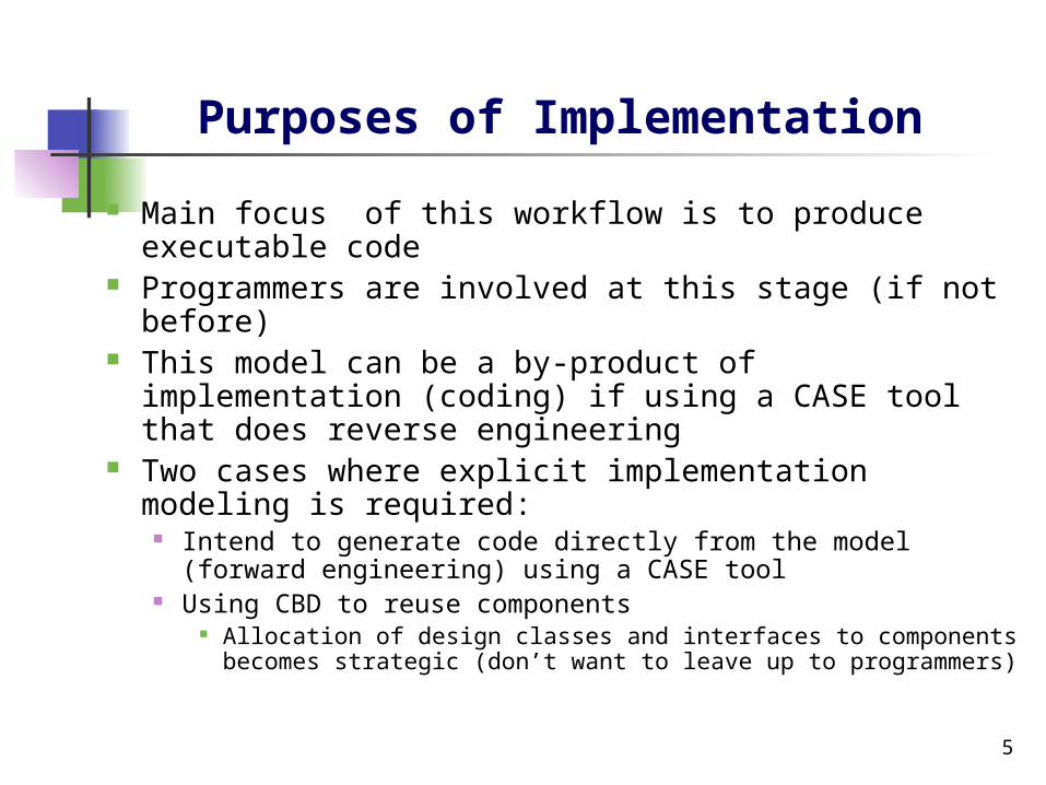
Purposes of Implementation
Main focus of this workflow is to produce executable code
Programmers are involved at this stage (if not before)
This model can be a by-product of implementation (coding) if using a CASE tool that does reverse engineering
Two cases where explicit implementation modeling is required:
Intend to generate code directly from the model (forward engineering) using a CASE tool
Using CBD to reuse components Allocation of design classes and interfaces to components
becomes strategic (don’t want to leave up to programmers)

6
Design Workflow Review

Design to Implementation Subsystems
Class1
Class2
Class3
Class4
Class5
Class6
DLL
«interface»Interfaces
«interface»Interfaces
DLL

Design to Implementation
Implementation componentstrace to design classes.
«traces»
<<compilation>>
<<file>>
Filename.src
<<executable>>
Filename.binInterface
Design Model Implementation Model
Class

9
Implementation Workflow – General

10
Component Diagram
Use UML 2 component diagrams as an architecture-level artifact, either to model the business software architecture, the technical software architecture, or more often than not both of these architectural aspects.
Physical architecture issues, in particular hardware issues, are better addressed via UML deployment diagrams or network diagrams.

11
University Component Diagram

12
Component Diagram
Interfaces and Ports Components may both provide and require
interfaces. An interface is the definition of a collection of
one or more methods, and zero or more attributes
A provided interface is modeled using the lollipop notation and a required interface is modeled using the socket notation.
A port is a feature of a classifier that specifies a distinct interaction point between the classifier and its environment.
Ports are depicted as small squares on the sides of classifiers.

13
Detailed Component Diagram

14
Interesting features to note about this diagram
Ports can be named, such as the Security and Data ports on the Student component.
Ports can support unidirectional communication or bi-directional communication.
The Student component implements three ports, two unidirectional ports and one bi-directional ports. The left-most port is an input port, the Security port is an output port, and the Data port is a bi-directional port.
The StudentAdministration and StudentSchedule interfaces are application specific and may include overlapping method signatures.
You don’t need to use all of the provided interfaces of a component.

15
Component Diagram of a Simple E-Commerce System.

Common Stereotypes for Component Diagrams
Stereotype Indicates
<<application>> A “front-end” of your system, such as the collection of HTML pages and ASP/JSPs that work with them for a browser-based system or the collection of screens and controller classes for a GUI-based system.
<<database>> A hierarchical, relational, object-relational, network, or object-oriented database.
<<document>> A document. A UML standard stereotype.
<<executable>> A software component that can be executed on a node. A UML standard stereotype.
<<file>> A data file. A UML standard stereotype.
<<infrastructure>> A technical component within your system such as a persistence service or an audit logger.
<<library>> An object or function library. A UML standard stereotype.
<<source code>> A source code file, such as a .java file or a .cpp file.
<<table>> A data table within a database. A UML standard stereotype.
<<web service>> One or more web services.
<<XML DTD>> An XML DTD.

17
Creating Component Diagrams –Some Guidelines
Keep components cohesive A component should implement a single, related set of
functionality. This may be the user interface logic for a single user application, business classes comprising a large-scale domain concept, or technical classes representing a common infrastructure concept.
Assign user interface classes to application components.
User interface classes, those that implement screens, pages, or reports, as well as those that implement “glue logic” such as identifying which screen/page/… to display should be placed in components with the application stereotype.
In Java these types of classes would include Java Server Pages (JSPs), servlets, and screen classes implemented via user interface class libraries such as Swing.

18
Creating Component Diagrams – Some Guidelines
Assign technical classes to infrastructure components.
Technical classes, such as those that implement system-level services such as security, persistence, or middleware should be assigned to components which have the infrastructure stereotype.
Assign hierarchies to the same component. 99.9% of the time I find that it makes sense to
assign all of the classes of a hierarchy, either an inheritance hierarchy or a composition hierarchy, to the same component.
19
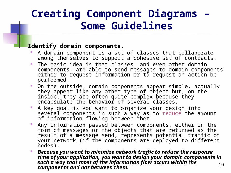
Creating Component Diagrams – Some Guidelines
Identify domain components. A domain component is a set of classes that collaborate among
themselves to support a cohesive set of contracts. The basic idea is that classes, and even other domain
components, are able to send messages to domain components either to request information or to request an action be performed.
On the outside, domain components appear simple, actually they appear like any other type of object but, on the inside, they are often quite complex because they encapsulate the behavior of several classes.
A key goal is you want to organize your design into several components in such a way as to reduce the amount of information flowing between them.
Any information passed between components, either in the form of messages or the objects that are returned as the result of a message send, represents potential traffic on your network (if the components are deployed to different nodes).
Because you want to minimize network traffic to reduce the response time of your application, you want to design your domain components in such a way that most of the information flow occurs within the components and not between them.

Deployment Model – Process Workflow
DeploymentModel
*
Node
Control
Entity
outlinesComponent

21
Deployment Diagram Deployment diagram shows the physical hardware
on which the software system will execute, and how that software is deployed on the hardware
Node - represents a type of hardware such as PC Component represents a type of software such as MS Word Two forms:
Descriptor form Contains nodes, relationships between nodes, and
components General – PC, Software
Instance form Contains node instances, relationships between node
instances, and component instances Specific identifiable piece of hardware or software such as
Jim’s PC or Jim’s MS Word Used to create formal specs for installation

Deployment Model Syntax
SunSolaris
A node represents physical hardware,e.g., a Sun Solaris workstation.
NodeInstance1
A node instance represents a specific piece of hardware, e.g., the host ‘K2’.

Deployment Model Syntax
PC Solaris
<<executable>>Server
<<executable>>Client
Internet[HTTP]
Solaris
<<executable>>Client
Components are deployed on nodes.
Relations between nodes typically depict the communication protocols being used.

24
Deployment Diagram
Deployment diagrams show the hardware for your system, the software that is installed on that hardware, and the middleware used to connect the disparate machines to one another.

25
Class5
Class3
Class4
Class1
Class2 <<file>>abc
«traces»
«traces»
<<traces>>
<<implementation subsystem>>Subystem X
Design Model Implementation Model
A A
<<file>>def
Interface A Interface A
<<implementation subsystem>>Subystem Y
<<design subsystem>>Subsystem X
Both the design andimplementation subsystems support (implement) interface A.
System X supports (implements)interface A,while Subsystem Y uses the interface.
<<file>>ghi
<<file>>jkl
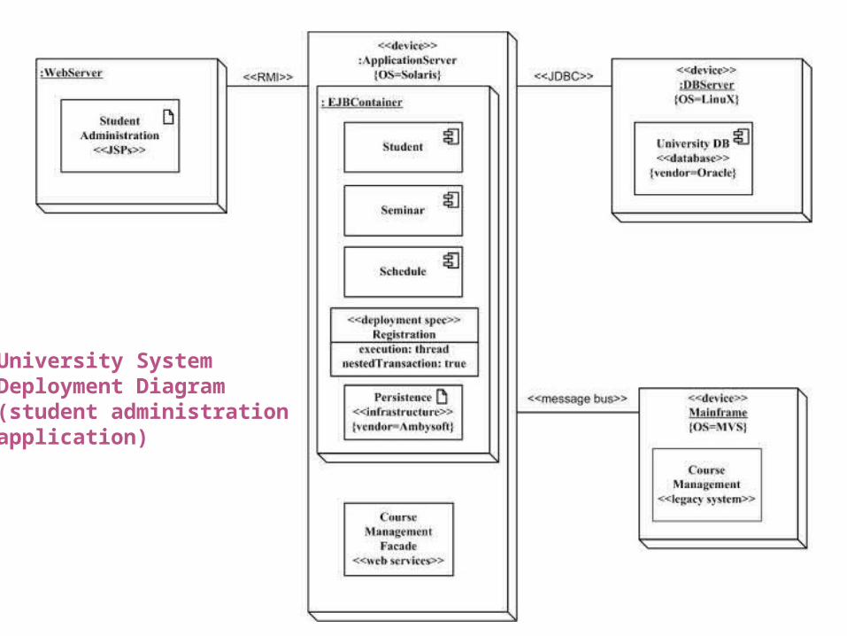
University SystemDeployment Diagram(student administration application)

27
University Deployment Diagram
The three-dimensional boxes represent nodes, either software or hardware. Physical nodes should be labeled with the stereotype device, to indicate that it’s a physical device such as a computer or switch.
Connections between nodes are represented with simple lines, and are assigned stereotypes such as RMI and message bus to indicate the type of connection.
Nodes can contain other nodes or software artifacts. The ApplicationServer node contains EJBContainer (a
software node) which in turn contains three software components, a deployment specification, and a software artifact.
The software components use the same notation as component diagrams

28
Concise UniversityDeployment Diagram
Software elements are now simply listed by their physical filenames, information that developers are very likely to be interested in, and thus a more compact diagram is possible.
29
How to Model the Deployment Architecture for a System
Identify the scope of the model. Does the diagram address how to deploy a version of a
single application or does it depict the deployment of all systems within your organization?
Consider fundamental technical issues. What existing systems will yours need to interact/integrate
with? How robust does your system need to be (will there be
redundant hardware to failover to)? What/who will need to connect to and/or interact with your
system and how will they do it (via the Internet, exchanging data files, and so forth)?
What middleware, including the operating system and communications approaches/protocols, will your system use?
What hardware and/or software will your users directly interact with (PCs, network computers, browsers, and so forth)?
How do you intend to monitor the system once it has been deployed?
How secure does the system need to be (do you need a firewall, do you need to physically secure hardware, and so forth)?
30
How to Model the Deployment Architecture for a System
Identify the distribution architecture. Do you intend to take a fat-client approach where the business
logic is contained in a desktop application or a thin-client approach where business logic is deployed to an application server?
Will your application have two tiers, three tiers, or more? Your distribution architecture strategy will often be predetermined for your application, particularly if you are deploying your system to an existing technical environment.
Identify the nodes and their connections. Your distribution strategy will define the general type of nodes
you will have, but not the exact details. You need to make platform decisions, such as the hardware and
operating systems to be deployed, including how the various nodes will be connected (perhaps via RMI and a message bus).
Distribute software to nodes. Both versions of the deployment diagrams indicate the software
that is deployed on each node, critical information for anyone involved in development, installation, or operation of the system.