Embed Size (px)
Citation preview

1
CONCEPTION OF MINICHANNEL AS THE SOURCE OF SELF-IGNITION AT HIGH SUPERSONIC SPEED
Goldfeld М.А., Starov А.V., Timofeev К.Yu.
Khristianovich Institute of Theoretical and Applied Mechanics
2
Numerous schemeNumerous schemeof fuel injection and flame stabilization of fuel injection and flame stabilization

3
Consecutive fuel jets:
penetration increasing;
producing of stabilization zone;
mixing increasing;
drag decreasing
Wedge-shaped ramp injectors
Aero-ramp
Jacobsen L.S., Gallimore S.D., Schetz J.A., O’Brien W.F.: Goss L.P., “Improved Aerodynamic-Ramp Injector in Supersonic Flow”, AIAA Paper 2001-0518, January 2001
Fuel Injection at High Flight Mach Numbers Fuel Injection at High Flight Mach Numbers

4
AIMS of investigations: Development of concept of the slotted channel (“heat generator”) for ignition of hydrogen and stabilization of combustion under conditions of the supersonic speeds of flow in the combustor (Mach numbers at entrance M=4-6).
Flow calculations in part of combustor with slotted channel for prediction of flow parameters which favorable for hydrogen self-ignition.
Definition of influence of Mach number on change of the flow structure in the main channel, including two variants of slotted channel – with and without critical section.
The subsequent experimental check of effectiveness of ignition of hydrogen in the channel based on predicted distribution of temperature.
5
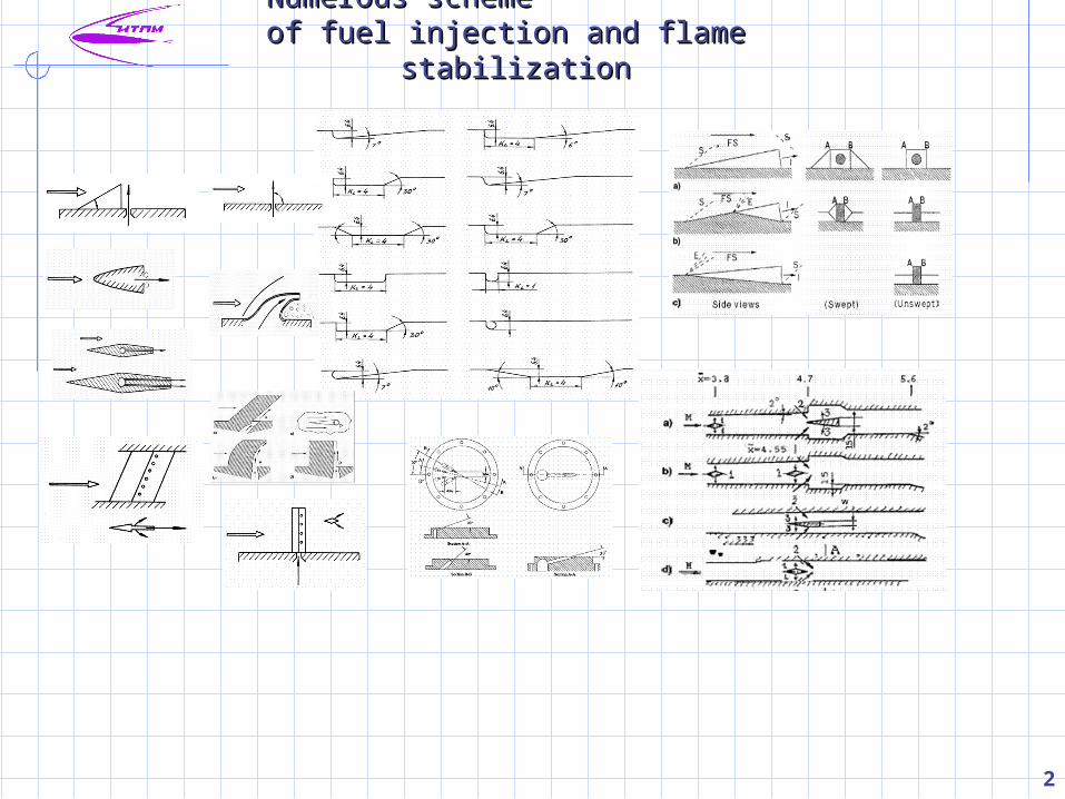
Scheme of combustor part with slotted channel
Combustor model. Attached pipeline operating mode
Experimental parameters at main channel
entrance
М=3.7, 4.9 and 5.8
P0=70 - 270bars
T0=1900 – 2600K

6
Scheme of experimental channel Computational area
Experimental and Calculation Investigations
Calculation parameters at inlet (1):
M=3.7 – static pressure P=1bar, total temperature T0=1960K;M=5.8 – P=0.34bar, T0=2050K
7
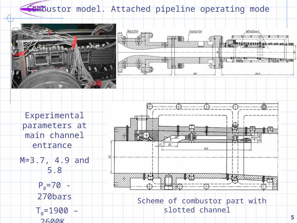
Calculation Results
Flow Features in Slotted Channel

8
Calculation Results
Distributions of static temperature along model channel
0
200
400
600
800
1000
1200
1400
0 0.05 0.1 0.15 0.2 0.25 0.3 0.35x, m
T, Kslotted channel main flow
Static Temperature Increasing in Slotted Channel
0
200
400
600
800
1000
1200
1400
0 0.05 0.1 0.15 0.2 0.25 0.3 0.35x, m
T, Kslotted channel main flow
M=3.7, without geometrical throat
0
300
600
900
1200
1500
1800
0 0.05 0.1 0.15 0.2 0.25 0.3 0.35x, m
T, K slotted channel main flow
M=5.8, without geometrical throat
M=5.8, with geometrical throat
9
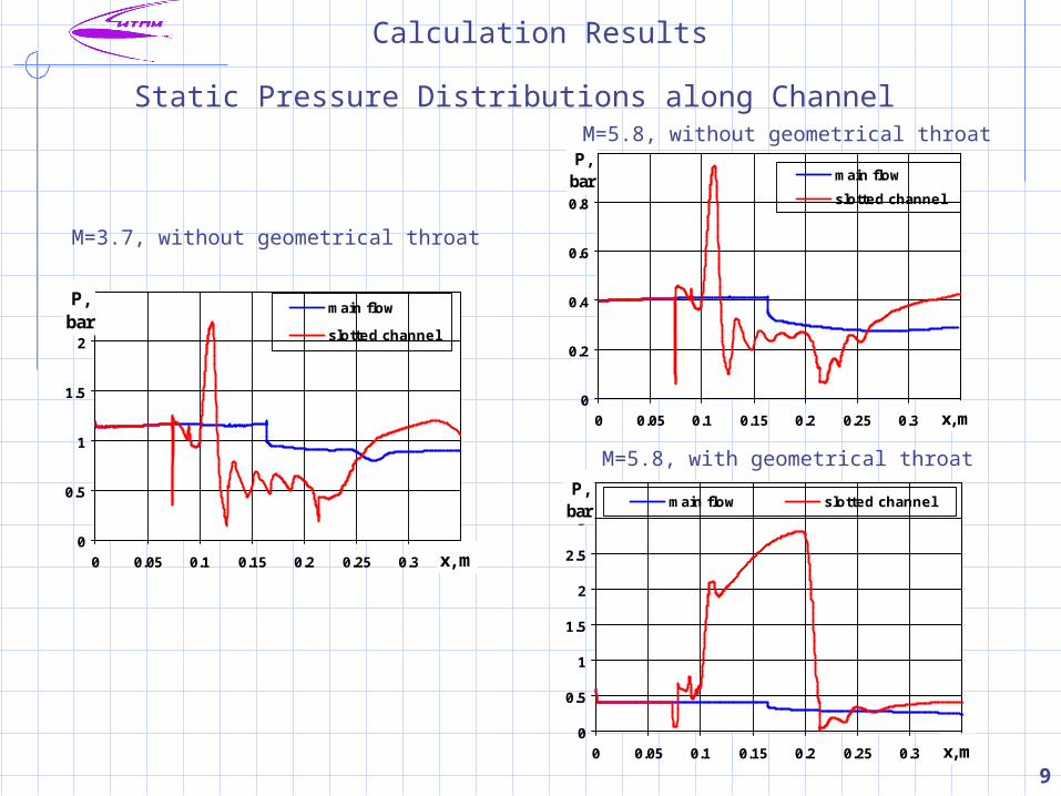
Calculation Results
Static Pressure Distributions along Channel
0
0.5
1
1.5
2
2.5
0 0.05 0.1 0.15 0.2 0.25 0.3 0.35x, m
P,bar
main flow
slotted channel
0
0.2
0.4
0.6
0.8
1
0 0.05 0.1 0.15 0.2 0.25 0.3 0.35x, m
P,bar main flow
slotted channel
M=3.7, without geometrical throat
M=5.8, without geometrical throat
M=5.8, with geometrical throat
0
0.5
1
1.5
2
2.5
3
3.5
0 0.05 0.1 0.15 0.2 0.25 0.3 0.35x, m
P,bar main flow slotted channel

10
Experiment and Calculation Comparison at M=3.7 w/o geometrical throat
Schlieren and computational visualization of density field
Schlieren
Calculation
11
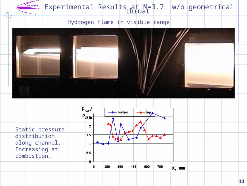
Experimental Results at M=3.7 w/o geometrical throat
Hydrogen flame in visible range
0
0.5
1
1.5
2
2.5
3
0 150 300 450 600 750 900
bottom top
xmm
Phot/ Pcold
Static pressure distribution along channel. Increasing at combustion.
12
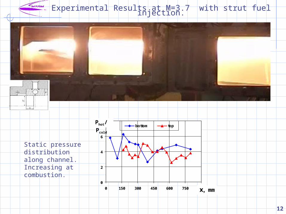
Experimental Results at M=3.7 with strut fuel injection.
Hydrogen flame in visible range
0
2
4
6
8
0 150 300 450 600 750 900
bottom top
xmm
Phot/ Pcold
Static pressure distribution along channel. Increasing at combustion.
13
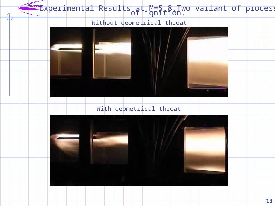
Experimental Results at M=5.8.Two variant of process of ignition.
Without geometrical throat
With geometrical throat

14
Experimental Results at M=4.9. Slotted channel modification.
Hydrogen flame in visible range
0
0.5
1
1.5
2
2.5
3
3.5
0 150 300 450 600 750 900
bottom top
xmm
Phot/ Pcold
Static pressure distribution along channel. Increasing at combustion.
15
Conclusions
Numerical simulation of flow in the channel of the combustion chamber has shown that in the slotted channel a deceleration of airflow and considerable increase of static temperature and heat flux is observed.
Depending on internal geometry of the slotted channel (without or with a geometrical throat at the exit section) is realized a supersonic or subsonic flow, accordingly. In both cases, increase of temperature together with high level enough of static pressure in the channel leads to hydrogen self-ignition in the slotted channel and to propagation of combustion into flow core of the main channel that was confirmed by the experimental results.
The mechanism of combustion stabilization in these two cases was different.
In the first case, the hot flow of products of combustion from a nozzle of the slotted channel extends into the main stream, and it leads to combustion propagation into the main channel behind shock wave area.
In the second case, chocking of the slotted channel leads to emission of the combustion products before an entrance. As a result, mass and heat transfer between the slotted and main flow also intensifies and the further stabilization of combustion begins in the region of the attached shock wave in recirculation area and behind the entrance of the slotted channel.