Embed Size (px)
Citation preview

1
An Introduction to
Computer NetworksComputer Networks
University of TehranDept. of EE and Computer Engineering
By:Dr. Nasser Yazdani
Lecture 6: Wirless NetworksWirless Networks

Univ. of TehranIntroduction to computer
Network 2
OutlineOutline
Why wireless Networks What is special on wireless
networks Challenges Bluetooth Zigbee 802.11 802.11 mac

Why wireless networks? Mobility: to support mobile applications Costs: reductions in infrastructure and
operating costs: no cabling or cable replacement
Special situations: No cabling is possible or it is very expensive.
Reduce downtime: Moisture or hazards may cut connections.

Why wireless networks? (cont)
Rapidly growing market attests to public need for mobility and uninterrupted access
Consumers are used to the flexibility and will demand instantaneous, uninterrupted, fast access regardless of the application.
Consumers and businesses are willing to pay for it

Univ. of Tehran Introduction to computer Network
0
100
200
300
400
500
600
700
1993 1994 1995 1996 1997 1998 1999 2000 2001
The Two Hottest Trends inTelecommunications Networks
Source: Ericsson Radio Systems, Inc.
Mobile TelephoneUsers
Internet Users
Millions
Year

Growth of Home wireless

Why is it so popular? Flexible Low cost Easy to deploy Support mobility

Applications ? Ubiquitous, Pervasive computing or
nomadic access. Ad hoc networking: Where it is difficult
or impossible to set infrastructure. LAN extensions: Robots or industrial
equipment communicate each others. Sensor network where elements are two many and they can not be wired!.
Sensor Networks: for monitoring, controlling, e
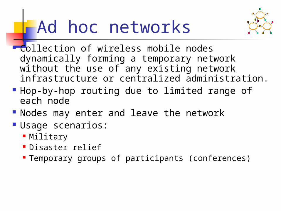
Ad hoc networks Collection of wireless mobile nodes dynamically
forming a temporary network without the use of any existing network infrastructure or centralized administration.
Hop-by-hop routing due to limited range of each node
Nodes may enter and leave the network Usage scenarios:
Military Disaster relief Temporary groups of participants (conferences)

Sensor networks Deployment of small, usually wireless sensor
nodes. Collect data, stream to central site Maybe have actuators
Hugely resource constrained Internet protocols have implicit
assumptions about node capabilities Power cost to transmit each bit is very high
relative to node battery lifetime Loss / etc., like other wireless Ad-hoc: Deployment is often somewhat
random

Summary Need to be connected from
everywhere and anytime. Need to be connected on
movement Need to good quality service on
those situation. Interworking with the existing
networks

Classification of Wireless Networks
Mobility: fixed wireless or mobile Analog or digital Ad hoc (decentralized) or centralized
(fixed base stations) Services: voice (isochronous) or data
(asynchronous) Ownership: public or private
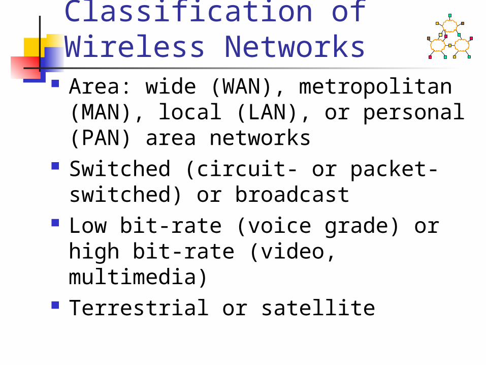
Classification of Wireless Networks
Area: wide (WAN), metropolitan (MAN), local (LAN), or personal (PAN) area networks
Switched (circuit- or packet-switched) or broadcast
Low bit-rate (voice grade) or high bit-rate (video, multimedia)
Terrestrial or satellite

What is special on wireless?
Mobility in the network elements Very diverse applications/devices. Connectivity and coverage
(internetworking) is a problem. Maintaining quality of service over very
unreliable links Security (privacy, authentication,...) is
very serious here. Broadcast media. Cost efficiency
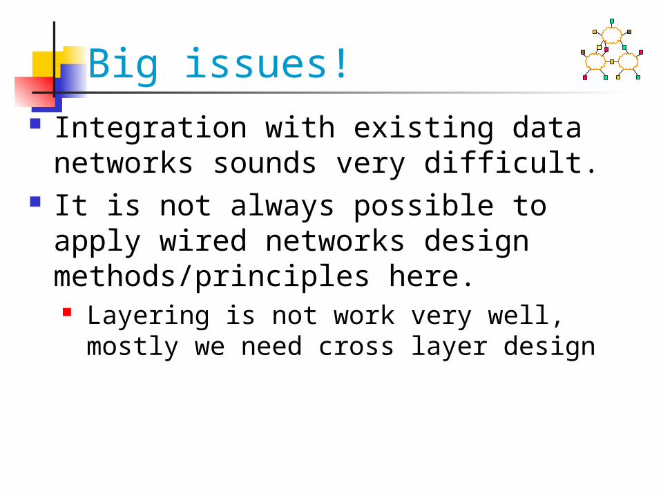
Big issues! Integration with existing data networks
sounds very difficult. It is not always possible to apply wired
networks design methods/principles here. Layering is not work very well, mostly we
need cross layer design

Wireless Differences 1 Physical layer: signals travel in open
space Subject to interference
From other sources and self (multipath) Creates interference for other
wireless devices Noisy lots of losses Channel conditions can be very
dynamic

Wireless Differences 2 Need to share airwaves rather than wire
Don’t know what hosts are involved Hosts may not be using same link
technology Interaction of multiple transmitters at
receiver Collisions, capture, interference
Use of spectrum: limited resource. Cannot “create” more capacity very easily More pressure to use spectrum efficiently

Wireless Differences 3 Mobility
Must update routing protocols to handle frequent changes
Requires hand off as mobile host moves in/out range
Changes in the channel conditions. Coarse time scale:
distance/interference/obstacles change
Other characteristics of wireless Slow

Growing Application Diversity
Relay Node
Access Point
Sensor
Wired Internet
Ad-Hoc/Sensor Networks
Collision Avoidance:Car Networks
Wireless Home Multimedia
Mesh Networks

Challenge: Diversity
New architectures must accommodate rapidly evolving technology
Must accommodate different optimization goals Power, coverage, capacity, price
INTERNETINTERNET
WirelessEdge
Network
WirelessEdge
Network
INTERNETINTERNET
20052010
WirelessEdge
Network
WirelessEdge
Network
Other Challenges Performance: Nothing is really work
well Security: It is a broadcast media Cross layer interception
TCP performance

Univ. of Tehran Computer Network 23
Ideal Wireless Area network?
Wish List High speed (Efficiency) Low cost No use/minimal use of the mobile
equipment battery Can work in the presence of other WLAN
(Heterogeneity) Easy to install and use Etc

Univ. of Tehran Computer Network 24
Wireless LAN Design Goals
Wireless LAN Design Goals Portable product: Different countries
have different regulations concerning RF band usage.
Low power consumption License free operation Multiple networks should co-exist
Univ. of Tehran Computer Network 25
Wireless LAN Design Alternatives
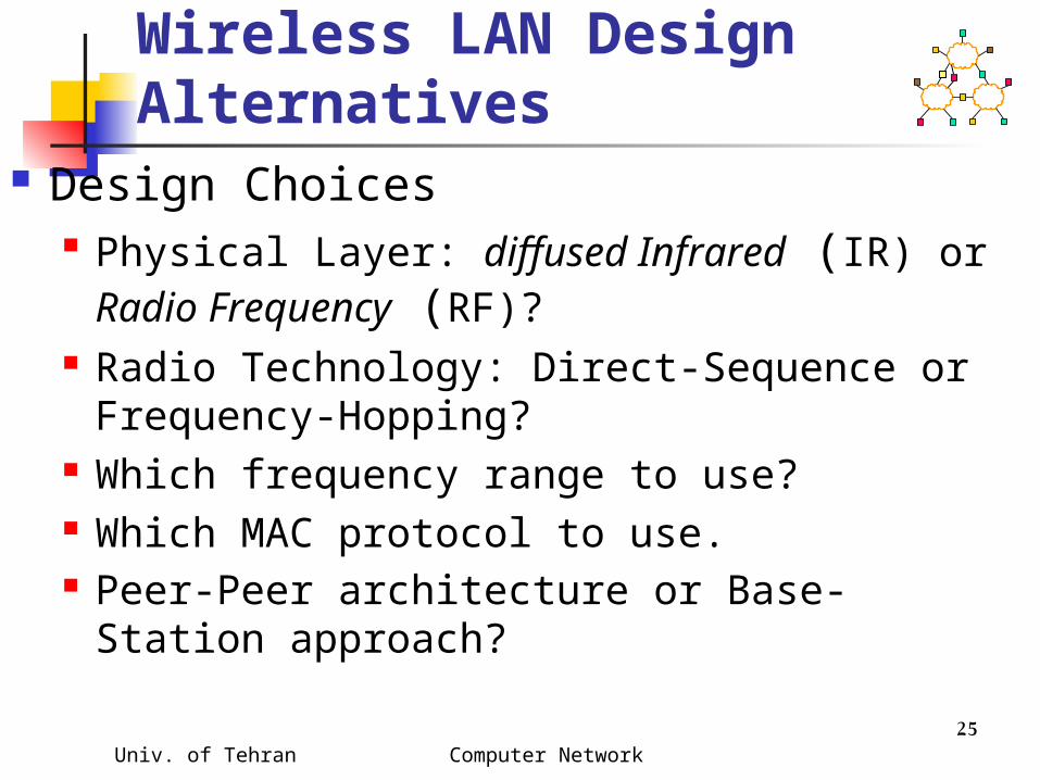
Design Choices Physical Layer: diffused Infrared (IR) or
Radio Frequency (RF)? Radio Technology: Direct-Sequence or
Frequency-Hopping? Which frequency range to use? Which MAC protocol to use. Peer-Peer architecture or Base-Station
approach?

DSSS DSSS (Direct Sequence Spread (Direct Sequence Spread Spectrum)Spectrum)
XOR of the signal with pseudo-random number (chipping sequence) generate a signal
with a wider range of frequency: spread spectrum
user data
chipping sequence
resultingsignal
0 1
0 1 1 0 1 0 1 01 0 0 1 11
XOR
0 1 1 0 0 1 0 11 0 1 0 01
=
tb
tc
tb: bit periodtc: chip period

Univ. of Tehran Computer Network 27
Radio Technology Spread Spectrum Technologies
Frequency Hopping: The sender keeps changing the carrier wave frequency at which its sending its data. Receiver must be in synch with transmitter, and know the ordering of frequencies.
Direct-Sequence: The receiver listens to a set of frequencies at the same time. The subset of frequencies that actually contain data from the sender is determined by spreading code, which both the sender and receiver must know. This subset of frequencies changes during transmission.
Non-Spread Spectrum requires licensing

Univ. of Tehran Computer Network 28
Wireless StandardsWireless Standards

Univ. of Tehran Computer Network 29
Distance vs. Data RateDistance vs. Data Rate

Univ. of Tehran Computer Network 30
Bluetooth Goals
Ad-hoc wireless connectivity for everything!
Original goal Low-cost replacement for annoying wire
between cellphone and headset Result: Two modes of operation
Point to point (serial wire replacement) Point to multipoint (ad-hoc networking)

Univ. of Tehran Computer Network 31
Bluetooth devices Cellphones Headsets PDAs Laptops Two-way pagers Pads, tabs, etc…

Univ. of Tehran Computer Network 32
Bluetooth design Specs Started with Ericsson's Bluetooth Project in 1994 ! Named after Danish king Herald Blatand (AD 940-
981) who was fond of blueberries Radio-frequency communication between cell
phones over short distances Intel, IBM, Nokia, Toshiba, and Ericsson formed
Bluetooth SIG in May 1998 Version 1.0A of the specification came out in late
1999. IEEE 802.15.1 approved in early 2002 is based on
Bluetooth Key Features:
Lower Power: 10 μA in standby, 50 mA while transmitting Cheap: $5 per device Small: 9 mm2 single chips

Univ. of Tehran Computer Network 33
Bluetooth design Specs Frequency Range: 2402 - 2480 MHz (total 79
MHz band) 23 MHz in some countries, e.g., Spain Data Rate:1 Mbps (Nominal) 720 kbps (User) Channel Bandwidth:1 MHz Range: Up to 10 m can be extended further RF hopping: 1600 times/s => 625 μs/hop Security: Challenge/Response Authentication.
128b Encryption TX Output Power:
Class 1: 20 dBm Max. (0.1W) – 100m Class 2: 4 dBm (2.5 mW) Class 3: 0 dBm (1mW) – 10m

Univ. of Tehran Computer Network 34
Piconet Piconet is formed by a master and many
slaves Up to 7 active slaves. Slaves can only transmit
when requested by master Up to 255 Parked slaves
Active slaves are polled by master for transmission
Each station gets a 8-bit parked address => 255 parked slaves/piconet
The parked station can join in 2ms. Other stations can join in more time. A device can participate in multiple
piconets => complex schedule

Univ. of Tehran Computer Network 35
Bluetooth Operational States

Univ. of Tehran Computer Network 36
Bluetooth Operational States (Cont)
Standby: Initial state Inquiry: Master sends an inquiry packet. Slaves
scan for inquiries and respond with their address and clock after a random delay (CSMA/CA)
Page: Master in page state invites devices to join the piconet. Page message is sent in 3 consecutive slots (3 frequencies). Slave enters page response state and sends page response including its device access code.
Master informs slave about its clock and address so that slave can participate in piconet. Slave computes the clock offset.
Connected: A short 3-bit logical address is assigned Transmit:

Univ. of Tehran Computer Network 37
Bluetooth Packet Format
Packets can be up to five slots long. 2745 bits. Access codes:
Channel access code identifies the piconet Device access code for paging requests and response Inquiry access code to discover units
Header: member address (3b), type code (4b), flow control, ack/nack (1b), sequence number, and header error check (8b) 8b Header is encoded using 1/3 rate FEC resulting in 54b
Synchronous traffic has periodic reserved slots. Other slots can be allocated for asynchronous
traffic54b 0-2754bAccess
CodeBaseband/link Control Header Data
Payload
72b

Univ. of Tehran Computer Network 38
Bluetooth Energy Management
Three inactive states: Hold: No ACL. SCO (Sync data) continues. Node
can do something else: scan, page, inquire Sniff: Low-power mode. Slave listens only after
fixed sniff intervals. Park: Very Low-power mode. Gives up its 3-bit
active member address and gets an 8-bit parked member address.
Packets for parked stations are broadcast to 3-bit zero address.
Sniff

Univ. of Tehran Computer Network 39
Bluetooth Protocol Stack
RF = Frequency hopping GFSK modulation Baseband: Frequency hop selection,
connection, MAC

Univ. of Tehran Computer Network 40
Baseband Layer Each device has a 48-bit IEEE MAC address 3
parts: Lower address part (LAP) – 24 bits Upper address part (UAP) – 8 bits Non-significant address part (NAP) - 16 bits
UAP+NAP = Organizationally Unique Identifier (OUI) from IEEE
LAP is used in identifying the piconet and other operations
Clock runs at 3200 cycles/sec or 312.5 μs (twice the hop rate)

Univ. of Tehran Computer Network 41
Bluetooth Protocol Stack
Logical Link Control and Adaptation Protocol (L2CAP) Protocol multiplexing Segmentation and reassembly Controls peak bandwidth, latency, and delay variation
Host Controller Interface RFCOMM Layer:
Presents a virtual serial port Sets up a connection to another RFCOMM
Service Discovery Protocol (SDP): Each device has one SDP which acts as a server and client for service discovery messages
IrDA Interoperability protocols: Allow existing IrDA applications to work w/o changes

Univ. of Tehran Computer Network 42
Bluetooth Protocol Stack
IrDA object Exchange (IrOBEX) and Infrared Mobile Communication (IrMC) for synchronization
Audio is carried over 64 kbps over SCO links over baseband
Telephony control specification binary (TCS-BIN) implements call control including group management (multiple extensions, call forwarding, and group calls)
Application Profiles: Set of algorithms, options, and parameters. Standard profiles: Headset, Cordless telephony, Intercom, LAN, Fax, Serial line (RS232 and USB).
Univ. of Tehran Computer Network 43
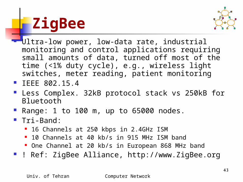
ZigBee Ultra-low power, low-data rate, industrial monitoring
and control applications requiring small amounts of data, turned off most of the time (<1% duty cycle), e.g., wireless light switches, meter reading, patient monitoring
IEEE 802.15.4 Less Complex. 32kB protocol stack vs 250kB for
Bluetooth Range: 1 to 100 m, up to 65000 nodes. Tri-Band:
16 Channels at 250 kbps in 2.4GHz ISM 10 Channels at 40 kb/s in 915 MHz ISM band One Channel at 20 kb/s in European 868 MHz band
! Ref: ZigBee Alliance, http://www.ZigBee.org

Univ. of Tehran Computer Network 44
ZigBee
Two types of devices:Full Function Devices (FFD) for network routing and link coordinationReduced Function Devices (RFD): Simple send/receivedevices
Univ. of Tehran Computer Network 45
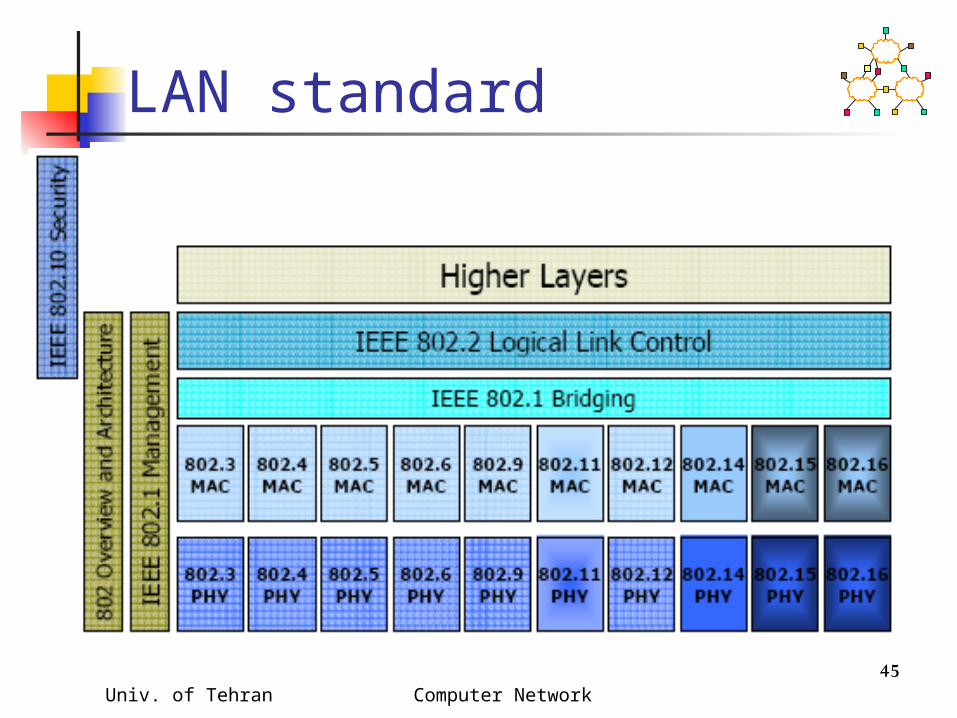
LAN standard

Univ. of Tehran Computer Network 46
Early Experiences IBM Switzerland,Late 1970
Factories and manufacturing floors Diffused IR technology Could not get 1 Mbps
HP Labs, Palo Alto, 1980 100 Kbps DSSS around 900 Mhz CSMA as MAC Experimental licensing from FCC Frequency administration was problematic, thus
abandoned Motorola, ~1985
1.73 GHz Abandoned after FCC difficulties

Univ. of Tehran Computer Network 47
Architectures
Distributed wireless Networks: also called Ad-hoc networks
Centralized wireless Networks: also called last hop networks. They are extension to wired networks.
Univ. of Tehran Computer Network 48
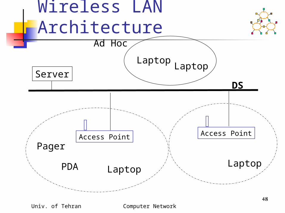
Wireless LAN Architecture
Server
PDA Laptop
LaptopLaptop
Laptop
Access Point Access Point
Ad Hoc
Pager
DS

Univ. of Tehran Computer Network 49
Access Point Functions Access point has three components
Wireless LAN interface to communicate with nodes in its service area
Wireline interface card to connect to the backbone network
MAC layer bridge to filter traffic between sub-networks. This function is essential to use the radio links efficiently

Univ. of Tehran Computer Network 50
Medium Access Control
Wireless channel is a shared medium
Need access control mechanism to avoid interference
MAC protocol design has been an active area of research for many years. See Survey.
Univ. of Tehran Computer Network 51
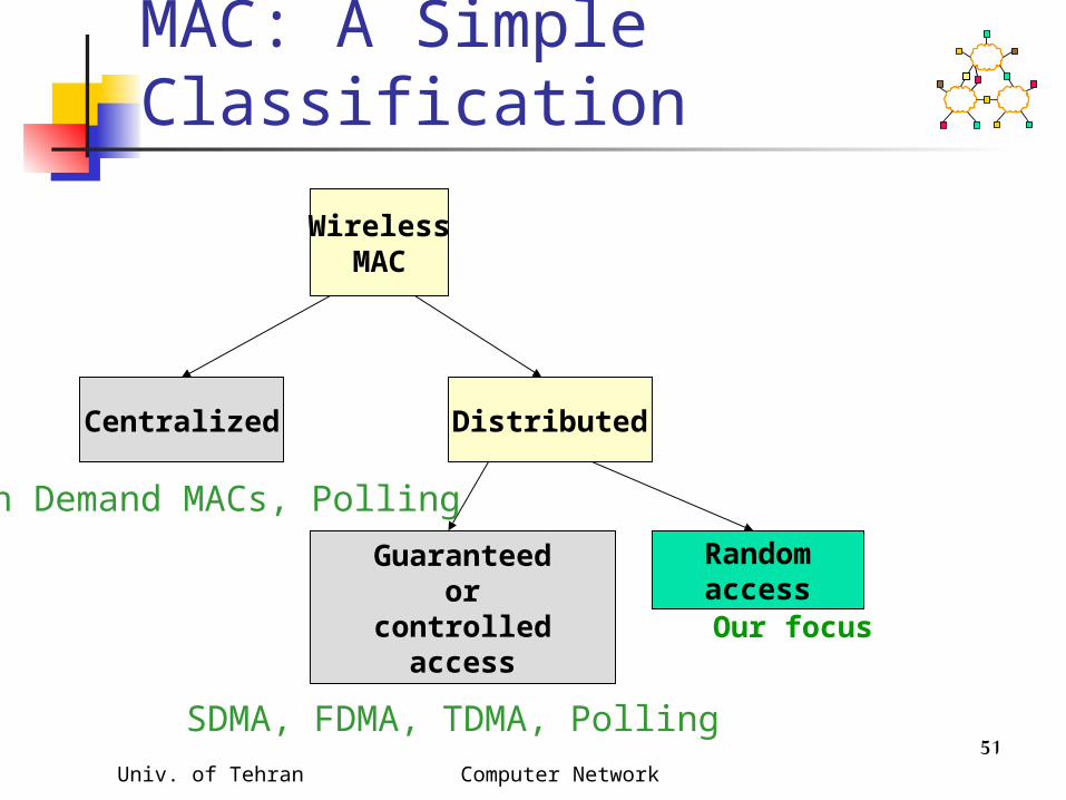
MAC: A Simple Classification
WirelessMAC
Centralized Distributed
Guaranteedor
controlledaccess
RandomaccessOur focus
SDMA, FDMA, TDMA, Polling
On Demand MACs, Polling

Univ. of Tehran Computer Network 52
Wireless MAC issues Half duplex operations: difficult to receive
data while sending Time varying channel: Multipath propagation,
fading Burst Channel error: BER is as high as 10-3.
We need a better strategy to overcome noises.
Location dependant carrier sensing: signal decays with path length. Hidden nodes Exposed nodes Capture: when a receiver can cleanly receive data
from two sources simultaneously, the farther one sounds a noise.

Univ. of Tehran Computer Network 53
Performance Metrics Delay: ave time on the MAC queue Throughput: fraction used for data
transmission. Fairness: Not preference any node Stability: handle instantaneous loads
greater than its max. capacity. Robust against channel fading Power consumption: or power saving Support for multimedia

Univ. of Tehran Computer Network 54
Wireless LAN Architecture, Cont…
Logical Link Control Layer
MAC Layer: Consist of two sub layer, physical Layer and physical convergence layer
Physical convergence layer, shields LLC from the specifics of the physical medium. Together with LLC it constitutes equivalent of Link Layer of OSI

Univ. of Tehran Computer Network 55
Power Management Battery life of mobile
computers/PDAs are very short. Need to save
The additional usage for wireless should be minimal
Wireless stations have three states Sleep Awake Transmit

Univ. of Tehran Computer Network 56
Power Management, Cont…
AP knows the power management of each node
AP buffers packets to the sleeping nodes AP send Traffic Delivery Information
Message (TDIM) that contains the list of nodes that will receive data in that frame, how much data and when?
The node is awake only when it is sending data, receiving data or listening to TDIM.

Univ. of Tehran Computer Network 57
802.11 Features Power management: NICs to switch
to lower-power standby modes periodically when not transmitting, reducing the drain on the battery. Put to sleep, etc.
Bandwidth: To compress data Security: Addressing: destination address does
not always correspond to location.

Univ. of Tehran Computer Network 58
IEEE 802.11 Topology Independent basic service set (IBSS) networks (Ad-
hoc) Basic service set (BSS), associated node with an AP Extended service set (ESS) BSS networks Distribution system (DS) as an element that
interconnects BSSs within the ESS via APs.

Univ. of Tehran Computer Network 59
ESS topology connectivity between multiple BSSs, They use
a common DS

Univ. of Tehran Computer Network 60
802.11 Logical Architecture
•PLCP: Physical Layer Convergence Procedure•PMD: Physical Medium Dependent•MAC provides asynchronous, connectionless service•Single MAC and one of multiple PHYs like DSSS, OFDM, IR and FHSS.

Univ. of Tehran Computer Network 61
802.11 MAC Frame Format
FrameControl
Duration Addr 1
ProtocolVersion
Type Sub type To DS
FromDS
RetryLastFragment
RSVDEPPower Mgt
CRCSequenceControl
User Data
Address 4Addr 2 Addr 3
MAC Header
Encrypted to WEP
Preamble PLCP header
MPDU
Bytes 32 6 34~2346
22 66Bytes 26 6 4
2Bits 2 4 1 11
Univ. of Tehran Computer Network 62
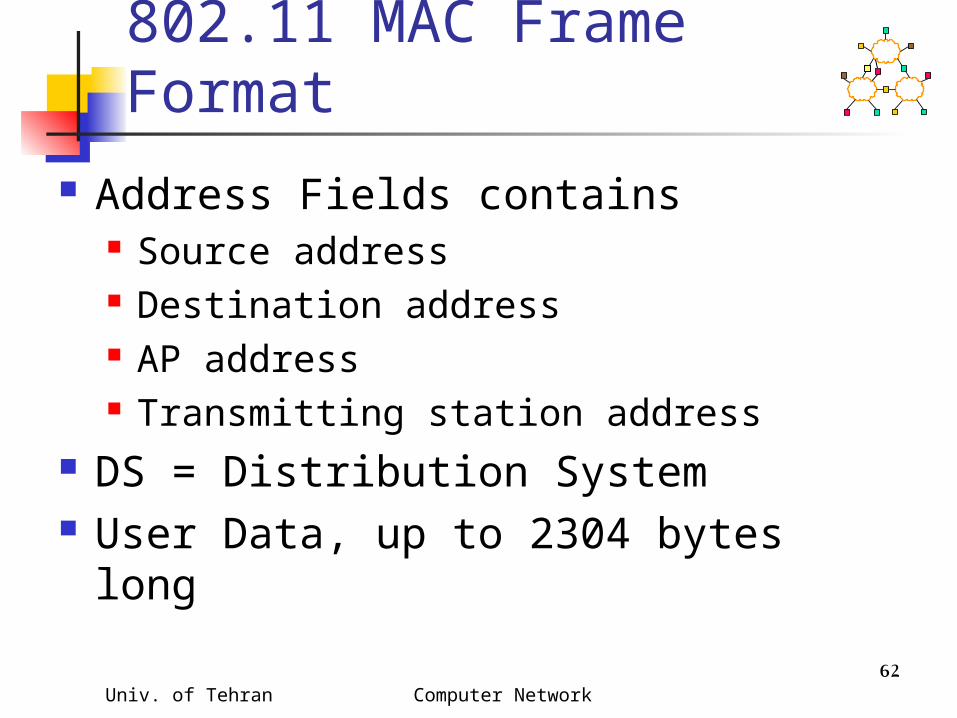
802.11 MAC Frame Format
Address Fields contains Source address Destination address AP address Transmitting station address
DS = Distribution System User Data, up to 2304 bytes long

Special Frames: ACK, RTS, CTS
Acknowledgement
Request To Send
Clear To Send
FrameControl
DurationReceiverAddress
TransmitterAddress
CRC
2 2 6 6 4bytes
FrameControl
DurationReceiverAddress
CRC
2 2 6 4bytes
FrameControl
DurationReceiverAddress
CRC
2 2 6 4bytes
ACK
RTS
CTS

Univ. of Tehran Computer Network 64
IEEE 802.11 LLC Layer Provides three type of service for
exchanging data between (mobile) devices connected to the same LAN Acknowledged connectionless Un-acknowledged connectionless,
useful for broadcasting or multicasting. Connection oriented
Higher layers expect error free transmission

Univ. of Tehran Computer Network 65
IEEE 802.11 LLC Layer, Cont..
Each SAP (Service Access Point) address is 7 bits. One bit is added to it to indicate whether it is order or response.
Control has three values Information, carry user data Supervisory, for error control and flow
control Unnumbered, other type of control packet
Destination SAP
Source SAP
DataControl
Univ. of Tehran Computer Network 66
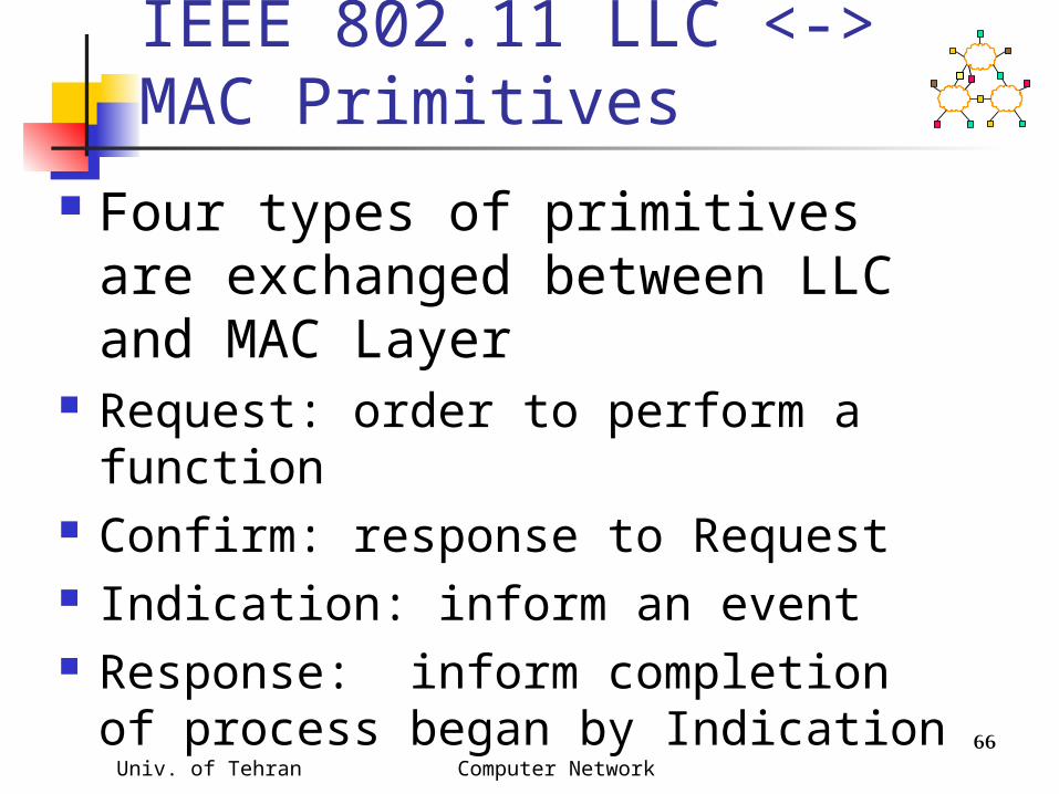
IEEE 802.11 LLC <-> MAC Primitives
Four types of primitives are exchanged between LLC and MAC Layer
Request: order to perform a function
Confirm: response to Request Indication: inform an event Response: inform completion of
process began by Indication
Univ. of Tehran Computer Network 67
Reception of packets AP Buffer traffic to sleeping nodes Sleeping nodes wake up to listen to
TIM (Traffic Indication Map) in the Beacon
AP send a DTIM (Delivery TIM) followed by the data for that station.
Beacon contains, time stamp, beacon interval, DTIM period, DTIM count, sync info, TIM broadcast indicator
Univ. of Tehran Computer Network 68
Frame type and subtypes Three type of frames
Management Control Asynchronous data
Each type has subtypes Control
RTS CTS ACK

Univ. of Tehran Computer Network 69
Frame type and subtypes, Cont..
Management Association request/ response Re-association request/ response:
transfer from AP to another. Probe request/ response privacy request/ response: encrypting
content Authentication: to establish identity Beacon (Time stamp, beacon interval,
channels sync info, etc.)

Univ. of Tehran Computer Network 70
Frame type and subtypes, Cont..
Management… TIM (Traffic Indication Map) indicates
traffic to a dozing node dissociation

Univ. of Tehran Computer Network 71
802.11 Management Operations
Scanning Association/Reassociation Time synchronization Power management

Univ. of Tehran Computer Network 72
Scanning in 802.11 Goal: find networks in the area Passive scanning
Not require transmission Move to each channel, and listen for
Beacon frames Active scanning
Require transmission Move to each channel, and send Probe
Request frames to solicit Probe Responses from a network
Univ. of Tehran Computer Network 73
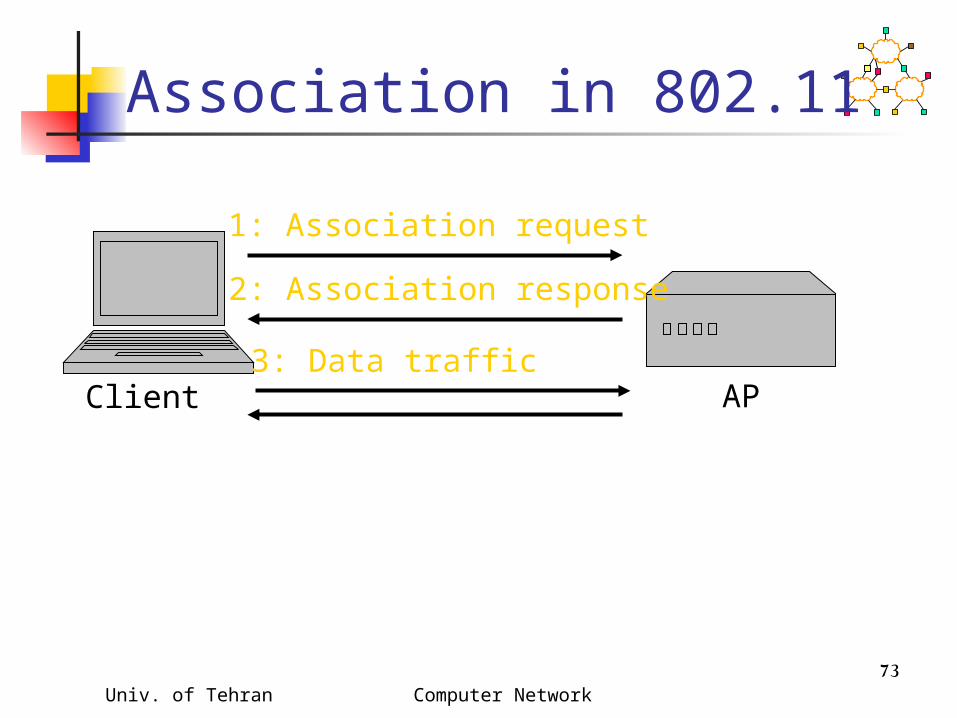
Association in 802.11
AP
1: Association request
2: Association response
3: Data trafficClient

Univ. of Tehran Computer Network 74
Reassociation in 802.11
New AP
1: Reassociation request
3: Reassociation response
5: Send buffered frames
Old AP
2: verifypreviousassociation
4: sendbufferedframes
Client6: Data traffic
Univ. of Tehran Computer Network 75
Time Synchronization in 802.11
Timing synchronization function (TSF) AP controls timing in infrastructure
networks All stations maintain a local timer TSF keeps timer from all stations in sync
Periodic Beacons convey timing Beacons are sent at well known intervals Timestamp from Beacons used to calibrate
local clocks Local TSF timer mitigates loss of Beacons

Univ. of Tehran Computer Network 76
Power Management in 802.11
A station is in one of the three states Transmitter on Receiver on Both transmitter and receiver off (dozing)
AP buffers packets for dozing stations AP announces which stations have frames
buffered in its Beacon frames Dozing stations wake up to listen to the
beacons If there is data buffered for it, it sends a poll
frame to get the buffered data

Univ. of Tehran Computer Network 77
Authentication Three levels of authentication
Open: AP does not challenge the identity of the node.
Password: upon association, the AP demands a password from the node.
Public Key: Each node has a public key. Upon association, the AP sends an encrypted message using the nodes public key. The node needs to respond correctly using it private key.

Univ. of Tehran Computer Network 78
Inter Frame Spacing SIFS = Short inter frame space =
dependent on PHY PIFS = point coordination function (PCF)
inter frame space = SIFS + slot time DIFS = distributed coordination
function (DCF) inter frame space = PIFS + slot time
The back-off timer is expressed in terms of number of time slots.

Univ. of Tehran Computer Network 79
802.11 Frame Priorities
Short interframe space (SIFS) For highest priority frames (e.g., RTS/CTS, ACK)
PCF interframe space (PIFS) Used by PCF during contention free operation
DCF interframe space (DIFS) Minimum medium idle time for contention-based
services
Time
Busy SIFSPIFS
DIFS
contentwindow
Frame transmission

Univ. of Tehran Computer Network 80
SIFS/DIFSSIFS makes RTS/CTS/Data/ACK atomicExample: Slot Time = 1, CW = 5, DIFS=3,
PIFS=2, SIFS=1,

Univ. of Tehran Computer Network 81
Priorities in 802.11 CTS and ACK have priority over RTSAfter channel becomes idle If a node wants to send CTS/ACK, it
transmits SIFS duration after channel goes idle
If a node wants to send RTS, it waits for DIFS > SIFS
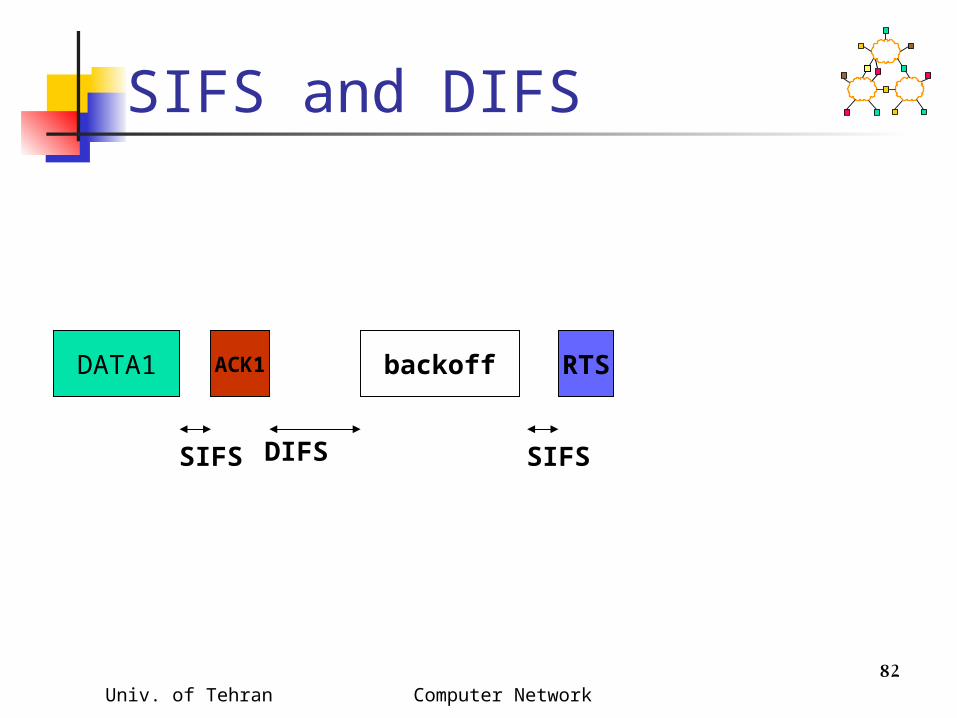
Univ. of Tehran Computer Network 82
SIFS and DIFS
DATA1 ACK1
SIFS
backoff
DIFS
RTS
SIFS

Univ. of Tehran Computer Network 83
Energy Conservation Since many mobile hosts are
operated by batteries, MAC protocols which conserve energy are of interest
Two approaches to reduce energy consumption Power save: Turn off wireless interface
when desirable Power control: Reduce transmit power

Univ. of Tehran Computer Network 84
Power Control with 802.11 Transmit RTS/CTS/DATA/ACK at
least power level needed to communicate with the receiver
A/B do not receive RTS/CTS from C/D. Also do not sense D’s data transmission
B’s transmission to A at high power interferes with reception of ACK at C
B C DA
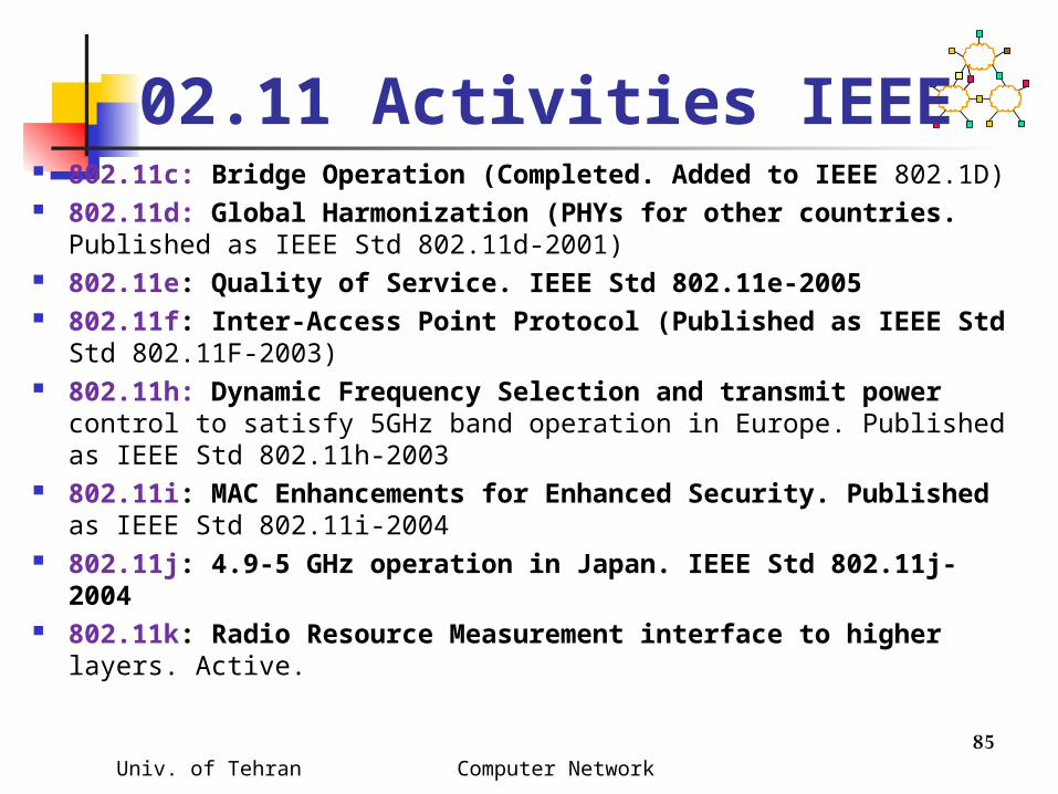
02.11 Activities IEEE 802.11c: Bridge Operation (Completed. Added to IEEE 802.1D) 802.11d: Global Harmonization (PHYs for other countries.
Published as IEEE Std 802.11d-2001) 802.11e: Quality of Service. IEEE Std 802.11e-2005 802.11f: Inter-Access Point Protocol (Published as IEEE Std
Std 802.11F-2003) 802.11h: Dynamic Frequency Selection and transmit power
control to satisfy 5GHz band operation in Europe. Published as IEEE Std 802.11h-2003
802.11i: MAC Enhancements for Enhanced Security. Published as IEEE Std 802.11i-2004
802.11j: 4.9-5 GHz operation in Japan. IEEE Std 802.11j-2004 802.11k: Radio Resource Measurement interface to higher
layers. Active.
Univ. of Tehran Computer Network 85

02.11 Activities IEEE 802.11m: Maintenance. Correct editorial and technical issues
in 802.11a/b/d/g/h. Active. 802.11n: Enhancements for higher throughput (100+ Mbps).
Active. 802.11p: Inter-vehicle and vehicle-road side communication
at 5.8GHz. Active. 802.11r: Fast Roaming. Started July 2003. Active. 802.11s: ESS Mesh Networks. Active. 802.11T: Wireless Performance Metrics. Active. 802.11u: Inter-working with External Networks. Active. 802.11v: Wireless Network Management enhancements for
interface to upper layers. Extension to 80211.k. Active. Study Group ADS: Management frame security. Active Standing Committee Wireless Next Generation WNG:
Globalization jointly w ETSI-BRAN and MMAC. Active.
Univ. of Tehran Computer Network 86

Univ. of Tehran Computer Network 87
IEEE 802.11 Wireless MAC Distributed and centralized MAC
components Distributed Coordination Function (DCF) Point Coordination Function (PCF)
DCF suitable for multi-hop and ad hoc networking
DCF is a Carrier Sense Multiple Access/Collision Avoidance (CSMA/CA) protocol

Univ. of Tehran Computer Network 88
IEEE 802.11 DCF Uses RTS-CTS exchange to avoid hidden
terminal problem Any node overhearing a CTS cannot transmit for
the duration of the transfer Uses ACK to achieve reliability Any node receiving the RTS cannot transmit
for the duration of the transfer To prevent collision with ACK when it arrives at the
sender When B is sending data to C, node A will keep
quiteA B C

Univ. of Tehran Computer Network 89
A B C
Hidden Terminal Problem
Node B can communicate with A and C both
A and C cannot hear each other When A transmits to B, C cannot
detect the transmission using the carrier sense mechanism
If C transmits, collision will occur at node B
Univ. of Tehran Computer Network 90
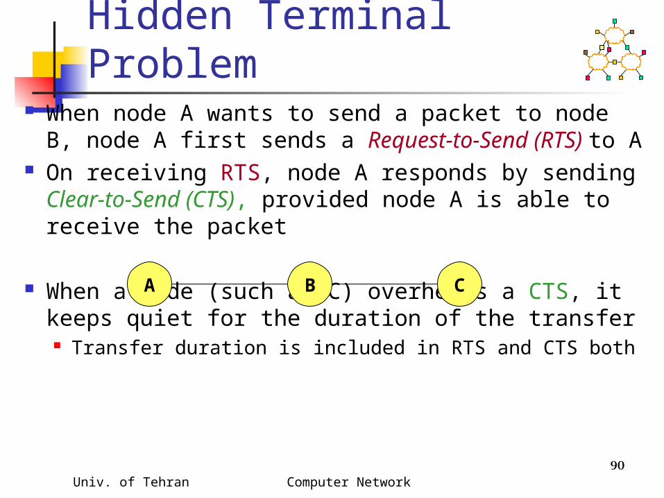
MACA Solution for Hidden Terminal Problem
When node A wants to send a packet to node B, node A first sends a Request-to-Send (RTS) to A
On receiving RTS, node A responds by sending Clear-to-Send (CTS), provided node A is able to receive the packet
When a node (such as C) overhears a CTS, it keeps quiet for the duration of the transfer Transfer duration is included in RTS and CTS both
A B C

Univ. of Tehran Computer Network 91
IEEE 802.11
C FA B EDRTS
RTS = Request-to-Send

Univ. of Tehran Computer Network 92
IEEE 802.11
C FA B EDRTS
RTS = Request-to-Send
NAV = 10
NAV = remaining duration to keep quiet
Univ. of Tehran Computer Network 93
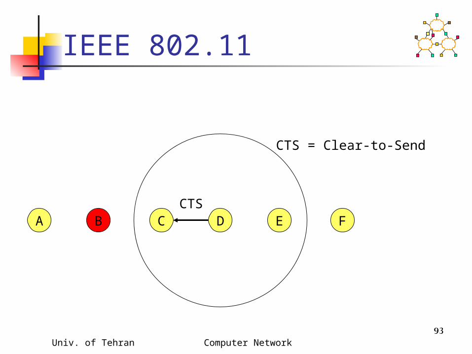
IEEE 802.11
C FA B EDCTS
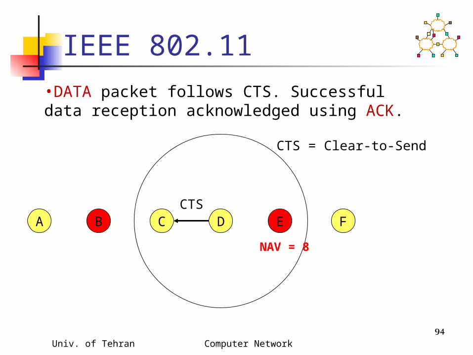
CTS = Clear-to-Send
Univ. of Tehran Computer Network 94
IEEE 802.11
C FA B EDCTS
CTS = Clear-to-Send
NAV = 8
•DATA packet follows CTS. Successful data reception acknowledged using ACK.

Univ. of Tehran Computer Network 95
IEEE 802.11
C FA B EDDATA

Univ. of Tehran Computer Network 96
C FA B EDACK
IEEE 802.11
Reserved area

Univ. of Tehran Computer Network 97
IEEE 802.11
C FA B EDDATA
Transmit range
Interferencerange
Carrier senserange
FA

Univ. of Tehran Computer Network 98
IEEE 802.11
C FA B EDACK
Univ. of Tehran Computer Network 99
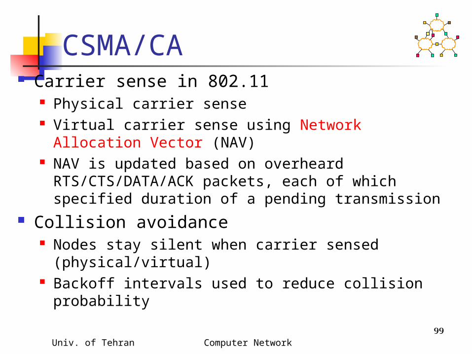
CSMA/CA Carrier sense in 802.11
Physical carrier sense Virtual carrier sense using Network Allocation Vector
(NAV) NAV is updated based on overheard
RTS/CTS/DATA/ACK packets, each of which specified duration of a pending transmission
Collision avoidance Nodes stay silent when carrier sensed
(physical/virtual) Backoff intervals used to reduce collision probability
Univ. of Tehran Computer Network 100
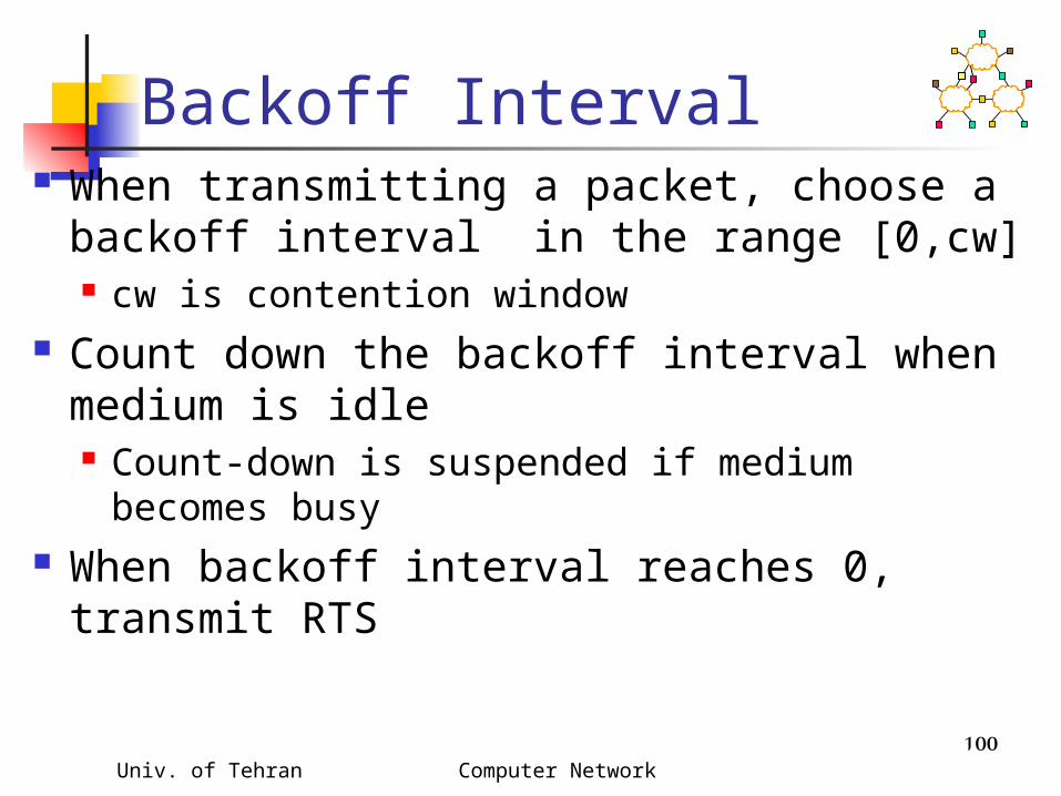
Backoff Interval When transmitting a packet, choose a
backoff interval in the range [0,cw] cw is contention window
Count down the backoff interval when medium is idle Count-down is suspended if medium
becomes busy When backoff interval reaches 0,
transmit RTS

Univ. of Tehran Computer Network 101
DCF Example
data
waitB1 = 5
B2 = 15
B1 = 25
B2 = 20
data
wait
B1 and B2 are backoff intervalsat nodes 1 and 2cw = 31
B2 = 10
Univ. of Tehran Computer Network 102
Backoff Interval
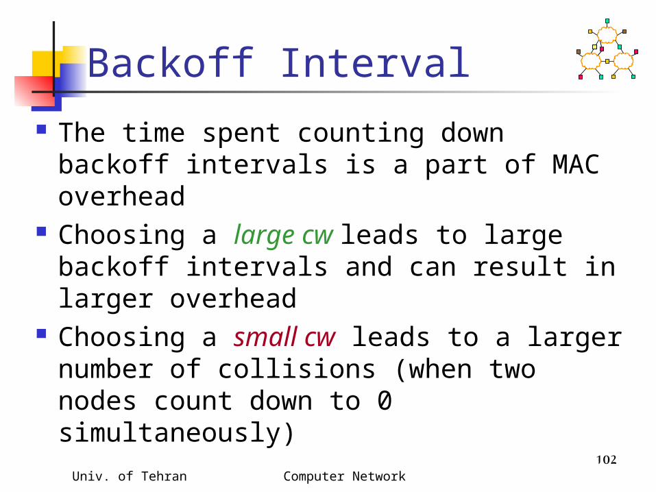
The time spent counting down backoff intervals is a part of MAC overhead
Choosing a large cw leads to large backoff intervals and can result in larger overhead
Choosing a small cw leads to a larger number of collisions (when two nodes count down to 0 simultaneously)

Univ. of Tehran Computer Network 103
Binary Exponential Backoff in DCF
When a node fails to receive CTS in response to its RTS, it increases the contention window cw is doubled (up to an upper bound)
When a node successfully completes a data transfer, it restores cw to Cwmin cw follows a sawtooth curve
802.11 has large room for improvement
Random backoff
Data Transmission/ACKRTS/CTS

Univ. of Tehran Computer Network 104
Related Standards Activities
IEEE 802.11 http://grouper.ieee.org/groups/802/11/
Hiperlan/2 http://www.etsi.org/technicalactiv/hiperlan2.htm
BlueTooth http://www.bluetooth.com
IETF manet (Mobile Ad-hoc Networks) working group http://www.ietf.org/html.charters/manet-charter.h
tml