Embed Size (px)
Citation preview

1
CISCO NETWORKING ACADEMY PROGRAM (CNAP)SEMESTER 1/ MODULE 8
Ethernet Switching

2
CISCO NETWORKING ACADEMY PROGRAMSEMESTER 1/ MODULE 6
Ethernet Fundamentals
Objectives
• Upon completion of this module, students will be able to perform tasks related to the following:
• Ethernet Switching
• Collision Domains and Broadcast Domains

3
CISCO NETWORKING ACADEMY PROGRAMSEMESTER 1/ MODULE 8
Ethernet Switching
Layer 2 Bridging
• Bridge keeps a table of MAC addresses and the associated ports
• The bridge then forwards or discards frames based on the table entries

4
CISCO NETWORKING ACADEMY PROGRAMSEMESTER 1/ MODULE 8
Ethernet Switching
Layer 2 Switching
• Bridge will divide a collision domain but has no effect on a logical or broadcast domain • A switch is essentially a fast, multi-port bridge, which can contain dozens of ports• Rather than creating two collision domains, each port creates its own collision domain • A switch dynamically
builds and maintains a Content-Addressable Memory (CAM) table, holding all of the necessary MAC information for each port

5
CISCO NETWORKING ACADEMY PROGRAMSEMESTER 1/ MODULE 8
Ethernet Switching
Switch Operation
• When only one node is connected to a switch port, the collision domain or segment on the shared media contains only two nodes (switch port and host)
• These small physical segments are called microsegments• Switches are capable of supporting full duplex (capability of communication in
both directions at once)• For faster microprocessors and memory, two other technologies made switches
possible: • Content-addressable memory (CAM) is memory that allows a switch to
directly find the port that is associated with a MAC address without using search algorithms
• An application-specific integrated circuit (ASIC) is a device consisting of logic gates, operations can be done in hardware using an ASIC, reduced the delays caused by software processing

6
CISCO NETWORKING ACADEMY PROGRAMSEMESTER 1/ MODULE 8
Ethernet Switching
Switch Operation

7
CISCO NETWORKING ACADEMY PROGRAMSEMESTER 1/ MODULE 8
Ethernet Switching
Full Duplex

8
CISCO NETWORKING ACADEMY PROGRAMSEMESTER 1/ MODULE 8
Ethernet Switching
Latency
• Latency is the delay between the time a frame first starts to leave the source device and the time the first part of the frame reaches its destination
• Latency may caused by:• Media delays caused by the
finite speed of the physical media
• Circuit delays caused by the electronics that process the signal along the path
• Software delays caused by the decisions that software must make to implement switching and protocols
• Delays caused by the content of the frame and where in the frame switching decisions can be made

9
CISCO NETWORKING ACADEMY PROGRAMSEMESTER 1/ MODULE 8
Ethernet Switching
Switch Modes
• There are 3 switch modes:
• Store and forward - switch receive the entire frame before sending it out the destination port, Frame Check Sum (FCS) is done to ensure that the frame was reliably received
• Cut-through - can start to transfer the frame as soon as the destination MAC address is received, no error checking is available
• Fragment-free - reads the first 64 bytes, which includes the frame header, and switching begins before the entire data field and checksum are read
• Store-and-forward mode must be used for asynchronous switching and cut-through must be used in synchronous switching
• Asymmetric switching provides switched connections between ports of unlike bandwidths, such as a combination of 100 Mbps and 1000 Mbps
• Symmetric switching provides each port with same bandwidth

10
CISCO NETWORKING ACADEMY PROGRAMSEMESTER 1/ MODULE 8
Ethernet Switching
Spanning Tree Protocol
• Switched networks are often designed with redundant paths which may leads to switching loop

11
CISCO NETWORKING ACADEMY PROGRAMSEMESTER 1/ MODULE 8
Ethernet Switching
Spanning Tree Protocol
• Spanning-Tree Protocol (STP) is used to solve switching loop by:• Sending Protocol Data Units (BPDUs) out all its ports to let other switches know of
its existence and to elect a root bridge for the network.• Switches then use the Spanning-Tree Algorithm (STA) to resolve and shut down the
redundant paths• A port moves through these five states as follows:
• From initialization to blocking • From blocking to listening or to disabled • From listening to learning or to disabled • From learning to forwarding or to disabled • From forwarding to disabled

12
CISCO NETWORKING ACADEMY PROGRAMSEMESTER 1/ MODULE 8
Ethernet Switching
Types of Networks

13
CISCO NETWORKING ACADEMY PROGRAMSEMESTER 1/ MODULE 8
Ethernet Switching
Collision Domain
• Collision domains are the connected physical network segments where collisions can occur
• The types of devices that interconnect the media segments define collision domains:• Layer 1 devices do not break up collision domains• Layer 2 and Layer 3 devices do break up collision domains
• Increasing the number of collision domains with Layer 2 and 3 devices is also known as segmentation
14
CISCO NETWORKING ACADEMY PROGRAMSEMESTER 1/ MODULE 8
Ethernet Switching
Collision Domain
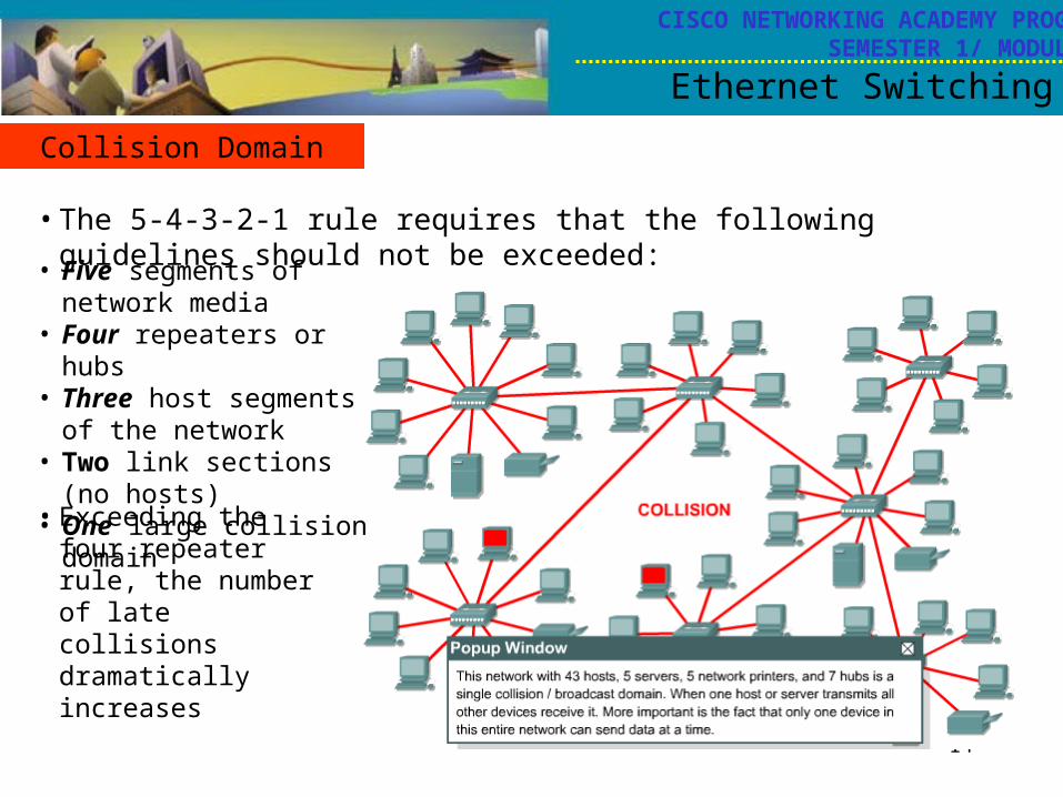
• The 5-4-3-2-1 rule requires that the following guidelines should not be exceeded:
• Five segments of network media
• Four repeaters or hubs • Three host segments of the
network • Two link sections (no hosts) • One large collision domain
• Exceeding the four repeater rule, the number of late collisions dramatically increases

15
CISCO NETWORKING ACADEMY PROGRAMSEMESTER 1/ MODULE 8
Ethernet Switching
Segmentation
• Layer 2 devices segment or divide collision domains by using MAC addresses to make forwarding decision
• By using bridges and switches, the collision domain is broken up into smaller parts, each becoming its own collision domain.
• Layer 3 devices, like Layer 2 devices, do not forward collisions.

16
CISCO NETWORKING ACADEMY PROGRAMSEMESTER 1/ MODULE 8
Ethernet Switching
Layer 2 Broadcasts
• To communicate with all collision domains, protocols use broadcast and multicast frames at Layer 2 of the OSI model.
• When a node needs to communicate with all hosts on the network, it sends a broadcast frame with a destination MAC address 0xFFFFFFFFFFFF like Address Resolution Protocol (ARP)
• Source of broadcasting are workstations, routers and multicast applications
• The circulation of broadcast radiation can saturate the network so that there is no bandwidth left for application data, this situation known as a broadcast storm

17
CISCO NETWORKING ACADEMY PROGRAMSEMESTER 1/ MODULE 8
Ethernet Switching
Broadcast Domains
• A broadcast domain is a grouping of collision domains that are connected by Layer 2 devices
• Broadcast domains are controlled or segmented at Layer 3 because routers do not forward broadcasts
• Because routers forward packet based on IP address, not MAC address

18
CISCO NETWORKING ACADEMY PROGRAMSEMESTER 1/ MODULE 8
Ethernet Switching
Introduction to Data Flow
• Layer 1 devices do no filtering, so everything that is received is passed on to the next segment
• Layer 2 devices filter data frames based on the destination MAC address
• Layer 3 devices filter data packets based on IP destination address

19
CISCO NETWORKING ACADEMY PROGRAMSEMESTER 1/ MODULE 8
Ethernet Switching
What is network segment?

20
CISCO NETWORKING ACADEMY PROGRAMSEMESTER 1/ MODULE 8
Ethernet Switching
Summary