Embed Size (px)
Citation preview

1
Chapter 1Chapter 1
Basic Pipelining and Simple RISC Basic Pipelining and Simple RISC ProcessorsProcessors

2
Basic Basic ppipelining and ipelining and ssimple RISC imple RISC pprocessorsrocessors
CISC: State-of-the-art computers in 1970s, e.g. IBM System/370 or VAX-11/780 were rack-based machines implemented with discrete logic.
VAX-11/780: complex instruction set, microcode, consisting of 304 instructions, 16 addressing modes, and more than 10 different instruction lengths.
Reasons: – Hardware technology of the pre 80ies required minimal hardware and minimal
memory size.– Assembly language programming required high-level constructs at assembly
language level.– Idea of a semantic gap between computer architecture and HLL programs.
Conclusions: – CISC (complex instruction set computer) ISA (instruction set architecture)– HLL (high-level language) machines

3
Instruction Average (% total executions)
load 22conditional branch 20compare 16store 12add 8and 6sub 5move register-register 4call 1return 1Total 95
The ten most frequently used instructions in the The ten most frequently used instructions in the SPECint92 for Intel x86SPECint92 for Intel x86

4
RISC RISC mmovement in ovement in pprocessor rocessor aarchitecturerchitecture
RISC = reduced instruction set computer Technological prerequisite (end of 70ies): VLSI chips of limited capacity make
very simple pipelined single-chip processor implementations feasible About 80% of the computations of a typical program required only about 20% of
the instructions in a processor's instruction set. The most frequently used instructions were simple instructions such as load,
store and add. Cooperation between a well-chosen set of simple instructions implemented
directly in hardware and an optimizing compiler. Having a small number of instructions can be traced back to 1964, when the
Control Data Corporation CDC 6600 used a small (64 opcodes) load/store and register-register instruction set,
mid 1970s, when researchers at IBM developed the IBM 801 End of 70ies: Patterson’s team at University of California at Berkeley (RISC I)
and Hennessy's team of Stanford University (MIPS) survey RISC processors.

5
Instruction Set Architecture (ISA)Instruction Set Architecture (ISA)
The programmers view of the machine depends on the answers to the following five questions:
– How is data represented?– Where can data be stored?– How can data be accessed?– What operations can be done on data?– How are instructions encoded?
The answers to these questions define
the Instruction Set Architecture (ISA) of the machine.

6
ISA - Processor ISA - Processor aarchitecture - Microarchitecturerchitecture - Microarchitecture
The instruction set architecture ISA refers to the programmer visible instruction set.– It defines the boundary between hardware and software.
Often the ISA is identified with the processor architecture. The processor microarchitecture refers to the internal organization of the
processor.– So, several specific processors with differing microarchitectures may
share the same architecture, i.e. the same ISA.
7
How is data represented?How is data represented? - Data formats- Data formats
The ISA supports several data formats by providing representations for integers, characters, floating-point, multimedia, etc.
Integer data formats can be signed or unsigned (e.g., in DEC Alpha there is byte, 16-bit word, 32-bit longword, and 64-bit quadword).
There are two ways of ordering byte addresses within a word– big-endian: most significant byte first, and – little-endian: least significant byte first.
There are also packed and unpacked BCD numbers, and ASCII characters. Floating-point data formats (ANSI/IEEE 754-1985):
standard, basic or extended, each having two widths: single or double. Multimedia data formats are 32-, 64-, and 128-bit words (soon perhaps also 256-
bit) concluding several 8- or 16-bit pixel representations or 32-bit (single precision) floating-point numbers used for 3D graphics.
8
Where can data be stored?Where can data be stored? - Address space- Address space
Several address spaces are distinguished by the (assembly language) programmer, such as register space, stack space, heap space, text space, I/O space, and control space.
Except for the registers, all other address spaces are mapped onto a single contiguous memory address space.
A RISC ISA additionally contains a register file, which consists of a relatively large number of general-purpose CPU registers- early RISC processors: MIPS: 32 32-bit general purpose registers,RISC I: register windowing
Contemporary RISC processors: additionally 32 64-bit floating-point and multimedia registers.

9
How can data be accessed?How can data be accessed? - Addressing modes- Addressing modes
Register mode: the operand is stored in one of the registers. Immediate (or literal) mode: the operand is a part of the instruction. Direct (or absolute) mode: the address of the operand in memory is stored in
the instruction. Register indirect (or register deferred) mode: the address of the operand in
memory is stored in one of the registers. Autoincrement (or register indirect with postincrement) mode: like the register
indirect, except that the content of the register is incremented after the use of the address. – This mode offers automatic address increment useful in loops and in
accessing byte, half-word, or word arrays of operands. Autodecrement (register indirect with predecrement) mode: the content of the
register is decremented and is then used as a register indirect address. – This mode can be used to scan an array in the direction of decreasing
indices.

10
Addressing Addressing mmodes (continued)odes (continued) Displacement (also register indirect with displacement or based) mode:
the effective address of the operand is the sum of the contents of a register and a value, called displacement, specified in the instruction.
Indexed and scaled indexed mode: works essentially as the register indirect. – The register containing the address is called index register. – The main difference between the register indirect and the indexed is that
the contents of the index register can be scaled by a scale factor (e.g. 1, 2, 4, 8 or 16).
– The availability of the scale factor, along with the index register, permits scanning of data structures of any size, at any desired step.
Indirect scaled indexed mode: the effective address is the sum of the contents of the register and the scaled contents of the index register.
Indirect scaled indexed with displacement mode: essentially as the indirect scaled indexed, except that a displacement is added to form the effective address.
PC-relative mode: a displacement is added to the PC. – The PC-relative mode is often used with branches and jumps.

11
Addressing Addressing mmodesodes
Addressing mode Example instruction / Meaning
Register load Reg1,Reg2 Reg1 ¬ (Reg2)
Immediate load Reg1,#const Reg1 ¬ const
Direct load Reg1,(const) Reg1 ¬ Mem[const]
Register load Reg1,(Reg2) indirect Reg1 ¬ Mem[(Reg2)]
Autoincrement load Reg1,(Reg2)+ Reg1 ¬ Mem[(Reg2)], Reg2 ¬ (Reg2) + step
Autodecrement load Reg1,-(Reg2) Reg2 ¬ (Reg2) - step, Reg1 ¬ Mem[(Reg2)]
Displacement load Reg1,displ(Reg2) Reg1 ¬ Mem[displ + (Reg2)]
Indexed and load Reg1,(Reg2*scale) scaled indexed Reg1 ¬ Mem[(Reg2)*scale]
Indirect load Reg1,(Reg2,Reg3*scale) scaled indexed Reg1 ¬ Mem[(Reg2) + (Reg3)*scale]
Indirect scaled indexed load Reg1,displ(Reg2,Reg3*scale) with displacement Reg1 ¬ Mem[displ + (Reg2) + (Reg3)*scale]
PC-relative branch displ PC ¬ PC + step + displ (if branch taken)
const,displ ... decimal, hexadecimal, octal or binary numbers
step ... e.g., 4 in systems with 4-byte uniform instruction size
scale ... scaling factor, e.g., 1, 2, 4, 8, 16

12
RISC RISC aaddressing ddressing mmodesodes
RISC ISAs have a small number of addressing modes, usually not exceeding four.
Displacement mode already includes: – the direct mode (by setting the register content to zero), – and the register indirect mode (by setting the displacement to zero).
13
What operations can be done on data?What operations can be done on data?- Instruction set- Instruction set Data movement instructions: transfer data from one location to another.
– When there is a separate I/O address space, these instructions also include special I/O instructions.
– Stack manipulation instructions (e.g. push, pop) also fall into this category. Integer arithmetic and logical instructions: can be one-operand (e.g.
complement), two-operand or three-operand instructions.– In some processors, different instructions are used for different data
formats of their operands. There may be separate signed and unsigned multiply/divide instructions.
Shift and rotate instructions: left or right shifts and rotations. – There are two types of shifts: logical and arithmetic.
Bit manipulation instructions: operate on specified fields of bits. The field is specified by its width and offset from the beginning of the word. Instructions usually include test (affecting certain flags), set, clear, and possibly others.

14
Instruction Instruction sset (continued)et (continued)
Multimedia instructions: – Process multiple sets of
small operands and obtain multiple results by a single instruction
– Utilization of subword parallelism (data parallel instructions, SIMD)
– Saturation arithmetic– Additional arithmetic,
masking and selection, reordering and conversion instructions

15
Instruction Instruction sset (continued)et (continued) Floating-point instructions: floating-point data movement, arithmetic,
comparison, square root, absolute value, transcendental functions, and others. Control transfer instructions: consist primarily of jumps, branches, procedure
calls, and procedure returns. We assume that jumps are unconditional and branches are conditional. Some systems may also have return from exception instructions.
System control instructions: allow the user to influence directly the operation of the processor and other parts of the computer system.
Special function unit instructions: perform particular operations on special function units (e.g. graphic units).Another type of special instructions are atomic instructions for controlling the access to critical sections in multiprocessors.
Depending on the way of specifying its operands an instruction can be one of the following types: – register-register, memory-register, register-memory, or memory-memory.
16
RISC ISARISC ISA
In a RISC ISA, all operations, except load and store are register-register instructions (an ISA of this type is called a load/store ISA).
Similarly to addressing modes, also the number of instructions is reduced in RISC ISA (e.g. up to 128).

17
How are instructions encoded? How are instructions encoded? - Instruction and addressing formats- Instruction and addressing formats
– 3-address instruction format: opcode | Dest | Src1 | Scr2; typically used by register-register (also called load/store) machines.
– 2-address instruction format: opcode | Dest/Src1 | Src2 ; often supported register-memory machines.
– 1-address instruction format: opcode | Src;supported by the accumulator machine.
– 0-address instruction format: only opcode;supported by the stack machine.
Most RISC ISAs use a 3-address instruction format where all instructions have a fixed length of 32 bits.
CISC ISAs often use register-memory with variable instruction lengths. Accumulator machines are today mostly found in microcontrollers. Also stack machines use variable instruction lengths, today exemplified in
JAVA processors.

18
Register-Register Register-Memory Accumulator Stack
load Reg1,A load Reg1,A load A push B load Reg2,B add Reg1,B add B push Aadd Reg3,Reg1,Reg2 store C,Reg1 store C add store C,Reg3 load Reg1,C load C pop C load Reg1,C sub Reg1,B sub B push B load Reg2,B store D,Reg1 store D push C sub Reg3,Reg1,Reg2 sub store D,Reg3 pop D
Machine
C = A + B
D = C - B
coded in four classes of ISA instruction formats:
ExamplesExamples

19
Examples of Examples of RISC ISAs:RISC ISAs:MIPS IIMIPS II
Data byte, 16-bit halfword, 32-bit word, 64-bit doubleword formats big- or little-endian, ANSI/IEEE 754-1985
Integer (CPU) registers (64- or 32-bit): 32 registers r0 to r31, program counter PC, two multiply and divide registers HI (remainder for divide) and LO (quotient for divide); r0 is Register hardwired to a zero, r31 is the link register for jumps and link instructions.file Floating-point (FPU) registers:
32 floating-point registers FGR0 to FGR31; can be configured as 16 64-bit registers; 32-bit implementation/revision register FCR0 with implementation and revision number of the FPU, 32-bit control/status register FCR31.
Addressing register, immediate, register indirect, displacement, modes PC-relative
Instruction load/store (24), computational (51), jump and branch (22), special (2),set (163) exception (16), floating point (30), coprocessor (9), memory management (9)
register-register, 3-address format Immediate (I-types):
6-bit opcode, 5-bit src register specifier, 5-bit dst register specifier or branch condition, 16-bit immediate value or branch displacement. Instruction Jump (J-types): formats 6-bit opcode, 26-bit jump target address. Register (R-type): 6-bit opcode, 5-bit src register specifier, 5-bit src register specifier, 5-bit dst register specifier, 5-bit shift amount, 6-bit function field

20
Examples of Examples of RISC ISAs:RISC ISAs:DEC AlphaDEC Alpha
Data byte, 16-bit word, 32-bit longword, 64-bit quadword formats little-endian, ANSI/IEEE 754-1985, VAX floating-point
Integer registers: 32 64-bit registers R0 to R31, program counter PC, R30 is designated as a stack pointer (SP), Register R31 is always equal to zero (hardwired to a zero value). file Floating-point registers: 32 64-bit floating-point registers F0 to F31, F31 is always equal to zero (hardwired to a zero value).
Addressing register, immediate, displacement, modes PC-relative
integer load/store (12), integer control (14), integer arithmetic (20), Instruction logical and shift (17), byte manipulation (24), set (155) floating-point load/store (8), floating-point control (6), floating-point operate (47), miscellaneous (7)
register-register, 3-address format Memory instructions:
6-bit opcode, 5-bit src register specifier, 5-bit src register specifier, 16-bit memory dst field, or function field (for miscellaneous instruction). Conditional branch instructions: 6-bit opcode, 5-bit branch condition, 21-bit branch displacement. Instruction Operate instructions: formats 6-bit opcode, 5-bit src register specifier, 5-bit src register specifier + 3-bit should be zero (if 12th bit is 0), or 8-bit literal (if 12th bit is 1), 7-bit function field, 5-bit dst register specifier. Floating-point operate instructions: 6-bit opcode, 5-bit src floating-point register specifier, 5-bit src floating-point specifier, 11-bit function field, 5-bit dst floating-point register destination. PALcode instructions: 6-bit opcode, 26-bit Privileged Architecture Library code.

21
Basic RISC Basic RISC ddesign esign pprinciplesrinciples
Hardwired control, no microcode Simple instructions and few addressing modes
– The ISA is designed so that most instructions remain only a single cycle in each pipeline stage:CPI (cycles per instruction) = IPC (Instructions per cycle) = 1
Register-register (or load/store) design Deep pipelining Reliance on optimizing compilers High-performance memory hierarchy

22
Datapath organization of a simple RISC processorDatapath organization of a simple RISC processor
Main Memory
PipelineDecode &Control ALU
D: Data Lines
PC: Program Counter
A: Address Lines
I-cache D-cache
DD AA
InstructionFetch
PC
MMUMMU
RegisterFile
Result Bus
Operand Bus B
Operand Bus A

23
Pipelining Pipelining ddefefinitioninitionss
Pipelining is an implementation technique whereby multiple instructions are overlapped in execution. It is not visible to the programmer!
Each step is called a pipe stage or pipe segment.
Pipeline machine cycle: time required to move an instruction one step down the pipeline.
Throughput of an pipeline: number of instructions that can leave the pipeline each cycle.
Latency is the time needed for an instruction to pass through all pipeline stages.

24
Speedup assumptionsSpeedup assumptions
n instructions execute in n*k cycles on a hypothetical non-pipelined processor with k stages,
the execution of n instructions on a k-stage pipeline will take k+n-1 cycles, assuming ideal conditions with latency k cycles and throughput 1.
Speedup = n*k / (k+n-1) = k / (k/n + 1 - 1/n)
Ideal speedup (n infinite) = k

25
The base pipeline is the most simple DLX RISC The base pipeline is the most simple DLX RISC pipelinepipeline
ID -- Instruction Decode/Register Fetch
EX -- Execute/Address CalculationIF
MEM -- Memory Access
ID
WB -- Write Back
EX MEM WB
IF -- Instruction Fetch
IF ID EX MEM WB
IF ID EX MEM WB
IF ID EX MEM WB
IF ID EX MEM WB
5-Deep
Current CPU Cycle
MasterClock Cycle

26
Basic Basic ppipeline ipeline sstepsteps Instruction fetch (IF): the instruction pointed to by the PC is fetched from
memory into the instruction register of the CPU, and the PC is incremented to point to the next instruction in the memory.
Instruction decode/register fetch (ID): the instruction is decoded, and in the second half of the stage the operands are transferred from the register file into the ALU input registers (here meaning: latches).
Execution/effective address calculation (EX): the ALU operates on the operands from ALU input registers and eventually puts the result into ALU output register. The contents of this register depend on the type of instruction. If the instruction is:– register-register (e.g. arithmetic/logical): the ALU outputs the result of the
operation into the ALU output register;– memory reference (e.g. load/store), the ALU output register contains an
effective memory address;– control transfer (e.g. branch on equal), then the ALU produces the jump /
branch target address (which is stored in the ALU output register) and, at the same time, the branch direction.

27
Basic Pipeline Steps (continued)Basic Pipeline Steps (continued) Memory access/branch completion (MEM): only for load, store, and branch
instructions. If the instruction is:– register-register: the content of the ALU output register is transferred to
the ALU result register. – load: the data is read from memory (as pointed to by the ALU output
register) and is placed in the load memory data register;– store: the data in the store value register is written into the D-cache (as
pointed to by the ALU output register);– control transfer: for jump and branch that is taken: the PC is replaced by
the ALU output register content; otherwise, the PC remains unchanged (in both cases, the next step WB is skipped);
Write back (WB): the result of the instruction execution (register-register or load instruction) is stored into the register file in the first half of the phase. In particular, the load memory data register or the ALU result register is written into the register file.

28
Pipeline (1)Pipeline (1)
I-cacheAdd
IF/IDRegisters
Inst
ruct
ion
fetc
h (I
F)
MUX
PC
PCInstructionRegister
4
132
32

29
Pipeline (2)Pipeline (2)
Register File
Register Addressing
ResultRegisterSelector
ID/EXRegisters
IF/ID Registers
Inst
ruct
ion
deco
de/
regi
ster
fet
ch (
ID)
PC
PC
ALU InputRegister 1
ALU InputRegister 2
ImmediateRegister
InstructionRegister
5 16 32
323232
55
SignExtended
Reg
iste
rs W
rite
Val
ue

30
Pipeline (3)Pipeline (3)
EX/MEMRegisters
ID/EXRegisters
Exe
cuti
on/e
ffec
tive
addr
ess
calc
ulat
ion
(EX
)
MUX MUX
ALU
PC ALU InputRegister 1
ALU InputRegister 2
ImmediateRegister
True/False
ConditionalRegister
32
ALU OutputRegister
1
Zero ?
Store ValueRegister
True/False

31
Pipeline (4)Pipeline (4)
D-cache
MUX
Wri
teba
ck (
WB
)
MEM/WBRegisters
EX/MEMRegisters
Mem
ory
acce
ss/b
ranc
hco
mpl
etio
n (M
EM
)
Load MemoryData Register
ALU ResultRegister
Store ValueRegister
ALU OutputRegister
True/False
ConditionalRegister
Load/StoreAddress
Jump/Branch Target Address AL
U R
esul
t Val
ue

32
Pipeline (Overview)Pipeline (Overview)
33
DiscussionDiscussion
The cycle time of the pipeline is dictated by the critical path: the slowest pipeline stage.
All stages use different CPU resources (no resource conflicts are possible in our simple but well-balanced pipeline!).
Ideally, each cycle another instruction is fetched, decoded, executed, etc. (CPI=1).
Pipeline hazards: phenomena that disrupt the smooth execution of a pipeline. Example:
– If we assume a unified cache with a single read port (instead of separate I- and D-caches) a memory read conflict appears among IF and MEM stages.
– The pipeline has to stall one of the accesses until the required memory port is available.
A stall is also called a pipeline bubble.

34
Pipelining Pipelining hhazards and azards and ssolutionsolutions- Three types of pipeline hazards- Three types of pipeline hazards Data hazards arise because of the unavailability of an operand
– For example, an instruction may require an operand that will be the result of a preceding, still uncompleted instruction.
Structural hazards may arise from some combinations of instructions that cannot be accommodated because of resource conflicts– For example, if processor has only one register file write port and two
instructions want to write in the register file at the same time. Control hazards arise from branch, jump, and other control flow instructions
– For example, a taken branch interrupts the flow of instructions into the pipeline the branch target must be fetched before the pipeline can resume execution.
Common solution is to stall the pipeline until the hazard is resolved, inserting one or more “bubbles” in the pipeline.

35
DependencesDependences
Assume: Inst1 is followed by Instr2.
Instr2 is (true) data dependent on Inst1, if Inst1 writes its output in a register Reg (or memory location) that Instr2 reads as its input.
Instr2 is antidependent Inst1 if Inst1 reads data from a register Reg (or memory location) which is subsequently overwritten by Instr2.
Instr2 is output dependent Inst1 if both write in the same register Reg (or memory location) and Instr2 writes its output after Inst1.
Instr2 control dependent Inst1 if Inst1 must complete before a decision can be made whether or not to execute Instr2.
A data dependence is sometimes also called true or real data dependence, while anti- and output dependences are sometimes called false or name dependences.

36
Data HazardsData Hazards
Dependences between instructions may cause data hazards when Instr1 and Instr2 are so close that their overlapping within the pipeline would change their access order to Reg.
Three types of data hazards:
Read After Write (RAW): Instr2 tries to read operand before Instr1 writes it.
Write After Read (WAR): Instr2 tries to write operand before Inst1 reads it.
Write After Write (WAW): Instr2 tries to write operand before Instr1 writes it.

37
IF ID EX MEM
load Reg1,A
load Reg2,B
add Reg2,Reg1,Reg2
mul Reg1,Reg2,Reg1
IF ID EX MEM
IF ID EX MEM
IF ID EX MEM WB
WB
WB
WB
timecycle time
Data hazards in an instruction pipelineData hazards in an instruction pipeline

38
WAR and WAW: can they happen in our pipeline?WAR and WAW: can they happen in our pipeline?
WAR and WAW can’t happen in DLX 5 stage pipeline because:– All instructions take 5 stages, – Register reads are always in stage 2, and – Register writes are always in stage 5.
WAR and WAW may happen in more complicated pipes.

39
add Reg2,Reg1,Reg2
mul Reg1,Reg2,Reg1
IF ID EX MEM
IF ID EX MEM WB
WB
timecycle time
Reg2 old Reg2 new
wrong register read!
Pipeline conflict due to a data hazardPipeline conflict due to a data hazard

40
Solutions for data hazards from true data Solutions for data hazards from true data dependencesdependences Software solution (Compiler scheduling):
– Putting no-op instructions after each instruction that may cause a hazard– Instruction scheduling: rearrange code to reduce no-ops
Hardware solutions: detect hazard!! Hazard detection logic necessary!– Interlocking: stall pipeline for one or more cycles– Forwarding: In our pipeline two types of forwarding:
• the result in ALU output of Instr1 in EX stage can immediately be forwarded back to ALU input of EX stage as an operand for Instr2,
• the load memory data register from MEM stage can be forwarded to ALU input of EX stage.
– Forwarding with interlocking: Assuming that Instr2 is data dependent on the load instruction Instr1 then Instr2 has to be stalled until the data loaded by Instr1 becomes available in the load memory data register in MEM stage. Even when forwarding is implemented from MEM back to EX, one bubble occurs that cannot be removed.

41
add Reg2,Reg1,Reg2
mul Reg1,Reg2,Reg1
IF ID EX MEM
IF ID EX MEM WB
WB
time
Register Reg2
bubbles
Data hazard: Hardware solution by interlockingData hazard: Hardware solution by interlocking
42
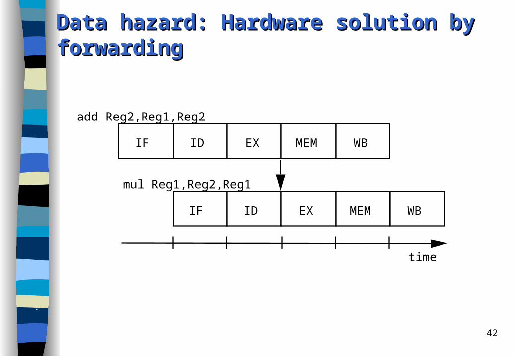
add Reg2,Reg1,Reg2
mul Reg1,Reg2,Reg1
IF ID EX MEM
IF ID EX MEM WB
WB
time
Data hazard: Hardware solution by forwardingData hazard: Hardware solution by forwarding

43
load Reg2,B
add Reg2,Reg1,Reg2
IF ID EX MEM
IF ID EX MEM
WB
WB
not possible!
timecycle time
Pipeline hazard due to data dependence Pipeline hazard due to data dependence unresolvable unresolvable by forwardingby forwarding

44
load Reg2,B
add Reg2,Reg1,Reg2
IF ID EX MEM
IF ID EX MEM
WB
WB
timebubble
Unremovable pipeline bubble due to data Unremovable pipeline bubble due to data dependencedependence

45
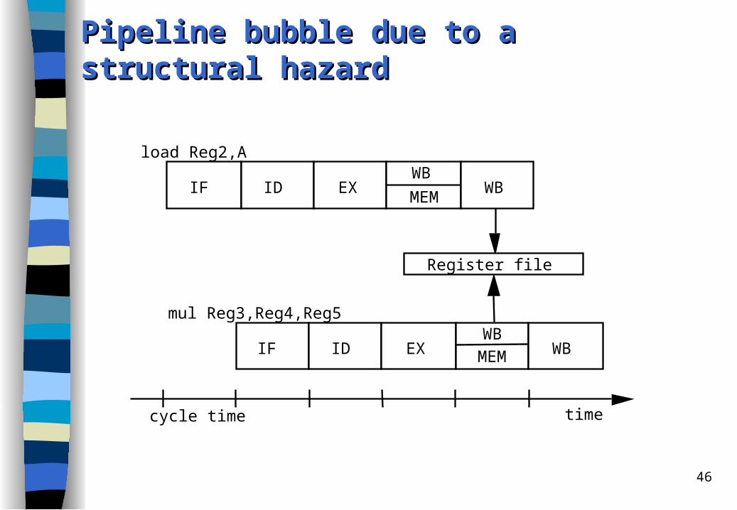
Structural HazardsStructural Hazards
Problem (resource conflict): Structural hazards do not arise in our simple pipeline.
However, assume: the pipeline would be able to write back results of register-register instructions already in MEM stage (and not in WB stage):– MEM stage would be able to write back an ALU output in case of a register-
register instruction (from ALU output register) into a single-write-port register file.
– Consider a sequence of two instructions, Instr1 and Instr2, with Instr1 fetched before Instr2, and assume that Instr1 is a load, while Instr2 is a data independent register-register instruction.
– Due to memory addressing, the data loaded by Instr1 arrives at the register file write port at the same time as the result of Instr2, causing a resource conflict.
46
load Reg2,A
mul Reg3,Reg4,Reg5
IF ID EXMEM
IF ID EX MEM WB
WB
timecycle time
Register file
WB
WB
Pipeline bubble due to a structural hazardPipeline bubble due to a structural hazard
47
Solutions to the structural hazardSolutions to the structural hazard
Arbitration with interlocking: hardware that performs resource conflict arbitration and interlocks one of the competing instructions
Resource replication: In the example a register file with multiple write ports would enable simultaneous writes.
– However, now output dependences may arise! – Therefore additional arbitration and interlocking necessary– or the first (in program flow) value is discarded and the second used.

48
Control Hazards, Control Hazards, ddelayed elayed bbranch ranch ttechnique,echnique,and and sstatic tatic bbranch ranch ppredictionrediction
Problem (control conflicts). Control hazards can be caused by jumps and by branches.
Assume Inst1 is a branch instruction.
The branch direction and the branch target address are both computed in EX stage (the branch target address replaces the PC in the MEM stage).
If the branch is taken, the correct instruction sequence can be started with a delay of three cycles since three instructions of the wrong branch path are already loaded in different stages of the pipeline.
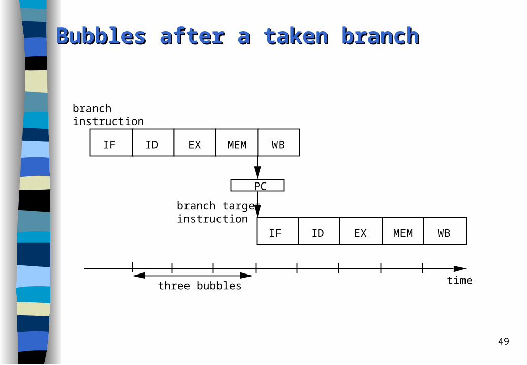
49
branchinstruction
branch targetinstruction
IF ID EX MEM
IF ID EX MEM WB
WB
time
PC
three bubbles
Bubbles after a taken branchBubbles after a taken branch

50
Solution: Decide branch direction earlierSolution: Decide branch direction earlier
Calculation of the branch direction and of the branch target address should be done in the pipeline as early as possible.
Best solution: Already in ID stage after the instruction has become recognized as branch instruction.

51
Solution: Calculation of the branch direction and of Solution: Calculation of the branch direction and of
the branch target address in ID stagethe branch target address in ID stage However, then the ALU can no more be used for calculating the branch target
address a structural hazard, which can be avoided by an additional ALU for the branch target address calculation in ID stage.
And a new unremovable pipeline hazard arises: – An ALU instruction followed by an (indirect) branch on the result of the
instruction will incur a data hazard stall even when the result value is forwarded from the EX to the ID stage (similar to the data hazard from a load with a succeeding ALU operation that needs the loaded value).
The main problem with this pipeline reorganization: decode, branch target address calculation, and PC write back within a single pipeline stage a critical path in the decode stage that reduces the cycle rate of the whole pipeline.
Assuming an additional ALU and a write back of the branch target address to the PC already in the ID stage, if the branch is taken, only a one cycle delay slot arises

52
Software SolutionSoftware Solution Delayed jump / branch technique: The compiler fills the delay slot(s) with
instructions that are in logical program order before the branch. – The moved instructions within the slots are executed regardless of the
branch outcome. – The probability of:
• moving one instruction into the delay slot is greater than 60%, • moving two instructions is 20%, • moving three instructions is less than 10%.
The delayed branching was a popular technique in the first generations of scalar RISC processors, e.g. IBM 801, MIPS, RISC I, SPARC.
In superscalar processors, the delayed branch technique complicates the instruction issue logic and the implementation of precise interrupts. However, due to compatibility reasons it is still often in the ISA of some of today's microprocessors, as e.g. SPARC- or MIPS-based processors.

53
Hardware solution Hardware solution - - InterlockingInterlocking
Interlocking: This is the simplest way to deal with control hazards: the hardware must detect the branch and apply hardware interlocking to stall the next instruction(s).
For our base pipeline this produces three bubbles in cases of jump or of (taken) branch instructions (since branch target address is written back to the PC during MEM stage).

54
Static branch predictionStatic branch prediction
The prediction direction for an individual branch remains always the same!– the machine cannot dynamically alter the branch prediction (in contrast to
dynamic branch prediction which is based on previous branch executions).
So static branch prediction comprises:– machine-fixed prediction (e.g. always predict taken) and – compiler-driven prediction.
If the prediction followed the wrong instruction path, then the wrongly fetched instructions must be squashed from the pipeline.

55
Static Static bbranch ranch pprediction - rediction - MMachine-fixedachine-fixed
Wired taken/not-taken prediction: The static branch prediction can be wired into the processor by predicting that all branches will be taken (or all not taken).
Direction based prediction: backward branches are predicted to be taken and forward branches are predicted to be not taken helps for loops.

56
Static Static bbranch ranch ppredictionrediction - - CCompiler-basedompiler-based
Opcode bit in branch instruction allows the compiler to reverse the hardware prediction.
There are two approaches the compiler can use to statically predict which way a branch will go: – it can examine the program code, – or it can use profile information (collected from earlier runs)

57
Hardware solutions: BTACHardware solutions: BTAC The BTAC is a set of tuples each of which contains:
– Field 1: the address of a branch (or jump) instruction (which was executed in the past),
– Field 2: the most recent target address for that branch or jump,– Field 3: information that permits a prediction as to whether or not the
branch will be taken. The BTAC functions as follows:
– The IF stage compares PC against the addresses of jump and branch instructions in BTAC (Field 1). ---- Suppose a match:
– If the instruction is a jump, then the target address is used as new PC. If the instruction is a branch, a prediction is made based on information from BTAC (Field 3) as to whether the branch is to be taken or not.If predict taken, the most recent branch target address is read from BTAC (Field 2) and used to fetch the target instruction.
– Of course, a misprediction may occur. Therefore, when the branch direction is actually known in the MEM stage, the BTAC can be updated with the corrected prediction information and the branch target address.

58
BTAC (continued)BTAC (continued)
To keep the size of BTAC small, only predicted taken branch addresses are stored.– Effective with static prediction!
If the hardware alters the prediction direction due to the history of the branch, this kind of branch prediction is called dynamic branch prediction. – Now the branch target address (of "taken") is stored also if the prediction
direction may be "not taken".– If the branch target address is removed for branches that are not taken
BTAC is better utilized.– However branch target address must be newly computed if the prediction
direction changes to "predict taken“.

59
BTB (Branch target buffer)BTB (Branch target buffer)
BTAC can be extended to implement branch folding: not only the branch target address is stored but also the target instruction itself and possibly a few of its successor instructions. Such a cache is called branch target cache (BTC) or branch target buffer (BTB).
The BTB may have two advantages:– The instruction is fetched from the BTB instead of memory more time can
be used for searching a match within the BTB; this allows a larger BTB.– When the target instruction of the jump (or branch) is in BTB, it is fed into the
ID stage of the pipeline replacing the jump (or branch) instruction itself.
60
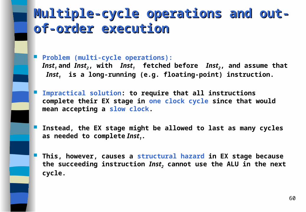
Multiple-cycle Multiple-cycle ooperations and perations and oout-of-order ut-of-order eexecutionxecution
Problem (multi-cycle operations): Inst1 and Inst2, with Inst1 fetched before Inst2, and assume that Inst1 is a long-running (e.g. floating-point) instruction.
Impractical solution: to require that all instructions complete their EX stage in one clock cycle since that would mean accepting a slow clock.
Instead, the EX stage might be allowed to last as many cycles as needed to complete Inst1.
This, however, causes a structural hazard in EX stage because the succeeding instruction Inst2 cannot use the ALU in the next cycle.

61
Example of a WAW Example of a WAW hhazard azard ccaused by a aused by a llong-ong-latency latency ooperation and peration and oout-of-order ut-of-order ccompletionompletion
div Reg3,Reg11,Reg12
mul Reg3,Reg1,Reg2
IF ID EX ...
IF ID EX MEM WB
EX
time
Register Reg3
MEM WB
several cycleslater

62
Solutions to the problem of multiple-cycle operations Interlocking: stall Inst2 in the pipeline until Inst1 leaves the EX stage
pipeline bubbles, slow down A single pipelined FU: general-purpose FU for all kind of instructions
slows down execution of simple operations Multiple FUs: Inst2 may proceed to some other FU and overlap its EX stage with
the EX stage of Inst1
out-of-order execution!– instructions complete out of the original program order– WAW hazard caused by output dependence may occur
delaying write back of second operation solves WAW hazard further solutions: scoreboarding, Tomasulo, reorder buffer in superscalar
Solutions in the example– delay mul instruction until div instruction has written its result– write back result of mul instruction and purge result of div
question: precise interrupt in case of division by zero ?

63
WAR possible?WAR possible?
WAR may occur if instruction can complete before a previous instruction reads its operand
extreme case of out-of-order execution
superscalar processors
not our simple RISC processor which ”issues” and starts execution in-order

64
Pipelining basics: summaryPipelining basics: summary Hazards limit performance
– Structural hazards: need more HW resources– Data hazards: need detection and forwarding– Control hazards: early evaluation, delayed branch, prediction
Compilers may reduce cost of data and control hazards– Compiler Scheduling– Branch delay slots– Static branch prediction
Increasing length of pipe increases impact of hazards; pipelining helps instruction bandwidth, not latency
Multi-cycle operations (floating-point) and interrupts make pipelining harder

65
RISC Processors: Early RISC Processors
Berkeley RISC I, II SPARC microSPARCII
Stanford MIPS MIPS R3000 MIPS R4000 and 4400
contrasted to: picoJava I (no RISC, stack architecture)

66
Case Case sstudy: MIPS R3000tudy: MIPS R3000
scalar RISC processor introduced in 1995
most similar to DLX
5-stage pipeline: IF, ID, EX, MEM, WB; cannot recognize pipeline hazards!
32-bit instructions with three formats
32 32-bit registers

67
Case Study: Case Study: MIPS R3000MIPS R3000
Exception/Control
Memory Management
48-entry TLB
Registers
Registers
System Control Coprocessor CP0
CPU Registers
ALU
Shifter
Integer Multiplier/Divider
Address Adder
PC Increment/MUX
Integer Unit CPU
Master Pipeline/Bus Control
Virtual Page Number/Virtual Address
Address(18)Tag(20+4) Data(32+4)
Control
LocalControlLogic

68
Case Study: MIPS R4000 (and R4400)Case Study: MIPS R4000 (and R4400)
8 Stage Pipeline (sometimes called: superpipeline):– IF: first half of fetching of instruction; PC selection, initiation of instruction
cache access.– IS: second half of access to instruction cache. – RF: instruction decode and register fetch, hazard checking, and also
instruction cache hit detection.– EX: execution, which includes effective address calculation, ALU
operation, and branch target computation and condition evaluation.– DF: data fetch, first half of access to data cache.– DS: second half of access to data cache.– TC: tag check, determine whether the data cache access hit.– WB: write back for loads and register-register operations.
More details in book!
69
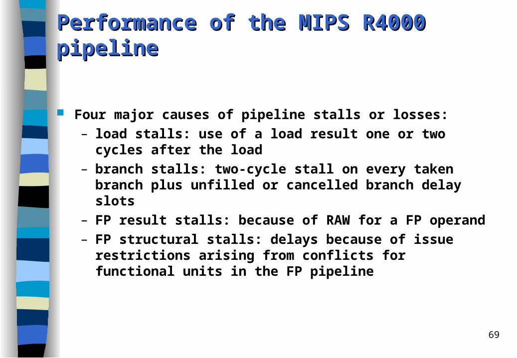
Performance of the MIPS R4000 Performance of the MIPS R4000 ppipelineipeline
Four major causes of pipeline stalls or losses:– load stalls: use of a load result one or two cycles after the load– branch stalls: two-cycle stall on every taken branch plus unfilled or
cancelled branch delay slots– FP result stalls: because of RAW for a FP operand– FP structural stalls: delays because of issue restrictions arising from
conflicts for functional units in the FP pipeline

70
Java-Java-pprocessors rocessors ooverviewverview
Java Virtual Machine and Java Byte Code
Java-processors picoJava-I and microJava 701
Evaluation with respect to embedded system application
Research idea: Komodo project: Multithreaded Java Core

71
Stack Stack aarchitecture: Java Virtual Machinerchitecture: Java Virtual Machine
The Java Virtual Machine is the name of the (abstract) engine that actually executes a Java program compiled to Java byte code.
Characteristics of the JVM:– stack architecture, frames are maintained on the Java stack– no general-purpose registers, but local variables and (frame local) operand
stack– some special status infos: top-of-stack-index, thread status info, pointers
to current method, method`s class and constant pool, stack-frame pointer, program counter
– 8-bit opcode (max. 256 instructions), not enough to support all data types, therefore shorts, bytes and chars are relegated to second class status
– escape opcodes for instruction set extensions– data types: boolean, char, byte, short, reference, int, long, float (32 bit) and
double (64 bit), both IEEE 754– big endian (network order: MSB first in the file)

72
Case study: picoJava-I (and microJava 701)Case study: picoJava-I (and microJava 701)
Applications in Java are compiled to target the Java Virtual Machine.
Java Virtual machine instruction set: Java Byte Code.– Interpreter– Just-in-time compiler– embedded in operating system or Internet browser
Java processors aim at: – direct execution of Java byte code– hardware support for thread synchronization– hardware support for garbage collection– embedded market requirements

73
picoJava-I picoJava-I mmicroarchitectureicroarchitecture
I/O bus and memory interface unit
I-cache (0-16 kB)
Instruction buffer
Instruction decoding
and folding
Stack cache unit (64 entries)
Execution control logic
D-cache controller
PC trap
control
32
96
Integer unit data path
Floating-point data path
32
32
D-cache (0-16 kB)
32

74
picoJava-I picoJava-I mmicroarchitecture icroarchitecture ffeatureseatures
Instruction cache (optional): up to 16 Kbytes, direct-mapped, 8 byte line size Data cache (optional): up to 16 Kbytes, two-way set-associative write-back,
32 bit line size 12 byte instruction buffer decouples instruction cache from rest of pipeline,
write in: 4 bytes, read out: 5 bytes Instruction format (JVM): 8-bit opcode plus additional bytes, on average 1.8
bytes per instruction Decode up to 5 bytes and send to execution stage (integer unit) Floating-point unit (optional): IEEE 754, single and double precision Branch prediction: predict not taken
– core pipeline 4 stages two cycle penalty when branch is taken– branch delay slots can be used by microcode (not available to JVM!!)
Hardware stack implements JVM's stack architecture – 64-entry on-chip stack cache instead of register file– managed as circular buffer, top-of-stack pointer wraps around, dribbling

75
picoJava-I picoJava-I ppipelineipeline
Fetch 4-bytecache linesinto the instruction buffer
Decodeup to twoinstructionsFolding logic
Execute forone or morecycles
Execute and cache
DecodeFetch
Write resultsback intothe operandstack
Write back

76
picoJava-I picoJava-I sstack tack aarchitecture & rchitecture & ddripplerrippler
Parameters and locals
Pipeline
Operand stack
--
. . .
High water mark
Low water mark
D-cache
Fill
Spill
77
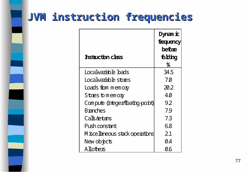
JVM JVM iinstruction nstruction ffrequenciesrequencies Dynamic frequency beforeInstruction class folding
%Local-variable loads 34.5Local-variable stores 7.0Loads from memory 20.2Stores to memory 4.0Compute (integer/floating-point) 9.2Branches 7.9Calls/returns 7.3Push constant 6.8Miscellaneous stack operations 2.1New objects 0.4All others 0.6

78
picoJava-I picoJava-I iinstruction nstruction ssetet
Not all instructions are implemented in hardware. Most instructions execute in 1 to 3 cycles. Of the instructions not implemented directly in hardware, those deemed critical
for system performance are implemented in microcode.– e.g. method invocation
The remaining instructions are emulated by core traps.– e.g. creating a new object
Additional to JVM: extended instructions in reserved opcode space with 2-byte opcodes (first one of the reserved virtual machine opcode bytes)– for implementation of system-level code (additional instructions not in
JVM)– JVM relies on library calls to the underlying operating system– extended byte codes: arbitrary load/store, cache management, internal
register access, miscellaneous

79
FoldingFolding
Cycle 1: iload_0
T
L0
TL0
L0
T+L0
L0
+ T+L0
L0
+T
L0
Cycle 2: iadd Cycle 1: iload_0, iadd
Without folding: the processor executes iload_0 during the first cycle and iadd during the second cycle.
With folding: iload_0 and iadd execute in the same cycle.

80
JVM instruction frequencies without and with foldingJVM instruction frequencies without and with folding Dynamic Dynamic frequency frequency before after InstructionsInstruction class folding folding folded
% % %Local-variable loads 34.5 24.4 10.1Local-variable stores 7.0 7.0 0.0Loads from memory 20.2 20.2 0.0Stores to memory 4.0 4.0 0.0Compute (integer/floating-point) 9.2 9.2 0.0Branches 7.9 7.9 0.0Calls/returns 7.3 7.3 0.0Push constant 6.8 2.0 4.8Miscellaneous stack operations 2.1 2.1 0.0New objects 0.4 0.4 0.0All others 0.6 0.6 0.0Total 100.0 85.1 14.9
81
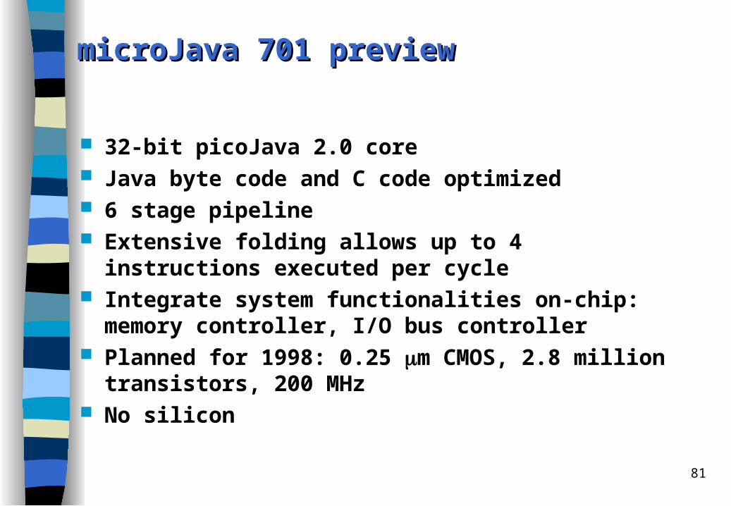
microJava 701 microJava 701 ppreviewreview
32-bit picoJava 2.0 core Java byte code and C code optimized 6 stage pipeline Extensive folding allows up to 4 instructions executed per cycle Integrate system functionalities on-chip: memory controller, I/O
bus controller Planned for 1998: 0.25 m CMOS, 2.8 million transistors, 200 MHz No silicon
82
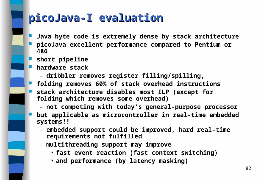
picoJava-I picoJava-I eevaluationvaluation
Java byte code is extremely dense by stack architecture picoJava excellent performance compared to Pentium or 486 short pipeline hardware stack
– dribbler removes register filling/spilling, folding removes 60% of stack overhead instructions stack architecture disables most ILP (except for folding which removes some
overhead) – not competing with today’s general-purpose processor
but applicable as microcontroller in real-time embedded systems!!– embedded support could be improved, hard real-time requirements not
fulfilled– multithreading support may improve
• fast event reaction (fast context switching)• and performance (by latency masking)

83
The Komodo The Komodo mmicrocontroller: icrocontroller: MT ("Multithreaded") Java MT ("Multithreaded") Java ccoreore start with picoJava-I-style pipeline, extend to multithreading
– multiple register sets multiple stack register sets,– IF is able to load from different PCs,
(PC, stack reg. ID) is propagated through pipeline– zero-latency context switch
external signals are handled by thread activation, not by interrupting instruction stream
different scheduling schemes– high priority thread runs with full speed, other threads in latency time slots – guaranteed percentage scheduling scheme
multithreading is additionally used whenever a latency arises, e.g. long latency operations
more information: http://goethe.ira.uka.de/~jkreuzin/komodo/komodoEng.html
84
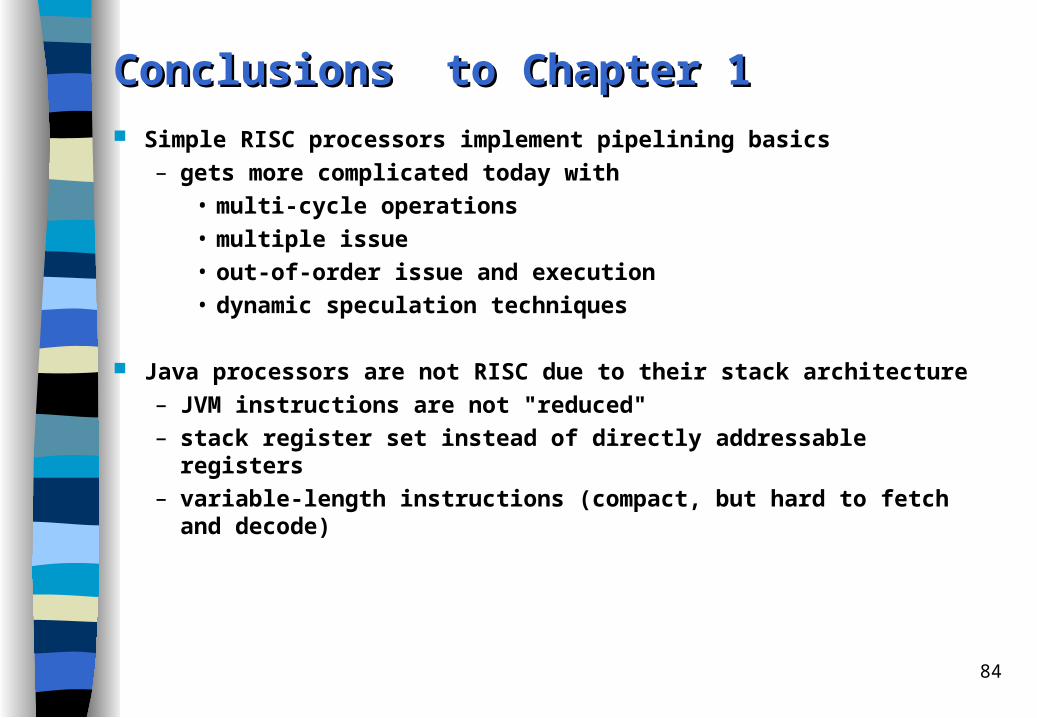
Conclusions to Conclusions to Chapter 1Chapter 1
Simple RISC processors implement pipelining basics– gets more complicated today with
• multi-cycle operations• multiple issue• out-of-order issue and execution• dynamic speculation techniques
Java processors are not RISC due to their stack architecture– JVM instructions are not "reduced"– stack register set instead of directly addressable registers– variable-length instructions (compact, but hard to fetch and decode)


![RISC AND PIPELINING RISC... · 2019. 10. 31. · RISC < C CISC [both < 1 with superscalar designs] a RISC will execute more instructions for a given benchmark than a CISC [ 10..30%]](https://img.dokumen.tips/doc/110x75/60d6340f7413895eda57bb56/risc-and-pipelining-risc-2019-10-31-risc-c-cisc-both-1-with.jpg)