Embed Size (px)
Citation preview
1
Basic Knowledge of Basic Knowledge of Electricity and Electronics Electricity and Electronics for Embedded Systems´ for Embedded Systems´
ProgrammersProgrammers

2
Elementary Electricity ConceptsElementary Electricity Concepts
Ohm´s Law: Ohm´s Law: • Current = Electromotive Force / ResistanceCurrent = Electromotive Force / Resistance• => I = E/R=> I = E/R• NOTE: An ideal voltage source (E) is considered to have NOTE: An ideal voltage source (E) is considered to have
ZERO internal resistance, that is, for an analysis of ZERO internal resistance, that is, for an analysis of resistance accross its terminals it is a short circuit.resistance accross its terminals it is a short circuit.
Series Circuit and Kirchoff´s Voltage LawSeries Circuit and Kirchoff´s Voltage Law The Three Rules of a Series Circuit:The Three Rules of a Series Circuit:
• Current has the same value at any point within a Current has the same value at any point within a series circuitseries circuit
• The values of the resistances of individual The values of the resistances of individual components add up to the total circuit resistance.components add up to the total circuit resistance.
Rt = R1 + R2 + R3Rt = R1 + R2 + R3• Voltage drops across the individual component Voltage drops across the individual component
resistances add up to the total applied voltage.resistances add up to the total applied voltage. E = V1 + V2 + V3E = V1 + V2 + V3
Resistive Divider – Class ExerciseResistive Divider – Class Exercise
E = 12 Volts
R = 2 KΩ
I = ?
E = 12 V
R3 = 2 K
I = ?
R1 = 2 K
R 2= 2 K
V1=?
V3=?

3
Elementary Electricity ConceptsElementary Electricity Concepts
Parallel Circuits and Kirchoff´s Current LawParallel Circuits and Kirchoff´s Current Law• A parallel Circuit provides two or more paths or A parallel Circuit provides two or more paths or
branches for circuit current. branches for circuit current.
The Three Rules of a Parallel Circuit:The Three Rules of a Parallel Circuit:• The same voltage is applied across each individual The same voltage is applied across each individual
branchbranch• The total current is equal to the sum of the The total current is equal to the sum of the
individual branch currents.individual branch currents.• The equivalent (or effective) resistance is equal to The equivalent (or effective) resistance is equal to
the applied voltage divided by the total current, the applied voltage divided by the total current, and this value is always less than the smallest and this value is always less than the smallest resistance contained in any one branch.resistance contained in any one branch.
E 12 V
R13Ω
R24Ω
R36Ω
I1 I2 I3
I total
I total = I1 + I2 + I3
Req = E / I total
1/Req = 1/R1 +1/R2 +1/R3

4
DC and AC Voltage and CurrentDC and AC Voltage and Current
DC voltage/CurrentDC voltage/Current• BatteriesBatteries• Electronic Equipment Power Supplies Electronic Equipment Power Supplies
convert AC voltage/current to DC convert AC voltage/current to DC voltage/currentvoltage/current
• Usually Low Power Low Voltage CircuitsUsually Low Power Low Voltage Circuits• Current Flows in Only One DirectionCurrent Flows in Only One Direction
AC Voltage/CurrentAC Voltage/Current• Provided by Electricity CompaniesProvided by Electricity Companies• Normal Illumination, Medium and High Power Normal Illumination, Medium and High Power
Equipment are usually driven by AC Equipment are usually driven by AC Voltage/CurrentVoltage/Current
• Current flows cyclically in both directions of Current flows cyclically in both directions of the circuit.the circuit.
• Vrms= 0.707 * Vpeak (0.707 * 179 V peak = Vrms= 0.707 * Vpeak (0.707 * 179 V peak = 127Vrms)127Vrms)
• frequency(f) = 1/T => 60 Hzfrequency(f) = 1/T => 60 Hz• Phase -> 0 degrees to 360 degreesPhase -> 0 degrees to 360 degrees
t
V
t
+V
-V
V peak = 179V
T

5
CapacitorCapacitor
CapacitorCapacitor
• Opposes changes in Voltage Between Opposes changes in Voltage Between Its terminals.Its terminals.
• Stores Electric ChargeStores Electric Charge
• Can be used to minimize (filter) the Can be used to minimize (filter) the ripple of analog signalsripple of analog signals
• Can be used to supply high Can be used to supply high instantaneous current to circuitsinstantaneous current to circuits
• Together with a Resistor can be used Together with a Resistor can be used to delay signalsto delay signals
VcE
10 V
R = 1 K
C 1uF
1
2
S
Switch in 1 Switch in 2
Vc
T = RC (Time to reach 63.2 % of Final Value During Charge) or 36.8% of Initial Value During Discharge
T – Seconds; R – Ohms; C - Farads

6
InductorInductor
InductorInductor
• Opposes Changes in Current accross Opposes Changes in Current accross its terminalsits terminals..
• Made by Winding a Conductor Made by Winding a Conductor around a core (magnetic material or around a core (magnetic material or insulated material)insulated material)
• Inductance measured in HenriesInductance measured in Henries
• Used in Transformers to Isolate one Used in Transformers to Isolate one Power Source from another.Power Source from another.
• Used in Transformers to Convert Used in Transformers to Convert from one voltage Range to Another from one voltage Range to Another and in Tuned LC Communication and in Tuned LC Communication circuits.circuits.
E
10 V
R = 1 K
L 1uH
1
2
S
I
Switch in 1 Switch in 2
Vr
Vr
T = L/R (Time to reach 63.2 % of Final Value) or 36.8% of Initial Value
T – Seconds; R – Ohms; L - Henries

7
Class Exercise -1Class Exercise -1
Draw a scheme with a resistor and a push button switch to reset a Draw a scheme with a resistor and a push button switch to reset a microcontroller. Consider a time constant of 20 ms (the time microcontroller. Consider a time constant of 20 ms (the time required to reach 63% of the maximum voltage) for a resistor of required to reach 63% of the maximum voltage) for a resistor of 100 Kohms. Calculate the capacitor required.100 Kohms. Calculate the capacitor required.• In scheme 1 the signal is normally at high (3 volts) and goes to zero volts when In scheme 1 the signal is normally at high (3 volts) and goes to zero volts when
the push button key is pressed (RESET AT LOW)the push button key is pressed (RESET AT LOW)
• In scheme 2 the signal is normally at zero volts and goes to 3 volts when the In scheme 2 the signal is normally at zero volts and goes to 3 volts when the push button key is pressed. (RESET AT HIGH)push button key is pressed. (RESET AT HIGH)
Draw a scheme with an ON-OFF switch (without central pole) that Draw a scheme with an ON-OFF switch (without central pole) that will indicate to the microcontroller that when in position A, that pin will indicate to the microcontroller that when in position A, that pin will be at zero volts (LOW) and when in position B it will be at 3 will be at zero volts (LOW) and when in position B it will be at 3 volts (HIGH).volts (HIGH).

8
Reactance and ImpedanceReactance and Impedance
Capacitive ReactanceCapacitive Reactance• The opposition to AC voltage changesThe opposition to AC voltage changes
offered by a capacitance (Xc or capacitive offered by a capacitance (Xc or capacitive reactance measured in ohms)reactance measured in ohms)
• Xc = 1 / (2Xc = 1 / (2π f C) ; f = frequency (Hz); C = π f C) ; f = frequency (Hz); C = Capacitance in FaradsCapacitance in Farads
Inductive ReactanceInductive Reactance• The opposition to AC current changesThe opposition to AC current changes
offered by an inductor (Xl or inductive offered by an inductor (Xl or inductive reactance measured in ohms)reactance measured in ohms)
• Xl = 2Xl = 2π f L ; f = frequency (Hz); L = π f L ; f = frequency (Hz); L = Inductance in HenriesInductance in Henries
Impedance and Vectorial AdditionImpedance and Vectorial Addition• The combined opposition to current The combined opposition to current
changes by resistance, inductance and changes by resistance, inductance and capacitance is called impedance and is capacitance is called impedance and is represented by the symbol Z.represented by the symbol Z.
R=8Ω Xl=5Ω
RXlZ= (R2+Xl2)
θ
R C
Xc
Xcθ
R
Z= (R2+Xc2)
R, L, C circuit:
Z= (R2+(Xl-Xc)2)

9
How can an AC Signal “Cross” a Capacitor?How can an AC Signal “Cross” a Capacitor?
On the other hand, the capacitor On the other hand, the capacitor blocks DC signals (or very low blocks DC signals (or very low frequency signals) frequency signals)
Vin = AC Signal –> f = 1 MHz
C = 1 uFarad
Xc = 1 / (2Xc = 1 / (2π f C)π f C)
Xc = 1/ (2 x 3.14 x 1 x 10Xc = 1/ (2 x 3.14 x 1 x 106 x 1 x 10 x 1 x 10-6-6))
Xc = 1/ (2x3.14) ohmsXc = 1/ (2x3.14) ohms
Xc = 0.16 ohms Xc = 0.16 ohms
Xc = ALMOST A SHORT CIRCUIT !Xc = ALMOST A SHORT CIRCUIT !
THUS, An AC signal can “cross” (or THUS, An AC signal can “cross” (or be propagated across) a capacitor, be propagated across) a capacitor, provided the frequency of the AC provided the frequency of the AC signal is high enough to make the signal is high enough to make the capacitor impedance very low. capacitor impedance very low.
C
XcVin Vout
R1
R2
+ 5V
0
4V
0
2V

10
Triple Phase TransformersTriple Phase Transformers
Transformers in Delta Transformers in Delta OrganisationOrganisation• Used to convert and Isolate Very Used to convert and Isolate Very
High Voltage (from Power Plants) to High Voltage (from Power Plants) to High Voltage in City DistributionHigh Voltage in City Distribution
Transformers in Star Transformers in Star OrganisationOrganisation• Used to Convert and Isolate from Used to Convert and Isolate from
High Voltage to Medium VoltageHigh Voltage to Medium Voltage
F1
F3
F2
N
F1
F2
F3
11
Power Supplies, No-Breaks, StabilizersPower Supplies, No-Breaks, Stabilizers
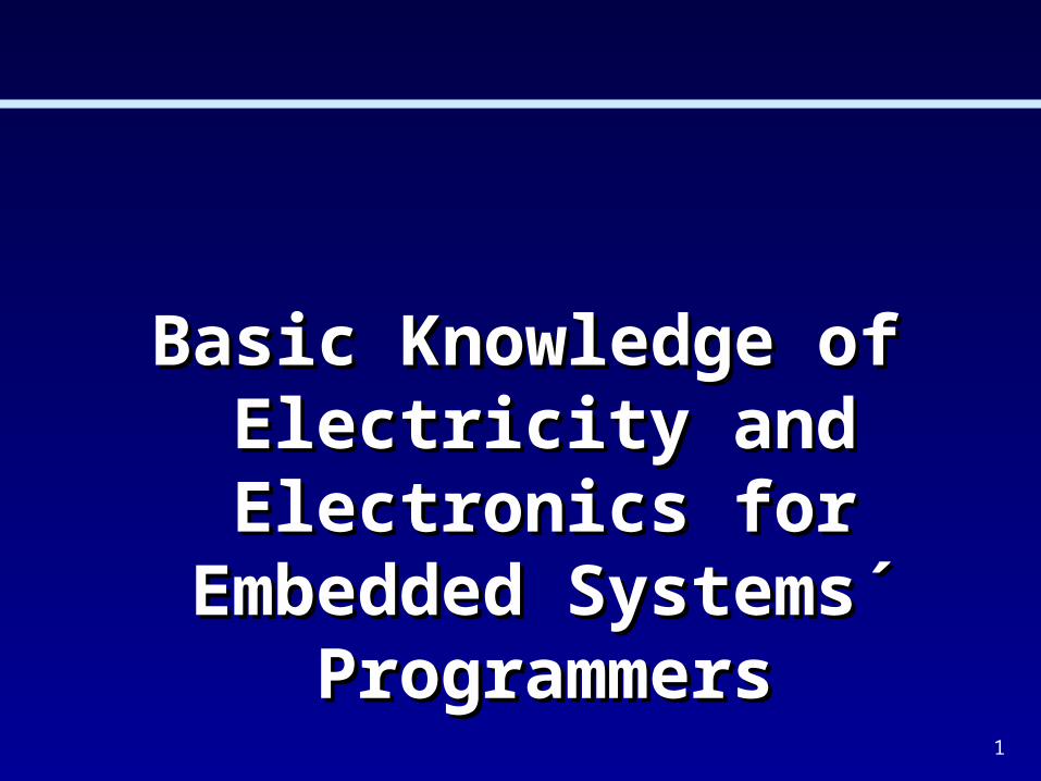
Power SuppliesPower Supplies• Convert AC Voltage to DC VoltageConvert AC Voltage to DC Voltage• Convert 127V AC to +5V, +12V, -12V, -5V DCConvert 127V AC to +5V, +12V, -12V, -5V DC
No-BreaksNo-Breaks• When there is AC Voltage, they Charge a BatteryWhen there is AC Voltage, they Charge a Battery• When there is no AC Voltage, The DC Voltage of the Battery is When there is no AC Voltage, The DC Voltage of the Battery is
Converted to AC Voltage to feed the ComputerConverted to AC Voltage to feed the Computer• A computer normally needs a Stabilizer and a No-Break.A computer normally needs a Stabilizer and a No-Break.
StabilizersStabilizers• Guarantee that AC Voltage Supplied to a Computer is kept within Guarantee that AC Voltage Supplied to a Computer is kept within
Certain Limits to Avoid Damaging the ComputerCertain Limits to Avoid Damaging the Computer
Note:Note:Common computer No-Breaks do not generate electricity from the Common computer No-Breaks do not generate electricity from the
battery when there is external power. They just generate battery when there is external power. They just generate electricity when there is no external power. Therefore, if the electricity when there is no external power. Therefore, if the external power varies its amplitude considerably, it is not good external power varies its amplitude considerably, it is not good for the computer. Due to this, a stabilizer is needed before the for the computer. Due to this, a stabilizer is needed before the No-Break.No-Break.

12
Switches, Relays, Solenoids, Power RelaysSwitches, Relays, Solenoids, Power Relays
Take to Class:Take to Class:
SwitchesSwitches• Some TypesSome Types
Relays, SolenoidsRelays, Solenoids• AC (127V) or DC Driven AC (127V) or DC Driven
(12V, 5V, etc) – The diode in (12V, 5V, etc) – The diode in parallel prevents a high parallel prevents a high peak voltage accross R peak voltage accross R when the circuit is opened.when the circuit is opened.
Three-Phase Power Three-Phase Power Relays or SolenoidsRelays or Solenoids
Push Button
1 2
21
OnOff
1
2
C
Central Pole
Same Types with Multiple Contacts
127V AC (Phase)
12V DC
R
Neutral
LAMP or Equipment
F2
F1
F3
F1 or F2 or F3
Neutral
Return F1
Return F2
Return F3

13
DebouncingDebouncing
When a switch (any type) changes When a switch (any type) changes state (on -> off or off -> on), it presents state (on -> off or off -> on), it presents a mechanical bouncing which a mechanical bouncing which generates a signal similar to the one generates a signal similar to the one shown at the right.shown at the right.
The resistor R is needed because the The resistor R is needed because the signal S can not be left “floating” in na signal S can not be left “floating” in na undefined state when the switch undefined state when the switch changes from state 1 to 2.changes from state 1 to 2.
Without debouncing the signal can Without debouncing the signal can generate several interrupts (or status generate several interrupts (or status changes) corresponding to just one changes) corresponding to just one action.action.
Debouncing consists in “Filtering” the Debouncing consists in “Filtering” the signal S so that a proper operation of signal S so that a proper operation of the switch action is sensed.the switch action is sensed.
Debouncing can be done in hardware Debouncing can be done in hardware of softwareof software
Microcontroller1
2
C
5V
R
5V S
Read Key (should be stable)
Techniques that can be used:
-If status loop: after first status change, program timer and after elapsed time read key status.
-If Interrupt: on first interrupt program timer which will interrupt after elapsed time. Then read key status.
Δt Δt

14
Logic Circuits using Switches and RelaysLogic Circuits using Switches and Relays

15
GroundingGrounding
Grounding ReferenceGrounding Reference• Two Equipments(circuits) can communicate Two Equipments(circuits) can communicate
either using commom mode signals or either using commom mode signals or differential signals. The most common are differential signals. The most common are common mode signals. In this case a common mode signals. In this case a common reference wire is established and common reference wire is established and voltages are related to that common wire, voltages are related to that common wire, which is usually termed Ground wire.which is usually termed Ground wire.
Safety GroundSafety Ground• Safety ground is a wire employed to connect Safety ground is a wire employed to connect
metalic parts of the equipment to the earth´s metalic parts of the equipment to the earth´s ground. This is done to prevent accidents by ground. This is done to prevent accidents by persons touching metalic parts with voltage persons touching metalic parts with voltage levels (due to defective parts)levels (due to defective parts)
Neutral WireNeutral Wire• Comes from the street transformer (where is Comes from the street transformer (where is
earth grounded) but can not be usedearth grounded) but can not be used for for safety ground. A separate safety ground is safety ground. A separate safety ground is required.required.
Equip.
A
Equip.
BCommon (ground)
Signals
Equip.
A
Equip.
BCommon (ground)
Signals
Safety Ground
Neutral Hot Wire
Safety ground

16
Volt – Ohm - Meter (VOM) or MultimeterVolt – Ohm - Meter (VOM) or Multimeter

17
V.O.M MeasurementsV.O.M Measurements

18
Some Common Electronic DevicesSome Common Electronic Devices
DiodeDiode• Used to allow current in just one direction, to rectify AC Used to allow current in just one direction, to rectify AC
waveforms. When current flows in the correct direction, waveforms. When current flows in the correct direction, voltage drop across it is approximately 0.65V, almost voltage drop across it is approximately 0.65V, almost independently of the current. When voltage is reversed, it independently of the current. When voltage is reversed, it acts like an enormous resistor. A LED is also a diode but acts like an enormous resistor. A LED is also a diode but the voltage drop across its terminals is usually 1.5 Volts, the voltage drop across its terminals is usually 1.5 Volts, instead of 0.65 Volts.instead of 0.65 Volts.
Zener DiodeZener Diode• Used to establish a certain reference voltage in a circuit Used to establish a certain reference voltage in a circuit
section, almost independently of the reverse current flow section, almost independently of the reverse current flow across it. Reverse voltage depends on the type of zener across it. Reverse voltage depends on the type of zener diode. (direct voltage drop is 0.65 V)diode. (direct voltage drop is 0.65 V)
CrystalCrystal• Used to provide highly accurate clock oscillatorsUsed to provide highly accurate clock oscillators
Light Dependant Resistor (LDR)Light Dependant Resistor (LDR)• Resistance varies according to lightResistance varies according to light
Current flow
V
Vz
XTAL
A B

19
Diode Voltage x Currrent CharacteristicsDiode Voltage x Currrent Characteristics

20
Class Exercise -2Class Exercise -2
Draw the output waveform for the circuit belowDraw the output waveform for the circuit below
Sinusoidal
Generator
0
Vout ?

21
Class Exercise -3Class Exercise -3
Common LEDs (Light Emmitting Diodes) can be turned “ON” with a current Common LEDs (Light Emmitting Diodes) can be turned “ON” with a current between 5mA and 10mA.between 5mA and 10mA.
Microcontrollers Can Have Currents in Output pins between 2mA and 20ma Microcontrollers Can Have Currents in Output pins between 2mA and 20ma when in “LOW” Level (IOwhen in “LOW” Level (IOL) and currents between 2mA and 10mA when in ) and currents between 2mA and 10mA when in “HIGH” level (IO“HIGH” level (IOH). ). Note that when the output pin of the microcontroller is at Note that when the output pin of the microcontroller is at 0 volts level the current flows into the pin and when it is at 3 volts, the 0 volts level the current flows into the pin and when it is at 3 volts, the current flows out of the pin.current flows out of the pin.
In order to protect the Microcontroller to not exceed its output current and In order to protect the Microcontroller to not exceed its output current and also to protect the LED to not exceed the current across its terminals, a also to protect the LED to not exceed the current across its terminals, a resistor in series with the LED is used.resistor in series with the LED is used.
Draw a scheme to connect a LED to an output pin of a microcontroller, Draw a scheme to connect a LED to an output pin of a microcontroller, turning the LED “ON” when the output pin is at logic “0” and turning it turning the LED “ON” when the output pin is at logic “0” and turning it “ON” when the output pin is at logic “1”.“ON” when the output pin is at logic “1”.
Calculate the resistor to limit the current across the LED to 5 mA. Consider Calculate the resistor to limit the current across the LED to 5 mA. Consider that the power supply is 3 Volts. Remember that there is a voltage drop that the power supply is 3 Volts. Remember that there is a voltage drop across the LED when the current is flowing in the correct direction.across the LED when the current is flowing in the correct direction.

22
V I R Ohm’s Law
Kirchoff’s Voltage Law – The algebraic sum of all voltage rises and voltage drops around a closed loop must equal zero
Kirchoff’s Current Law – The algebraic sum of all currents entering and leaving a node must equal zero
V 0
I IIN OU T
Series Equivalent
R R R REQ N 1 2 . . .
Parallel Equivalent
1 1 1 1
1 2R R R REQ N
. . .
Remember:

23
Mesh AnalysisMesh Analysis
20V100 100
300
200500I1 I2
I3R1
R4
R5
R3
R2
Loop1: - 20 + 100 (I1-I3) + 500 (I1-I2) = 0
Loop2: 500 (I2-I1) + 100 (I2-I3) + 200 (I2) = 0
Loop3: 300 (I3) + 100 (I3-I2) + 100 (I3-I1) = 0
System with 3 equations – Solve using determinants
I1=85.7mA ; I2 = 57.14mA; I3 = 28.57mA
• First, determine the number of closed loops and then draw the direction of the currents around the loops.
• Second, identify the plus and minus voltage on each resistor, according to the currents flowing across them.
• Third, traverse the loop associating a plus or minus sign, depending on the the entrance sign, when traversing the loop.
24
Thevenin´s TheoremThevenin´s Theorem
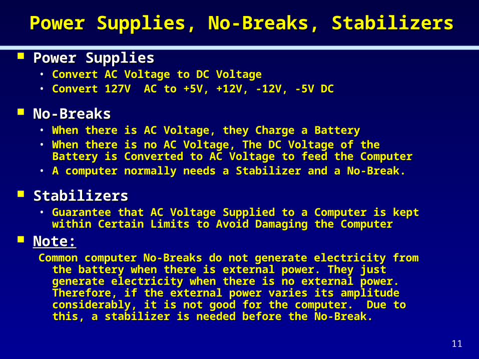
Thevenin´s Theorem: Any two terminal circuit can be replaced by a resistance, equal to the resistance measured across the two terminals, in series with a voltage source, equal to the open circuit voltage accross the two terminals.
What For ??: => The Key objective is to find a simple circuit that is equivalent to a more complex one. For example: Obtain an equivalent circuit between terminals A and B that is simpler than the circuit on the right:
Step1 : Find Vth. Because the terminals are open, there will be no current flowing through the 4 ohms resistor, and therefore, no voltage drop accross it. So, the open circuit voltage (Vth) will be equal the voltage across the 10 resistor. Thus, by the voltage divider rule:
Vth = 10V.
Step2 : Find Rth (the resistance seen looking into terminals A and B). Replacing the voltage source with its ideal internal resistance (zero ohms), we find that:
Rth = 4 + 15 // 2 = 10
25V
15 4
2
A
B
Vth
Rth A
B15 4
2
A
B
Rth
10V
10 A
B

TRANSITOR - PNPTRANSITOR - PNP
Emitter
Base
Collector
Current

Bipolar Transistor -PNPBipolar Transistor -PNP
n n
p
p
Emitter
Base
Collector
Emitter
Base
Collector
Current
Ie = Ic + Ib

Bipolar Transistor - NPNBipolar Transistor - NPN
Emitter
Base
Collector
p p
n
n
Emitter
Base
Collector
Ie = Ic + Ib

28
• NPN / PNP Block Diagrams
Bipolar Transistor ConstructionBipolar Transistor Construction
Emitter
Emitter
N P N
P N P
Collector
Base
Base
Collector

29
+ N P NEmitter
Base +
-
FB RB
Bipolar Transistor Biasing (NPN)Bipolar Transistor Biasing (NPN)
Collector

30
P N PEmitter Collector
Base
+
+
-
FB RB
Bipolar Transistor Biasing (PNP)Bipolar Transistor Biasing (PNP)

31
Transistor Characteristic CurveTransistor Characteristic Curve
IC
VCE
Q-Point
IB
0 uA
10 uA
20 uA
30 uA
40 uA
50 uA
60 uA
70 uA80 uA90 uA
Saturation
Cutoff
32
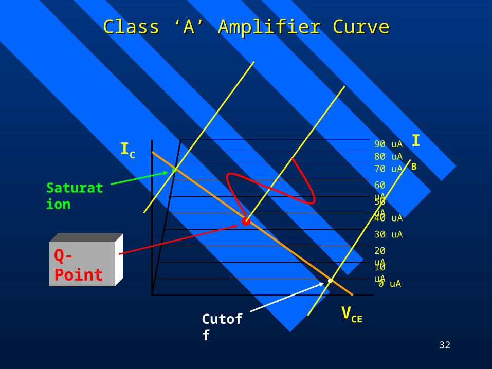
Class ‘A’ Amplifier CurveClass ‘A’ Amplifier Curve
IC
VCE
IB
0 uA
10 uA
20 uA
30 uA
40 uA
50 uA
60 uA
70 uA80 uA90 uA
Saturation
Cutoff
Q-Point
33
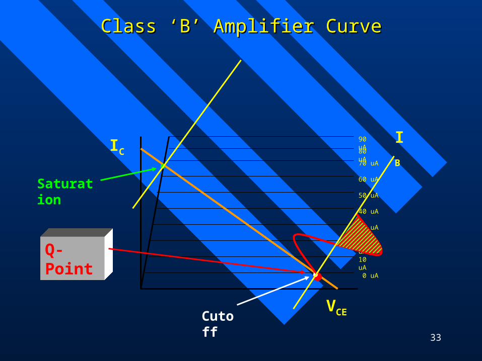
Class ‘B’ Amplifier CurveClass ‘B’ Amplifier Curve
IC
VCE
IB
0 uA
10 uA
20 uA
30 uA
40 uA
50 uA
60 uA
70 uA
80 uA
90 uA
Saturation
Cutoff
Q-Point

34
Analyzing The Transistor Operation Region: Analyzing The Transistor Operation Region: Conduction, Saturation or Cutt-OffConduction, Saturation or Cutt-Off
Conduction Region Conduction Region ––For any transistor to conduct, two things must occur. The emitter - base PN junction must be forward biased. The base - collector PN junction must be reverse biased. In this region the transistor presents an amplification in current (gain)
or “ß”, which relates collector current (Ic) and base current (Ib) according to the following equation:
Ic = ß Ib (Equation 1) It is also known that Ie = Ic + Ib (Equation 2) Then: Ie = (ß Ib) + Ib => Ie = (ß + 1) Ib (Equation 3)
Cut-Off RegionCut-Off Region – When Ic is almost zero and the absolute value of the – When Ic is almost zero and the absolute value of the Base-Emitter voltage is lower than 0.65 V (for silicon transistors). Base-Emitter voltage is lower than 0.65 V (for silicon transistors). When the When the transistor reaches this region, the equations above are no longer validtransistor reaches this region, the equations above are no longer valid..
Saturation RegionSaturation Region – When Vce is almost zero and the absolute value of the – When Vce is almost zero and the absolute value of the Base-Emitter voltage is larger than 0,65 V (for silicon transistors). Base-Emitter voltage is larger than 0,65 V (for silicon transistors). When the When the transistor reaches this region, the equations above are no longer valid.transistor reaches this region, the equations above are no longer valid.

35
Bipolar Transistor Operation (PNP)Bipolar Transistor Operation (PNP)
•90% of the current carriers passes through the reverse biased base - collector PN junction and enter the collector of the transistor.
•10% of the current carriers exit transistor through the base.
•The opposite is true for a NPN transistor.

36
• The transistor below is biased such that there is a degree of forward bias on the base - emitter PN junction.
• Any input received will change the magnitude of forward bias & the amount of current flow through the transistor.
Amplifier OperationAmplifier Operation
RB
RC
Q1
+
0
+VCC
Input Signal
+
0
Output Signal

37
Amplifier Electric Switch OperationAmplifier Electric Switch Operation
•When the input signal is large enough, the transistor can be driven into saturation & cutoff which will make the transistor act as an electronic switch.
•Saturation - The region of transistor operation where a further increase in the input signal causes no further increase in the output signal.
•Cutoff - Region of transistor operation where the input signal is reduced to a point where minimum transistor biasing cannot be maintained => the transistor is no longer biased to conduct. (no current flows)

38
Amplifier Electric Switch OperationAmplifier Electric Switch Operation
–Transistor Q-point•Quiescent point : region of transistor operation where the biasing on the transistor causes operation / output with no input signal applied.
–The biasing on the transistor determines the amount of time an output signal is developed.
–Transistor Characteristic Curve•This curve displays all values of IC and VCE for a given circuit. It is curve is based on the level of DC biasing that is provided to the transistor prior to the application of an input signal.
–The values of the circuit resistors, and VCC will determine the location of the Q-point.

39
Some Common Electronic DevicesSome Common Electronic Devices
Bipolar Bipolar
TransistorTransistor
(NPN)(NPN)
e.g.: e.g.: BC237, BC237, BC 337, BC 547, BC 337, BC 547, BC 557, 2N2222 BC 557, 2N2222 (NPN and PNP)(NPN and PNP)
MOS MOS
TransistorTransistor
(N type)(N type)
Drain
Gate
Source

40
Determining Saturation, Cutoff or Conduction Determining Saturation, Cutoff or Conduction
Vce=?
+ 10V
Rc10K
BC
E
Ic
IeIb Vbe
R1
100K
Vce=?
+ 10V
Rc10K
BC
E
Ic
IeIb Vbe
R1
100K
Determine the operation Region of the circuit below:
Simplified Model
Assume Transistor Current Gain = ß = 100 and Vbe = 0.65V
Ie = Ic + Ib
Ic = ß x Ib = 100 Ib
Calculating Ib:
10 V = Vbe V + Ib x 100 x 103 (10 – 0.65) V = Ib x 100 x 103 => Ib = .0935 mA
Thus Ic = 100 x Ib = 9.35 mA
10 V = Vce + Ic x 10 x 103 => Vce = - 83.5 V < 0V !!
In reality Vce does not go negative because when it is almost zero (saturation), the current gain (ß) does not apply any more and Vce sets at 0 volts.
Thus the transistor is SATURATED

41
Building Logic Gates with Transistors & Building Logic Gates with Transistors & ResistorsResistors

TransformersTransformers
A transformer is a passive electronics A transformer is a passive electronics component and consists of a pair of wire component and consists of a pair of wire coils coupled together with an iron core. coils coupled together with an iron core. The input coil is called the primary coil The input coil is called the primary coil and the output coil is called the secondary and the output coil is called the secondary coil. coil.

TransformersTransformers
Transformer Voltages
-150
-100
-50
0
50
100
150
0 1 2 3 4 5 6 7 8Vo
lts Primary
Seconday

FiltersFilters
Plot of Transformer Voltages: Left side, primary; Right side, secondary
0
2
4
6
8
10
12
14
0 2 4 6 8 10
Vo
lts
Series1

Power SupplyPower Supply
Transformer
Unrectified
-15
-10
-5
0
5
10
15
0 1 2 3 4 5 6 7 8
Vo
lts
Unrectified
-15
-10
-5
0
5
10
15
0 1 2 3 4 5 6 7 8
Volts
Rectifier
Rectified
0
10
20
0 2 4 6 8
Volts
Filter
Effect of Filter
0
2
4
6
8
10
12
0 1 2 3 4 5 6 7 8
Vo
lts

46
Full-Wave RectifierFull-Wave Rectifier
bridge
Rectified
0
10
20
0 2 4 6 8
Volts

47
Full-Wave RectifierFull-Wave Rectifier
Rectified
0
10
20
0 2 4 6 8
Volts

48
Power Supply Capacitor Filter and RegulatorPower Supply Capacitor Filter and Regulator
REGULADOR
7805Vem dos Diodos
Retificadores - IN
OUT
12V 5V
TERRA
+ 5V DC

49
Interface Circuits with the Real WorldInterface Circuits with the Real World
Switches and Relays – already shownSwitches and Relays – already shown
Keyboard with No Logic Keyboard with No Logic
Keyboard with LogicKeyboard with Logic
Light Emitting Diodes (LEDs) Light Emitting Diodes (LEDs)
Seven Segment Displays – can be driven Seven Segment Displays – can be driven by resistors connected to normal logic – by resistors connected to normal logic – check currentcheck current
Liquid Crystal Displays – 20 or 40 columns Liquid Crystal Displays – 20 or 40 columns by 2 to 4 rows – some have serial interfaceby 2 to 4 rows – some have serial interface

50
Example 1 – Driving a 7-Segment DisplayExample 1 – Driving a 7-Segment Display“Common Anode”“Common Anode”
a b c d e f g
v+
a b c d e f g
v+
8 x 180 R
+5V
Is
Is = (5V – 1.5V) / 180R = 20ma

51
Example 1 – Driving a 7-Segment DisplayExample 1 – Driving a 7-Segment Display“Common Anode”“Common Anode”
a b c d e f g
v+
a b c d e f g
v+
8 x 180 R
+5V
10K
10K
Id
ItIt
Id = (5V – 1.5V) / 180R = 20ma

52
Interface Circuits with the Real WorldInterface Circuits with the Real World
Transistor-Transistor Logic (TTL) (5 Transistor-Transistor Logic (TTL) (5 volts) to other voltages Converters: volts) to other voltages Converters: 7406, 7407 (open collector)7406, 7407 (open collector)
TTL (5 volts) to RS232C (serial port -> TTL (5 volts) to RS232C (serial port -> +12V to –12V) converters: MAX 232, +12V to –12V) converters: MAX 232, 1489, 14881489, 1488
TTL common mode to RS422 TTL common mode to RS422 Differential mode – Higher speed than Differential mode – Higher speed than RS232 and higher noise immunity RS232 and higher noise immunity
I
+5v
0v
0v
+12v
-12v
O.C. Inverter (7406)
Max 232

53
Interface Circuits with the Real WorldInterface Circuits with the Real World
Digital to Analog (D/A) Digital to Analog (D/A) ConverterConverter
Analog to Digital (A/D) Analog to Digital (A/D) ConverterConverter
REGISTER
8/12/16-bit Data
Clock
D/A
Analog Signal
REGISTER
Digital Data
A/D
Analog Signal
Clock

54
Programmable Logic Arrays (PLAs and PALs)Programmable Logic Arrays (PLAs and PALs)
F= (A.B) + (A.C.D) + (D.E) + (A.F) + (B.E.F) F= (A.B) + (A.C.D) + (D.E) + (A.F) + (B.E.F)
O3 = I0.I2./I3 + I3.I5 + /I2.I4 + /I4.I5 + /I5.I1O3 = I0.I2./I3 + I3.I5 + /I2.I4 + /I4.I5 + /I5.I1
CI-2
BEF
D
AC
F
A
E
D
B
A
F
CI-1 CI-3 CI-4

55
Field Programmable Gate Arrays (FPGAs)Field Programmable Gate Arrays (FPGAs)
56
FLASH MemoryFLASH Memory
Flash memory is a form of Flash memory is a form of EEPROMEEPROM that allows multiple that allows multiple memorymemory locations to be erased or written locations to be erased or written in one programming operation. Normal EEPROM only allows one location at a time to be in one programming operation. Normal EEPROM only allows one location at a time to be erased or written, meaning that flash can operate at higher effective speeds when the systems erased or written, meaning that flash can operate at higher effective speeds when the systems using it read and write to different locations at the same time. All types of flash memory and using it read and write to different locations at the same time. All types of flash memory and EEPROM wear out after a certain number of erase operations.EEPROM wear out after a certain number of erase operations.
Flash memory is made in two forms: Flash memory is made in two forms: NORNOR flash and NAND flash. The names refer to the type of flash and NAND flash. The names refer to the type of logic gate used in each storage cell.logic gate used in each storage cell.
NOR flashNOR flash was the first type to be developed, invented by Intel in 1988. It has long erase and write was the first type to be developed, invented by Intel in 1988. It has long erase and write times, but has a full address/data (memory) interface that allows random access to any times, but has a full address/data (memory) interface that allows random access to any location. location. This makes it suitable for storage of program codeThis makes it suitable for storage of program code that needs to be infrequently that needs to be infrequently updated, as in digital cameras and PDAs. Its endurance is 10,000 to 100,000 erase cycles. updated, as in digital cameras and PDAs. Its endurance is 10,000 to 100,000 erase cycles. NOR-based flash is the basis of early flash-based removable media; Compact Flash and NOR-based flash is the basis of early flash-based removable media; Compact Flash and SmartMedia are both based on it.SmartMedia are both based on it.
NAND flashNAND flash from Toshiba followed in 1989. It has faster erase and write times, higher density, and from Toshiba followed in 1989. It has faster erase and write times, higher density, and lower cost per bit than NOR flash, and ten times the endurance. However its I/O interface lower cost per bit than NOR flash, and ten times the endurance. However its I/O interface allows only sequential access to data. This makes it allows only sequential access to data. This makes it suitable for mass-storage devicessuitable for mass-storage devices such such as PC cards and various memory cards, and somewhat less useful for computer memory. as PC cards and various memory cards, and somewhat less useful for computer memory. NAND-based flash has led to several much smaller removable media formats, MMC, Secure NAND-based flash has led to several much smaller removable media formats, MMC, Secure Digital and Memory Stick.Digital and Memory Stick.
Flash memory forms the core of the removable USB interface storage devices known as Flash memory forms the core of the removable USB interface storage devices known as keydrives.keydrives.
NOR Flash uses hot electron injection for writing and tunnel release for erasing. NAND Flash uses NOR Flash uses hot electron injection for writing and tunnel release for erasing. NAND Flash uses tunnel injection for writing and tunnel release for erasing. tunnel injection for writing and tunnel release for erasing. Flash memory is erased through a Flash memory is erased through a mechanism called Fowler-Nordheim tunneling - a quantum mechanical tunneling process.mechanism called Fowler-Nordheim tunneling - a quantum mechanical tunneling process.