Embed Size (px)
Citation preview

1
Real Time Building Identification System Development Using Aerial Imagery
Presented by:Mr. Duong Van HIEU RSA028033
Examination Committee:Dr. Kiyoshi Honda ChairmanDr. Xiaoyong Chen MemberDr. Frederic Borne MemberDr. Manukid Parnichkun Member
1. Background
2D GIS databases are available, especially building
geometric information on the buildings contains polygonal shape and the number of floors (height)
Constructing a 3D building model is possible
Availability of small and low-power consumer devices (PDA, GPS, Tilt sensor and Digital Camera) and network access capabilitiesA real-time system development is feasible

2
1. Background (cont.)Access building information based on landscape image will give very intuitive interface Help people to know and grasp what is happening in the real world and help their decision making.Tourist support systemUrban disaster Mitigation; Fire, Earthquakes and etc.AircraftBig market in recent time
3. Objectives
To develop a core algorithm for real time building identification system by linking images from high places ( airplane or high buildings) to existing 2D GIS building database
(1). Design building identification system.> Images are captured from high places> A link between images and 2D GIS building data
are automatically generated
(2). Develop matching algorithm with short processing time.

3
Reference Image CreationData Acquisition
4. Methodology - System Overview
Rectification byLine Matching
Coordinate Conversion
Real Time Data Acquisition
Digital Camera
Digital Image
Approximate
Camera Position
(X,Y,Z), GPS
Camera Attitude (ω,ϕ,κ), Electronic Compass
2D Building data with ID
numbers
3D Computer Graphicswith (X,Y,Z) and (ω,ϕ,κ)
4. Methodology - System Overview
Rectification byLine Matching
Geo-rectified imagewith (X,Y Z)and (ω,ϕ,κ)
Link Creation & Display
2319
Bld_id: 2319Name: …Owner: ……
GIS Building Database

4
4. Study AreaViewing Point
Phathum Wan District
BaiYoke Sky2X= 1,520,785.552Y= 666,868.817Z = 275m
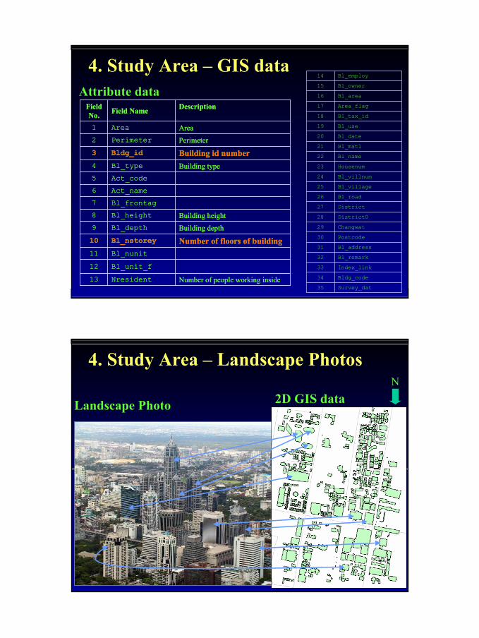
4. Study Area – GIS data
Phathum Wan District
BaiYoke Sky2X= 1,520,785.552Y= 666,868.817Z = 275m
Viewing Point
Spatial data (1:4000 map scale)
Provided by MapPointAsia Company
5
4. Study Area – GIS dataAttribute data
Number of people working insideNresident13Bl_unit_f12Bl_nunit11
Number of floors of buildingBl_nstorey10Building depthBl_depth9Building heightBl_height8
Bl_frontag7Act_name 6Act_code 5
Building typeBl_type4Building id numberBldg_id3PerimeterPerimeter2AreaArea1
DescriptionField NameField No.
Survey_dat35Bldg_code34Index_link33Bl_remark32Bl_address31Postcode30Changwat29District028District27Bl_road26Bl_village25Bl_villnum24Housenum23Bl_name22Bl_matl21Bl_date20Bl_use19Bl_tax_id18Area_flag17Bl_area16Bl_owner15Bl_employ14
Number of people working insideNresident13Bl_unit_f12Bl_nunit11
Number of floors of buildingBl_nstorey10Building depthBl_depth9Building heightBl_height8
Bl_frontag7Act_name 6Act_code 5
Building typeBl_type4Building id numberBldg_id3PerimeterPerimeter2AreaArea1
DescriptionField NameField No.
4. Study Area – Landscape Photos
Landscape Photo 2D GIS dataN

6
1. Edge Detection2. Thresholding3. Vertical Edge Detection
by Morphology
3D Computer Graphicswith (X,Y,Z) and (ω,ϕ,κ)
(Reference Image)
Flow chart of System
Digital Camera Image(Original Image)
4. Mask Image Creation
1. Edge Detection2. Thresholding
Building Selection
7s
10s
2s2s2s
2s2s
5s
Reference Edge Image(Binary)
Extract True Building Edges By Hough Transform
Original Edge Image with mask(Binary)
5. Methodology (cont.)
5. Masking Original Edge Image
Line Matching by Image Correlation
Rectified Original Image
Building ID Display
Morphology to reduce texture
6s
2s
10s
20s
3s
1s

7
Computer Digital Camera
Electronic Compass(ω,ϕ,κ)
GPS (X,Y,Z)
Data Acquisition System
Digital Landscape ImagePhathum Wan BuildingsImage size (1856x1392) Focus length = 18.1mmX= 1,520,785.552Y= 666,868.817Z= 275mω= -7.590, ϕ=154.6, κ=0

8
X= 1,520,785.552Y= 666,868.817Z = 275mω = -7.590ϕ = 154.6κ = 0
Phathum Wan Buildings
Same image size (1856x1392)
& Viewing angle (FOV)
Reference Image-3D CG with (X,Y,Z) & (ω,ϕ,κ)
Criteria for Building SelectionVisibility=B/A > 0.7
A
A
B
ID:2319
No. of Floor = 23
Height = 4*23 =92
Number of Floor >20
1
2
Number of obstructive objects = 0
9
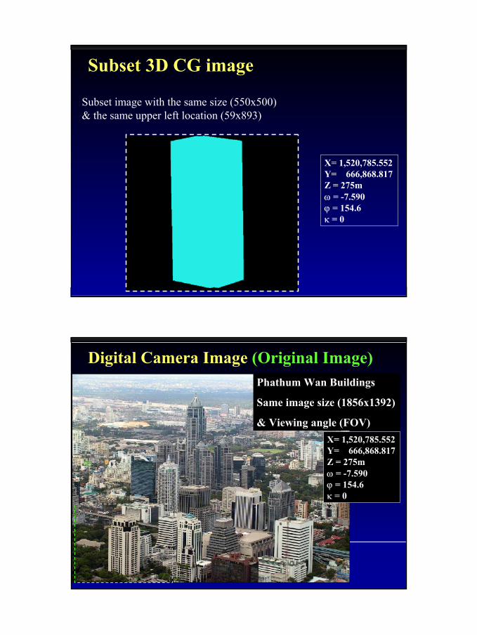
Subset 3D CG image
X= 1,520,785.552Y= 666,868.817Z = 275mω = -7.590ϕ = 154.6κ = 0
Subset image with the same size (550x500) & the same upper left location (59x893)
Digital Camera Image (Original Image)Phathum Wan Buildings
Same image size (1856x1392)
& Viewing angle (FOV)X= 1,520,785.552Y= 666,868.817Z = 275mω = -7.590ϕ = 154.6κ = 0

10
Subset 3D Digital Camera Image image
X= 1,520,785.552Y= 666,868.817Z = 275mω = -7.590ϕ = 154.6κ = 0
Subset image with the same size (550x500) & the same upper left location (59x893)
Edge Detection & Thresholding
Edge Detection by Robert filter Thresholding
Binary Edge Image

11
5. Result (cont.) 1. Edge Detection2. Thresholding3. Vertical Edge Detection
by Morphology
Thresholding & Vertical Edge Detection (Openning)
Edge Detection by Robert filter
Mask Image Creation
Some assumption of accuracyAzimuth angle is measured by electronic compass (1 degree accuracy).Altimeter is used for height measurement with 10m accuracy.Elevation angle ω is estimated by manually, around -5 degree (downward).

12
Mask Image CreationBased on heading information accuracy of tilt sensor and distance from viewing point to target buildingα = ±0.5, d=1100m
d=1100m
α: ±0.5
Target Building
Viewing Point
Delta_Xs
Delta_Xs = α * d = 1100*0.5*π/180 = 10 m
Mask Image Creation
GIS Building Edge
Actual building in the landscape image
The difference between GIS and actual building
Delta_Xg = 10m
10 m10 m

13
Mask Image Creation
Focus Point
Viewing AngleVAh,VAv
Focus Length
Image Sizew=1856h=1392
f=18.1mm
CCD
VA = (tan-1 (a / f)) x 2VA: Viewing anglea: ½ of CCD Sizef: Focus length
4.8 mm
6.4 mm
d=1100Dx(m) = (w/2)*(d/f) = 194m1m = 1856/2/Dx(m) ~ 5 pixels
Delta_Xs = Delta_Xg = 50 pixelsDx
Mask Image Creation
d=1100m
α
Target Building
Viewing Point
Delta_Xs
Delta_Xg
Mask Area
Mask Area Width = = 2*(Delta_Xs + Delta_Xg)= 200 pixels

14
Hough Transform - Right Mask Area
Convert back into image SpaceMax Value = 93r = 490, theta = 1
r = x*cosθ + y*sinθ
θ
Hough Space
r
Image Space
y
x
Line Matching by Image Correlation
Shift X1 = -40Rotation1 = 0.8 degree
Red : Left Edge of Reference ImageGreen : Left Edge of Original Image
Shift X Range = -100 to +100Rotation Range -3 to +3, step 0.1 degree

15
Line Matching by Image Correlation
Shift X2 = -22Rotation2 = 0.7 degree
Red : Right Edge of Reference ImageGreen : Right edge of Original Image
Shift X Range = -100 to +100Rotation Range -3 to +3, step 0.1 degree
Matching parameters
Shift X = -31Rotation = 0.75 degree
Shift X Range = -100 to +100Rotation Range -3 to +3, step 0.1 degree
Image Not Rectified Yet

16
Rectified Original ImageShift X = -31Rotation = 0.75 degree
Original Landscape Image
Rectified Image
Rectified Original ImageShift X = -31Rotation = 0.75 degree
Rectified Image& Reference Image
Original Landscape Image& Reference Image

17
6. Accuracy Assessment – Area Method
Extraction of true shape of real building as reference
Accuracy Assessment – Area MethodOverlay true shape of real building with 3DCG building shape
Landscape building iswithin completely 3D CG building.Accuracy is 100%

18
Rectified Whole Landscape ImageShift X = -31Rotation = 0.75 degree
6. Accuracy Assessment – Center PointExtract shape of 16 buildings by manually

19
6. Accuracy Assessment – Center PointCenter point image
6. Accuracy Assessment – Center Point

20
6. Accuracy Assessment - CenterPointCorrectIncorrect Accuracy = 93.75%
Correct: 15 Incorrect: 1
6. Accuracy Assessment – Center PointOverlaying Original Landscape Image and Center Point Image

21
6. Accuracy Assessment - CenterPoint
7. Conclusion
(1). Core algorithm for matching digital camera image and 3D from 2D GIS was developed. Digital Image from BaiYoke Sky to Pathumwan was georectified
(2). The accuracy for identification was acceptable at 93.75% which was measured at the center of the gravity

22
8. Problems and Future Work
(1). 2D GIS data accuracyShape; Foot print and 3D building shape have big difference and it affects the matching accuracy greatly.