Embed Size (px)
Citation preview

1ATM -
All rights reserved. No part of this publication and file may be reproduced, stored in a retrieval system, or transmitted in any form or by any means, electronic, mechanical, photocopying, recording or otherwise, without prior written permission of Professor Nen-Fu Huang (E-mail: [email protected]).
ATM Networks

2ATM -
An Overview of ATM
ATM is Asynchronous Transfer Mode. A technology for multiplexing fixed-length (53
octets) cells from a variety of sources to a variety of remote locations.
Capable of moving data at a wide range of speeds. Capable of handling data from a variety of media
(e.g. voice, video, and data) using a single interface.
ATM is a connection-oriented protocol. Connections are established between ATM service
users, (e.g. a workstation with an ATM interface or a call setup process running on an ATM switch).

3ATM -
An Overview of ATM
Connections can be switched (SVC), or permanent (PVC).
Signaling procedures are used to set up calls(Q.2931).
Permanent connections are established through administrative procedures.
Each ATM connection operates at a certain quality of service (QoS) which is characterized by such parameters as cell loss rate, cell delay, delay jitter, bandwidth, peak rate, average rate, duration, etc.
The QoS is negotiated between the user and the network when the connection is established.

4ATM -
ATM operates on a best effort basis. ATM guarantees that cells will not be misordered. Two types of connections:
Point-to-point Multipoint (Multicast)
Four Types of Services: CBR (Constant Bit Rate) VBR (Variable Bit Rate) ABR (Available Bit Rate) Flow Control, Rate-based, Credit-
based UBR (Unspecific Bit Rate) No Flow control.
Aggregate Bandwidth vs. Shared Medium (Ethernet, Token-Ring, Token-Bus, WLAN).
An Overview of ATM
5ATM -
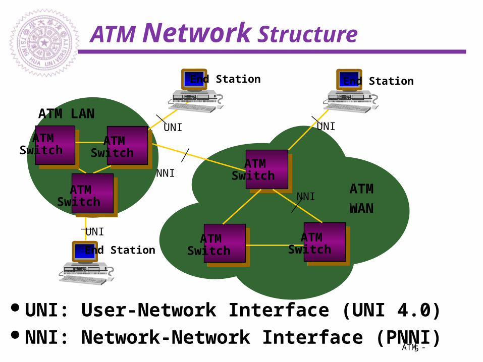
ATM Network Structure
ATM LAN
ATM
WAN
UNI
UNI
NNI
NNI
UNI: User-Network Interface (UNI 4.0)NNI: Network-Network Interface (PNNI)
UNI
End Station
ATM Switch
ATM Switch
ATM Switch
ATM Switch
ATM Switch
ATM Switch
End Station
End Station
6ATM -
. . .
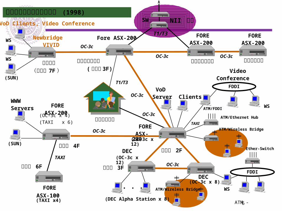
Fore ASX-200 Newbridge VIVID
DEC
DEC
OC-3c
(OC-3c x 4)(TAXI x 6)
(OC-3c x 12)
(OC-3c x 8)
電通中心(綜二館 7F )
清大計算機中心 ( 綜二館 3F)
資訊系 2F
資訊系 3F
電機系 4F
WSWWWServers ATM/FDDI
(DEC Alpha Station x 8)
清華大學高速網路實驗平台 (1998)
遠距教學教室
OC-3c
OC-3c
FDDI
FDDI
FOREASX-200
交大計算機中心
SW
T1/T3
OC-3c
T1/T3
NII 網路
OC-3c
(SUN)
(SUN)
WS
WS
電機系 6F
TAXI
(TAXI x4)
VoD Server Clients
VoD Clients, Video Conference
Video Conference
(OC-3c x 12)
FORE ASX-200
FOREASX-200
FOREASX-100
FOREASX-200
高速電腦中心OC-3c
OC-3c
WS
ATM/Ethernet Hub
Ether-Switch
TAXI
ATM/Wireless Bridge
ATM/Wireless Bridge
7ATM -
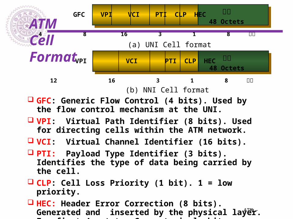
ATMCellFormat
酬載48 Octets
GFC VPI VCI PTI CLP HEC
4 8 16 3 1 8 位元
酬載48 Octets
VPI VCI PTI CLP HEC
12 16 3 1 8 位元
(a) UNI Cell format
(b) NNI Cell format GFC: Generic Flow Control (4 bits). Used by the
flow control mechanism at the UNI. VPI: Virtual Path Identifier (8 bits). Used for
directing cells within the ATM network. VCI: Virtual Channel Identifier (16 bits). PTI: Payload Type Identifier (3 bits). Identifies
the type of data being carried by the cell. CLP: Cell Loss Priority (1 bit). 1 = low priority. HEC: Header Error Correction (8 bits). Generated
and inserted by the physical layer. For first 4 octets. Correct single-bit errors and detect some Multiple-bit errors.
8ATM -
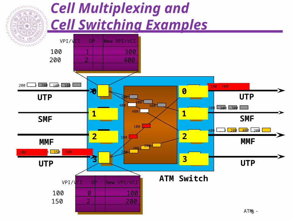
Cell Multiplexing and Cell Switching Examples
100 200 100 100200
150 150 150 100100
200 200 400 200400
300 300 300
100 100
VPI/VCI OP New VPI/VCI
100 0 100150 2 200
0
1
2
3
0
1
2
3
VPI/VCI OP New VPI/VCI
100 1 300200 2 400
ATM Switch
100
100
200200
200
300300
300
400
400
UTP
UTP
SMF
MMF
UTP
UTP
SMF
MMF
9ATM -
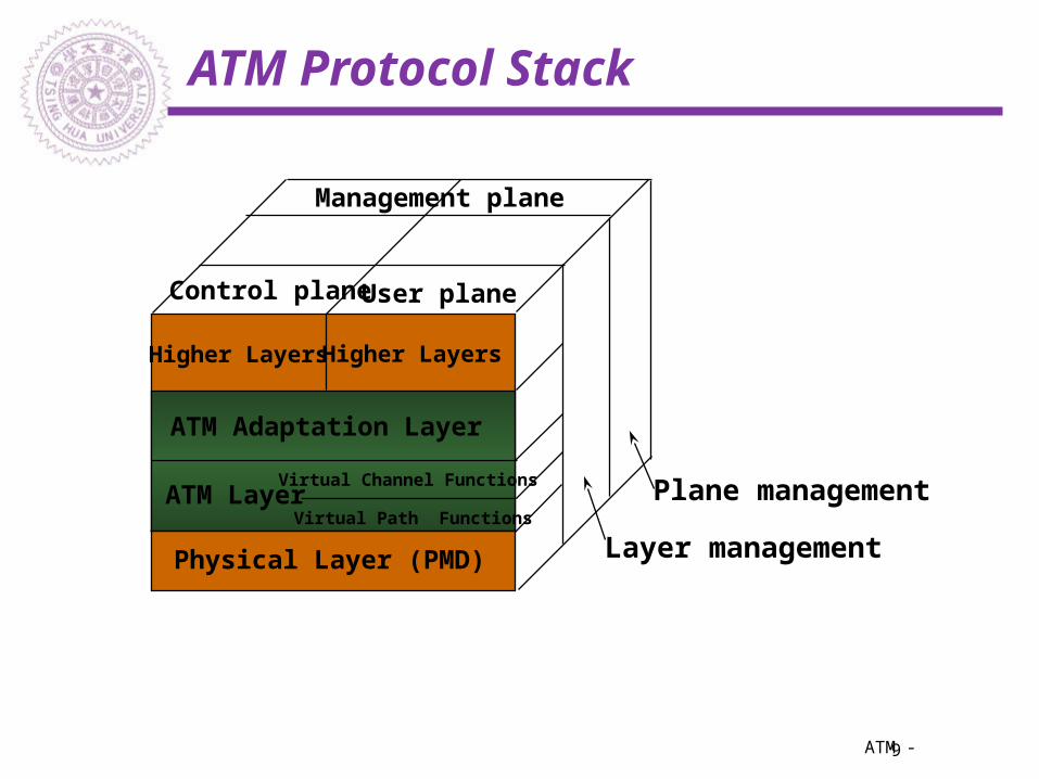
ATM Protocol Stack
Physical Layer (PMD)
ATM Layer
ATM Adaptation Layer
Higher LayersHigher Layers
Control planeUser plane
Management plane
Layer management
Plane managementVirtual Channel Functions
Virtual Path Functions

10ATM -
ATM Layer Service
Transparent transfer of 48-octet data unitDeliver data in sequence on a connectionTwo levels of multiplexingThree types of connections
Point-to-point Point-to-Multipoint Multipoint-to-Multipoint
Transport is best-effortNetwork QoS negotiationTraffic control and congestion control
11ATM -
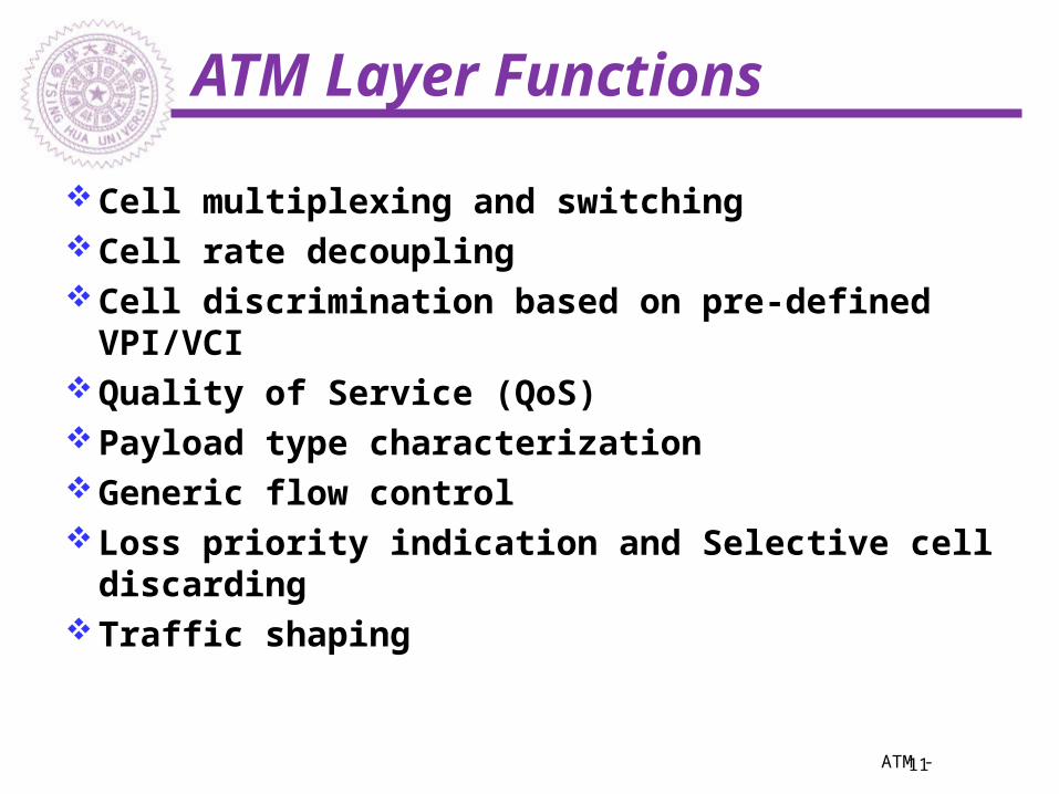
ATM Layer Functions
Cell multiplexing and switchingCell rate decouplingCell discrimination based on pre-defined
VPI/VCIQuality of Service (QoS)Payload type characterizationGeneric flow controlLoss priority indication and Selective cell
discardingTraffic shaping
12ATM -
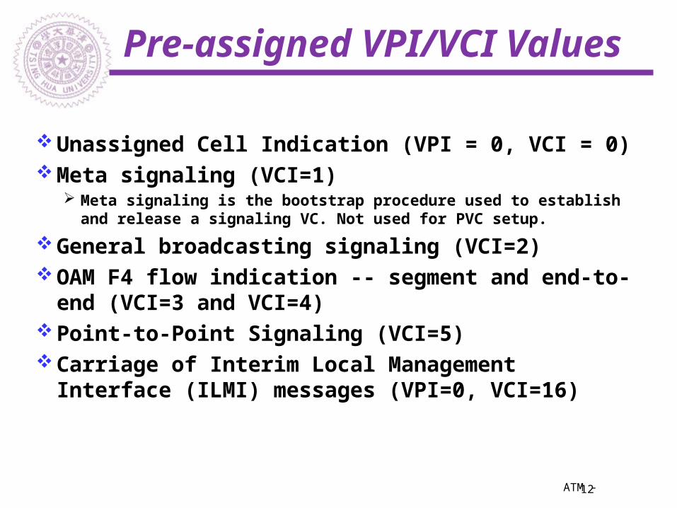
Pre-assigned VPI/VCI Values
Unassigned Cell Indication (VPI = 0, VCI = 0)Meta signaling (VCI=1)
Meta signaling is the bootstrap procedure used to establish and release a signaling VC. Not used for PVC setup.
General broadcasting signaling (VCI=2)OAM F4 flow indication -- segment and end-
to-end (VCI=3 and VCI=4)Point-to-Point Signaling (VCI=5)Carriage of Interim Local Management
Interface (ILMI) messages (VPI=0, VCI=16)
13ATM -
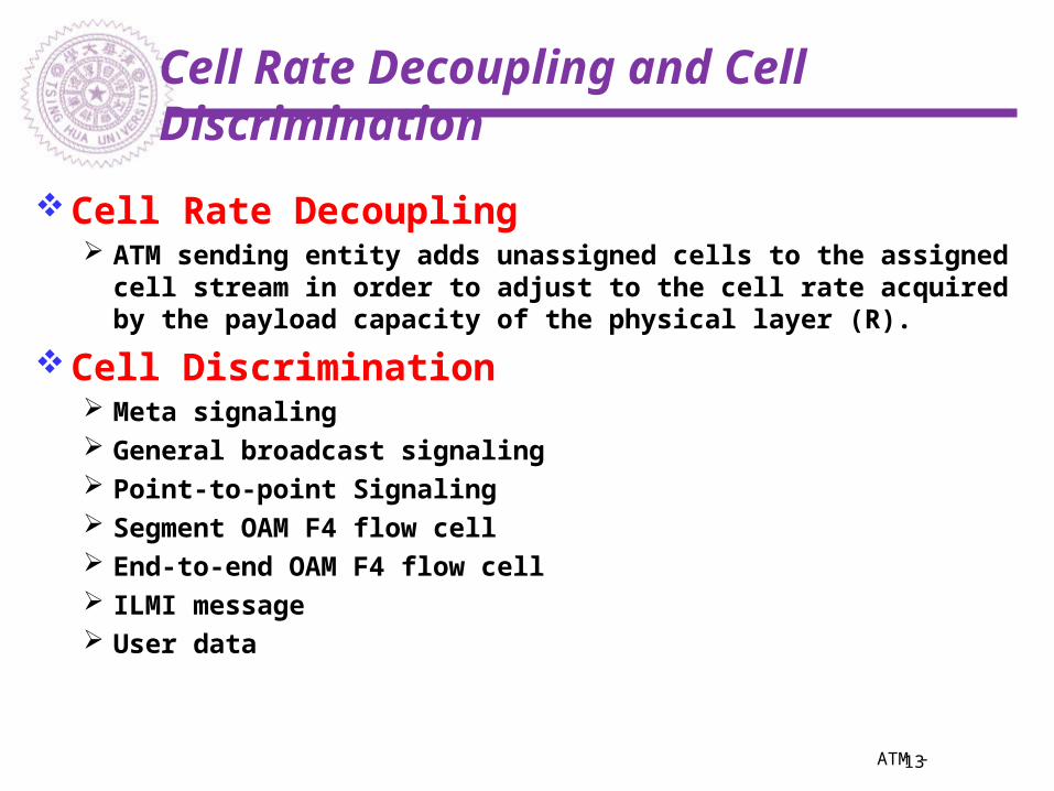
Cell Rate Decoupling and Cell Discrimination
Cell Rate Decoupling ATM sending entity adds unassigned cells to the assigned cell stream
in order to adjust to the cell rate acquired by the payload capacity of the physical layer (R).
Cell Discrimination Meta signaling General broadcast signaling Point-to-point Signaling Segment OAM F4 flow cell End-to-end OAM F4 flow cell ILMI message User data

14ATM -
Virtual Channels, Virtual Paths, and the Physical Channel
Virtual PathVirtual ChannelPhysical link
100 100
200 200
300 300
100200
100200300
10203040
Connection (VPI/VCI) =
(100,100),(100,200),(200,100),
(200,200),(200,300),(300,10),
(300,20),(300,30),(300,40)
100/100200/300300/10300/40
100200
100200300
10203040
Virtual PathVirtual Channel
Cell

15ATM -
Virtual Channels
The virtual channel (VC) is the fundamental unit of transport in a B-ISDN. Each ATM cell contains an explicit label in its header to identify the virtual channel.
a Virtual Channel Identifier (VCI)a Virtual Path Identifier (VPI)
A virtual channel (VC) is a communication channel that provides for the transport of ATM cells between two or more endpoints for information transfer.
A Virtual Channel Identifier (VCI) identifiers a particular VC within a particular VP over a UNI or NNI.
A specific value of VCI has no end-to-end meaning.

16ATM -
Virtual Paths
A Virtual Path (VP) is a group of Virtual Channels that are carried on the same physical facility and share the same Virtual Path Identifier (VPI) value.
The VP boundaries are delimited by Virtual Path Terminators (VPT).
AT VPTs, both VPI and VCI are processed. Between VPTs associated with the same VP,
only the VPI values are processed (and translated) at ATM network elements.
The VCI values are processed only at VPTs, and are not translated at intermediate ATM network elements.

17ATM -
Why Virtual Paths and Virtual Channel ?
A B
(1)
VCI OP
(1) 2 (2)
NewVCI
(127) 2 (35)
0 1
255
0 1
255
(2)(3)
(127)(35)
(255)
(208)(254)
(38)
(208) 2 (254)
0
1
255
Assume the identification field contains 8 bits. All used
as VCI. Then the size of the mapping table is 256.VCI OP
(2) 1 (3)
NewVCI
(35) 1 (255) (254) 1 (38)
01
255
18ATM -
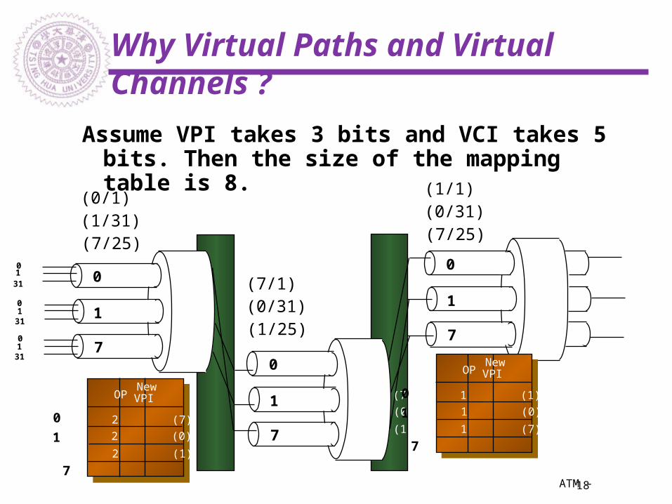
Why Virtual Paths and Virtual Channels ?
0
1
7
0
1
7
0
1
7
(0/1)
(7/1)
(1/1)
(1/31)
(0/31)
(0/31)
(7/25)
(1/25)
(7/25)
0 1
31
0 1
31
0 1
31
7
VPI OP
(0) 2 (7)
NewVPI
(1) 2 (0)
0
1 (7) 2 (1)
VPI OP
(7) 1 (1)
NewVPI
(0) 1 (0)
0
1 (1) 1 (7)
7
Assume VPI takes 3 bits and VCI takes 5 bits. Then the size of the mapping table is 8.

19ATM -
Virtual Channels Examples
1A D
1C B
(300,10)
(100,20)(300,20)
(100,10)
(300,10)
(200,20) (200,10)
(100,10)
(100,20)
23
1 2
24
2
VPI/VCI OP
(100,10) 2 (200,10)
NewVPI/VCI
(100,20) 2 (200,20)
VPI/VCI OP
(200,10) 3 (300,20)
NewVPI/VCI
(200,20) 2 (300,10)
VPI/VCI OP
(300,20) 2 (100,20)
NewVPI/VCI
VPI/VCI OP
(200,10) 4 (300,10)
NewVPI/VCI
a
b
c
d
Port (a,1)
Port (c,2)
Port (d,1) Port (b,1)
VPI/VCI OP
(100,10) 4 (200,10)
NewVPI/VCI
Port (b,2)
4
1 (100,20)
VPI/VCI
1 (300,10)
VPI/VCI
1 (300,10)
VPI/VCI
1 (100,10)
VPI/VCI
連線 1 (100,10)
VPI/VCI
輸出連線
2 (100,20)
(200,10)
輸出連線
輸入連線
輸入連線
輸入連線 連線
連線
連線
連線
20ATM -
ATM Adaptation Layers (AAL)
AAL Reference StructureAAL Type 1AAL Type 2AAL Type 3/4AAL Type 5SAAL (Signaling AAL)
21ATM -
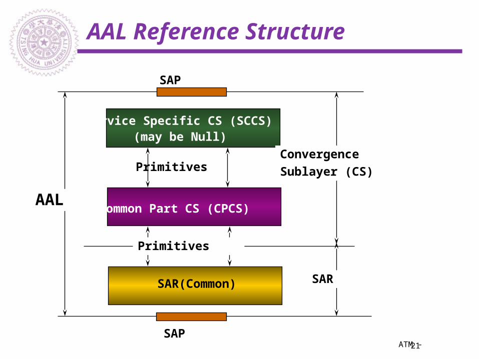
AAL Reference Structure
Service Specific CS (SCCS)(may be Null)
Common Part CS (CPCS)
SAR(Common)
AAL
ConvergenceSublayer (CS)
SAR
SAP
SAP
Primitives
Primitives

22ATM -
AAL
AAL
Service Specific Layers
ATM
Transmission Convergence
Sublayer
PMD
Layer
MGMT
...
...
48 byte payloads
add 5 byte header
message

23ATM -
AAL Functions
Functions ParametersError Detection CRC, length, correlation tagsFraming of user data units Payload type/segment typeCell sequence indication Cell sequence count fieldMultiplexing Message ID (MID)Error Correction FEC, retransmissionFlow Control Credit windowTiming Recovery Time stamp

24ATM -
ATM Adaptation Layers (AAL)
In order to carry data units longer than 48 octets in ATM cells, an adaptation layer is needed.
The ATM adaptation layer (AAL) provides for segmentation and reassembly of higher-layer data units and for detection of errors in transmission.
Since the ATM layer simply carries cells without concern for their contents, a number of different AALs can be used across a single ATM interface.
The AAL maps the user, control, or management protocol data units into the information field of the ATM cell and vice versa.
To reflect the spectrum of applications, four service classes have been defined by CCITT.
25ATM -
CCITT Services Classifications
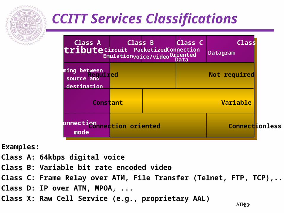
Timing between source and destination
Class A Class B Class C Class D
Required Not required
Bit Rate Constant Variable
Connection
modeConnection oriented Connectionless
CircuitEmulation
Packetizedvoice/video
ConnectionOriented
DataDatagramAttribute
Examples: Class A: 64kbps digital voice Class B: Variable bit rate encoded video Class C: Frame Relay over ATM, File Transfer (Telnet, FTP, TCP),... Class D: IP over ATM, MPOA, ... Class X: Raw Cell Service (e.g., proprietary AAL)
26ATM -
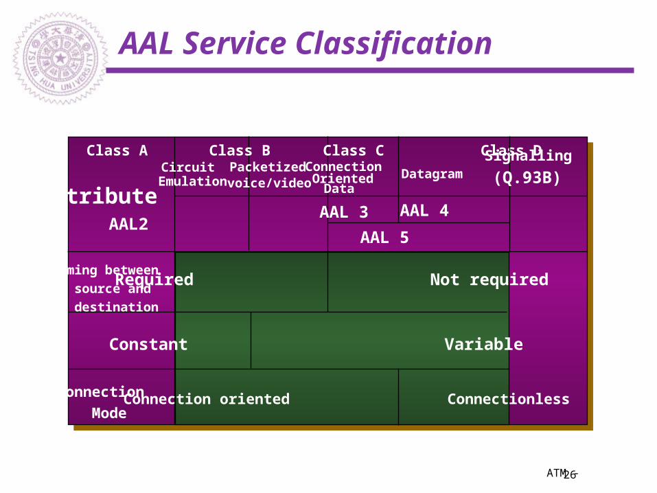
AAL Service Classification
Timing between source and destination
Class A Class B Class C Class D
Required Not required
Bit Rate Constant Variable
Connection
ModeConnection oriented Connectionless
CircuitEmulation
Packetizedvoice/video
ConnectionOriented
DataDatagram
AttributeAAL1 AAL2 SAAL
AAL 5
AAL 4AAL 3
Signalling
(Q.93B)
27ATM -
AAL Types
Five AALs have been accepted for consideration by the CCITT.
AAL 1 is meant for constant-bit-rate services (voice). AAL 2 is meant for variable-bit-rate services with a
required timing relationship between source and destination (audio and video).
AAL 3 was originally meant for connection-oriented variable -bit-rate services without a required timing relationship; it has now been merged with AAL 4.
AAL 3/4 and 5 are meant for connectionless services (e.g. connectionless data).
Only AALs 3/4 and 5 are of interest for IP networking.
28ATM -
AAL 1 (Constant Bit Rate -CBR) Functions
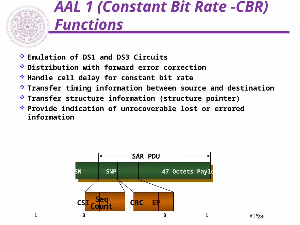
Emulation of DS1 and DS3 Circuits Distribution with forward error correction Handle cell delay for constant bit rate Transfer timing information between source and destination Transfer structure information (structure pointer) Provide indication of unrecoverable lost or errored information
Header SN SNP 47 Octets Payload
SAR PDU
CSI SeqCount EPCRC
1 3 3 1
29ATM -
AAL 2 Protocol Data Unit (PDU)
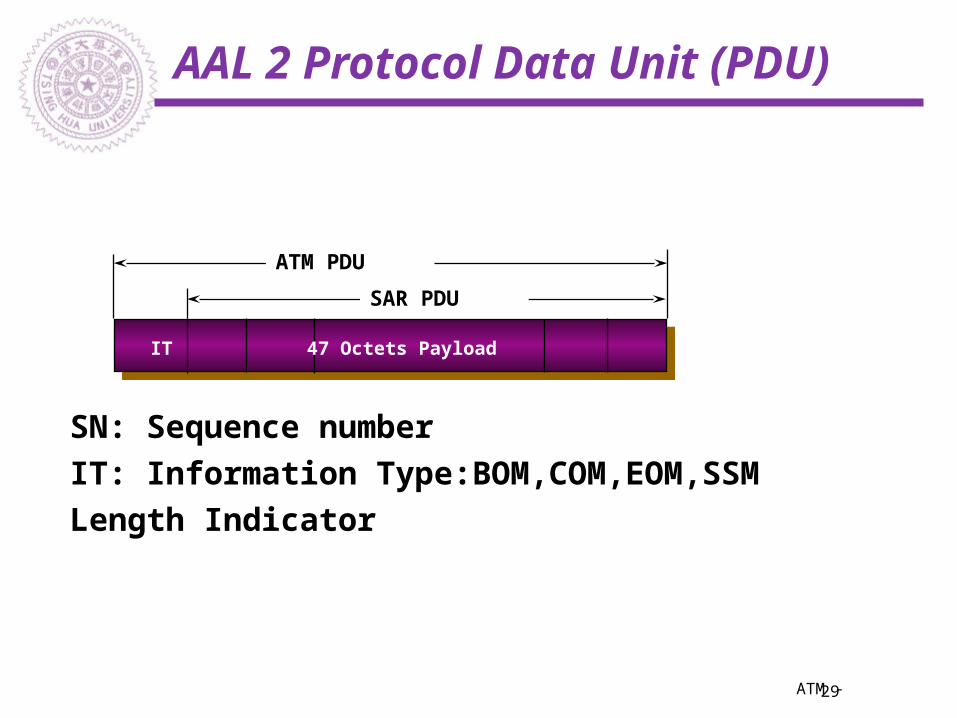
Header SN IT 47 Octets Payload LI CRC
SAR PDU
ATM PDU
SN: Sequence number
IT: Information Type:BOM,COM,EOM,SSM
Length Indicator

30ATM -
AAL 3/4
The variable bit rate (VBR) adaptation layer, defined in CCITT recommendation I.363, is defined for services (e.g. data) that require bursty bandwidth.
Comprises two sublayers:the convergence sublayer (CS) the segmentation and reassembly
sublayer (SAR)
31ATM -
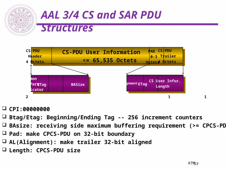
AAL 3/4 CS and SAR PDU Structures
CS-PDU
Header
4 Octets
CS-PDU User Information <= 65,535 Octets
CS-PDU
Trailer
4 Octets
PAD
0-3
Octets
Common
Part
IndicatorBTag BASize Alignment
CS User Infor.
LengthETag
1 1 2 1 1 2
CPI:00000000 Btag/Etag: Beginning/Ending Tag -- 256 increment counters BAsize: receiving side maximum buffering requirement (>= CPCS-PDU) Pad: make CPCS-PDU on 32-bit boundary AL(Alignment): make trailer 32-bit aligned Length: CPCS-PDU size

32ATM -
AAL 3/4 SAR Sublayer
SAR-PDU
Header
2 Octets
Segmentation Unit ,SAR-PDU Payload 44 Octets
SAR-PDU
Trailer
2 Octets
SAR Type
Length SAR SN
MID SAR-PDU CRC
2 4 1 9 6 10
p
ST: COM(00),BOM(10),EOM(01),SSM(11) SN: Modulo 16 sequence counter P(Priority): 1- Priority CS-PDU, 0- Normal CS-PDU MID (Multiplexing ID) -- Multiplexing multiple CPCS connections on a single ATM connection LI: Length <=44 CRC on Cell Header, SAR-PDU payload and LI

33ATM -
AAL 5 PDU Structure
The Simple and Efficient Adaptation Layer (SEAL), attempts to reduce the complexity and overhead of AAL 3/4.
It eliminates most of the overhead of AAL 3/4.
AAL 5 comprises a convergence sublayer and a SAR sublayer, although the SAR is essentially null.CS-PDU User Information
<= 65,535 Octets
CS-PDU
Trailer
8 Octets
PAD
0-47
Octets
Protocol
Control CRCLength
2 2 4
34ATM -
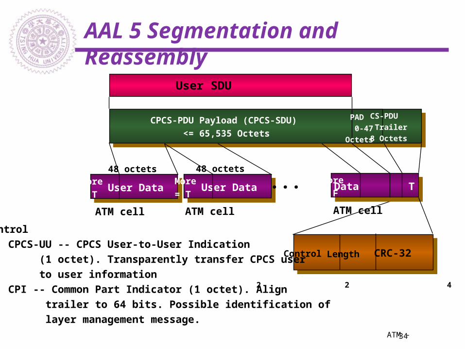
AAL 5 Segmentation and Reassembly
CPCS-PDU Payload (CPCS-SDU) <= 65,535 Octets
CS-PDU
Trailer
8 Octets
PAD
0-47
Octets
Control CRC-32Length
2 2 4
User SDU
User DataMore= T
User DataMore= T
Data TMore= F
...
Control
CPCS-UU -- CPCS User-to-User Indication
(1 octet). Transparently transfer CPCS user
to user information
CPI -- Common Part Indicator (1 octet). Align
trailer to 64 bits. Possible identification of
layer management message.
48 octets 48 octets
ATM cell ATM cell ATM cell

35ATM -
AAL 5
A datagram is converted to a CS-PDU by adding the pad (if necessary) and trailer.
The CS-PDU is breaked into 48-octet SAR-PDUs and transmitted in an ATM cell.
Since there is no AAL 5 SAR header, an end-of-frame indication in the ATM cell header is required: SDU type of 1 (binary value 0X1) in the PTI field.
The receiver simply concatenates the received cells, watching for the end-of-frame indication.
The higher layer is responsible for ignoring or using the PDUs with CRC errors.
36ATM -
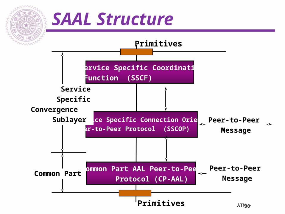
SAAL Structure
Service Specific Coordination Function (SSCF)
Service Specific Connection Oriented Peer-to-Peer Protocol (SSCOP)
Common Part AAL Peer-to-Peer Protocol (CP-AAL)
Service SpecificConvergence Sublayer
Common Part
Peer-to-Peer Message
Peer-to-Peer Message
Primitives
Primitives
37ATM -
SAAL
Reside between Q.93B and ATM Layer.
SAAL is used to provide reliable transport of Q.93B messages between peer Q.93B entities.
SAAL CP-AAL uses AAL5 Common Part Protocol.
SSCOP can be used for any reliable service.
38ATM -
Interconnection with Legacy LANs
LAN EmulationIP-Over-ATMMultiple Protocol Over ATM
(MPOA)IP Switching

39ATM -
Summary of ATM Networks
Switching-Based Network Architecture
Connection-Oriented ProtocolQoS Guaranteed ServicesAggregated BandwidthMultiple Data Rates and
Interfaces