Embed Size (px)
Citation preview
CS3162 Introduction to Computer GraphicsHelena Wong, 2001
Slides - Chapter 1 to 3 1
1. Application of Computer Graphics
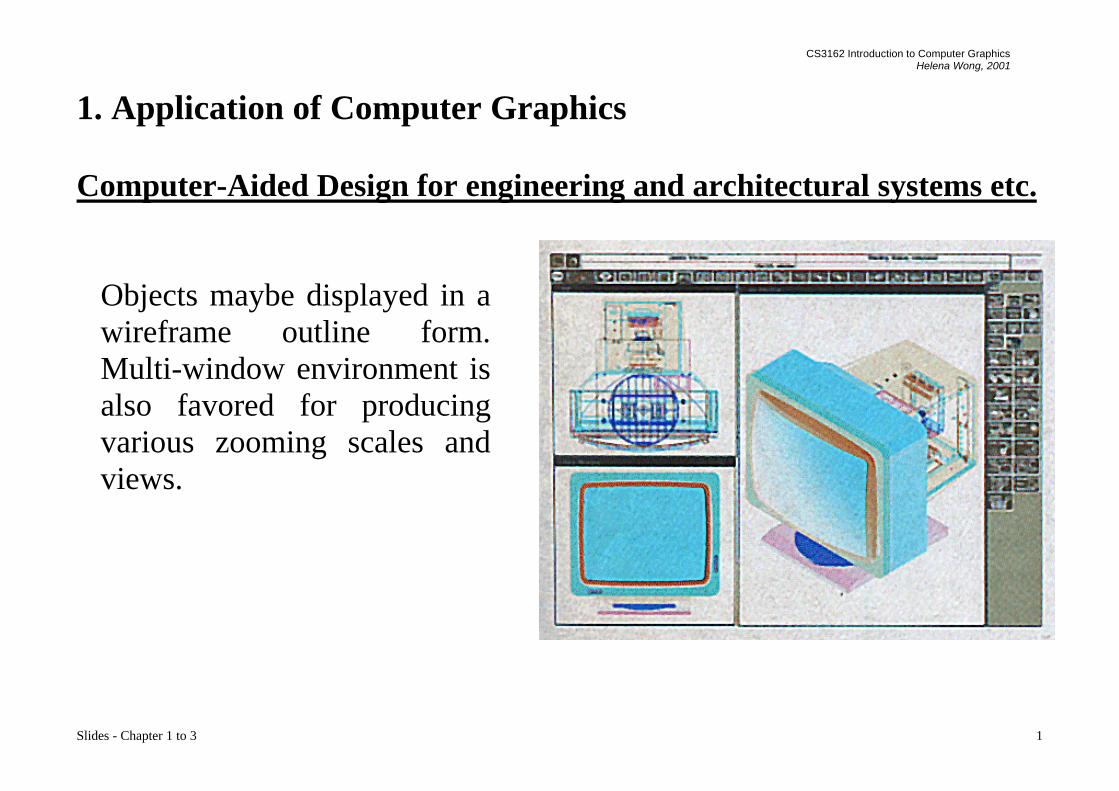
Computer-Aided Design for engineering and architectural systems etc.
Objects maybe displayed in awireframe outline form.Multi-window environment isalso favored for producingvarious zooming scales andviews.

CS3162 Introduction to Computer GraphicsHelena Wong, 2001
Slides - Chapter 1 to 3 2
Animations are useful for testing performance.
Simulation of vehicle performance during lane changes.

CS3162 Introduction to Computer GraphicsHelena Wong, 2001
Slides - Chapter 1 to 3 3
Presentation Graphics
To produce illustrationswhich summarize variouskinds of data. Except 2D,3D graphics are goodtools for reporting morecomplex data.
2D Bar Chart and Pie Chart linked to aGeographical Chart

CS3162 Introduction to Computer GraphicsHelena Wong, 2001
Slides - Chapter 1 to 3 4
3D Bar Chart, Exploded Pie Chart, Line Graph

CS3162 Introduction to Computer GraphicsHelena Wong, 2001
Slides - Chapter 1 to 3 5
Surface Chart Plotting 2D contours in the groundplane, height field is plotted as a
surface

CS3162 Introduction to Computer GraphicsHelena Wong, 2001
Slides - Chapter 1 to 3 6
Computer Art
Painting packages are available. With cordless, pressure-sensitive stylus,artists can produce electronic paintings which simulate different brushstrokes, brush widths, and colors.
Photorealistic techniques, morphing and animations are very useful incommercial art. For films, 24 frames per second are required. For videomonitor, 30 frames per second are required.
Cartoon drawing.

CS3162 Introduction to Computer GraphicsHelena Wong, 2001
Slides - Chapter 1 to 3 7
A Van Gogh look-alikecreated with a cordless,
pressure-sensitive stylus. This picture combines renderings ofleaves, flower petals, and electronics
components with scanned images.

CS3162 Introduction to Computer GraphicsHelena Wong, 2001
Slides - Chapter 1 to 3 8
EntertainmentMotion pictures, Music videos, and TV shows, Computer games
Education and TrainingTraining with computer-generated models of specialized systems such asthe training of ship captains and aircraft pilots.
A large, enclosed flight simulatorwith a full-color visual system and6 degrees of freedom in its motion.

CS3162 Introduction to Computer GraphicsHelena Wong, 2001
Slides - Chapter 1 to 3 9

CS3162 Introduction to Computer GraphicsHelena Wong, 2001
Slides - Chapter 1 to 3 10
VisualizationFor analyzing scientific, engineering, medical and business data orbehavior. Converting data to visual form can help to understand massvolume of data very efficiently.
A method of graphing and modeling data distributedover a sperical surface.

CS3162 Introduction to Computer GraphicsHelena Wong, 2001
Slides - Chapter 1 to 3 11
Visualizing cardiac activation levels of a dog heart.

CS3162 Introduction to Computer GraphicsHelena Wong, 2001
Slides - Chapter 1 to 3 12
Numerical model of the surface of a thunderstorm
CS3162 Introduction to Computer GraphicsHelena Wong, 2001
Slides - Chapter 1 to 3 13
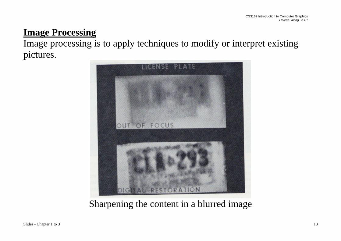
Image ProcessingImage processing is to apply techniques to modify or interpret existingpictures.
Sharpening the content in a blurred image

CS3162 Introduction to Computer GraphicsHelena Wong, 2001
Slides - Chapter 1 to 3 14
Examples of Morphing
CS3162 Introduction to Computer GraphicsHelena Wong, 2001
Slides - Chapter 1 to 3 15
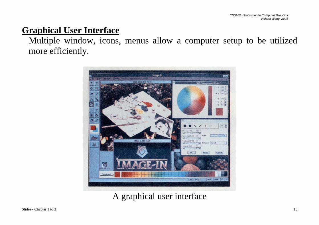
Graphical User InterfaceMultiple window, icons, menus allow a computer setup to be utilizedmore efficiently.
A graphical user interface

CS3162 Introduction to Computer GraphicsHelena Wong, 2001
Slides - Chapter 1 to 3 16
2. Overview of Graphics Systems
2.1 Cathode-Ray Tubes (CRT) - still the most common video displaydevice presently
Electrostatic deflection of the electron beam in a CRT

CS3162 Introduction to Computer GraphicsHelena Wong, 2001
Slides - Chapter 1 to 3 17
An electron gun emits a beam of electrons, which passes through focusingand deflection systems and hits on the phosphor-coated screen. Thenumber of points displayed on a CRT is referred to as the resolution (eg.1024x768). Different phosphors emit small light spots of different colors,which can combine to form a range of colors. A common methodology forcolor CRT display is the Shadow-mask method.
The light emitted by phosphor fades very rapidly, so it needs to redraw thepicture repeatedly. There are 2 kinds of redrawing mechanisms: Raster-Scan and Random-Scan

CS3162 Introduction to Computer GraphicsHelena Wong, 2001
Slides - Chapter 1 to 3 18
Illustration of a shadow-mask CRT

CS3162 Introduction to Computer GraphicsHelena Wong, 2001
Slides - Chapter 1 to 3 19
Raster-Scan
The electron beam is swept across the screen one row at a time from top tobottom. As it moves across each row, the beam intensity is turned on andoff to create a pattern of illuminated spots. This scanning process is calledrefreshing. Each complete scanning of a screen is normally called a frame.

CS3162 Introduction to Computer GraphicsHelena Wong, 2001
Slides - Chapter 1 to 3 20
The refreshing rate, called the frame rate, is normally 60 to 80 frames persecond, or described as 60 Hz to 80 Hz.
Picture definition is stored in a memory area called the frame buffer. Thisframe buffer stores the intensity values for all the screen points. Eachscreen point is called a pixel (picture element).
On black and white systems, the frame buffer storing the values of thepixels is called a bitmap. Each entry in the bitmap is a 1-bit data whichdetermine the on (1) and off (0) of the intensity of the pixel.
On color systems, the frame buffer storing the values of the pixels is calleda pixmap (Though nowadays many graphics libraries name it as bitmaptoo). Each entry in the pixmap occupies a number of bits to represent thecolor of the pixel. For a true color display, the number of bits for eachentry is 24 (8 bits per red/green/blue channel, each channel 28=256 levelsof intensity value, ie. 256 voltage settings for each of the red/green/blueelectron guns).

CS3162 Introduction to Computer GraphicsHelena Wong, 2001
Slides - Chapter 1 to 3 21
Random-Scan (Vector Display)
The CRT's electron beam is directed only to the parts of the screen where apicture is to be drawn. The picture definition is stored as a set of line-drawing commands in a refresh display file or a refresh buffer in memory.
Random-scan generally have higher resolution than raster systems and canproduce smooth line drawings, however it cannot display realistic shadedscenes.

CS3162 Introduction to Computer GraphicsHelena Wong, 2001
Slides - Chapter 1 to 3 22
2.2 Flat-Panel Displays - will be the most common video display devicevery soon.
Reduced thickness, volumn, weight, and power requirements compared toCRT.
Liquid-Crystal Displays (LCDs)
- Liquid crystal refers to compounds which are in crystalline arrangement,but can flow like liquid.

CS3162 Introduction to Computer GraphicsHelena Wong, 2001
Slides - Chapter 1 to 3 23
- The light source passes through a liquid-crystal material that can bealigned to either block or transmit the light.
- 2 glass plates, each containing a light polarizer at right angles to theother, sandwich a liquid crystal material.
- Rows of horizontal transparent conductors are built into one glass page.Columns of vertical conductors are put into the other plate. Theintersection of 2 conductors defines a pixel position. -- Passive-matrixLCD
- In the "on" state, polarized light passing through the material is twistedso that it will pass through the opposite polarizer.
- Different materials can display different colors.
- By placing thin-film transistors at pixel locations, voltage at each pixelcan be controlled. -- Active-matrix LCD.

CS3162 Introduction to Computer GraphicsHelena Wong, 2001
Slides - Chapter 1 to 3 24
2.3. Graphics Systems
Block diagram of a CRT graphics system
In this context we discuss the graphics systems of raster-scan devices. Agraphics processor accepts graphics commands from the CPU and executesthe graphics commands which may involve drawing into the frame buffer.The frame buffer acts as a temporary store of the image and also as adecoupler to allow the graphics processor and the display controller tooperate at different speeds. The display controller reads the frame bufferline by line and generates the control signals for the screen.

CS3162 Introduction to Computer GraphicsHelena Wong, 2001
Slides - Chapter 1 to 3 25
Graphics commands:- Draw point- Draw polygon- Draw text- Clear frame buffer- Change drawing color
2 kinds of graphics processors:
2D graphics processors execute commands in 2D coordinates. Whenobjects overlap, the one being drawn will obscure objects drawn previouslyin the region. BitBlt operations (Bit Block Transfer) are usually providedfor moving/copying one rectangular region of frame buffer contents toanother region.

CS3162 Introduction to Computer GraphicsHelena Wong, 2001
Slides - Chapter 1 to 3 26
3D graphics processors execute commands in 3D coordinates. Whenobjects overlap, it is required to determine the visibility of the objectsaccording to the z values.
Display Controller for a raster display device reads the frame buffer andgenerates the control signals for the screen, ie. the signals for horizontalscanning and vertical scanning. Most display controllers include acolormap (or video look-up table). The major function of a colormap is toprovide a mapping between the input pixel value to the output color.

CS3162 Introduction to Computer GraphicsHelena Wong, 2001
Slides - Chapter 1 to 3 27
2.4. Input Devices
Common devices: keyboard, mouse, trackball and joystickSpecialized devices:Data gloves are electronic gloves for detecting fingers' movement. Insome applications, a sensor is also attached to the glove to detect the handmovement as a whole in 3D space.A tablet contains a stylus and a drawing surface and it is mainly used forthe input of drawings. A tablet is usually more accurate than a mouse, andis commonly used for large drawings.Scanners are used to convert drawings or pictures in hardcopy format intodigital signal for computer processing.Touch panels allow displayed objects or screen positions to be selectedwith the touch of a finger. In these devices a touch-sensing mechanism isfitted over the video monitor screen. Touch input can be recorded usingoptical, electrical, or acoustical methods.

CS3162 Introduction to Computer GraphicsHelena Wong, 2001
Slides - Chapter 1 to 3 28
Ergonomically designed keyboardwith removable palm rest. The
slope of each half of the keyboardcan be adjusted separately.
The SummaSketch III desktoptablet with a 16-button hand cursor.

CS3162 Introduction to Computer GraphicsHelena Wong, 2001
Slides - Chapter 1 to 3 29
An artist's workstation

CS3162 Introduction to Computer GraphicsHelena Wong, 2001
Slides - Chapter 1 to 3 30

CS3162 Introduction to Computer GraphicsHelena Wong, 2001
Slides - Chapter 1 to 3 31
A large floor-model scanner used to scan architectural andengineering drawings up to 40 inches wide.

CS3162 Introduction to Computer GraphicsHelena Wong, 2001
Slides - Chapter 1 to 3 32
2.5 Hard-Copy Devices
Pictures are directed to a printer or plotter to produce hard-copy output on35-mm slides, overhead transparencies, or plain paper. The qualities of thepictures depend on dot size and number of dots per inch (DPI).
Types of printers: line printers, laserjet, ink-jet, dot-matrix
Laserjet printers use a laser beam to create a charge distribution on arotating drum coated with a photoelectric material. Toner is applied to thedrum and then transferred to the paper. To produce color outputs, the 3color pigments (cyan, magenta, and yellow) are deposited on separatepasses.

CS3162 Introduction to Computer GraphicsHelena Wong, 2001
Slides - Chapter 1 to 3 33
Inkjet printers produce output by squirting ink in horizontal rows across aroll of paper wrapped on a drum. To produce color outputs, the 3 colorpigments are shot simultaneously on a single pass along each print line onthe paper.
Inkjet or pen plotters are used to generate drafting layouts and otherdrawings of normally larger sizes. A pen plotter has one or more pens ofdifferent colors and widths mounted on a carriage which spans a sheet ofpaper.

CS3162 Introduction to Computer GraphicsHelena Wong, 2001
Slides - Chapter 1 to 3 34
A large rollfeed penplotter with automaticmulticolor 8-penchanger.

CS3162 Introduction to Computer GraphicsHelena Wong, 2001
Slides - Chapter 1 to 3 35
2.6 Coordinate Representations in Graphics
General graphics packages are designed to be used with Cartesiancoordinate representations (x,y,z). Usually several different Cartesianreference frames are used to construct and display a scene:

CS3162 Introduction to Computer GraphicsHelena Wong, 2001
Slides - Chapter 1 to 3 36
Modeling coordinates are used to construct individual object shapes.
World coordinates are computed for specifying the placement ofindividual objects in appropriate positions.
Normalized coordinates are converted from world coordinates, such thatx,y values are ranged from 0 to 1.
Device coordinates are the final locations on the output devices.

CS3162 Introduction to Computer GraphicsHelena Wong, 2001
Slides - Chapter 1 to 3 37
3. Output Primitives
Shapes and colors of objects can be described internally with pixel arraysor sets of basic geometric structures such as straight line segments andpolygon color areas. The functions provided by graphics programmingpackages to deal with these basic geometric structures are called outputprimitives.
For example:Drawing a point: SetPixel(100,200,RGB(255,255,0));Drawing a line: MoveTo(100,100); LineTo(100,200);Drawing some text: SetText(100,200,"Hello");Drawing an ellipse: Ellipse(100,100,200,200);Painting a picture: BitBlt(100,100,50,50,srcImage,0,0,SRCCOPY);

CS3162 Introduction to Computer GraphicsHelena Wong, 2001
Slides - Chapter 1 to 3 38
3.1 Drawing a Thin Line in Raster Devices
This is to compute intermediate discrete coordinates along the line pathbetween 2 specified endpoint positions. The corresponding entries of thesediscrete coordinates in the frame buffer are then marked with the line colorwanted.
The basic concept is:
- A line can be specified in the form: y = mx + c
- Let m be between 0 to 1, then the slope of the line is between 0 and 45degrees.

CS3162 Introduction to Computer GraphicsHelena Wong, 2001
Slides - Chapter 1 to 3 39
- For the x-coordinate of the left end point of the line, compute thecorresponding y value according to the line equation. Thus we get theleft end point as (x1,y1), where y1 may not be an integer.
- Calculate the distance of (x1,y1) from the center of the pixel immediatelyabove it and call it D1
- Calculate the distance of (x1,y1) from the center of the pixel immediatelybelow it and call it D2
- If D1 is smaller than D2, it means that the line is closer to the upper pixelthan the lower pixel, then, we set the upper pixel to on; otherwise we setthe lower pixel to on.
- Then increment x by 1 and repeat the same process until x reaches theright end point of the line.
- This method assumes the width of the line to be zero

CS3162 Introduction to Computer GraphicsHelena Wong, 2001
Slides - Chapter 1 to 3 40

CS3162 Introduction to Computer GraphicsHelena Wong, 2001
Slides - Chapter 1 to 3 41
Bresenham's Line Algorithm
This algorithm is very efficient since it uses only incremental integercalculations. Instead of calculating the non-integral values of D1 and D2for decision of pixel location, it computes a value, p, which is defined as:
p = (D2-D1)* horizontal length of the lineif p>0, it means D1 is smaller than D2, and we can determine the pixellocation accordingly
However, the computation of p is very easy:The initial value of p is 2 * vertical height of the line - horizontal length ofthe line.At succeeding x locations, if p has been smaller than 0, then, we incrementp by 2 * vertical height of the line, otherwise we increment p by 2 *(vertical height of the line - horizontal length of the line)
All the computations are on integers. The incremental method is applied.
CS3162 Introduction to Computer GraphicsHelena Wong, 2001
Slides - Chapter 1 to 3 42
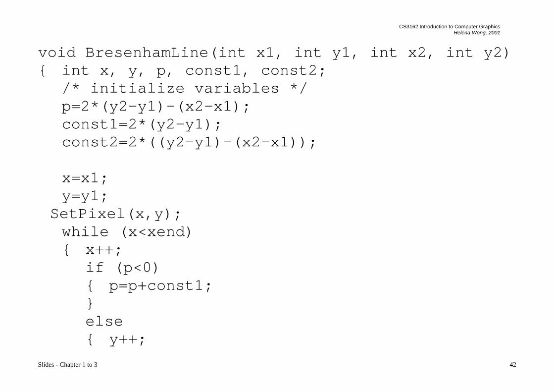
void BresenhamLine(int x1, int y1, int x2, int y2){ int x, y, p, const1, const2;
/* initialize variables */p=2*(y2-y1)-(x2-x1);const1=2*(y2-y1);const2=2*((y2-y1)-(x2-x1));
x=x1;y=y1;
SetPixel(x,y);while (x<xend){ x++;
if (p<0){ p=p+const1;}else{ y++;

CS3162 Introduction to Computer GraphicsHelena Wong, 2001
Slides - Chapter 1 to 3 43
p=p+const2;}SetPixel(x,y);
}}

CS3162 Introduction to Computer GraphicsHelena Wong, 2001
Slides - Chapter 1 to 3 44
3.2 Drawing a Circle in Raster Devices
A circle can be specified in the form: (x-xc)
2 + (y-yc)2 = r2
where (xc,yc) is the center of the circle.
To save time in drawing a circle,we can make use of thesymmetrical property of a circlewhich is to draw the segment of thecircle between 0 and 45 degreesand repeat the segment 8 times asshown in the diagram to produce acircle. This algorithm alsoemploys the incremental methodwhich further improves theefficiency.
CS3162 Introduction to Computer GraphicsHelena Wong, 2001
Slides - Chapter 1 to 3 45
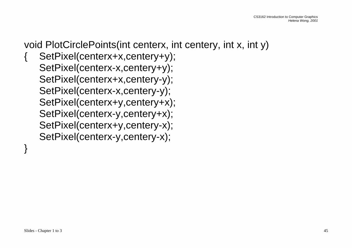
void PlotCirclePoints(int centerx, int centery, int x, int y){ SetPixel(centerx+x,centery+y);
SetPixel(centerx-x,centery+y);SetPixel(centerx+x,centery-y);SetPixel(centerx-x,centery-y);SetPixel(centerx+y,centery+x);SetPixel(centerx-y,centery+x);SetPixel(centerx+y,centery-x);SetPixel(centerx-y,centery-x);
}
CS3162 Introduction to Computer GraphicsHelena Wong, 2001
Slides - Chapter 1 to 3 46
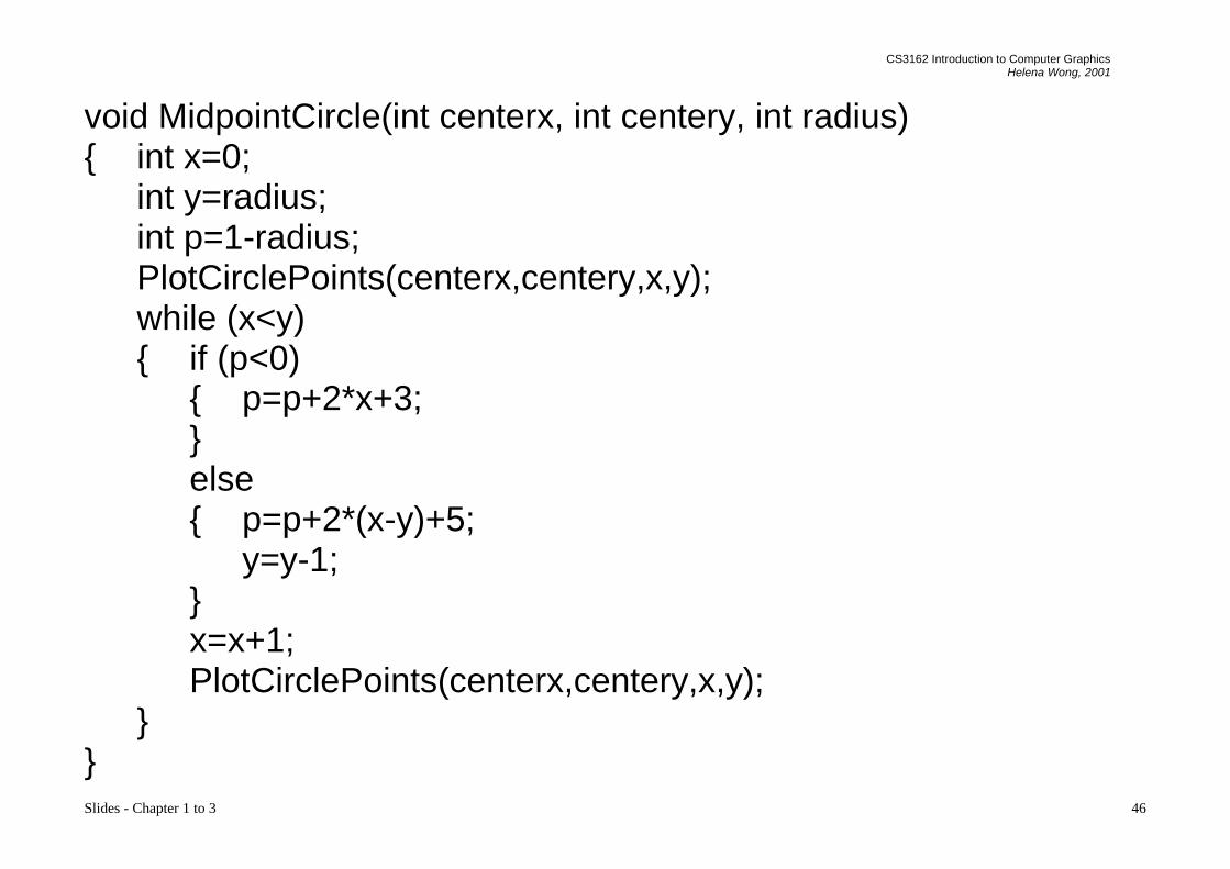
void MidpointCircle(int centerx, int centery, int radius){ int x=0;
int y=radius;int p=1-radius;PlotCirclePoints(centerx,centery,x,y);while (x<y){ if (p<0)
{ p=p+2*x+3;}else{ p=p+2*(x-y)+5;
y=y-1;}x=x+1;PlotCirclePoints(centerx,centery,x,y);
}}

CS3162 Introduction to Computer GraphicsHelena Wong, 2001
Slides - Chapter 1 to 3 47
3.3 Scan-Line Polygon Fill Algorithm
- Basic idea: For each scan line crossing a polygon, this algorithm locatesthe intersection points of the scan line with the polygon edges. Theseintersection points are sorted from left to right. Then, we fill the pixelsbetween each intersection pair.
CS3162 Introduction to Computer GraphicsHelena Wong, 2001
Slides - Chapter 1 to 3 48
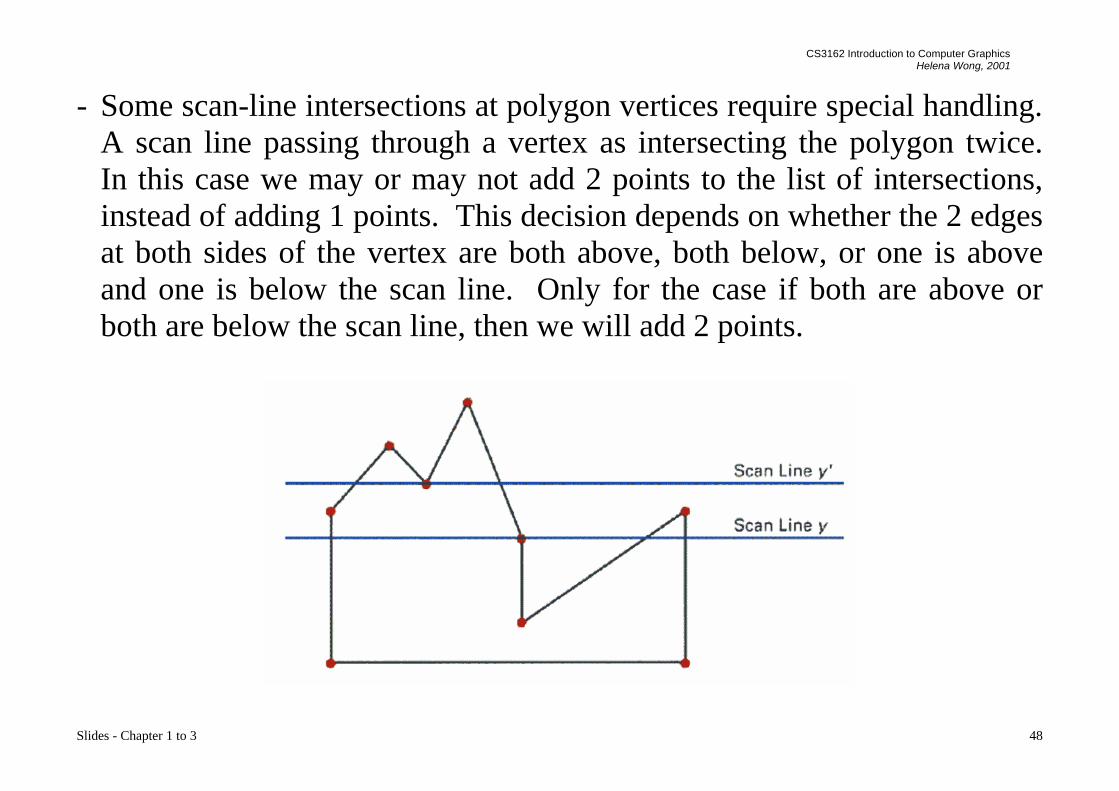
- Some scan-line intersections at polygon vertices require special handling.A scan line passing through a vertex as intersecting the polygon twice.In this case we may or may not add 2 points to the list of intersections,instead of adding 1 points. This decision depends on whether the 2 edgesat both sides of the vertex are both above, both below, or one is aboveand one is below the scan line. Only for the case if both are above orboth are below the scan line, then we will add 2 points.

CS3162 Introduction to Computer GraphicsHelena Wong, 2001
Slides - Chapter 1 to 3 49
- Inside-Outside Tests: The above algorithm only works for standardpolygon shapes. However, for the cases which the edges of the polygonintersect, we need to identify whether a point is an interior or exteriorpoint. Students may find interesting descriptions of 2 methods to solvethis problem in many text books: odd-even rule and nonzero windingnumber rule.

CS3162 Introduction to Computer GraphicsHelena Wong, 2001
Slides - Chapter 1 to 3 50
3.4 Boundary-Fill Algorithm
- This algorithm starts at a point inside a region and paints the interioroutward towards the boundary.
- This is a simple method but not efficient: It is a recursive method whichmay occupy a large stack size in the main memory.
void BoundaryFill(int x, int y, COLOR fill, COLOR boundary){ COLOR current;
current=GetPixel(x,y);if (current<>boundary) and (current<>fill) then{ SetPixel(x,y,fill);
BoundaryFill(x+1,y,fill,boundary);BoundaryFill(x-1,y,fill,boundary);BoundaryFill(x,y+1,fill,boundary);BoundaryFill(x,y-1,fill,boundary);
}}

CS3162 Introduction to Computer GraphicsHelena Wong, 2001
Slides - Chapter 1 to 3 51
- More efficient methods fill horizontal pixel spans across scan lines,instead of proceeding to neighboring points.

CS3162 Introduction to Computer GraphicsHelena Wong, 2001
Slides - Chapter 1 to 3 52
3.5 Flood-Fill Algorithm
- Flood-Fill is similar to Boundary-Fill. The difference is that Flood-Fill isto fill an area which is not defined by a single boundary color.
void FloodFill(int x, int y, COLOR fill, COLORold_color){ if (GetPixel(x,y) == old_color)
{ SetPixel(x,y,fill);FloodFill(x+1,y,fill,old_color);FloodFill(x-1,y,fill,old_color);FloodFill(x,y+1,fill,old_color);FloodFill(x,y-1,fill,old_color);
}}

CS3162 Introduction to Computer GraphicsHelena Wong, 2001
Slides - Chapter 1 to 3 53
3.6 Drawing Text
- A character is defined by its outline which is usually composed of linesand curves.
- We can use a method similar the one for rendering polygon to render acharacter.

CS3162 Introduction to Computer GraphicsHelena Wong, 2001
Slides - Chapter 1 to 3 54
- However, because text is used very oftenly, we usually convert them intobitmaps in advance to improve the drawing efficiency.
- To draw a character on the screen, all we need to do is to copy thecorresponding bitmap to the specified coordinate.
- The problem with this method is that scaling a character with a bitmap toproduce different character sizes would result in a block-like structures(stair-case, aliasing). Hence we normally render a few bitmaps for asingle character to represent different sizes of the same character.

CS3162 Introduction to Computer GraphicsHelena Wong, 2001
Slides - Chapter 1 to 3 55
3.7 Bitmap
- A graphics pattern such as an icon or a character may be neededfrequently, or may need to be re-used.
- Generating the pattern every time when needed may waste a lot ofprocessing time.
- A bitmap can be used to store a pattern and duplicate it to many places onthe image or on the screen with simple copying operations.

CS3162 Introduction to Computer GraphicsHelena Wong, 2001
Slides - Chapter 1 to 3 56
3.8 Properties
- In graphical output primitives, objects are normally associated withproperties. Eg.
Point: colorLine: width, style, colorPolygon: edge color, filling colorText: font size, color, bold or not bold, italic or not, underlined or not,
etc.
In graphical packages, we can specify such properties, eg. In Powerpoint,we can modify the properties of objects by a format command.
In programming tools, we may pass the properties as arguments when wecall the functions of these primitives, or we may pre-select the propertiesbefore calling the functions.